WO2021260874A1 - ガス絶縁変圧器、ガス絶縁変圧システムおよび電圧推定方法 - Google Patents
ガス絶縁変圧器、ガス絶縁変圧システムおよび電圧推定方法 Download PDFInfo
- Publication number
- WO2021260874A1 WO2021260874A1 PCT/JP2020/024974 JP2020024974W WO2021260874A1 WO 2021260874 A1 WO2021260874 A1 WO 2021260874A1 JP 2020024974 W JP2020024974 W JP 2020024974W WO 2021260874 A1 WO2021260874 A1 WO 2021260874A1
- Authority
- WO
- WIPO (PCT)
- Prior art keywords
- voltage
- primary
- shield
- gas
- secondary winding
- Prior art date
- Legal status (The legal status is an assumption and is not a legal conclusion. Google has not performed a legal analysis and makes no representation as to the accuracy of the status listed.)
- Ceased
Links
Images


Classifications
-
- H—ELECTRICITY
- H01—ELECTRIC ELEMENTS
- H01F—MAGNETS; INDUCTANCES; TRANSFORMERS; SELECTION OF MATERIALS FOR THEIR MAGNETIC PROPERTIES
- H01F30/00—Fixed transformers not covered by group H01F19/00
- H01F30/06—Fixed transformers not covered by group H01F19/00 characterised by the structure
- H01F30/10—Single-phase transformers
Definitions
- the present invention relates to a gas-insulated transformer, a gas-insulated transformer system, and a method for estimating the voltage of the primary winding in the gas-insulated transformer and the gas-insulated transformer system.
- a gas-insulated transformer for connecting to a bus or line of a substation or the like to transform and supply a voltage is known.
- An example of such a gas-insulated transformer is disclosed in Patent Document 1.
- Japanese Patent Publication Japanese Patent Laid-Open No. 2004-22557
- One aspect of the present invention enables detection of the primary voltage without unnecessarily complicating or enlarging the configuration of the device or causing an error due to a change in the load connected to the secondary side.
- the purpose is to realize a gas-insulated transformer.
- the gas-insulated transformer includes a core, a secondary winding wound around the core, and the secondary winding outside the outer periphery of the secondary winding.
- the core, the secondary winding wound around the core, and the secondary winding are wound coaxially with the secondary winding outside the outer periphery of the secondary winding.
- the configuration of the device is not unnecessarily complicated or enlarged, or an error due to a change in the load connected to the secondary side is not generated. , It is possible to detect the voltage applied to the primary winding.
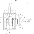
- FIG. It is a figure which shows the structure of the gas insulation transformation system which concerns on Embodiment 1.
- FIG. It is a figure which shows the cross section by XX line in FIG. It is a figure which shows the cross section in the YY line in FIG.
- FIG. It is a block diagram which shows the structure of the main part of the primary voltage estimation apparatus. It is a flowchart which shows the process of estimating a primary voltage by a primary voltage estimation apparatus.
- FIG. 1 is a diagram showing a configuration of a gas-insulated transformer system 100 according to the first embodiment.
- the gas-insulated transformer system 100 includes a transformer 1 (gas-insulated transformer) and a primary voltage estimation device 9. 2 and 3 show a cross section of a main member arranged inside the container 31 of the transformer 1 at a specific cutting position.
- FIG. 2 shows a cross section taken along line XX in FIG.
- FIG. 3 shows a cross section taken along the line YY in FIG.
- Such a gas-insulated transformer system 100 is installed in a power plant or a substation for the purpose of converting high-voltage electric power and supplying it as in-house electric power, for example.
- FIG. 4 is a circuit diagram showing a schematic configuration of the circuit of the transformer 1.
- the transformer 1 is a single-phase grounded transformer.
- the transformer 1 includes a core 10, a primary winding 11, a secondary winding 12, a high voltage shield 13, a low voltage shield 14, a lead connection portion 16, a capacitor 21 (circuit element), a voltage detection terminal 22, a ground terminal 23, and a voltage detection. It includes a vessel 24, a container 31, and a terminal box 32.
- the core 10 is a core material around which the primary winding 11 and the secondary winding 12 are wound.
- the core 10 is formed of a material containing a magnetic material.
- the core 10 is made of iron.
- the secondary winding 12 is wound around the core 10.
- the primary winding 11 is wound coaxially with the secondary winding 12 outside the outer circumference of the secondary winding 12.
- the turns ratio between the primary winding 11 and the secondary winding 12 can be obtained.
- the corresponding secondary voltage is output from the output terminal of the secondary winding 12 (terminals u and v in the circuit diagram of FIG. 4).
- the turns ratio of the primary winding 11 and the secondary winding 12 may be appropriately determined according to the ratio of the desired primary voltage V1 to the secondary voltage.
- the high voltage shield 13 covers the outer circumference of the primary winding 11.
- the high-voltage shield 13 alleviates the influence of the electric field generated by applying the primary voltage V1 supplied from a bus or a line of a substation or the like to the primary winding 11.
- the low voltage shield 14 is provided at a position facing the high voltage shield 13. Specifically, the low voltage shield 14 is arranged between the high voltage shield 13 and a region not covered by the secondary winding 12 of the core 10.
- the low voltage shield 14 is provided at the above position to reduce the influence of members such as the edge of the core 10 and the fixture of the core 10 on the electric field due to the primary winding 11. Further, the axial direction of the secondary winding 12 is longer than the axial direction of the primary winding 11. Therefore, in the transformer 1, the secondary winding 12 also acts as a shield that reduces the influence of members such as the edge of the core 10 and the fixture of the core 10 on the electric field due to the primary winding 11.
- Both the high-voltage shield 13 and the low-voltage shield 14 are formed of conductors. Further, the high voltage shield 13 and the low voltage shield 14 are not connected to each other by a conductor. Since the low voltage shield 14 is provided at a position facing the high voltage shield 13, the capacitance C1 exists between the high voltage shield 13 and the low voltage shield 14 in the transformer 1. In the following description, it is assumed that the high voltage shield 13 and the low voltage shield 14 are connected to each other via the virtual capacitor 15 having the capacitance C1.
- the lead connection portion 16 is a member to which the lead 12a of the secondary winding 12 is connected. As shown in FIG. 1, in the transformer 1, the low voltage shield 14 is arranged between the high voltage shield 13 and the lead connection portion 16. Therefore, the low voltage shield 14 also reduces the influence of the lead connection portion 16 on the electric field due to the primary winding 11.
- the capacitor 21 is a circuit element having one end connected to the low voltage shield 14 and the other end connected to the ground terminal 23.
- the ground terminal 23 is a terminal for grounding the capacitor 21. Therefore, the potential of the low voltage shield 14 is in a state of floating from the ground potential by the amount of the voltage applied to the capacitor 21.
- the voltage detection terminal 22 is a terminal for detecting the voltage Vm applied to the capacitor 21.
- the voltage detection terminal 22 is connected to one end of the capacitor 21 connected to the low voltage shield 14. Therefore, in the transformer 1, the voltage Vm applied to the capacitor 21 can be detected by the voltage detection terminal 22 and the ground terminal 23.
- the voltage detector 24 detects the voltage Vm applied to the capacitor 21.
- the voltage detector 24 is connected between the voltage detection terminal 22 and the ground terminal 23. In other words, the voltage detector 24 is connected between one end of the capacitor 21 connected to the low voltage shield 14 and the ground terminal 23. As a result, the voltage detector 24 can detect the voltage Vm applied to the capacitor 21.
- the voltage detector 24 a known detector can be used. In the first embodiment, since the transformer 1 includes a voltage detector, it is not necessary to separately connect the voltage detector.
- the container 31 houses the core 10, the primary winding 11, the secondary winding 12, the high-voltage shield 13 and the low-voltage shield 14 in a sealed state.
- the container 31 is filled with, for example, 0.55 MPa of SF 6 as an insulating gas.
- the pressure and type of gas filled in the container 31 are not limited to this.
- the terminal 11a on the non-grounded side for inputting the primary voltage V1 to the primary winding 11 is provided at a position drawn out from the container 31 via the bushing 33. Further, instead of the bushing 33, an insulating spacer having a main body formed of an insulating resin and an embedded conductor provided so as to penetrate the main body may be used. The terminal 11a is connected to the primary winding 11 by a connecting conductor 11b.
- the terminal box 32 further accommodates other input / output terminals for the primary winding 11 and the secondary winding 12.
- the input terminal terminal V in the circuit diagram of FIG. 4
- the output terminal (same as the terminal u and the terminal v) connected to the lead 12a of the above is accommodated.
- terminal box 32 does not need to be filled with an insulating gas.
- the container 31 is provided with a pull-out member 34 for pulling out the lead wire connected to the low-voltage shield 14 from the inside of the container 31 into the terminal box 32.
- the capacitor 21 is arranged in the terminal box 32. That is, the capacitor 21 is arranged outside the container 31. Therefore, when a defect occurs in the capacitor 21, the defect can be dealt with without opening the container 31 filled with the insulating gas.
- the value of the capacitance C1 is a known value uniquely determined according to the size and shape of the high pressure shield 13 and the low pressure shield 14, the type and pressure of the gas filled in the container 31, and the like. Needless to say, the value of the capacitance C2 is known.
- FIG. 5 is a block diagram showing a configuration of a main part of the primary voltage estimation device 9.
- the primary voltage estimation device 9 estimates the magnitude of the primary voltage V1 based on the voltage detected by the voltage detector 24. As shown in FIG. 5, the primary voltage estimation device 9 includes a circuit element voltage detection unit 91 and a primary voltage estimation unit 92.
- the circuit element voltage detection unit 91 detects the voltage Vm applied to the capacitor 21 by the voltage detector 24.
- the circuit element voltage detection unit 91 outputs a signal indicating the voltage Vm to the primary voltage estimation unit 92.
- the primary voltage estimation unit 92 determines the primary voltage V1 in the above relationship based on the capacitance C1 of the virtual capacitor 15, the capacitance (circuit constant) C2 of the capacitor 21, and the voltage Vm applied to the capacitor 21. Calculated by the formula. Therefore, in the gas isolated transformer system 100, the primary voltage V1 can be estimated by the primary voltage estimation device 9.
- FIG. 6 is a flowchart showing a process in which the primary voltage estimation device 9 estimates the primary voltage V1.
- the circuit element voltage detection unit 91 first detects the voltage Vm applied to the capacitor 21 (S1).
- the primary voltage estimation unit 92 estimates the primary voltage V1 (S2).
- the primary voltage V1 can be estimated by measuring the voltage Vm applied to the capacitor 21.
- the voltage Vm applied to the capacitor 21 is constant regardless of the load connected to the secondary winding 12.
- a transformer it is considered to wind a winding for voltage detection around the core separately from the secondary winding for output, and detect the primary voltage from the voltage applied to the winding for voltage detection. ing.
- the voltage applied to the winding for voltage detection also fluctuates depending on the load current flowing through the secondary winding.
- the configuration is the same as that of the transformer 1, in the method of detecting the primary voltage by providing a winding for voltage detection, an error of about 5 to 10% may occur depending on the load under actual usage conditions. There was found.
- the transformer 1 since the transformer 1 according to the present embodiment detects the primary voltage V1 by the above method, no error occurs due to the fluctuation of the load. Therefore, in the transformer 1, the primary voltage V1 can be estimated with high accuracy. Further, it is not necessary to provide a winding for voltage measurement, and the configuration of the transformer can be simplified.
- a transformer in a transformer, it is also considered to integrally provide a transformer for measuring the primary voltage V1 in parallel on the primary side of the transformer 1.
- a transformer having such a configuration is complicated in configuration and the equipment becomes large.
- the gas-insulated transformer system 100 can detect the primary voltage V1 in a compact and low-cost configuration.
- the gas-insulated transformer system 100 includes an output device that outputs one or more of the voltage Vm detected by the circuit element voltage detection unit 91 and the primary voltage V1 estimated by the primary voltage estimation unit 92 to the user. May be good.
- An example of an output device is a display device that displays an image.
- the gas-insulated transformer system 100 includes an alarm device that determines whether the primary voltage V1 estimated by the primary voltage estimation unit 92 is within a predetermined range and issues an alarm to the user if the primary voltage V1 is not within the predetermined range. May be.
- the alarm is, for example, an image, light, or sound.
- the transformer 1 according to the first embodiment includes a capacitor 21 as a circuit element for detecting the voltage Vm.
- the transformer according to the present invention may include another kind of circuit element such as a resistor or an inductor instead of the capacitor 21.
- the primary voltage V1 can be estimated based on the voltage Vm applied to the circuit element.
- the primary voltage V1 is not affected by the exciting current of the iron core determined by the applied voltage and the load current determined by the magnitude of the load connected secondarily. Therefore, it is preferable that the circuit element is a capacitor.
- the control block of the primary voltage estimation device 9 may be realized by a logic circuit (software) formed in an integrated circuit (IC chip) or the like. It may be realized by software.
- the primary voltage estimation device 9 includes a computer that executes a program instruction, which is software that realizes each function.
- This computer includes, for example, at least one processor (control device) and at least one computer-readable recording medium in which the program is stored.
- the processor reads the program from the recording medium and executes it, thereby achieving the object of the present invention.
- a CPU Central Processing Unit
- the recording medium a “non-temporary tangible medium”, for example, a ROM (Read Only Memory) or the like, a tape, a disk, a card, a semiconductor memory, a programmable logic circuit, or the like can be used.
- a RAM RandomAccessMemory
- the program may be supplied to the computer via any transmission medium (communication network, broadcast wave, etc.) capable of transmitting the program. It should be noted that one aspect of the present invention can also be realized in the form of a data signal embedded in a carrier wave, in which the above program is embodied by electronic transmission.
- the gas-insulated transformer according to the first aspect of the present invention is wound coaxially with the core, the secondary winding wound around the core, and the outer periphery of the secondary winding.
- a voltage dividing circuit is formed by a virtual capacitor formed by a high voltage shield and a low voltage shield, and a circuit element connected to the low voltage shield and a ground terminal.
- the axial direction of the secondary winding is longer than the axial direction of the primary winding.
- the secondary winding acts as a shield that reduces the influence of members such as the edge of the core and the fixture on the electric field due to the primary winding.
- the low voltage shield is arranged between the high voltage shield and the region not covered by the secondary winding of the core.
- the low voltage shield can reduce the influence of members such as the edge of the core and the fixture on the electric field due to the primary winding.
- the gas-insulated transformer according to the fourth aspect of the present invention further includes a lead connection portion to which the leads of the secondary winding are connected in the second or third aspect, and the low voltage shield is the high voltage shield and the lead. It is placed between the connection part.
- the low voltage shield can also reduce the influence of the lead connection portion on the electric field due to the primary winding 11.
- the gas-insulated transformer according to the fifth aspect of the present invention further includes a voltage detector connected between the one end of the circuit element and the ground terminal in any one of the first to fourth aspects.
- the gas-insulated transformer system includes the gas-insulated transformer of the fifth aspect and a primary voltage estimation device that estimates the magnitude of the primary voltage based on the voltage detected by the voltage detector. , Equipped with.
- the primary voltage can be estimated by the primary voltage estimation device.
- the core, the secondary winding wound around the core, and the secondary winding are wound coaxially with the secondary winding outside the outer periphery of the secondary winding.
- the voltage estimation method first, the voltage of the circuit element connected to the low voltage shield and the ground terminal is detected, and the primary voltage is estimated based on the voltage. Therefore, it can be detected by estimating the primary voltage rather than directly measuring it.
Landscapes
- Engineering & Computer Science (AREA)
- Power Engineering (AREA)
- Transformers For Measuring Instruments (AREA)
- Housings And Mounting Of Transformers (AREA)
Priority Applications (3)
| Application Number | Priority Date | Filing Date | Title |
|---|---|---|---|
| CN202080102331.XA CN115702464B (zh) | 2020-06-25 | 2020-06-25 | 气体绝缘变压器、气体绝缘变压系统及电压推定方法 |
| JP2022532172A JP7518423B2 (ja) | 2020-06-25 | 2020-06-25 | ガス絶縁変圧器、ガス絶縁変圧システムおよび電圧推定方法 |
| PCT/JP2020/024974 WO2021260874A1 (ja) | 2020-06-25 | 2020-06-25 | ガス絶縁変圧器、ガス絶縁変圧システムおよび電圧推定方法 |
Applications Claiming Priority (1)
| Application Number | Priority Date | Filing Date | Title |
|---|---|---|---|
| PCT/JP2020/024974 WO2021260874A1 (ja) | 2020-06-25 | 2020-06-25 | ガス絶縁変圧器、ガス絶縁変圧システムおよび電圧推定方法 |
Publications (1)
| Publication Number | Publication Date |
|---|---|
| WO2021260874A1 true WO2021260874A1 (ja) | 2021-12-30 |
Family
ID=79282286
Family Applications (1)
| Application Number | Title | Priority Date | Filing Date |
|---|---|---|---|
| PCT/JP2020/024974 Ceased WO2021260874A1 (ja) | 2020-06-25 | 2020-06-25 | ガス絶縁変圧器、ガス絶縁変圧システムおよび電圧推定方法 |
Country Status (3)
| Country | Link |
|---|---|
| JP (1) | JP7518423B2 (https=) |
| CN (1) | CN115702464B (https=) |
| WO (1) | WO2021260874A1 (https=) |
Citations (3)
| Publication number | Priority date | Publication date | Assignee | Title |
|---|---|---|---|---|
| JPH01123318U (https=) * | 1988-02-16 | 1989-08-22 | ||
| JPH04125424U (ja) * | 1991-05-07 | 1992-11-16 | 日新電機株式会社 | ガス絶縁試験用変圧器 |
| JPH118134A (ja) * | 1997-06-13 | 1999-01-12 | Makoto Yamamoto | 受電設備用トランス |
Family Cites Families (4)
| Publication number | Priority date | Publication date | Assignee | Title |
|---|---|---|---|---|
| CN101958190B (zh) * | 2010-06-21 | 2012-05-23 | 国网电力科学研究院 | 一种屏蔽隔离型电压互感器 |
| JP2013162059A (ja) * | 2012-02-08 | 2013-08-19 | Nissin Electric Co Ltd | ガス絶縁計器用変圧器 |
| CN203746626U (zh) * | 2013-12-30 | 2014-07-30 | 山东泰开互感器有限公司 | 全封闭气体绝缘无局放试验变压器 |
| CN111223655B (zh) * | 2020-03-06 | 2022-12-06 | 山东泰开检测有限公司 | 一种高压直流供能变压器 |
-
2020
- 2020-06-25 CN CN202080102331.XA patent/CN115702464B/zh active Active
- 2020-06-25 JP JP2022532172A patent/JP7518423B2/ja active Active
- 2020-06-25 WO PCT/JP2020/024974 patent/WO2021260874A1/ja not_active Ceased
Patent Citations (3)
| Publication number | Priority date | Publication date | Assignee | Title |
|---|---|---|---|---|
| JPH01123318U (https=) * | 1988-02-16 | 1989-08-22 | ||
| JPH04125424U (ja) * | 1991-05-07 | 1992-11-16 | 日新電機株式会社 | ガス絶縁試験用変圧器 |
| JPH118134A (ja) * | 1997-06-13 | 1999-01-12 | Makoto Yamamoto | 受電設備用トランス |
Also Published As
| Publication number | Publication date |
|---|---|
| CN115702464A (zh) | 2023-02-14 |
| JP7518423B2 (ja) | 2024-07-18 |
| JPWO2021260874A1 (https=) | 2021-12-30 |
| CN115702464B (zh) | 2025-07-18 |
Similar Documents
| Publication | Publication Date | Title |
|---|---|---|
| US6717395B2 (en) | Current transformer based high voltage measurement apparatus | |
| KR890004170A (ko) | 절연상태의 검지방법 및 장치 | |
| EA000068B1 (ru) | Устройство для обнаружения электрических разрядов в объекте испытаний | |
| CN106291115A (zh) | 长距离电力电缆绝缘阻抗在线监测方法 | |
| US6529013B2 (en) | Three-phase voltage sensor with active crosstalk cancellation | |
| WO2019194754A1 (en) | Link box with built-in insulator type voltage divider and inductive partial discharge sensor | |
| US10727757B2 (en) | High voltage high frequency power converter | |
| KR100306084B1 (ko) | 대형전기기기에서고주파전자기장으로부터고주파에러신호의분리 | |
| CN110542777B (zh) | 一种三相一体gis的独立式母线电压测量装置 | |
| WO2021260874A1 (ja) | ガス絶縁変圧器、ガス絶縁変圧システムおよび電圧推定方法 | |
| JP2000277363A (ja) | 静電容量分圧形電圧変成器 | |
| EP0809115A2 (en) | Voltage measuring instrument and voltage measuring method using the same | |
| JP3390691B2 (ja) | 電流測定装置 | |
| JP2002277496A (ja) | ケーブルの誘電正接測定方法 | |
| JPS5895266A (ja) | 電線を流れる交流電流の強さを測定するためのハイブリツド電流センサ | |
| JP2004357376A (ja) | 開閉装置用計測装置 | |
| CN222440332U (zh) | 组合式互感器 | |
| JP2006038604A (ja) | 漏れ電流計測器 | |
| CN112666401B (zh) | 变压器绝缘套管频域介电谱现场测试装置和方法 | |
| JP2001141755A (ja) | 電流測定装置 | |
| JP2000187045A (ja) | 電圧変成器 | |
| CN210073599U (zh) | 一种电流互感器 | |
| CN111276315B (zh) | 一种电流电压互感器 | |
| CN112415248B (zh) | 一种电流电压互感器 | |
| Skala et al. | Intelligent high current sensor for various frequency |
Legal Events
| Date | Code | Title | Description |
|---|---|---|---|
| 121 | Ep: the epo has been informed by wipo that ep was designated in this application |
Ref document number: 20942237 Country of ref document: EP Kind code of ref document: A1 |
|
| ENP | Entry into the national phase |
Ref document number: 2022532172 Country of ref document: JP Kind code of ref document: A |
|
| WWE | Wipo information: entry into national phase |
Ref document number: 202317002699 Country of ref document: IN |
|
| NENP | Non-entry into the national phase |
Ref country code: DE |
|
| 122 | Ep: pct application non-entry in european phase |
Ref document number: 20942237 Country of ref document: EP Kind code of ref document: A1 |
|
| WWG | Wipo information: grant in national office |
Ref document number: 202080102331.X Country of ref document: CN |
|
| WWG | Wipo information: grant in national office |
Ref document number: 202317002699 Country of ref document: IN |