WO2021260874A1 - Gas insulated transformer, gas insulated transformer system and voltage estimation method - Google Patents
Gas insulated transformer, gas insulated transformer system and voltage estimation method Download PDFInfo
- Publication number
- WO2021260874A1 WO2021260874A1 PCT/JP2020/024974 JP2020024974W WO2021260874A1 WO 2021260874 A1 WO2021260874 A1 WO 2021260874A1 JP 2020024974 W JP2020024974 W JP 2020024974W WO 2021260874 A1 WO2021260874 A1 WO 2021260874A1
- Authority
- WO
- WIPO (PCT)
- Prior art keywords
- voltage
- primary
- shield
- gas
- secondary winding
- Prior art date
Links
Images


Classifications
-
- H—ELECTRICITY
- H01—ELECTRIC ELEMENTS
- H01F—MAGNETS; INDUCTANCES; TRANSFORMERS; SELECTION OF MATERIALS FOR THEIR MAGNETIC PROPERTIES
- H01F30/00—Fixed transformers not covered by group H01F19/00
- H01F30/06—Fixed transformers not covered by group H01F19/00 characterised by the structure
- H01F30/10—Single-phase transformers
Landscapes
- Engineering & Computer Science (AREA)
- Power Engineering (AREA)
- Transformers For Measuring Instruments (AREA)
Abstract
A gas insulated transformer is provided which can estimate primary voltage with high precision. This transformer is provided with a core, a secondary winding (12) wound around the core, a primary winding (11) wound outside the outer periphery of the secondary winding and coaxially with the secondary winding, a high voltage shield (13) which covers the outer periphery of the primary winding, a low voltage shield (14) which is opposite to the high voltage shield, a ground terminal (23), and a capacitor (21) which is connected at one end to the low voltage shield and at the other end to the ground terminal.
Description
本発明は、ガス絶縁変圧器、ガス絶縁変圧システム、および、当該ガス絶縁変圧器およびガス絶縁変圧システムにおける一次巻線の電圧推定方法に関する。
The present invention relates to a gas-insulated transformer, a gas-insulated transformer system, and a method for estimating the voltage of the primary winding in the gas-insulated transformer and the gas-insulated transformer system.
変電所等の母線または線路に接続して、電圧を変成して供給するための、ガス絶縁変圧器が知られている。このようなガス絶縁変圧器の例が、特許文献1に開示されている。
A gas-insulated transformer for connecting to a bus or line of a substation or the like to transform and supply a voltage is known. An example of such a gas-insulated transformer is disclosed in Patent Document 1.
上記ガス絶縁変圧器を適用した電力システムにおいて、ガス絶縁変圧器に供給される一次電圧を検知することが望まれる。しかも、一次電圧を検知し得るようにするに当たっては、機器の構成をいたずらに複雑化、大型化することがないことが望ましい。また、二次側に接続される負荷の変化による誤差を生じることなく、一次電圧を検知できることが望ましい。
In an electric power system to which the above gas-insulated transformer is applied, it is desired to detect the primary voltage supplied to the gas-insulated transformer. Moreover, in order to be able to detect the primary voltage, it is desirable that the configuration of the device is not unnecessarily complicated or enlarged. Further, it is desirable that the primary voltage can be detected without causing an error due to a change in the load connected to the secondary side.
本発明の一態様は、機器の構成をいたずらに複雑化、大型化することがなく、または、二次側に接続される負荷の変化による誤差を生じることなく、一次電圧の検知が可能となるガス絶縁変圧器などを実現することを目的とする。
One aspect of the present invention enables detection of the primary voltage without unnecessarily complicating or enlarging the configuration of the device or causing an error due to a change in the load connected to the secondary side. The purpose is to realize a gas-insulated transformer.
上記の課題を解決するために、本発明の一態様に係るガス絶縁変圧器は、コアと、前記コアに巻回された二次巻線と、前記二次巻線の外周外に前記二次巻線と同軸に巻回された一次巻線と、前記一次巻線の外周を覆う高圧シールドと、前記高圧シールドに対向する低圧シールドと、接地端子と、一端が前記低圧シールドに接続され、他端が前記接地端子に接続される回路素子と、を備える。
In order to solve the above problems, the gas-insulated transformer according to one aspect of the present invention includes a core, a secondary winding wound around the core, and the secondary winding outside the outer periphery of the secondary winding. A primary winding wound coaxially with the winding, a high-voltage shield covering the outer periphery of the primary winding, a low-voltage shield facing the high-voltage shield, a ground terminal, and one end connected to the low-voltage shield, and the like. It comprises a circuit element whose end is connected to the ground terminal.
また、本発明の一態様に係る電圧推定方法は、コアと、前記コアに巻回された二次巻線と、前記二次巻線の外周外に前記二次巻線と同軸に巻回された一次巻線と、前記一次巻線の外周を覆う高圧シールドと、前記高圧シールドに対向する低圧シールドと、接地端子と、一端が前記低圧シールドに接続され、他端が前記接地端子に接続される回路素子と、を備えるガス絶縁変圧器の、一次電圧を推定する電圧推定方法であって、前記回路素子に印加される電圧を検出するステップと、前記高圧シールドと前記低圧シールドとの間の静電容量と、前記回路素子の回路定数と、前記回路素子に印加される電圧とに基づいて、一次電圧を推定するステップと、を含む。
Further, in the voltage estimation method according to one aspect of the present invention, the core, the secondary winding wound around the core, and the secondary winding are wound coaxially with the secondary winding outside the outer periphery of the secondary winding. A primary winding, a high-voltage shield covering the outer periphery of the primary winding, a low-voltage shield facing the high-voltage shield, a ground terminal, one end connected to the low-voltage shield, and the other end connected to the ground terminal. A voltage estimation method for estimating the primary voltage of a gas-insulated transformer comprising the circuit element, between the step of detecting the voltage applied to the circuit element and the high-voltage shield and the low-voltage shield. It includes a step of estimating the primary voltage based on the capacitance, the circuit constant of the circuit element, and the voltage applied to the circuit element.
本発明の一態様に係るガス絶縁変圧器などによれば、機器の構成をいたずらに複雑化、大型化することがなく、または、二次側に接続される負荷の変化による誤差を生じることなく、一次巻線に印加される電圧の検知が可能となる。
According to the gas-insulated transformer or the like according to one aspect of the present invention, the configuration of the device is not unnecessarily complicated or enlarged, or an error due to a change in the load connected to the secondary side is not generated. , It is possible to detect the voltage applied to the primary winding.
〔実施形態1〕
以下、本発明の一実施形態について、詳細に説明する。 [Embodiment 1]
Hereinafter, one embodiment of the present invention will be described in detail.
以下、本発明の一実施形態について、詳細に説明する。 [Embodiment 1]
Hereinafter, one embodiment of the present invention will be described in detail.
(ガス絶縁変圧システム100の構成)
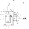
図1は、実施形態1に係るガス絶縁変圧システム100の構成を示す図である。図1に示すように、ガス絶縁変圧システム100は、変圧器1(ガス絶縁変圧器)および一次電圧推定装置9を備える。図2及び図3は、変圧器1の容器31内部に配置される主要部材の特定の切断位置での断面を示す。 (Configuration of Gas Insulated Transformer System 100)
FIG. 1 is a diagram showing a configuration of a gas-insulatedtransformer system 100 according to the first embodiment. As shown in FIG. 1, the gas-insulated transformer system 100 includes a transformer 1 (gas-insulated transformer) and a primary voltage estimation device 9. 2 and 3 show a cross section of a main member arranged inside the container 31 of the transformer 1 at a specific cutting position.
図1は、実施形態1に係るガス絶縁変圧システム100の構成を示す図である。図1に示すように、ガス絶縁変圧システム100は、変圧器1(ガス絶縁変圧器)および一次電圧推定装置9を備える。図2及び図3は、変圧器1の容器31内部に配置される主要部材の特定の切断位置での断面を示す。 (Configuration of Gas Insulated Transformer System 100)
FIG. 1 is a diagram showing a configuration of a gas-insulated
図2は、図1におけるX-X線での断面を示す。図3は、図2におけるY-Y線での断面を示す。このようなガス絶縁変圧システム100は、例えば、高圧の電力を変換し、所内電力として供給する目的で、発電所や変電所に設置される。また、図4は、変圧器1の回路の概略構成を示す回路図である。
FIG. 2 shows a cross section taken along line XX in FIG. FIG. 3 shows a cross section taken along the line YY in FIG. Such a gas-insulated transformer system 100 is installed in a power plant or a substation for the purpose of converting high-voltage electric power and supplying it as in-house electric power, for example. Further, FIG. 4 is a circuit diagram showing a schematic configuration of the circuit of the transformer 1.
(変圧器1の構成)
変圧器1は、単相接地型の変圧器である。変圧器1は、コア10、一次巻線11、二次巻線12、高圧シールド13、低圧シールド14、リード接続部16、コンデンサ21(回路素子)、電圧検出端子22、接地端子23、電圧検出器24、容器31、および端子箱32を備える。 (Configuration of transformer 1)
The transformer 1 is a single-phase grounded transformer. The transformer 1 includes acore 10, a primary winding 11, a secondary winding 12, a high voltage shield 13, a low voltage shield 14, a lead connection portion 16, a capacitor 21 (circuit element), a voltage detection terminal 22, a ground terminal 23, and a voltage detection. It includes a vessel 24, a container 31, and a terminal box 32.
変圧器1は、単相接地型の変圧器である。変圧器1は、コア10、一次巻線11、二次巻線12、高圧シールド13、低圧シールド14、リード接続部16、コンデンサ21(回路素子)、電圧検出端子22、接地端子23、電圧検出器24、容器31、および端子箱32を備える。 (Configuration of transformer 1)
The transformer 1 is a single-phase grounded transformer. The transformer 1 includes a
コア10は、一次巻線11および二次巻線12が巻回される芯材である。コア10は磁性体を含む材料により形成される。実施形態1では、コア10は鉄で形成されている。二次巻線12は、コア10に巻回されている。一次巻線11は、二次巻線12の外周外に、二次巻線12と同軸に巻回されている。
The core 10 is a core material around which the primary winding 11 and the secondary winding 12 are wound. The core 10 is formed of a material containing a magnetic material. In the first embodiment, the core 10 is made of iron. The secondary winding 12 is wound around the core 10. The primary winding 11 is wound coaxially with the secondary winding 12 outside the outer circumference of the secondary winding 12.
変圧器1においては、一次巻線11の入力端子(図4の回路図における端子U、V)に一次電圧V1を入力することで、一次巻線11と二次巻線12との巻数比に応じた二次電圧が、二次巻線12の出力端子(図4の回路図における端子u、v)から出力される。一次巻線11および二次巻線12の巻数比は、所望の一次電圧V1と二次電圧との比率に応じて適宜決定されればよい。
In the transformer 1, by inputting the primary voltage V1 to the input terminals of the primary winding 11 (terminals U and V in the circuit diagram of FIG. 4), the turns ratio between the primary winding 11 and the secondary winding 12 can be obtained. The corresponding secondary voltage is output from the output terminal of the secondary winding 12 (terminals u and v in the circuit diagram of FIG. 4). The turns ratio of the primary winding 11 and the secondary winding 12 may be appropriately determined according to the ratio of the desired primary voltage V1 to the secondary voltage.
高圧シールド13は、一次巻線11の外周を覆う。高圧シールド13は、一次巻線11に、変電所等の母線または線路等から供給される一次電圧V1が印加されることで生じる電界の影響を緩和する。低圧シールド14は、高圧シールド13に対向する位置に設けられる。具体的には、低圧シールド14は、高圧シールド13と、コア10の二次巻線12に覆われない領域との間に配される。
The high voltage shield 13 covers the outer circumference of the primary winding 11. The high-voltage shield 13 alleviates the influence of the electric field generated by applying the primary voltage V1 supplied from a bus or a line of a substation or the like to the primary winding 11. The low voltage shield 14 is provided at a position facing the high voltage shield 13. Specifically, the low voltage shield 14 is arranged between the high voltage shield 13 and a region not covered by the secondary winding 12 of the core 10.
低圧シールド14は、上記の位置に設けられることで、コア10のエッジ、および、コア10の固定具といった部材が一次巻線11による電界に与える影響を軽減するものである。また、二次巻線12の軸方向は、一次巻線11の軸方向よりも長い。このため、変圧器1においては、二次巻線12も、コア10のエッジ、および、コア10の固定具といった部材が一次巻線11による電界に与える影響を軽減するシールドとして作用する。
The low voltage shield 14 is provided at the above position to reduce the influence of members such as the edge of the core 10 and the fixture of the core 10 on the electric field due to the primary winding 11. Further, the axial direction of the secondary winding 12 is longer than the axial direction of the primary winding 11. Therefore, in the transformer 1, the secondary winding 12 also acts as a shield that reduces the influence of members such as the edge of the core 10 and the fixture of the core 10 on the electric field due to the primary winding 11.
高圧シールド13および低圧シールド14は、いずれも導体により形成される。また、高圧シールド13および低圧シールド14は、互いに導体で接続されることはない。低圧シールド14は、高圧シールド13に対向する位置に設けられているため、変圧器1においては、高圧シールド13と低圧シールド14との間に静電容量C1が存在する。以下の説明においては、高圧シールド13と低圧シールド14とが、上記静電容量C1を有する仮想コンデンサ15を介して互いに接続されているものとする。
Both the high-voltage shield 13 and the low-voltage shield 14 are formed of conductors. Further, the high voltage shield 13 and the low voltage shield 14 are not connected to each other by a conductor. Since the low voltage shield 14 is provided at a position facing the high voltage shield 13, the capacitance C1 exists between the high voltage shield 13 and the low voltage shield 14 in the transformer 1. In the following description, it is assumed that the high voltage shield 13 and the low voltage shield 14 are connected to each other via the virtual capacitor 15 having the capacitance C1.
リード接続部16は、二次巻線12のリード12aが接続される部材である。図1に示すように、変圧器1において、低圧シールド14は、高圧シールド13とリード接続部16との間に配される。このため、低圧シールド14は、リード接続部16が一次巻線11による電界に与える影響についても軽減する。
The lead connection portion 16 is a member to which the lead 12a of the secondary winding 12 is connected. As shown in FIG. 1, in the transformer 1, the low voltage shield 14 is arranged between the high voltage shield 13 and the lead connection portion 16. Therefore, the low voltage shield 14 also reduces the influence of the lead connection portion 16 on the electric field due to the primary winding 11.
コンデンサ21は、一端が低圧シールド14に接続され、他端が接地端子23に接続される回路素子である。接地端子23は、コンデンサ21を接地する端子である。したがって、低圧シールド14の電位は、コンデンサ21に印加される電圧の分だけ、接地電位から浮いた状態である。
The capacitor 21 is a circuit element having one end connected to the low voltage shield 14 and the other end connected to the ground terminal 23. The ground terminal 23 is a terminal for grounding the capacitor 21. Therefore, the potential of the low voltage shield 14 is in a state of floating from the ground potential by the amount of the voltage applied to the capacitor 21.
電圧検出端子22は、コンデンサ21に印加される電圧Vmを検出するための端子である。電圧検出端子22は、コンデンサ21の、低圧シールド14に接続されている一端に接続されている。このため、変圧器1においては、電圧検出端子22と接地端子23とにより、コンデンサ21に印加される電圧Vmを検出することができる。
The voltage detection terminal 22 is a terminal for detecting the voltage Vm applied to the capacitor 21. The voltage detection terminal 22 is connected to one end of the capacitor 21 connected to the low voltage shield 14. Therefore, in the transformer 1, the voltage Vm applied to the capacitor 21 can be detected by the voltage detection terminal 22 and the ground terminal 23.
電圧検出器24は、コンデンサ21に印加される電圧Vmを検出する。電圧検出器24は、電圧検出端子22と、接地端子23との間に接続されている。換言すれば、電圧検出器24は、コンデンサ21の、低圧シールド14に接続されている一端と、接地端子23との間に接続されている。これにより、電圧検出器24はコンデンサ21に印加される電圧Vmを検出できる。電圧検出器24としては、公知の検出器を用いることができる。実施形態1においては、変圧器1が電圧検出器を備えるため、電圧検出器を別途接続する必要がない。
The voltage detector 24 detects the voltage Vm applied to the capacitor 21. The voltage detector 24 is connected between the voltage detection terminal 22 and the ground terminal 23. In other words, the voltage detector 24 is connected between one end of the capacitor 21 connected to the low voltage shield 14 and the ground terminal 23. As a result, the voltage detector 24 can detect the voltage Vm applied to the capacitor 21. As the voltage detector 24, a known detector can be used. In the first embodiment, since the transformer 1 includes a voltage detector, it is not necessary to separately connect the voltage detector.
容器31は、コア10、一次巻線11、二次巻線12、高圧シールド13および低圧シールド14を密閉状態で収容する。容器31内には、絶縁用のガスとして、例えば0.55MPaのSF6が充填される。ただし、容器31に充填されるガスの圧力および種類はこれに限らない。
The container 31 houses the core 10, the primary winding 11, the secondary winding 12, the high-voltage shield 13 and the low-voltage shield 14 in a sealed state. The container 31 is filled with, for example, 0.55 MPa of SF 6 as an insulating gas. However, the pressure and type of gas filled in the container 31 are not limited to this.
一次巻線11に一次電圧V1を入力するための非接地側の端子11aは、ブッシング33を介して容器31から引き出された位置に設けられている。また、ブッシング33の代わりに、絶縁樹脂により形成された本体と、当該本体を貫通して設けられた埋め込み導体とを有する、絶縁スペーサを用いてもよい。端子11aは、接続導体11bにより、一次巻線11に接続されている。
The terminal 11a on the non-grounded side for inputting the primary voltage V1 to the primary winding 11 is provided at a position drawn out from the container 31 via the bushing 33. Further, instead of the bushing 33, an insulating spacer having a main body formed of an insulating resin and an embedded conductor provided so as to penetrate the main body may be used. The terminal 11a is connected to the primary winding 11 by a connecting conductor 11b.
端子箱32は、さらに、一次巻線11および二次巻線12に対するその他の入出力端子を収容する。端子箱32には、一次巻線11の、上述した端子11aとは逆側の入力端子(図4の回路図における端子V)、および、リード接続部16を介して二次巻線12のそれぞれのリード12aに接続される出力端子(同、端子u及び端子v)が収容されている。
The terminal box 32 further accommodates other input / output terminals for the primary winding 11 and the secondary winding 12. In the terminal box 32, the input terminal (terminal V in the circuit diagram of FIG. 4) of the primary winding 11 opposite to the terminal 11a described above, and the secondary winding 12 via the lead connection portion 16 respectively. The output terminal (same as the terminal u and the terminal v) connected to the lead 12a of the above is accommodated.
これらの端子、ならびに、当該端子と一次巻線11および二次巻線12とを接続するリード線については煩雑さを避けるため図1には示されていない。容器31とは異なり、端子箱32には絶縁用のガスが充填されている必要はない。
These terminals and the lead wires connecting the terminals to the primary winding 11 and the secondary winding 12 are not shown in FIG. 1 to avoid complication. Unlike the container 31, the terminal box 32 does not need to be filled with an insulating gas.
また、容器31には、低圧シールド14に接続されているリード線を容器31内から端子箱32内へ引き出すための引き出し部材34が設けられている。コンデンサ21は、端子箱32内に配される。すなわち、コンデンサ21は、容器31の外部に配される。このため、コンデンサ21に不具合が生じた場合に、絶縁用のガスが充填されている容器31を開放することなく当該不具合に対応できる。
Further, the container 31 is provided with a pull-out member 34 for pulling out the lead wire connected to the low-voltage shield 14 from the inside of the container 31 into the terminal box 32. The capacitor 21 is arranged in the terminal box 32. That is, the capacitor 21 is arranged outside the container 31. Therefore, when a defect occurs in the capacitor 21, the defect can be dealt with without opening the container 31 filled with the insulating gas.
(一次電圧の検出)
図4に示すように、変圧器1においては、静電容量C1を有する仮想コンデンサ15、および、静電容量C2を有するコンデンサ21により、非接地である高圧シールド13に誘起される一次電圧V1の分圧回路が形成される。 (Detection of primary voltage)
As shown in FIG. 4, in the transformer 1, the primary voltage V1 induced in the ungrounded high-voltage shield 13 by the virtual capacitor 15 having the capacitance C1 and the capacitor 21 having the capacitance C2. A voltage divider circuit is formed.
図4に示すように、変圧器1においては、静電容量C1を有する仮想コンデンサ15、および、静電容量C2を有するコンデンサ21により、非接地である高圧シールド13に誘起される一次電圧V1の分圧回路が形成される。 (Detection of primary voltage)
As shown in FIG. 4, in the transformer 1, the primary voltage V1 induced in the ungrounded high-
静電容量C1の値は、高圧シールド13および低圧シールド14の大きさおよび形状、ならびに容器31内に充填されるガスの種類および圧力などに応じて一意に定まる既知の値である。また、静電容量C2の値が既知であることは言うまでもない。
The value of the capacitance C1 is a known value uniquely determined according to the size and shape of the high pressure shield 13 and the low pressure shield 14, the type and pressure of the gas filled in the container 31, and the like. Needless to say, the value of the capacitance C2 is known.
その結果、電圧検出器24が検出する、コンデンサ21に印加される電圧Vmは、高圧シールド13に誘起される一次電圧V1を、仮想コンデンサ15とコンデンサ21とのインピーダンス比で按分した値となる。すなわち、ωを一次電圧V1の角周波数として、関係式Vm=V1×{1/(j×ω×C2)}/{1/(j×ω×C1)+1/(j×ω×C2)}が成立する。よって一次電圧V1は、関係式V1=Vm×(C1+C2)/C1により算出される。したがって、変圧器1においては、コンデンサ21に印加される電圧Vmを電圧検出端子22により測定することで、一次巻線11に印加されている一次電圧V1を推定することができる。
As a result, the voltage Vm applied to the capacitor 21 detected by the voltage detector 24 is a value obtained by proportionally dividing the primary voltage V1 induced in the high-voltage shield 13 by the impedance ratio between the virtual capacitor 15 and the capacitor 21. That is, with ω as the angular frequency of the primary voltage V1, the relational expression Vm = V1 × {1 / (j × ω × C2)} / {1 / (j × ω × C1) + 1 / (j × ω × C2)} Is established. Therefore, the primary voltage V1 is calculated by the relational expression V1 = Vm × (C1 + C2) / C1. Therefore, in the transformer 1, the primary voltage V1 applied to the primary winding 11 can be estimated by measuring the voltage Vm applied to the capacitor 21 by the voltage detection terminal 22.
図5は、一次電圧推定装置9の要部の構成を示すブロック図である。一次電圧推定装置9は、電圧検出器24が検出する電圧に基づいて、一次電圧V1の大きさを推定する。図5に示すように、一次電圧推定装置9は、回路素子電圧検出部91および一次電圧推定部92を備える。
FIG. 5 is a block diagram showing a configuration of a main part of the primary voltage estimation device 9. The primary voltage estimation device 9 estimates the magnitude of the primary voltage V1 based on the voltage detected by the voltage detector 24. As shown in FIG. 5, the primary voltage estimation device 9 includes a circuit element voltage detection unit 91 and a primary voltage estimation unit 92.
回路素子電圧検出部91は、コンデンサ21に印加される電圧Vmを、電圧検出器24により検出する。回路素子電圧検出部91は、電圧Vmを示す信号を、一次電圧推定部92へ出力する。
The circuit element voltage detection unit 91 detects the voltage Vm applied to the capacitor 21 by the voltage detector 24. The circuit element voltage detection unit 91 outputs a signal indicating the voltage Vm to the primary voltage estimation unit 92.
一次電圧推定部92は、仮想コンデンサ15の静電容量C1と、コンデンサ21の静電容量(回路定数)C2と、コンデンサ21に印加される電圧Vmとに基づいて、一次電圧V1を上記の関係式により算出する。したがって、ガス絶縁変圧システム100においては、一次電圧推定装置9により一次電圧V1を推定できる。
The primary voltage estimation unit 92 determines the primary voltage V1 in the above relationship based on the capacitance C1 of the virtual capacitor 15, the capacitance (circuit constant) C2 of the capacitor 21, and the voltage Vm applied to the capacitor 21. Calculated by the formula. Therefore, in the gas isolated transformer system 100, the primary voltage V1 can be estimated by the primary voltage estimation device 9.
図6は、一次電圧推定装置9が一次電圧V1を推定する処理を示すフローチャートである。一次電圧V1を推定する処理において、まず、回路素子電圧検出部91は、コンデンサ21に印加される電圧Vmを検出する(S1)。次に、一次電圧推定部92は、一次電圧V1を推定する(S2)。
FIG. 6 is a flowchart showing a process in which the primary voltage estimation device 9 estimates the primary voltage V1. In the process of estimating the primary voltage V1, the circuit element voltage detection unit 91 first detects the voltage Vm applied to the capacitor 21 (S1). Next, the primary voltage estimation unit 92 estimates the primary voltage V1 (S2).
以上のとおり、実施形態1に係る変圧器1では、コンデンサ21に印加される電圧Vmを測定することで、一次電圧V1を推定することができる。コンデンサ21に印加される電圧Vmは、二次巻線12に接続される負荷によらず一定である。
As described above, in the transformer 1 according to the first embodiment, the primary voltage V1 can be estimated by measuring the voltage Vm applied to the capacitor 21. The voltage Vm applied to the capacitor 21 is constant regardless of the load connected to the secondary winding 12.
変圧器においては、出力用の二次巻線とは別に、電圧検出用の巻線をコアに巻回し、電圧検出用の巻線に印加された電圧から、一次電圧を検知することが検討されている。しかし、電圧検出用の巻線に印加される電圧は、二次巻線を流れる負荷電流によっても変動する。
In a transformer, it is considered to wind a winding for voltage detection around the core separately from the secondary winding for output, and detect the primary voltage from the voltage applied to the winding for voltage detection. ing. However, the voltage applied to the winding for voltage detection also fluctuates depending on the load current flowing through the secondary winding.
例えば、変圧器1と同様の構成であるが、電圧検出用の巻線を設けて一次電圧を検知する方法では、実際の使用条件において負荷によって、5~10%程度の誤差が生じてしまうことが判明した。
For example, although the configuration is the same as that of the transformer 1, in the method of detecting the primary voltage by providing a winding for voltage detection, an error of about 5 to 10% may occur depending on the load under actual usage conditions. There was found.
しかし、本実施形態に係る変圧器1は、上記方法により一次電圧V1を検知するため、負荷の変動による誤差は生じない。したがって、変圧器1においては、一次電圧V1を高い精度で推定することができる。また、電圧測定のための巻線を備える必要は無く、変圧器の構成も単純なものとできる。
However, since the transformer 1 according to the present embodiment detects the primary voltage V1 by the above method, no error occurs due to the fluctuation of the load. Therefore, in the transformer 1, the primary voltage V1 can be estimated with high accuracy. Further, it is not necessary to provide a winding for voltage measurement, and the configuration of the transformer can be simplified.
あるいは変圧器において、一次電圧V1測定のための変成器を変圧器1の一次側に並列に一体に設けることも検討されている。しかしそのような構成の変圧器は、構成が複雑であり、装置が大型化する。
Alternatively, in a transformer, it is also considered to integrally provide a transformer for measuring the primary voltage V1 in parallel on the primary side of the transformer 1. However, a transformer having such a configuration is complicated in configuration and the equipment becomes large.
また、変圧器とは別途、一次電圧V1測定のための変成器を変圧器1の一次側に並列に設けるとしても、ガス絶縁変圧システム100として大型化し、かつ高コスト化することは言うまでもない。一方、本実施形態によれば、ガス絶縁変圧システム100として、コンパクトであり、また低コストな構成で一次電圧V1を検知し得る。
It goes without saying that even if a transformer for measuring the primary voltage V1 is provided in parallel on the primary side of the transformer 1 separately from the transformer, the size and cost of the gas-insulated transformer system 100 will increase. On the other hand, according to the present embodiment, the gas-insulated transformer system 100 can detect the primary voltage V1 in a compact and low-cost configuration.
この他、ガス絶縁変圧システム100は、回路素子電圧検出部91が検出した電圧Vm、および一次電圧推定部92が推定した一次電圧V1のうち1以上をユーザに対して出力する出力装置を備えてもよい。出力装置の例としては、画像を表示する表示装置が挙げられる。
In addition, the gas-insulated transformer system 100 includes an output device that outputs one or more of the voltage Vm detected by the circuit element voltage detection unit 91 and the primary voltage V1 estimated by the primary voltage estimation unit 92 to the user. May be good. An example of an output device is a display device that displays an image.
また、ガス絶縁変圧システム100は、一次電圧推定部92が推定した一次電圧V1が所定の範囲内であるか判定し、所定の範囲内でない場合にはユーザに対して警報を発する警報装置を備えていてもよい。警報は、例えば画像、光、または音によるものである。
Further, the gas-insulated transformer system 100 includes an alarm device that determines whether the primary voltage V1 estimated by the primary voltage estimation unit 92 is within a predetermined range and issues an alarm to the user if the primary voltage V1 is not within the predetermined range. May be. The alarm is, for example, an image, light, or sound.
〔実施形態2〕
本発明の他の実施形態について、以下に説明する。なお、説明の便宜上、上記実施形態にて説明した部材と同じ機能を有する部材については、同じ符号を付記し、その説明を繰り返さない。 [Embodiment 2]
Other embodiments of the present invention will be described below. For convenience of explanation, the same reference numerals are given to the members having the same functions as the members described in the above-described embodiment, and the description thereof will not be repeated.
上述したとおり、実施形態1に係る変圧器1は、電圧Vmを検出するための回路素子としてコンデンサ21を備える。しかし、本発明に係る変圧器は、コンデンサ21の代わりに、抵抗器またはインダクタといった、別種の回路素子を備えていてもよい。
As described above, the transformer 1 according to the first embodiment includes a capacitor 21 as a circuit element for detecting the voltage Vm. However, the transformer according to the present invention may include another kind of circuit element such as a resistor or an inductor instead of the capacitor 21.
このような変圧器においても、仮想コンデンサ15および回路素子により分圧回路が形成される。このため、回路素子に印加される電圧Vmに基づいて一次電圧V1を推定することができる。ただし、上記の関係式による一次電圧V1の算出を簡素化する観点からは、印加電圧によって決まる鉄心の励磁電流及び二次に接続される負荷の大きさによって決まる負荷電流に一次電圧V1が影響されないよう、回路素子をコンデンサとすることが好ましい。
Even in such a transformer, a voltage dividing circuit is formed by the virtual capacitor 15 and circuit elements. Therefore, the primary voltage V1 can be estimated based on the voltage Vm applied to the circuit element. However, from the viewpoint of simplifying the calculation of the primary voltage V1 by the above relational expression, the primary voltage V1 is not affected by the exciting current of the iron core determined by the applied voltage and the load current determined by the magnitude of the load connected secondarily. Therefore, it is preferable that the circuit element is a capacitor.
〔ソフトウェアによる実現例〕
一次電圧推定装置9の制御ブロック(特に回路素子電圧検出部91および一次電圧推定部92)は、集積回路(ICチップ)等に形成された論理回路(ハードウェア)によって実現してもよいし、ソフトウェアによって実現してもよい。 [Example of implementation by software]
The control block of the primary voltage estimation device 9 (particularly, the circuit elementvoltage detection unit 91 and the primary voltage estimation unit 92) may be realized by a logic circuit (software) formed in an integrated circuit (IC chip) or the like. It may be realized by software.
一次電圧推定装置9の制御ブロック(特に回路素子電圧検出部91および一次電圧推定部92)は、集積回路(ICチップ)等に形成された論理回路(ハードウェア)によって実現してもよいし、ソフトウェアによって実現してもよい。 [Example of implementation by software]
The control block of the primary voltage estimation device 9 (particularly, the circuit element
後者の場合、一次電圧推定装置9は、各機能を実現するソフトウェアであるプログラムの命令を実行するコンピュータを備えている。このコンピュータは、例えば少なくとも1つのプロセッサ(制御装置)を備えていると共に、上記プログラムを記憶したコンピュータ読み取り可能な少なくとも1つの記録媒体を備えている。
In the latter case, the primary voltage estimation device 9 includes a computer that executes a program instruction, which is software that realizes each function. This computer includes, for example, at least one processor (control device) and at least one computer-readable recording medium in which the program is stored.
そして、上記コンピュータにおいて、上記プロセッサが上記プログラムを上記記録媒体から読み取って実行することにより、本発明の目的が達成される。上記プロセッサとしては、例えばCPU(Central Processing Unit)を用いることができる。上記記録媒体としては、「一時的でない有形の媒体」、例えば、ROM(Read Only Memory)等の他、テープ、ディスク、カード、半導体メモリ、プログラマブルな論理回路などを用いることができる。
Then, in the computer, the processor reads the program from the recording medium and executes it, thereby achieving the object of the present invention. As the processor, for example, a CPU (Central Processing Unit) can be used. As the recording medium, a “non-temporary tangible medium”, for example, a ROM (Read Only Memory) or the like, a tape, a disk, a card, a semiconductor memory, a programmable logic circuit, or the like can be used.
また、上記プログラムを展開するRAM(Random Access Memory)などをさらに備えていてもよい。また、上記プログラムは、該プログラムを伝送可能な任意の伝送媒体(通信ネットワークや放送波等)を介して上記コンピュータに供給されてもよい。なお、本発明の一態様は、上記プログラムが電子的な伝送によって具現化された、搬送波に埋め込まれたデータ信号の形態でも実現され得る。
Further, a RAM (RandomAccessMemory) for expanding the above program may be further provided. Further, the program may be supplied to the computer via any transmission medium (communication network, broadcast wave, etc.) capable of transmitting the program. It should be noted that one aspect of the present invention can also be realized in the form of a data signal embedded in a carrier wave, in which the above program is embodied by electronic transmission.
〔まとめ〕
本発明の態様1に係るガス絶縁変圧器は、コアと、前記コアに巻回された二次巻線と、前記二次巻線の外周外に前記二次巻線と同軸に巻回された一次巻線と、前記一次巻線の外周を覆う高圧シールドと、前記高圧シールドに対向する低圧シールドと、接地端子と、一端が前記低圧シールドに接続され、他端が前記接地端子に接続される回路素子と、を備える。 〔summary〕
The gas-insulated transformer according to the first aspect of the present invention is wound coaxially with the core, the secondary winding wound around the core, and the outer periphery of the secondary winding. The primary winding, the high-voltage shield covering the outer periphery of the primary winding, the low-voltage shield facing the high-voltage shield, the ground terminal, one end is connected to the low-voltage shield, and the other end is connected to the ground terminal. It is equipped with a circuit element.
上記の構成によれば、高圧シールドおよび低圧シールドにより形成される仮想的なコンデンサと、低圧シールドおよび接地端子に接続される回路素子とにより、分圧回路が形成される。回路素子に印加される電圧を検出することで、高圧シールドに誘起される一次電圧を算出できる。したがって、ガス絶縁変圧器を大型化させることなく、負荷電流に影響されずに、一次電圧を推定できる機能を付加することができる。
According to the above configuration, a voltage dividing circuit is formed by a virtual capacitor formed by a high voltage shield and a low voltage shield, and a circuit element connected to the low voltage shield and a ground terminal. By detecting the voltage applied to the circuit element, the primary voltage induced in the high voltage shield can be calculated. Therefore, it is possible to add a function that can estimate the primary voltage without increasing the size of the gas-insulated transformer and without being affected by the load current.
また、本発明の態様2に係るガス絶縁変圧器は、態様1において、前記二次巻線の軸方向は、前記一次巻線の軸方向よりも長い。
Further, in the gas-insulated transformer according to the second aspect of the present invention, in the first aspect, the axial direction of the secondary winding is longer than the axial direction of the primary winding.
上記の構成によれば、二次巻線が、コアのエッジおよび固定具といった部材が一次巻線による電界に与える影響を軽減するシールドとして作用する。
According to the above configuration, the secondary winding acts as a shield that reduces the influence of members such as the edge of the core and the fixture on the electric field due to the primary winding.
また、本発明の態様3に係るガス絶縁変圧器は、態様2において、前記低圧シールドは、前記高圧シールドと、前記コアの前記二次巻線に覆われない領域との間に配される。
Further, in the gas insulated transformer according to the third aspect of the present invention, in the second aspect, the low voltage shield is arranged between the high voltage shield and the region not covered by the secondary winding of the core.
上記の構成によれば、低圧シールドにより、コアのエッジおよび固定具といった部材が一次巻線による電界に与える影響を軽減できる。
According to the above configuration, the low voltage shield can reduce the influence of members such as the edge of the core and the fixture on the electric field due to the primary winding.
また、本発明の態様4に係るガス絶縁変圧器は、態様2または3において、前記二次巻線のリードが接続されるリード接続部を更に備え、前記低圧シールドは、前記高圧シールドと前記リード接続部との間に配される。
Further, the gas-insulated transformer according to the fourth aspect of the present invention further includes a lead connection portion to which the leads of the secondary winding are connected in the second or third aspect, and the low voltage shield is the high voltage shield and the lead. It is placed between the connection part.
上記の構成によれば、低圧シールドにより、リード接続部が一次巻線11による電界に与える影響についても軽減できる。
According to the above configuration, the low voltage shield can also reduce the influence of the lead connection portion on the electric field due to the primary winding 11.
また、本発明の態様5に係るガス絶縁変圧器は、態様1から4のいずれかにおいて、前記回路素子の前記一端と、前記接地端子との間に接続された電圧検出器をさらに備える。
Further, the gas-insulated transformer according to the fifth aspect of the present invention further includes a voltage detector connected between the one end of the circuit element and the ground terminal in any one of the first to fourth aspects.
上記の構成によれば、回路素子に印加される電圧を検出する電圧検出器を別途接続する必要がなくなる。
According to the above configuration, it is not necessary to separately connect a voltage detector that detects the voltage applied to the circuit element.
また、本発明の態様6に係るガス絶縁変圧システムは、態様5のガス絶縁変圧器と、前記電圧検出器が検出する電圧に基づいて、一次電圧の大きさを推定する、一次電圧推定装置と、を備える。
Further, the gas-insulated transformer system according to the sixth aspect of the present invention includes the gas-insulated transformer of the fifth aspect and a primary voltage estimation device that estimates the magnitude of the primary voltage based on the voltage detected by the voltage detector. , Equipped with.
上記の構成によれば、一次電圧推定装置により一次電圧を推定できる。
According to the above configuration, the primary voltage can be estimated by the primary voltage estimation device.
また、本発明の態様7に係る電圧推定方法は、コアと、前記コアに巻回された二次巻線と、前記二次巻線の外周外に前記二次巻線と同軸に巻回された一次巻線と、前記一次巻線の外周を覆う高圧シールドと、前記高圧シールドに対向する低圧シールドと、接地端子と、一端が前記低圧シールドに接続され、他端が前記接地端子に接続される回路素子と、を備えるガス絶縁変圧器の、一次電圧を推定する電圧推定方法であって、前記回路素子に印加される電圧を検出するステップと、前記高圧シールドと前記低圧シールドとの間の静電容量と、前記回路素子の回路定数と、前記回路素子に印加される電圧とに基づいて、一次電圧を推定するステップと、を含む。
Further, in the voltage estimation method according to the seventh aspect of the present invention, the core, the secondary winding wound around the core, and the secondary winding are wound coaxially with the secondary winding outside the outer periphery of the secondary winding. A primary winding, a high-voltage shield covering the outer periphery of the primary winding, a low-voltage shield facing the high-voltage shield, a ground terminal, one end connected to the low-voltage shield, and the other end connected to the ground terminal. A voltage estimation method for estimating the primary voltage of a gas-insulated transformer comprising the circuit element, between the step of detecting the voltage applied to the circuit element and the high-voltage shield and the low-voltage shield. It includes a step of estimating the primary voltage based on the capacitance, the circuit constant of the circuit element, and the voltage applied to the circuit element.
上記の構成によれば、電圧推定方法において、まず、低圧シールドと接地端子とに接続される回路素子の電圧を検出し、当該電圧に基づいて一次電圧を推定する。したがって、一次電圧を直接測定するのではなく、推定することで検知できる。
According to the above configuration, in the voltage estimation method, first, the voltage of the circuit element connected to the low voltage shield and the ground terminal is detected, and the primary voltage is estimated based on the voltage. Therefore, it can be detected by estimating the primary voltage rather than directly measuring it.
本発明は上述した各実施形態に限定されるものではなく、請求項に示した範囲で種々の変更が可能であり、異なる実施形態にそれぞれ開示された技術的手段を適宜組み合わせて得られる実施形態についても本発明の技術的範囲に含まれる。さらに、各実施形態にそれぞれ開示された技術的手段を組み合わせることにより、新しい技術的特徴を形成することができる。
The present invention is not limited to the above-described embodiments, and various modifications can be made within the scope of the claims, and the embodiments obtained by appropriately combining the technical means disclosed in the different embodiments. Is also included in the technical scope of the present invention. Further, by combining the technical means disclosed in each embodiment, new technical features can be formed.
1 変圧器
9 一次電圧推定装置
10 コア
11 一次巻線
12 二次巻線
13 高圧シールド
14 低圧シールド
16 リード接続部
21 コンデンサ(回路素子)
22 電圧検出端子
23 接地端子
24 電圧検出器
31 容器
100 ガス絶縁変圧システム
1Transformer 9 Primary voltage estimator 10 Core 11 Primary winding 12 Secondary winding 13 High voltage shield 14 Low voltage shield 16 Lead connection 21 Capacitor (circuit element)
22Voltage detection terminal 23 Grounding terminal 24 Voltage detector 31 Container 100 Gas insulation transformer system
9 一次電圧推定装置
10 コア
11 一次巻線
12 二次巻線
13 高圧シールド
14 低圧シールド
16 リード接続部
21 コンデンサ(回路素子)
22 電圧検出端子
23 接地端子
24 電圧検出器
31 容器
100 ガス絶縁変圧システム
1
22
Claims (7)
- コアと、
前記コアに巻回された二次巻線と、
前記二次巻線の外周外に前記二次巻線と同軸に巻回された一次巻線と、
前記一次巻線の外周を覆う高圧シールドと、
前記高圧シールドに対向する低圧シールドと、
接地端子と、
一端が前記低圧シールドに接続され、他端が前記接地端子に接続される回路素子と、を備えることを特徴とする、ガス絶縁変圧器。 With the core
The secondary winding wound around the core and
A primary winding coaxially wound with the secondary winding outside the outer circumference of the secondary winding,
A high-voltage shield that covers the outer circumference of the primary winding,
A low-voltage shield facing the high-voltage shield and
Grounding terminal and
A gas-insulated transformer comprising: a circuit element having one end connected to the low voltage shield and the other end connected to the ground terminal. - 前記二次巻線の軸方向は、前記一次巻線の軸方向よりも長いことを特徴とする、請求項1に記載のガス絶縁変圧器。 The gas-insulated transformer according to claim 1, wherein the axial direction of the secondary winding is longer than the axial direction of the primary winding.
- 前記低圧シールドは、前記高圧シールドと、前記コアの前記二次巻線に覆われない領域との間に配されることを特徴とする、請求項2に記載のガス絶縁変圧器。 The gas-insulated transformer according to claim 2, wherein the low-voltage shield is arranged between the high-voltage shield and a region of the core that is not covered by the secondary winding.
- 前記二次巻線のリードが接続されるリード接続部を更に備え、
前記低圧シールドは、前記高圧シールドと前記リード接続部との間に配されることを特徴とする、請求項2または3に記載のガス絶縁変圧器。 Further provided with a lead connection to which the leads of the secondary winding are connected,
The gas-insulated transformer according to claim 2 or 3, wherein the low-voltage shield is arranged between the high-voltage shield and the lead connection portion. - 前記回路素子の前記一端と、前記接地端子との間に接続された電圧検出器をさらに備えることを特徴とする、請求項1から4のいずれか1項に記載のガス絶縁変圧器。 The gas-insulated transformer according to any one of claims 1 to 4, further comprising a voltage detector connected between the one end of the circuit element and the ground terminal.
- 請求項5に記載のガス絶縁変圧器と、
前記電圧検出器が検出する電圧に基づいて、一次電圧の大きさを推定する、一次電圧推定装置と、を備えることを特徴とする、ガス絶縁変圧システム。 The gas-insulated transformer according to claim 5 and
A gas-insulated transformer system comprising a primary voltage estimation device that estimates the magnitude of a primary voltage based on a voltage detected by the voltage detector. - コアと、
前記コアに巻回された二次巻線と、
前記二次巻線の外周外に前記二次巻線と同軸に巻回された一次巻線と、
前記一次巻線の外周を覆う高圧シールドと、
前記高圧シールドに対向する低圧シールドと、
接地端子と、
一端が前記低圧シールドに接続され、他端が前記接地端子に接続される回路素子と、を備えるガス絶縁変圧器の、一次電圧を推定する電圧推定方法であって、
前記回路素子に印加される電圧を検出するステップと、
前記高圧シールドと前記低圧シールドとの間の静電容量と、前記回路素子の回路定数と、前記回路素子に印加される電圧とに基づいて、一次電圧を推定するステップと、を含むことを特徴とする、電圧推定方法。 With the core
The secondary winding wound around the core and
A primary winding coaxially wound with the secondary winding outside the outer circumference of the secondary winding,
A high-voltage shield that covers the outer circumference of the primary winding,
A low-voltage shield facing the high-voltage shield and
Grounding terminal and
A voltage estimation method for estimating the primary voltage of a gas-insulated transformer comprising a circuit element having one end connected to the low voltage shield and the other end connected to the ground terminal.
The step of detecting the voltage applied to the circuit element and
It is characterized by including a step of estimating a primary voltage based on a capacitance between the high voltage shield and the low voltage shield, a circuit constant of the circuit element, and a voltage applied to the circuit element. The voltage estimation method.
Priority Applications (3)
| Application Number | Priority Date | Filing Date | Title |
|---|---|---|---|
| CN202080102331.XA CN115702464A (en) | 2020-06-25 | 2020-06-25 | Gas-insulated transformer, gas-insulated transformer system, and voltage estimation method |
| PCT/JP2020/024974 WO2021260874A1 (en) | 2020-06-25 | 2020-06-25 | Gas insulated transformer, gas insulated transformer system and voltage estimation method |
| JP2022532172A JPWO2021260874A1 (en) | 2020-06-25 | 2020-06-25 |
Applications Claiming Priority (1)
| Application Number | Priority Date | Filing Date | Title |
|---|---|---|---|
| PCT/JP2020/024974 WO2021260874A1 (en) | 2020-06-25 | 2020-06-25 | Gas insulated transformer, gas insulated transformer system and voltage estimation method |
Publications (1)
| Publication Number | Publication Date |
|---|---|
| WO2021260874A1 true WO2021260874A1 (en) | 2021-12-30 |
Family
ID=79282286
Family Applications (1)
| Application Number | Title | Priority Date | Filing Date |
|---|---|---|---|
| PCT/JP2020/024974 WO2021260874A1 (en) | 2020-06-25 | 2020-06-25 | Gas insulated transformer, gas insulated transformer system and voltage estimation method |
Country Status (3)
| Country | Link |
|---|---|
| JP (1) | JPWO2021260874A1 (en) |
| CN (1) | CN115702464A (en) |
| WO (1) | WO2021260874A1 (en) |
Citations (3)
| Publication number | Priority date | Publication date | Assignee | Title |
|---|---|---|---|---|
| JPH01123318U (en) * | 1988-02-16 | 1989-08-22 | ||
| JPH04125424U (en) * | 1991-05-07 | 1992-11-16 | 日新電機株式会社 | Gas insulation test transformer |
| JPH118134A (en) * | 1997-06-13 | 1999-01-12 | Makoto Yamamoto | Transformer for receiving equipment |
-
2020
- 2020-06-25 CN CN202080102331.XA patent/CN115702464A/en active Pending
- 2020-06-25 JP JP2022532172A patent/JPWO2021260874A1/ja active Pending
- 2020-06-25 WO PCT/JP2020/024974 patent/WO2021260874A1/en active Application Filing
Patent Citations (3)
| Publication number | Priority date | Publication date | Assignee | Title |
|---|---|---|---|---|
| JPH01123318U (en) * | 1988-02-16 | 1989-08-22 | ||
| JPH04125424U (en) * | 1991-05-07 | 1992-11-16 | 日新電機株式会社 | Gas insulation test transformer |
| JPH118134A (en) * | 1997-06-13 | 1999-01-12 | Makoto Yamamoto | Transformer for receiving equipment |
Also Published As
| Publication number | Publication date |
|---|---|
| CN115702464A (en) | 2023-02-14 |
| JPWO2021260874A1 (en) | 2021-12-30 |
Similar Documents
| Publication | Publication Date | Title |
|---|---|---|
| US6717395B2 (en) | Current transformer based high voltage measurement apparatus | |
| US20120001645A1 (en) | Combined electrical variable detection device | |
| EA000068B1 (en) | A device for sensing of electric discharges in a test object | |
| KR890004170A (en) | Insulation Detection Method and Device | |
| WO2019194754A1 (en) | Link box with built-in insulator type voltage divider and inductive partial discharge sensor | |
| CN207301251U (en) | Transformer insulated property detection device | |
| US5386193A (en) | Partial discharge detecting device for resin-molded transformer | |
| US10727757B2 (en) | High voltage high frequency power converter | |
| JPH10185961A (en) | Light current transformer | |
| KR100306084B1 (en) | Separation of high frequency error signal from high frequency electromagnetic field in large electrical equipment | |
| WO2021260874A1 (en) | Gas insulated transformer, gas insulated transformer system and voltage estimation method | |
| CN110542777B (en) | Three-phase integrated GIS independent bus voltage measuring device | |
| EP0809115A2 (en) | Voltage measuring instrument and voltage measuring method using the same | |
| JP3390691B2 (en) | Current measuring device | |
| EP1022749B1 (en) | Electrostatic capacitive divided-voltage transformer | |
| JP2000037010A (en) | Ground detection method of gas-insulated switchgear | |
| JP2004357376A (en) | Measuring device for switchgear | |
| Goodeve et al. | Experience with compact epoxy-mica capacitors for rotating machine partial discharge detection | |
| JP2005185001A (en) | Electric motor | |
| CN210073599U (en) | Current transformer | |
| JPS5895266A (en) | Hybrid current sensor for measuring intensity of alternating current current flowing through electric wire | |
| CN112666401B (en) | Transformer insulating sleeve frequency domain dielectric spectrum field test device and method | |
| JP2002277496A (en) | Measuring method for dielectric loss tangent of cable | |
| JP2000187045A (en) | Voltage transformer | |
| JP2001141755A (en) | Current measuring device |
Legal Events
| Date | Code | Title | Description |
|---|---|---|---|
| 121 | Ep: the epo has been informed by wipo that ep was designated in this application |
Ref document number: 20942237 Country of ref document: EP Kind code of ref document: A1 |
|
| ENP | Entry into the national phase |
Ref document number: 2022532172 Country of ref document: JP Kind code of ref document: A |
|
| NENP | Non-entry into the national phase |
Ref country code: DE |
|
| 122 | Ep: pct application non-entry in european phase |
Ref document number: 20942237 Country of ref document: EP Kind code of ref document: A1 |