WO2021260775A1 - Cutting tool - Google Patents
Cutting tool Download PDFInfo
- Publication number
- WO2021260775A1 WO2021260775A1 PCT/JP2020/024453 JP2020024453W WO2021260775A1 WO 2021260775 A1 WO2021260775 A1 WO 2021260775A1 JP 2020024453 W JP2020024453 W JP 2020024453W WO 2021260775 A1 WO2021260775 A1 WO 2021260775A1
- Authority
- WO
- WIPO (PCT)
- Prior art keywords
- oxide film
- straight line
- cutting tool
- line portion
- flank
- Prior art date
Links
Images


Classifications
-
- B—PERFORMING OPERATIONS; TRANSPORTING
- B23—MACHINE TOOLS; METAL-WORKING NOT OTHERWISE PROVIDED FOR
- B23B—TURNING; BORING
- B23B27/00—Tools for turning or boring machines; Tools of a similar kind in general; Accessories therefor
- B23B27/14—Cutting tools of which the bits or tips or cutting inserts are of special material
- B23B27/148—Composition of the cutting inserts
-
- B—PERFORMING OPERATIONS; TRANSPORTING
- B23—MACHINE TOOLS; METAL-WORKING NOT OTHERWISE PROVIDED FOR
- B23C—MILLING
- B23C5/00—Milling-cutters
- B23C5/02—Milling-cutters characterised by the shape of the cutter
- B23C5/10—Shank-type cutters, i.e. with an integral shaft
-
- C—CHEMISTRY; METALLURGY
- C23—COATING METALLIC MATERIAL; COATING MATERIAL WITH METALLIC MATERIAL; CHEMICAL SURFACE TREATMENT; DIFFUSION TREATMENT OF METALLIC MATERIAL; COATING BY VACUUM EVAPORATION, BY SPUTTERING, BY ION IMPLANTATION OR BY CHEMICAL VAPOUR DEPOSITION, IN GENERAL; INHIBITING CORROSION OF METALLIC MATERIAL OR INCRUSTATION IN GENERAL
- C23C—COATING METALLIC MATERIAL; COATING MATERIAL WITH METALLIC MATERIAL; SURFACE TREATMENT OF METALLIC MATERIAL BY DIFFUSION INTO THE SURFACE, BY CHEMICAL CONVERSION OR SUBSTITUTION; COATING BY VACUUM EVAPORATION, BY SPUTTERING, BY ION IMPLANTATION OR BY CHEMICAL VAPOUR DEPOSITION, IN GENERAL
- C23C14/00—Coating by vacuum evaporation, by sputtering or by ion implantation of the coating forming material
- C23C14/06—Coating by vacuum evaporation, by sputtering or by ion implantation of the coating forming material characterised by the coating material
- C23C14/08—Oxides
- C23C14/081—Oxides of aluminium, magnesium or beryllium
-
- C—CHEMISTRY; METALLURGY
- C23—COATING METALLIC MATERIAL; COATING MATERIAL WITH METALLIC MATERIAL; CHEMICAL SURFACE TREATMENT; DIFFUSION TREATMENT OF METALLIC MATERIAL; COATING BY VACUUM EVAPORATION, BY SPUTTERING, BY ION IMPLANTATION OR BY CHEMICAL VAPOUR DEPOSITION, IN GENERAL; INHIBITING CORROSION OF METALLIC MATERIAL OR INCRUSTATION IN GENERAL
- C23C—COATING METALLIC MATERIAL; COATING MATERIAL WITH METALLIC MATERIAL; SURFACE TREATMENT OF METALLIC MATERIAL BY DIFFUSION INTO THE SURFACE, BY CHEMICAL CONVERSION OR SUBSTITUTION; COATING BY VACUUM EVAPORATION, BY SPUTTERING, BY ION IMPLANTATION OR BY CHEMICAL VAPOUR DEPOSITION, IN GENERAL
- C23C14/00—Coating by vacuum evaporation, by sputtering or by ion implantation of the coating forming material
- C23C14/06—Coating by vacuum evaporation, by sputtering or by ion implantation of the coating forming material characterised by the coating material
- C23C14/08—Oxides
- C23C14/083—Oxides of refractory metals or yttrium
-
- C—CHEMISTRY; METALLURGY
- C23—COATING METALLIC MATERIAL; COATING MATERIAL WITH METALLIC MATERIAL; CHEMICAL SURFACE TREATMENT; DIFFUSION TREATMENT OF METALLIC MATERIAL; COATING BY VACUUM EVAPORATION, BY SPUTTERING, BY ION IMPLANTATION OR BY CHEMICAL VAPOUR DEPOSITION, IN GENERAL; INHIBITING CORROSION OF METALLIC MATERIAL OR INCRUSTATION IN GENERAL
- C23C—COATING METALLIC MATERIAL; COATING MATERIAL WITH METALLIC MATERIAL; SURFACE TREATMENT OF METALLIC MATERIAL BY DIFFUSION INTO THE SURFACE, BY CHEMICAL CONVERSION OR SUBSTITUTION; COATING BY VACUUM EVAPORATION, BY SPUTTERING, BY ION IMPLANTATION OR BY CHEMICAL VAPOUR DEPOSITION, IN GENERAL
- C23C30/00—Coating with metallic material characterised only by the composition of the metallic material, i.e. not characterised by the coating process
- C23C30/005—Coating with metallic material characterised only by the composition of the metallic material, i.e. not characterised by the coating process on hard metal substrates
-
- B—PERFORMING OPERATIONS; TRANSPORTING
- B23—MACHINE TOOLS; METAL-WORKING NOT OTHERWISE PROVIDED FOR
- B23B—TURNING; BORING
- B23B2222/00—Materials of tools or workpieces composed of metals, alloys or metal matrices
- B23B2222/04—Aluminium
-
- B—PERFORMING OPERATIONS; TRANSPORTING
- B23—MACHINE TOOLS; METAL-WORKING NOT OTHERWISE PROVIDED FOR
- B23B—TURNING; BORING
- B23B2222/00—Materials of tools or workpieces composed of metals, alloys or metal matrices
- B23B2222/88—Titanium
-
- B—PERFORMING OPERATIONS; TRANSPORTING
- B23—MACHINE TOOLS; METAL-WORKING NOT OTHERWISE PROVIDED FOR
- B23B—TURNING; BORING
- B23B2224/00—Materials of tools or workpieces composed of a compound including a metal
- B23B2224/04—Aluminium oxide
-
- B—PERFORMING OPERATIONS; TRANSPORTING
- B23—MACHINE TOOLS; METAL-WORKING NOT OTHERWISE PROVIDED FOR
- B23B—TURNING; BORING
- B23B2226/00—Materials of tools or workpieces not comprising a metal
- B23B2226/12—Boron nitride
- B23B2226/125—Boron nitride cubic [CBN]
-
- B—PERFORMING OPERATIONS; TRANSPORTING
- B23—MACHINE TOOLS; METAL-WORKING NOT OTHERWISE PROVIDED FOR
- B23B—TURNING; BORING
- B23B2228/00—Properties of materials of tools or workpieces, materials of tools or workpieces applied in a specific manner
- B23B2228/04—Properties of materials of tools or workpieces, materials of tools or workpieces applied in a specific manner applied by chemical vapour deposition [CVD]
-
- B—PERFORMING OPERATIONS; TRANSPORTING
- B23—MACHINE TOOLS; METAL-WORKING NOT OTHERWISE PROVIDED FOR
- B23B—TURNING; BORING
- B23B2228/00—Properties of materials of tools or workpieces, materials of tools or workpieces applied in a specific manner
- B23B2228/08—Properties of materials of tools or workpieces, materials of tools or workpieces applied in a specific manner applied by physical vapour deposition [PVD]
-
- B—PERFORMING OPERATIONS; TRANSPORTING
- B23—MACHINE TOOLS; METAL-WORKING NOT OTHERWISE PROVIDED FOR
- B23B—TURNING; BORING
- B23B2228/00—Properties of materials of tools or workpieces, materials of tools or workpieces applied in a specific manner
- B23B2228/10—Coatings
- B23B2228/105—Coatings with specified thickness
-
- B—PERFORMING OPERATIONS; TRANSPORTING
- B23—MACHINE TOOLS; METAL-WORKING NOT OTHERWISE PROVIDED FOR
- B23C—MILLING
- B23C2210/00—Details of milling cutters
- B23C2210/12—Cross section of the cutting edge
- B23C2210/123—Bevelled cutting edges
-
- B—PERFORMING OPERATIONS; TRANSPORTING
- B23—MACHINE TOOLS; METAL-WORKING NOT OTHERWISE PROVIDED FOR
- B23C—MILLING
- B23C2210/00—Details of milling cutters
- B23C2210/12—Cross section of the cutting edge
- B23C2210/126—Rounded cutting edges
-
- B—PERFORMING OPERATIONS; TRANSPORTING
- B23—MACHINE TOOLS; METAL-WORKING NOT OTHERWISE PROVIDED FOR
- B23C—MILLING
- B23C2222/00—Materials of tools or workpieces composed of metals, alloys or metal matrices
- B23C2222/04—Aluminium
-
- B—PERFORMING OPERATIONS; TRANSPORTING
- B23—MACHINE TOOLS; METAL-WORKING NOT OTHERWISE PROVIDED FOR
- B23C—MILLING
- B23C2222/00—Materials of tools or workpieces composed of metals, alloys or metal matrices
- B23C2222/88—Titanium
-
- B—PERFORMING OPERATIONS; TRANSPORTING
- B23—MACHINE TOOLS; METAL-WORKING NOT OTHERWISE PROVIDED FOR
- B23C—MILLING
- B23C2224/00—Materials of tools or workpieces composed of a compound including a metal
- B23C2224/04—Aluminium oxide
-
- B—PERFORMING OPERATIONS; TRANSPORTING
- B23—MACHINE TOOLS; METAL-WORKING NOT OTHERWISE PROVIDED FOR
- B23C—MILLING
- B23C2226/00—Materials of tools or workpieces not comprising a metal
- B23C2226/12—Boron nitride
- B23C2226/125—Boron nitride cubic [CBN]
-
- B—PERFORMING OPERATIONS; TRANSPORTING
- B23—MACHINE TOOLS; METAL-WORKING NOT OTHERWISE PROVIDED FOR
- B23C—MILLING
- B23C2228/00—Properties of materials of tools or workpieces, materials of tools or workpieces applied in a specific manner
- B23C2228/04—Properties of materials of tools or workpieces, materials of tools or workpieces applied in a specific manner applied by chemical vapour deposition [CVD]
-
- B—PERFORMING OPERATIONS; TRANSPORTING
- B23—MACHINE TOOLS; METAL-WORKING NOT OTHERWISE PROVIDED FOR
- B23C—MILLING
- B23C2228/00—Properties of materials of tools or workpieces, materials of tools or workpieces applied in a specific manner
- B23C2228/08—Properties of materials of tools or workpieces, materials of tools or workpieces applied in a specific manner applied by physical vapour deposition [PVD]
-
- B—PERFORMING OPERATIONS; TRANSPORTING
- B23—MACHINE TOOLS; METAL-WORKING NOT OTHERWISE PROVIDED FOR
- B23C—MILLING
- B23C2228/00—Properties of materials of tools or workpieces, materials of tools or workpieces applied in a specific manner
- B23C2228/10—Coating
-
- B—PERFORMING OPERATIONS; TRANSPORTING
- B23—MACHINE TOOLS; METAL-WORKING NOT OTHERWISE PROVIDED FOR
- B23C—MILLING
- B23C2228/00—Properties of materials of tools or workpieces, materials of tools or workpieces applied in a specific manner
- B23C2228/49—Sintered
Definitions
- This disclosure relates to cutting tools.
- Patent Document 1 Japanese Unexamined Patent Publication No. 2017-159380 (Patent Document 1) describes an end mill in which a plurality of lines (recesses) are formed on a rake face.
- the cutting tool according to the present disclosure includes a rake surface, a flank surface, a base material, and a first oxide film.
- the flank is connected to the rake face.
- the base material has a first surface facing the rake surface.
- the first oxide film has a second surface in contact with the first surface and a third surface on the opposite side of the second surface.
- the ridgeline between the rake face and the flank surface constitutes the cutting edge.
- the third surface constitutes at least a part of the rake surface.
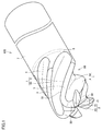
- FIG. 1 is a schematic perspective view showing the configuration of a cutting tool according to the first embodiment.
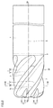
- FIG. 2 is a schematic side view showing the configuration of the cutting tool according to the first embodiment.
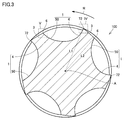
- FIG. 3 is a schematic cross-sectional view taken along the line III-III of FIG.
- FIG. 4 is an enlarged schematic view of region IV of FIG.
- FIG. 5 is an enlarged schematic view of the region V of FIG.
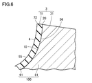
- FIG. 6 is a partial cross-sectional schematic diagram showing the configuration of the cutting tool according to the second embodiment.
- FIG. 7 is a partial cross-sectional schematic diagram showing the configuration of the cutting tool according to the third embodiment.
- FIG. 8 is a schematic first cross-sectional view showing the configuration of the cutting tool according to the fourth embodiment.
- FIG. 1 is a schematic perspective view showing the configuration of a cutting tool according to the first embodiment.
- FIG. 2 is a schematic side view showing the configuration of the cutting tool according to the first embodiment.
- FIG. 3 is a schematic cross-sectional view taken
- FIG. 9 is a schematic second sectional view showing the configuration of the cutting tool according to the fourth embodiment.
- FIG. 10 is a diagram showing the relationship between the angle formed by the two adjacent straight lines and the position in the first chip discharge groove.
- FIG. 11 is a partial cross-sectional schematic diagram showing the configuration of the cutting tool according to the fourth embodiment.
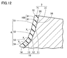
- FIG. 12 is a partial cross-sectional schematic diagram showing the configuration of the cutting tool according to the fifth embodiment.
- FIG. 13 is a partial cross-sectional schematic diagram showing the configuration of the cutting tool according to the sixth embodiment.
- FIG. 14 is a schematic cross-sectional view showing a state in which cutting is performed using the cutting tool according to the fourth embodiment.
- the cutting tool 100 includes a rake surface 4, a flank surface 3, a base material 81, and a first oxide film 91.
- the flank 3 is connected to the rake face 4.
- the base material 81 has a first surface 10 facing the rake surface 4.
- the first oxide film 91 has a second surface 56 in contact with the first surface 10 and a third surface 55 on the opposite side of the second surface 56.
- the ridgeline between the rake face 4 and the flank surface 3 constitutes the cutting edge 72.
- the third surface 55 constitutes at least a part of the rake surface 4.
- the first oxide film 91 may further include a fourth surface 71 connecting the second surface 56 and the third surface 55.
- the fourth surface 71 may form at least a part of the flank surface 3.
- the ridgeline between the third surface 55 and the fourth surface 71 may constitute the cutting edge 72.
- the first oxide film 91 may contain at least one of aluminum, titanium, chromium, zirconium, cobalt and tungsten.
- the cutting tool 100 according to (1) above may further include a second oxide film 92 that constitutes at least a part of the flank surface 3.
- the thickness of the second oxide film 92 may be smaller than the thickness of the first oxide film 91.
- the first oxide film 91 may be connected to the second oxide film 92.
- the first oxide film 91 may be separated from the second oxide film 92.
- the first oxide film 91 may contain at least one of aluminum, titanium, chromium, zirconium, cobalt and tungsten. ..
- the second oxide film 92 may contain at least one of aluminum, titanium, chromium, zirconium, cobalt and tungsten. ..
- the base material 81 may contain cubic boron nitride.
- the cutting tool may be a multi-blade rotary cutting tool.
- FIG. 1 is a schematic perspective view showing the configuration of the cutting tool 100 according to the first embodiment.
- FIG. 2 is a schematic side view showing the configuration of the cutting tool 100 according to the first embodiment.
- the cutting tool 100 according to the present embodiment is, for example, an end mill, which is composed of a blade portion 90, a joint portion 8, and a shank portion 7.
- the blade portion 90 has a first rake face 4, a first flank 3, a second rake face 15, a second flank 30, an outer peripheral cutting blade 72, a bottom cutting blade 21, and a front end 58. is doing.
- the shank portion 7 has a rear end 59.
- the blade portion 90 is fixed to the shank portion 7 by the joint portion 8.
- the joint portion 8 is a brazing material.
- the joint portion 8 is located between the blade portion 90 and the shank portion 7.
- the cutting tool 100 is configured to be rotatable around the axis A. From another point of view, the axis A is the axis of rotation of the cutting tool 100.
- the material constituting the blade portion 90 includes, for example, a cubic boron nitride (cBN) sintered body.
- the shank portion 7 contains, for example, a cemented carbide.
- the cemented carbide is, for example, a tungsten carbide (WC) -based cemented carbide, a cemented carbide containing Co in addition to WC, a cemented carbide to which carbonitrides such as Cr, Ti, Ta, and Nb are added in addition to WC. Is.
- the front end 58 of the cutting tool 100 is a portion facing the work material.
- the rear end 59 of the cutting tool 100 is a portion facing the tool that rotates the cutting tool 100.
- the shank portion 7 is a portion attached to a tool for rotating the cutting tool 100.
- the direction along the axis A is the axial direction.
- the direction perpendicular to the axial direction is the radial direction.
- the direction from the front end 58 to the rear end 59 is referred to as an axial rearward.
- the direction from the rear end 59 to the front end 58 is referred to as an axial front.
- the first flank surface 3 is connected to the first rake surface 4.
- the ridgeline between the first rake surface 4 and the first flank surface 3 constitutes the outer peripheral cutting edge 72.
- the second flank surface 30 is connected to the second rake surface 15.
- the ridgeline between the second rake surface 15 and the second flank surface 30 constitutes the bottom cutting blade 21.
- the first rake face 4 is connected to the second rake face 15.
- the first rake face 4 is located rearward in the axial direction with respect to the second rake face 15.
- the first flank 3 is connected to the second flank 30.
- the first flank 3 is located rearward in the axial direction with respect to the second flank 30.
- a first chip discharge groove 1 and a second chip discharge groove 2 are formed in the blade portion 90 of the cutting tool 100.
- the first chip discharge groove 1 is composed of a first rake surface 4 and a first chip discharge surface 50.
- the second chip discharge groove 2 is composed of a second rake surface 15 and a second chip discharge surface 45.
- the second chip discharge surface 45 is connected to the first chip discharge surface 50.
- the first chip discharge groove 1 is spirally provided around the axis A.
- the second chip discharge groove 2 is connected to the first chip discharge groove 1. In the direction along the axis A, the length of the first chip discharge groove 1 is longer than the length of the second chip discharge groove 2.
- the cutting tool 100 is, for example, a multi-blade rotary cutting tool.
- the number of outer peripheral cutting blades 72 is, for example, 2 or more.
- the lower limit of the number of outer peripheral cutting blades 72 is not particularly limited, but may be, for example, 4 or more, or 8 or more.
- the upper limit of the number of outer peripheral cutting blades 72 is not particularly limited, but may be, for example, 20 or less, or 16 or less.
- the number of outer peripheral cutting blades 72 is 5.
- the number of bottom cutting blades 21 may be the same as the number of outer peripheral cutting blades 72.
- FIG. 3 is a schematic cross-sectional view taken along the line III-III of FIG.
- the cross section shown in FIG. 3 is a cross section perpendicular to the axis.
- a plurality of first chip discharge grooves 1 are arranged in the circumferential direction (rotational direction R).
- a plurality of first flanks 3 are arranged in the circumferential direction.
- a plurality of outer peripheral cutting blades 72 are arranged in the circumferential direction. That is, assuming that the combination of the first flank 3, the first chip discharge groove 1, and the outer peripheral cutting edge 72 is one cutting component, a plurality of cutting components are arranged in the circumferential direction.
- the first chip discharge groove 1 is located forward in the rotation direction with respect to the first flank surface 3.
- the first rake face 4 is located forward in the rotational direction with respect to the outer peripheral cutting edge 72.
- the first chip discharge surface 50 is located forward in the rotation direction with respect to the first rake surface 4.
- first flank 3 and the first chip discharge groove 1 are alternately located.
- One end of the first flank 3 constitutes the outer peripheral cutting edge 72.
- the other end of the first flank 3 constitutes the tail portion 6.
- the first flank 3 is connected to the first rake face 4 on the outer peripheral cutting edge 72.
- the first flank 3 is connected to the first chip discharge surface 50 in the tail portion 6.
- first length L1 is longer than the length from the axis A to the tail portion 6 (second length L2).
- FIG. 4 is an enlarged schematic view of region IV of FIG.
- the blade portion 90 of the cutting tool 100 in a cross section perpendicular to the axis A, has a base material 81 and an oxide layer 80.
- the oxide layer 80 has, for example, a first oxide film 91 and a second oxide film 92.
- the base material 81 has a first surface 10.
- the first surface 10 faces the rake surface 4.
- the first oxide film 91 has a second surface 56 and a third surface 55.
- the second surface 56 is in contact with the first surface 10.
- the third surface 55 is on the opposite side of the second surface 56.
- the third surface 55 constitutes at least a part of the rake surface 4. In other words, the entire surface of the third surface 55 may be the rake surface 4, or a part of the third surface 55 may be the rake surface 4.
- the base material 81 has a fifth surface 31.
- the fifth surface 31 is connected to the first surface 10.
- the fifth surface 31 faces the escape surface 3.
- the boundary between the first surface 10 and the fifth surface 31 is the first ridge line 20.
- the second oxide film 92 constitutes at least a part of the flank 3.
- the second oxide film 92 has a sixth surface 57 in contact with the fifth surface 31 and a seventh surface 93 on the opposite side of the sixth surface 57.
- the seventh surface 93 constitutes at least a part of the escape surface 3. In other words, the entire surface of the seventh surface 93 may be the flank 3, or a part of the seventh surface 93 may be the flank 3.
- the first oxide film 91 may be connected to the second oxide film 92.
- the first oxide film 91 may be formed integrally with the second oxide film 92.
- the thickness of the second oxide film 92 may be smaller than the thickness of the first oxide film 91.
- the thickness of the first oxide film 91 (hereinafter, also referred to as the first thickness) is, for example, 5 ⁇ m or less.
- the first thickness is the thickness of the first oxide film 91 in the direction perpendicular to the tangent line of the first rake face 4.
- the first thickness may be, for example, 1 ⁇ m or less, or 0.1 ⁇ m or less.
- the lower limit of the first thickness is not particularly limited, but may be, for example, 0.01 ⁇ m or more.
- the thickness of the second oxide film 92 (hereinafter, also referred to as the second thickness) is, for example, 5 ⁇ m or less.
- the second thickness is the thickness of the second oxide film 92 in the direction perpendicular to the tangent line of the first flank surface 3.
- the second thickness may be, for example, 1 ⁇ m or less, or 0.1 ⁇ m or less.
- the lower limit of the second thickness is not particularly limited, but may be, for example, 0.01 ⁇ m or more.
- the measurement sample is cut in a cross section perpendicular to the axis.
- the measurement sample is embedded in the resin, and CP (Cross section polish) processing is performed on the cross section.
- the composition of each of the first oxide film 91 and the second oxide film 92 can be specified, for example, by using an energy dispersive X-ray analyzer (EDX) attached to a scanning electron microscope (SEM).
- EDX energy dispersive X-ray analyzer
- SEM scanning electron microscope
- JSM-7800F manufactured by JEOL Ltd.
- the EDX for example, an OctaneElect EDS system can be used.
- the measurement magnification can be, for example, 5000 times.
- the thickness of the first oxide film 91 is 0.1 ⁇ D1 from the outer peripheral cutting edge 72 toward the tail portion 6.
- the thickness of the second oxide film 92 is 0.5 ⁇ D2 from the outer peripheral cutting edge 72 toward the tail portion 6. It is the thickness of the second oxide film 92 at a position separated by a length (in other words, the center position of the first flank 3).
- FIG. 5 is an enlarged schematic view of the region V of FIG.
- the base material 81 has an eighth surface 40.
- the eighth surface 40 faces the first chip discharge surface 50.
- the eighth surface 40 is connected to each of the first surface 10 and the fifth surface 31. In the circumferential direction, the eighth surface 40 is located between the first surface 10 and the fifth surface 31.
- the boundary between the eighth surface 40 and the fifth surface 31 constitutes the second ridge line 5.
- the first oxide film 91 may be in contact with the eighth surface 40.
- the first oxide film 91 may be in contact with the second ridge line 5.
- the second oxide film 92 may be in contact with the second ridge line 5.
- the first oxide film 91 may be continuously provided from the first ridge line 20 to the second ridge line 5 in the first chip discharge groove 1.
- the second oxide film 92 may be continuously provided from the first ridge line 20 to the second ridge line 5 on the first flank surface 3.
- the base material 81 may contain, for example, cubic boron nitride (cBN). Specifically, the base material 81 may be composed of a cBN sintered body. The base material 81 may have, for example, cBN particles and a binder. The binder may contain at least one of aluminum (Al), titanium (Ti), chromium (Cr), zirconium (Zr), cobalt (Co) and tungsten (W). The base material 81 may contain diamond. The base material 81 may be single crystal diamond or polycrystalline diamond.
- the first oxide film 91 may contain at least one of aluminum, titanium, chromium, zirconium, cobalt and tungsten.
- the first oxide film 91 may be, for example, a coating film.
- the coating film may be formed by, for example, a CVD (Chemical Vapor Deposition) method or a PVD (Physical Vapor Deposition) method.
- the first oxide film 91 may be formed by irradiating the surface of the base material 81 with a laser to oxidize a part of the elements constituting the base material 81.
- the first oxide film 91 may be an oxide of a part of the elements constituting the base material 81.
- the first oxide film 91 may be an oxide of an element constituting a binder contained in the base material 81.
- the first oxide film 91 may contain, for example, Al 2 O 3 , TiO 2 , CoO, W 2 O 3 , and the like.
- the second oxide film 92 may contain at least one of aluminum, titanium, chromium, zirconium, cobalt and tungsten.
- the second oxide film 92 may be, for example, a coating film.
- the coating film may be formed by, for example, a CVD method or a PVD method.
- the second oxide film 92 may be formed by irradiating the surface of the base material 81 with a laser to oxidize a part of the elements constituting the base material 81.
- the second oxide film 92 may be an oxide of a part of the elements constituting the base material 81.
- the second oxide film 92 may be an oxide of an element constituting the binder contained in the base material 81.
- the second oxide film 92 may contain, for example, Al 2 O 3 , TiO 2 , CoO, W 2 O 3 , and the like.
- the cutting tool 100 according to the second embodiment is different from the cutting tool 100 according to the first embodiment in the configuration not having the second oxide film 92, and the cutting tool 100 according to the first embodiment is different from the cutting tool 100 according to the first embodiment. It is the same as 100.
- a configuration different from that of the cutting tool 100 according to the first embodiment will be mainly described.
- FIG. 6 is a partial cross-sectional schematic diagram showing the configuration of the cutting tool 100 according to the second embodiment.
- the region shown in FIG. 6 corresponds to region IV in FIG.
- the first oxide film 91 may include a fourth surface 71 connecting the second surface 56 and the third surface 55.
- the fourth surface 71 of the first oxide film 91 is provided along the fifth surface 31 of the base material 81.
- the ridgeline between the third surface 55 and the fourth surface 71 constitutes the outer peripheral cutting edge 72.
- No oxide film is provided on the fifth surface 31.
- the fifth surface 31 of the base material 81 is exposed from the first oxide film 91.
- the fourth surface 71 constitutes at least a part of the first flank surface 3.
- the first flank 3 may include a fourth surface 71 and a fifth surface 31.
- the cutting tool 100 according to the third embodiment is different from the cutting tool 100 according to the first embodiment in the configuration in which the first oxide film 91 is separated from the second oxide film 92, and in other configurations, the cutting tool 100 is the first. This is the same as the cutting tool 100 according to the embodiment.
- a configuration different from that of the cutting tool 100 according to the first embodiment will be mainly described.
- FIG. 7 is a partial cross-sectional schematic diagram showing the configuration of the cutting tool 100 according to the third embodiment.
- the region shown in FIG. 7 corresponds to region IV in FIG.
- the first oxide film 91 may be separated from the second oxide film 92.
- a part of the first surface 10 is exposed from the first oxide film 91.
- the first surface 10 has a first region 18 in contact with the first oxide film 91 and a second region 17 connected to the first region 18 and separated from the first oxide film 91.
- the third surface 55 and the second region 17 form a rake surface 4.
- the fifth surface 31 is exposed from the second oxide film 92.
- the fifth surface 31 has a third region 33 in contact with the second oxide film 92 and a fourth region 34 connected to the third region 33 and separated from the second oxide film 92.
- the seventh surface 93 and the fourth region 34 form a flank 3.
- the ridgeline between the second region 17 and the fourth region 34 constitutes the outer peripheral cutting edge 72.
- the second oxide film 92 may have a portion whose thickness increases as the distance from the outer peripheral cutting edge 72 increases.
- the cutting tool 100 according to the fourth embodiment is different from the cutting tool 100 according to the first embodiment in that the first surface 10 of the base material 81 is composed of a plurality of straight portions, and in other configurations, the first embodiment is used. This is the same as the cutting tool 100 according to the above.
- a configuration different from that of the cutting tool 100 according to the first embodiment will be mainly described.
- FIG. 8 is a schematic first cross-sectional view showing the configuration of the cutting tool 100 according to the fourth embodiment.
- the region shown in FIG. 8 corresponds to region IV in FIG. In FIG. 8, only the base material 81 is shown, and the oxide film is not shown.
- the first surface 10 is composed of a plurality of straight lines.
- the plurality of straight line portions include, for example, a first straight line portion 11, a second straight line portion 12, a third straight line portion 13, and a fourth straight line portion 14.
- the first straight line portion 11 is connected to the first flank surface 3.
- the first straight line portion 11 is inclined with respect to the fifth surface 31.
- the boundary between the first straight line portion 11 and the fifth surface 31 is the first ridge line 20.
- the second straight line portion 12 is inclined with respect to the first straight line portion 11.
- the second straight line portion 12 is connected to the first straight line portion 11.
- the second straight line portion 12 is located on the side opposite to the fifth surface 31 with respect to the first straight line portion 11. From another point of view, the first straight line portion 11 is located between the second straight line portion 12 and the fifth surface 31.
- the third straight line portion 13 is inclined with respect to the second straight line portion 12.
- the third straight line portion 13 is connected to the second straight line portion 12.
- the third straight line portion 13 is located on the side opposite to the first straight line portion 11 with respect to the second straight line portion 12.
- the second straight line portion 12 is located between the third straight line portion 13 and the first straight line portion 11.
- the fourth straight line portion 14 is inclined with respect to the third straight line portion 13.
- the fourth straight line portion 14 is connected to the third straight line portion 13.
- the fourth straight line portion 14 is located on the opposite side of the second straight line portion 12 with respect to the third straight line portion 13. From another point of view, the third straight line portion 13 is located between the fourth straight line portion 14 and the second straight line portion 12.
- the angle formed by two adjacent straight portions among the plurality of straight portions may become smaller as the distance from the fifth surface 31 increases.
- the first angle ⁇ 1 formed by the first straight line portion 11 and the second straight line portion 12 is from the second angle ⁇ 2 formed by the second straight line portion 12 and the third straight line portion 13. May be large.
- the second angle ⁇ 2 formed by the second straight line portion 12 and the third straight line portion 13 may be larger than the third angle ⁇ 3 formed by the third straight line portion 13 and the fourth straight line portion 14. ..
- the first angle ⁇ 1 is, for example, 140 ° or more and less than 180 °.
- the lower limit of the first angle ⁇ 1 is not particularly limited, but may be, for example, 150 ° or more, or 160 ° or more.
- the upper limit of the first angle ⁇ 1 is not particularly limited, but may be, for example, 178 ° or less, or 175 ° or less.
- a first linear portion 11 a boundary between the second straight portion 12 is a first position X 1.
- the boundary between the second straight line portion 12 and the third straight line portion 13 is the second position X 2 .
- a third straight portion 13 boundary between the fourth straight portion 14 is a third position X 3.
- the length of the first straight line portion 11 (straight line distance between the outer peripheral cutting edge 72 and the first position X 1 ) is the length of the second straight line portion 12 (straight line distance between the first position X 1 and the second position X 2). ) May be larger.
- the length of the second straight line portion 12 (the straight line distance between the first position X 1 and the second position X 2 ) is the length of the third straight line portion 13 (the straight line between the second position X 2 and the third position X 3). It may be larger than the distance).
- the distance between the outer peripheral cutting edge 72 and the first position X 1 (first distance a1) is the same as the distance between the first position X 1 and the second position X 2 (second distance a2). May be good.
- the distance between the first position X 1 and the second position X 2 (second distance a2) is the same as the distance between the second position X 2 and the third position X 3 (third distance a3). You may.
- FIG. 9 is a schematic second sectional view showing the configuration of the cutting tool 100 according to the fourth embodiment.
- the region shown in FIG. 9 corresponds to the region V in FIG. In FIG. 9, only the base material 81 is shown, and the oxide film is not shown.
- the eighth surface 40 may be composed of, for example, a plurality of straight lines.
- the eighth surface 40 has, for example, a fifth straight line portion 41, a sixth straight line portion 42, a seventh straight line portion 43, and an eighth straight line portion 44.
- the fifth straight line portion 41 is inclined with respect to the fifth surface 31.
- the fifth straight line portion 41 is connected to the second ridge line 5.
- the sixth straight line portion 42 is inclined with respect to the fifth straight line portion 41.
- the sixth straight line portion 42 is connected to the fifth straight line portion 41.
- the sixth straight line portion 42 is located on the side opposite to the second ridge line 5 with respect to the fifth straight line portion 41. From another point of view, the fifth straight line portion 41 is located between the sixth straight line portion 42 and the second ridge line 5.
- the 7th straight line portion 43 is inclined with respect to the 6th straight line portion 42.
- the seventh straight line portion 43 is connected to the sixth straight line portion 42.
- the seventh straight line portion 43 is located on the opposite side of the sixth straight line portion 42 from the fifth straight line portion 41.
- the sixth straight line portion 42 is located between the seventh straight line portion 43 and the fifth straight line portion 41.
- the eighth straight line portion 44 is inclined with respect to the seventh straight line portion 43.
- the eighth straight line portion 44 is connected to the seventh straight line portion 43.
- the eighth straight line portion 44 is located on the opposite side of the seventh straight line portion 43 from the sixth straight line portion 42. From another point of view, the seventh straight line portion 43 is located between the eighth straight line portion 44 and the sixth straight line portion 42.
- the fourth angle ⁇ n-1 formed by the fifth straight line portion 41 and the sixth straight line portion 42 is larger than the fifth angle ⁇ n-2 formed by the sixth straight line portion 42 and the seventh straight line portion 43. It may be large.
- the fifth angle ⁇ n-2 formed by the sixth straight line portion 42 and the seventh straight line portion 43 is larger than the sixth angle ⁇ n-3 formed by the seventh straight line portion 43 and the eighth straight line portion 44. It may be large.
- the boundary between the fifth straight line portion 41 and the sixth straight line portion 42 is the fourth position X n-1 .
- the boundary between the sixth straight line portion 42 and the seventh straight line portion 43 is the fifth position X n-2 .
- the boundary between the 7th straight line portion 43 and the 8th straight line portion 44 is the 6th position Xn-3 .
- the length of the fifth straight line portion 41 (the straight line distance between the second ridge line 5 and the fourth position X n-1 ) is the length of the sixth straight line portion 42 (the fourth position X n-1 and the fifth position X n-1). It may be larger than the linear distance from -2).
- the length of the sixth straight line portion 42 ( straight line distance between the fourth position X n-1 and the fifth position X n-2 ) is the length of the seventh straight line portion 43 (fifth position X n-2 and the sixth position). It may be larger than the linear distance from the position X n-3).
- the distance between the second ridge line 5 and the fourth position X n-1 (fourth distance b1) is the distance between the fourth position X n-1 and the fifth position X n-2 (fifth distance b2). ) May be the same.
- the distance between the 4th position X n-1 and the 5th position X n-2 (fifth distance b2) is the distance between the 5th position X n-2 and the 6th position X n-3 (the first). It may be the same as 6 distance b3).
- FIG. 10 is a diagram showing the relationship between the angle formed by two adjacent straight lines and the position in the circumferential direction.
- the angle formed by the two adjacent straight lines may monotonically decrease from the first ridge line 20 to the eighth surface 40.
- the first surface 10 may be composed of, for example, five or more straight lines.
- the eighth surface 40 may monotonically decrease from the second ridge line 5 toward the first surface 10.
- the eighth surface 40 may be composed of, for example, five or more straight lines.
- the surface of the base material 81 facing the first chip discharge groove 1 may be composed of a plurality of straight lines.
- the lower limit of the number of straight lines is not particularly limited, but may be, for example, 10 or more, or 20 or more.
- the upper limit of the number of straight portions is not particularly limited, but may be, for example, 50 or less, or 40 or less.
- B) is, for example, 8 ° or more.
- the lower limit of the angle difference B is not particularly limited, but may be, for example, 10 ° or more, or 12 ° or more.
- the upper limit of the angle difference B is not particularly limited, but may be, for example, 30 ° or less.
- FIG. 11 is a partial cross-sectional schematic diagram showing the configuration of the cutting tool 100 according to the fourth embodiment.
- the region shown in FIG. 11 corresponds to region IV in FIG.
- the cutting tool 100 has a base material 81, a first oxide film 91, and a second oxide film 92. ..
- the first surface 10 faces the rake surface 4.
- the first oxide film 91 has a second surface 56 and a third surface 55.
- the second surface 56 is in contact with the first surface 10.
- the third surface 55 is on the opposite side of the second surface 56.
- the third surface 55 is a rake surface 4.
- the base material 81 has a fifth surface 31.
- the fifth surface 31 is connected to the first surface 10.
- the fifth surface 31 faces the escape surface 3.
- the second oxide film 92 constitutes the flank 3.
- the second oxide film 92 has a sixth surface 57 in contact with the fifth surface 31 and a seventh surface 93 on the opposite side of the sixth surface 57.
- the seventh surface 93 is the escape surface 3.
- the rake face 4 may be composed of a plurality of straight lines.
- the rake face 4 may have a ninth straight line portion 51, a tenth straight line portion 52, an eleventh straight line portion 53, and a twelfth straight line portion 54.
- the ninth straight line portion 51 faces the first straight line portion 11.
- the tenth straight line portion 52 faces the second straight line portion 12.
- the eleventh straight line portion 53 faces the third straight line portion 13.
- the twelfth straight line portion 54 faces the fourth straight line portion 14.
- the ninth straight line portion 51 is connected to the first flank surface 3.
- the ninth straight line portion 51 is inclined with respect to the first flank surface 3.
- the boundary between the ninth straight line portion 51 and the first flank 3 is the outer peripheral cutting edge 72.
- the tenth straight line portion 52 is inclined with respect to the ninth straight line portion 51.
- the tenth straight line portion 52 is connected to the ninth straight line portion 51.
- the tenth straight line portion 52 is located on the side opposite to the first flank 3 with respect to the ninth straight line portion 51. From another point of view, the ninth straight line portion 51 is located between the tenth straight line portion 52 and the first flank surface 3.
- the 11th straight line portion 53 is inclined with respect to the 10th straight line portion 52.
- the eleventh straight line portion 53 is connected to the tenth straight line portion 52.
- the eleventh straight line portion 53 is located on the opposite side of the tenth straight line portion 52 from the ninth straight line portion 51. From another point of view, the tenth straight line portion 52 is located between the eleventh straight line portion 53 and the ninth straight line portion 51.
- the twelfth straight line portion 54 is inclined with respect to the eleventh straight line portion 53.
- the twelfth straight line portion 54 is connected to the eleventh straight line portion 53.
- the twelfth straight line portion 54 is located on the opposite side of the tenth straight line portion 52 with respect to the eleventh straight line portion 53. From another point of view, the eleventh straight line portion 53 is located between the twelfth straight line portion 54 and the tenth straight line portion 52.
- the cutting tool 100 according to the fifth embodiment is different from the cutting tool 100 according to the fourth embodiment in the configuration not having the second oxide film 92, and the cutting tool 100 according to the fourth embodiment is different from the cutting tool 100 according to the fourth embodiment. It is the same as 100.
- a configuration different from that of the cutting tool 100 according to the fourth embodiment will be mainly described.
- FIG. 12 is a partial cross-sectional schematic diagram showing the configuration of the cutting tool 100 according to the fifth embodiment.
- the region shown in FIG. 12 corresponds to region IV in FIG.
- the first oxide film 91 may further include a fourth surface 71 connecting the second surface 56 and the third surface 55.
- the fourth surface 71 of the first oxide film 91 is provided along the fifth surface 31 of the base material 81.
- the ridgeline between the third surface 55 and the fourth surface 71 constitutes the outer peripheral cutting edge 72.
- No oxide film is provided on the fifth surface 31.
- the fifth surface 31 of the base material 81 is exposed from the first oxide film 91.
- the fourth surface 71 constitutes at least a part of the first flank surface 3.
- the first flank 3 may include a fourth surface 71 and a fifth surface 31.
- the cutting tool 100 according to the sixth embodiment is different from the cutting tool 100 according to the fourth embodiment in the configuration in which the first oxide film 91 is separated from the second oxide film 92, and in the other configurations, the fourth This is the same as the cutting tool 100 according to the embodiment.
- a configuration different from that of the cutting tool 100 according to the fourth embodiment will be mainly described.
- FIG. 13 is a partial cross-sectional schematic diagram showing the configuration of the cutting tool 100 according to the sixth embodiment.
- the region shown in FIG. 13 corresponds to region IV in FIG.
- the first oxide film 91 may be separated from the second oxide film 92.
- a part of the first surface 10 is exposed from the first oxide film 91.
- the first surface 10 has a first region 18 in contact with the first oxide film 91 and a second region 17 connected to the first region 18 and separated from the first oxide film 91.
- the third surface 55 and the second region 17 form a rake surface 4.
- the second region 17 may be a part of the first straight line portion 11.
- the fifth surface 31 is exposed from the second oxide film 92.
- the fifth surface 31 has a third region 33 in contact with the second oxide film 92 and a fourth region 34 connected to the third region 33 and separated from the second oxide film 92.
- the second oxide film 92 has a sixth surface 57 in contact with the fifth surface 31 and a seventh surface 93 on the opposite side of the sixth surface 57.
- the seventh surface 93 and the fourth region 34 form a flank 3.
- the ridgeline between the second region 17 and the fourth region 34 constitutes the outer peripheral cutting edge 72.
- the second oxide film 92 may have a portion whose thickness increases as the distance from the outer peripheral cutting edge 72 increases.
- the cutting tool 100 is, for example, a rotary cutting tool, and more specifically, a multi-blade rotary cutting tool.
- the cutting tool 100 is, for example, an end mill, but is not limited to the end mill.
- the cutting tool 100 may be, for example, a reamer, a drill, or a tap.
- the cutting tool 100 may be, for example, a turning tool.
- the cutting tool 100 may be a throw-away insert.
- FIG. 14 is a schematic cross-sectional view showing a state in which cutting is performed using the cutting tool 100 according to the fourth embodiment.
- the chips 61 of the work material 60 cut by the cutting edge 72 of the cutting tool 100 are discharged while being in contact with the rake face 4.
- the chip 61 may be welded to the rake surface 4.
- the cutting edge 72 may be broken due to the welding of the chips 61.
- the cutting tool 100 has a first oxide film 91.
- the first oxide film 91 has a second surface 56 in contact with the first surface 10 and a third surface 55 on the opposite side of the second surface 56.
- the third surface 55 constitutes at least a part of the rake surface 4. That is, at least a part of the rake face 4 is composed of the first oxide film 91.
- the first surface 10 of the base material 81 may be composed of a plurality of straight lines in a cross section perpendicular to the axis A.
- the first surface 10 includes the first straight line portion 11 and the second straight line portion 12 that is inclined with respect to the first straight line portion 11 and is connected to the first straight line portion 11.
- a third straight line portion 13 that is inclined with respect to the second straight line portion 12 and is connected to the second straight line portion 12 may be provided.
- the chips 61 move on the rake face 4
- the chips 61 are curled with a certain curvature.
- a gap 9 is formed between the curled chip 61, the boundary between the ninth straight line portion 51 facing the first straight line portion 11, and the tenth straight line portion 52 facing the second straight line portion 12.
- a gap 9 is formed between the curled chip 61, the boundary between the tenth straight line portion 52 facing the second straight line portion 12, and the eleventh straight line portion 53 facing the third straight line portion 13. Will be done.
- the coolant is drawn into the gap 9 by the capillary phenomenon. This allows the coolant to be effectively transported and retained near the cutting point. As a result, the frictional force between the chips 61 and the rake face 4 can be reduced. Therefore, it is possible to prevent the cutting edge 72 from breaking.
- the cutting tools 100 of the samples 1 to 9 were prepared.
- the cutting tool 100 of the samples 1 to 8 is an end mill according to an embodiment.
- the cutting tool 100 of the sample 9 is an end mill according to a comparative example.
- the base material 81 is brazed to the tip of the shank portion made of cemented carbide.
- the base material 81 is made of a cBN sintered body.
- an oxide film is formed on the base material 81.
- no oxide film is formed on the base material 81.
- the thickness of the first oxide film 91 constituting the first rake face 4 was set to 5 ⁇ m.
- the thickness of the second oxide film 92 constituting the first flank 3 was set to 8 ⁇ m.
- the first oxide film 91 and the second oxide film 92 were coated on the substrate 81 using PVD (see FIG. 11).
- Each of the first oxide film 91 and the second oxide film 92 has a laminated structure of Al 2 O 3 and TiO 2.
- the thickness of the first oxide film 91 constituting the first rake face 4 was set to 5 ⁇ m.
- the thickness of the second oxide film 92 constituting the first flank 3 was set to 8 ⁇ m.
- the first oxide film 91 and the second oxide film 92 were coated on the substrate 81 using PVD (see FIG. 11).
- Each of the first oxide film 91 and the second oxide film 92 has a laminated structure of Al 2 O 3 and TiO 2. After coating the second oxide film 92, the first flank surface 3 was surface-treated to reduce the thickness of the second oxide film 92.
- the thickness of the first oxide film 91 constituting the first rake face 4 was set to 5 ⁇ m.
- the thickness of the second oxide film 92 constituting the first flank 3 was set to 1 ⁇ m.
- the first oxide film 91 and the second oxide film 92 were coated on the base material 81 using PVD.
- Each of the first oxide film 91 and the second oxide film 92 has a laminated structure of Al 2 O 3 and TiO 2.
- the first flank surface 3 was surface-treated to reduce the thickness of the second oxide film 92 (see FIG. 11).
- the thickness of the first oxide film 91 constituting the first rake face 4 was set to 5 ⁇ m.
- the thickness of the second oxide film 92 constituting the first flank 3 was set to 0 ⁇ m.
- the first oxide film 91 was coated on the substrate 81 using PVD.
- the first oxide film 91 has a laminated structure of Al 2 O 3 and TiO 2.
- the second oxide film 92 was removed by surface-treating the first flank 3 after coating the second oxide film 92.
- the first flank 3 is made of a base material 81 (see FIG. 12).
- the thickness of the first oxide film 91 constituting the first rake face 4 was set to 2 ⁇ m.
- the thickness of the second oxide film 92 constituting the first flank 3 was set to 1 ⁇ m.
- the first oxide film 91 and the second oxide film 92 were formed by surface-treating the base material 81 with a laser to oxidize the elements contained in the base material 81 (see FIG. 11).
- Each of the first oxide film 91 and the second oxide film 92 contains Al 2 O 3 and TiO 2.
- the thickness of the first oxide film 91 constituting the first rake face 4 was set to 2 ⁇ m.
- the thickness of the second oxide film 92 constituting the first flank 3 was set to 0.5 ⁇ m.
- the first oxide film 91 and the second oxide film 92 were formed by surface-treating the base material 81 with a laser to oxidize the elements contained in the base material 81 (see FIG. 11).
- Each of the first oxide film 91 and the second oxide film 92 contains Al 2 O 3 , TiO 2 and CoO.
- the thickness of the first oxide film 91 constituting the first rake face 4 was set to 2 ⁇ m.
- the thickness of the second oxide film 92 constituting the first flank 3 was set to 0 ⁇ m.
- the first oxide film 91 was formed by surface-treating the base material 81 with a laser to oxidize the elements contained in the base material 81 (see FIG. 12).
- the first oxide film 91 contains Al 2 O 3 and TiO 2 and CoO.
- the thickness of the first oxide film 91 constituting the first rake face 4 was set to 2 ⁇ m.
- the thickness of the second oxide film 92 constituting the first flank 3 was set to 0 ⁇ m.
- the first oxide film 91 was formed by surface-treating the base material 81 with a laser to oxidize the elements contained in the base material 81 (see FIG. 12).
- the first oxide film 91 contains TiO 2 , CoO, and W 2 O 3 .
- the work material 60 was machined using the cutting tools 100 of the samples 1 to 9 (see FIG. 14).
- the work material 60 was Ti-6Al-4V.
- the cutting speed (Vc) was set to 500 mm / min.
- the feed amount (f) was 0.015 mm / blade.
- the depth of cut (Ae) in the lateral direction was 0.05 mm.
- the depth of cut (Ap) in the axial direction was 0.5 mm.
- the coolant was a 20-fold diluted emulsion.
- Table 1 shows the tool life when the work material 60 is machined using the cutting tools 100 of the samples 1 to 9.
- the tool life is the time from the start of machining to the loss of the cutting edge 72.
- the tool life when the work material 60 was machined using the cutting tools 100 of the samples 1 to 8 was 18 minutes or more and 38 minutes or less.
- the tool life was 9 minutes. From the above results, it was demonstrated that the chipping of the cutting edge 72 can be suppressed by forming the rake face 4 with the first oxide film 91 in the cross section perpendicular to the axis A.
Abstract
A cutting tool according to the present disclosure comprises a rake face, a flank face, a substrate, and a first oxide film. The flank face is continuous with the rake face. The substrate has a first face opposing the rake face. The first oxide film has a second face in contact with the first face, and a third face on the opposite side to the second face. A ridgeline between the rake face and the flank face forms a cutting edge. The third face forms at least a part of the rake face.
Description
本開示は、切削工具に関する。
This disclosure relates to cutting tools.
特開2017-159380号公報(特許文献1)には、すくい面に複数の筋目(凹部)が形成されたエンドミルが記載されている。
Japanese Unexamined Patent Publication No. 2017-159380 (Patent Document 1) describes an end mill in which a plurality of lines (recesses) are formed on a rake face.
本開示に係る切削工具は、すくい面と、逃げ面と、基材と、第1酸化膜とを備えている。逃げ面は、すくい面に連なっている。基材は、すくい面に対向する第1面を有している。第1酸化膜は、第1面に接する第2面と、第2面の反対側にある第3面とを有している。すくい面と逃げ面との稜線は、切刃を構成している。第3面は、すくい面の少なくとも一部を構成している。
The cutting tool according to the present disclosure includes a rake surface, a flank surface, a base material, and a first oxide film. The flank is connected to the rake face. The base material has a first surface facing the rake surface. The first oxide film has a second surface in contact with the first surface and a third surface on the opposite side of the second surface. The ridgeline between the rake face and the flank surface constitutes the cutting edge. The third surface constitutes at least a part of the rake surface.
[本開示が解決しようとする課題]
回転切削工具を用いて被削材を切削する場合には、クーラントに遠心力が作用するため、切削点近傍へクーラントを効果的に輸送しつつ、切削点近傍でクーラントを保持することが困難である。特開2017-159380号公報に記載のエンドミルにおいては、すくい面に設けられた凹部の谷の部分にクーラントが保持されることで、潤滑性を向上している。しかしながら、当該エンドミルにおいては、大きな切削抵抗が切刃にかかった場合に、凹部に応力が集中し、切刃が折損する場合があった。 [Issues to be resolved by this disclosure]
When cutting a work material using a rotary cutting tool, centrifugal force acts on the coolant, so it is difficult to hold the coolant near the cutting point while effectively transporting the coolant to the vicinity of the cutting point. be. In the end mill described in JP-A-2017-159380, the coolant is held in the valley portion of the recess provided on the rake surface to improve the lubricity. However, in the end mill, when a large cutting resistance is applied to the cutting edge, stress is concentrated on the concave portion and the cutting edge may be broken.
[本開示の効果]
本開示によれば、切刃が折損することを抑制可能な切削工具を提供することができる。 [Effect of this disclosure]
According to the present disclosure, it is possible to provide a cutting tool capable of suppressing the cutting edge from breaking.
本開示によれば、切刃が折損することを抑制可能な切削工具を提供することができる。 [Effect of this disclosure]
According to the present disclosure, it is possible to provide a cutting tool capable of suppressing the cutting edge from breaking.
[本開示の実施形態の概要]
まず、本開示の実施形態の概要について説明する。 [Summary of Embodiments of the present disclosure]
First, the outline of the embodiment of the present disclosure will be described.
まず、本開示の実施形態の概要について説明する。 [Summary of Embodiments of the present disclosure]
First, the outline of the embodiment of the present disclosure will be described.
(1)本開示に係る切削工具100は、すくい面4と、逃げ面3と、基材81と、第1酸化膜91とを備えている。逃げ面3は、すくい面4に連なっている。基材81は、すくい面4に対向する第1面10を有している。第1酸化膜91は、第1面10に接する第2面56と、第2面56の反対側にある第3面55とを有している。すくい面4と逃げ面3との稜線は、切刃72を構成している。第3面55は、すくい面4の少なくとも一部を構成している。
(1) The cutting tool 100 according to the present disclosure includes a rake surface 4, a flank surface 3, a base material 81, and a first oxide film 91. The flank 3 is connected to the rake face 4. The base material 81 has a first surface 10 facing the rake surface 4. The first oxide film 91 has a second surface 56 in contact with the first surface 10 and a third surface 55 on the opposite side of the second surface 56. The ridgeline between the rake face 4 and the flank surface 3 constitutes the cutting edge 72. The third surface 55 constitutes at least a part of the rake surface 4.
(2)上記(1)に係る切削工具100においては、第1酸化膜91は、第2面56と第3面55とを繋ぐ第4面71をさらに含んでいてもよい。第4面71は、逃げ面3の少なくとも一部を構成していてもよい。第3面55と第4面71との稜線は、切刃72を構成していてもよい。
(2) In the cutting tool 100 according to (1) above, the first oxide film 91 may further include a fourth surface 71 connecting the second surface 56 and the third surface 55. The fourth surface 71 may form at least a part of the flank surface 3. The ridgeline between the third surface 55 and the fourth surface 71 may constitute the cutting edge 72.
(3)上記(1)または(2)に係る切削工具100においては、第1酸化膜91は、アルミニウム、チタン、クロム、ジルコニウム、コバルトおよびタングステンの少なくともいずれかを含んでいてもよい。
(3) In the cutting tool 100 according to (1) or (2) above, the first oxide film 91 may contain at least one of aluminum, titanium, chromium, zirconium, cobalt and tungsten.
(4)上記(1)に係る切削工具100においては、逃げ面3の少なくとも一部を構成する第2酸化膜92をさらに備えていてもよい。第2酸化膜92の厚みは、第1酸化膜91の厚みよりも小さくてもよい。
(4) The cutting tool 100 according to (1) above may further include a second oxide film 92 that constitutes at least a part of the flank surface 3. The thickness of the second oxide film 92 may be smaller than the thickness of the first oxide film 91.
(5)上記(4)に係る切削工具100においては、第1酸化膜91は、第2酸化膜92に連なっていてもよい。
(5) In the cutting tool 100 according to (4) above, the first oxide film 91 may be connected to the second oxide film 92.
(6)上記(4)に係る切削工具100においては、第1酸化膜91は、第2酸化膜92から離間していてもよい。
(6) In the cutting tool 100 according to (4) above, the first oxide film 91 may be separated from the second oxide film 92.
(7)上記(4)から(6)のいずれかに係る切削工具100においては、第1酸化膜91は、アルミニウム、チタン、クロム、ジルコニウム、コバルトおよびタングステンの少なくともいずれかを含んでいてもよい。
(7) In the cutting tool 100 according to any one of (4) to (6) above, the first oxide film 91 may contain at least one of aluminum, titanium, chromium, zirconium, cobalt and tungsten. ..
(8)上記(4)から(7)のいずれかに係る切削工具100においては、第2酸化膜92は、アルミニウム、チタン、クロム、ジルコニウム、コバルトおよびタングステンの少なくともいずれかを含んでいてもよい。
(8) In the cutting tool 100 according to any one of (4) to (7) above, the second oxide film 92 may contain at least one of aluminum, titanium, chromium, zirconium, cobalt and tungsten. ..
(9)上記(1)から(8)のいずれかに係る切削工具100においては、基材81は、立方晶窒化硼素を含んでいてもよい。
(9) In the cutting tool 100 according to any one of (1) to (8) above, the base material 81 may contain cubic boron nitride.
(10)上記(1)から(9)のいずれかに係る切削工具100においては、切削工具は、多刃回転切削工具であってもよい。
(10) In the cutting tool 100 according to any one of (1) to (9) above, the cutting tool may be a multi-blade rotary cutting tool.
[本開示の実施形態の詳細]
以下、図面に基づいて本開示の実施形態(以降、本実施形態とも称する)の詳細について説明する。なお、以下の図面において同一または相当する部分には同一の参照番号を付し、その説明は繰返さない。 [Details of Embodiments of the present disclosure]
Hereinafter, the details of the embodiment of the present disclosure (hereinafter, also referred to as the present embodiment) will be described with reference to the drawings. In the following drawings, the same or corresponding parts will be given the same reference number, and the explanation will not be repeated.
(第1実施形態)
図1は、第1実施形態に係る切削工具100の構成を示す斜視模式図である。図2は、第1実施形態に係る切削工具100の構成を示す側面模式図である。図1および図2に示されるように、本実施形態に係る切削工具100は、たとえばエンドミルであって、刃部90と、接合部8と、シャンク部7とから構成されている。刃部90は、第1すくい面4と、第1逃げ面3と、第2すくい面15と、第2逃げ面30と、外周切刃72と、底切刃21と、前端58とを有している。シャンク部7は、後端59を有している。刃部90は、接合部8によってシャンク部7に固定されている。接合部8は、ロウ材である。接合部8は、刃部90とシャンク部7との間に位置している。 (First Embodiment)
FIG. 1 is a schematic perspective view showing the configuration of thecutting tool 100 according to the first embodiment. FIG. 2 is a schematic side view showing the configuration of the cutting tool 100 according to the first embodiment. As shown in FIGS. 1 and 2, the cutting tool 100 according to the present embodiment is, for example, an end mill, which is composed of a blade portion 90, a joint portion 8, and a shank portion 7. The blade portion 90 has a first rake face 4, a first flank 3, a second rake face 15, a second flank 30, an outer peripheral cutting blade 72, a bottom cutting blade 21, and a front end 58. is doing. The shank portion 7 has a rear end 59. The blade portion 90 is fixed to the shank portion 7 by the joint portion 8. The joint portion 8 is a brazing material. The joint portion 8 is located between the blade portion 90 and the shank portion 7.
図1は、第1実施形態に係る切削工具100の構成を示す斜視模式図である。図2は、第1実施形態に係る切削工具100の構成を示す側面模式図である。図1および図2に示されるように、本実施形態に係る切削工具100は、たとえばエンドミルであって、刃部90と、接合部8と、シャンク部7とから構成されている。刃部90は、第1すくい面4と、第1逃げ面3と、第2すくい面15と、第2逃げ面30と、外周切刃72と、底切刃21と、前端58とを有している。シャンク部7は、後端59を有している。刃部90は、接合部8によってシャンク部7に固定されている。接合部8は、ロウ材である。接合部8は、刃部90とシャンク部7との間に位置している。 (First Embodiment)
FIG. 1 is a schematic perspective view showing the configuration of the
切削工具100は、軸線Aの周りを回転可能に構成されている。別の観点から言えば、軸線Aは、切削工具100の回転軸である。刃部90を構成する材料は、たとえば立方晶窒化硼素(cBN)焼結体を含んでいる。シャンク部7は、たとえば超硬合金を含んでいる。超硬合金は、たとえば炭化タングステン(WC)基超硬合金、WCの他にCoを含む超硬合金、WCの他にCr、Ti、Ta、Nb等の炭窒化物を添加した超硬合金等である。
The cutting tool 100 is configured to be rotatable around the axis A. From another point of view, the axis A is the axis of rotation of the cutting tool 100. The material constituting the blade portion 90 includes, for example, a cubic boron nitride (cBN) sintered body. The shank portion 7 contains, for example, a cemented carbide. The cemented carbide is, for example, a tungsten carbide (WC) -based cemented carbide, a cemented carbide containing Co in addition to WC, a cemented carbide to which carbonitrides such as Cr, Ti, Ta, and Nb are added in addition to WC. Is.
切削工具100の前端58は、被削材に対向する部分である。切削工具100の後端59は、切削工具100を回転させる工具に対向する部分である。シャンク部7は、切削工具100を回転させる工具に取り付けられる部分である。軸線Aに沿った方向は、軸方向である。軸方向に対して垂直な方向が径方向である。本明細書においては、前端58から後端59に向かう方向を軸方向の後方と称する。反対に、後端59から前端58に向かう方向を軸方向の前方と称する。
The front end 58 of the cutting tool 100 is a portion facing the work material. The rear end 59 of the cutting tool 100 is a portion facing the tool that rotates the cutting tool 100. The shank portion 7 is a portion attached to a tool for rotating the cutting tool 100. The direction along the axis A is the axial direction. The direction perpendicular to the axial direction is the radial direction. In the present specification, the direction from the front end 58 to the rear end 59 is referred to as an axial rearward. On the contrary, the direction from the rear end 59 to the front end 58 is referred to as an axial front.
図1および図2に示されるように、第1逃げ面3は、第1すくい面4に連なる。第1すくい面4と第1逃げ面3との稜線は、外周切刃72を構成する。第2逃げ面30は、第2すくい面15に連なる。第2すくい面15と第2逃げ面30との稜線は、底切刃21を構成する。第1すくい面4は、第2すくい面15に連なっている。第1すくい面4は、第2すくい面15に対して、軸方向の後方に位置している。第1逃げ面3は、第2逃げ面30に連なっている。第1逃げ面3は、第2逃げ面30に対して、軸方向の後方に位置している。
As shown in FIGS. 1 and 2, the first flank surface 3 is connected to the first rake surface 4. The ridgeline between the first rake surface 4 and the first flank surface 3 constitutes the outer peripheral cutting edge 72. The second flank surface 30 is connected to the second rake surface 15. The ridgeline between the second rake surface 15 and the second flank surface 30 constitutes the bottom cutting blade 21. The first rake face 4 is connected to the second rake face 15. The first rake face 4 is located rearward in the axial direction with respect to the second rake face 15. The first flank 3 is connected to the second flank 30. The first flank 3 is located rearward in the axial direction with respect to the second flank 30.
切削工具100の刃部90には、第1切屑排出溝1と、第2切屑排出溝2とが形成されている。第1切屑排出溝1は、第1すくい面4と、第1切屑排出面50とにより構成されている。第2切屑排出溝2は、第2すくい面15と、第2切屑排出面45とにより構成されている。第2切屑排出面45は、第1切屑排出面50に連なっている。第1切屑排出溝1は、軸線Aの周りに螺旋状に設けられている。第2切屑排出溝2は、第1切屑排出溝1に連なっている。軸線Aに沿った方向において、第1切屑排出溝1の長さは、第2切屑排出溝2の長さよりも長い。
A first chip discharge groove 1 and a second chip discharge groove 2 are formed in the blade portion 90 of the cutting tool 100. The first chip discharge groove 1 is composed of a first rake surface 4 and a first chip discharge surface 50. The second chip discharge groove 2 is composed of a second rake surface 15 and a second chip discharge surface 45. The second chip discharge surface 45 is connected to the first chip discharge surface 50. The first chip discharge groove 1 is spirally provided around the axis A. The second chip discharge groove 2 is connected to the first chip discharge groove 1. In the direction along the axis A, the length of the first chip discharge groove 1 is longer than the length of the second chip discharge groove 2.
本実施形態に係る切削工具100は、たとえば多刃回転切削工具である。具体的には、外周切刃72の数は、たとえば2以上である。外周切刃72の数の下限は、特に限定されないが、たとえば4本以上であってもよいし、8本以上であってもよい。外周切刃72の数の上限は、特に限定されないが、たとえば20本以下であってもよいし、16本以下であってもよい。図1に示す切削工具100においては、外周切刃72の数は5である。底切刃21の数は、外周切刃72の数と同じであってもよい。
The cutting tool 100 according to this embodiment is, for example, a multi-blade rotary cutting tool. Specifically, the number of outer peripheral cutting blades 72 is, for example, 2 or more. The lower limit of the number of outer peripheral cutting blades 72 is not particularly limited, but may be, for example, 4 or more, or 8 or more. The upper limit of the number of outer peripheral cutting blades 72 is not particularly limited, but may be, for example, 20 or less, or 16 or less. In the cutting tool 100 shown in FIG. 1, the number of outer peripheral cutting blades 72 is 5. The number of bottom cutting blades 21 may be the same as the number of outer peripheral cutting blades 72.
図3は、図2のIII-III線に沿って見た断面模式図である。図3に示される断面は、軸線に対して垂直な断面である。図3に示されるように、複数の第1切屑排出溝1が、周方向(回転方向R)に配置されている。同様に、複数の第1逃げ面3が、周方向に配置されている。同様に、複数の外周切刃72が、周方向に配置されている。つまり、第1逃げ面3と第1切屑排出溝1と外周切刃72との組合せを1つの切削構成要素とすると、複数の切削構成要素が、周方向に配置されている。当該切削構成要素において、第1切屑排出溝1は、第1逃げ面3に対して、回転方向前方に位置している。当該切削構成要素において、第1すくい面4は、外周切刃72に対して、回転方向前方に位置している。当該切削構成要素において、第1切屑排出面50は、第1すくい面4に対して、回転方向前方に位置している。
FIG. 3 is a schematic cross-sectional view taken along the line III-III of FIG. The cross section shown in FIG. 3 is a cross section perpendicular to the axis. As shown in FIG. 3, a plurality of first chip discharge grooves 1 are arranged in the circumferential direction (rotational direction R). Similarly, a plurality of first flanks 3 are arranged in the circumferential direction. Similarly, a plurality of outer peripheral cutting blades 72 are arranged in the circumferential direction. That is, assuming that the combination of the first flank 3, the first chip discharge groove 1, and the outer peripheral cutting edge 72 is one cutting component, a plurality of cutting components are arranged in the circumferential direction. In the cutting component, the first chip discharge groove 1 is located forward in the rotation direction with respect to the first flank surface 3. In the cutting component, the first rake face 4 is located forward in the rotational direction with respect to the outer peripheral cutting edge 72. In the cutting component, the first chip discharge surface 50 is located forward in the rotation direction with respect to the first rake surface 4.
図3に示されるように、回転方向Rにおいて、第1逃げ面3と第1切屑排出溝1とが交互に位置している。第1逃げ面3の一端は、外周切刃72を構成する。第1逃げ面3の他端は、テール部6を構成する。第1逃げ面3は、外周切刃72において、第1すくい面4に連なっている。第1逃げ面3は、テール部6において、第1切屑排出面50に連なっている。径方向において、軸線Aから外周切刃72までの長さ(第1長さL1)は、軸線Aからテール部6までの長さ(第2長さL2)よりも長い。
As shown in FIG. 3, in the rotation direction R, the first flank 3 and the first chip discharge groove 1 are alternately located. One end of the first flank 3 constitutes the outer peripheral cutting edge 72. The other end of the first flank 3 constitutes the tail portion 6. The first flank 3 is connected to the first rake face 4 on the outer peripheral cutting edge 72. The first flank 3 is connected to the first chip discharge surface 50 in the tail portion 6. In the radial direction, the length from the axis A to the outer peripheral cutting edge 72 (first length L1) is longer than the length from the axis A to the tail portion 6 (second length L2).
図4は、図3の領域IVの拡大模式図である。図4に示されるように、軸線Aに垂直な断面において、第1実施形態に係る切削工具100の刃部90は、基材81と、酸化物層80とを有している。酸化物層80は、たとえば、第1酸化膜91と、第2酸化膜92とを有している。基材81は、第1面10を有している。第1面10は、すくい面4に対向している。第1酸化膜91は、第2面56と、第3面55とを有している。第2面56は、第1面10に接している。第3面55は、第2面56の反対側にある。第3面55は、すくい面4の少なくとも一部を構成している。言い換えれば、第3面55の全面がすくい面4であってもよいし、第3面55の一部がすくい面4であってもよい。
FIG. 4 is an enlarged schematic view of region IV of FIG. As shown in FIG. 4, in a cross section perpendicular to the axis A, the blade portion 90 of the cutting tool 100 according to the first embodiment has a base material 81 and an oxide layer 80. The oxide layer 80 has, for example, a first oxide film 91 and a second oxide film 92. The base material 81 has a first surface 10. The first surface 10 faces the rake surface 4. The first oxide film 91 has a second surface 56 and a third surface 55. The second surface 56 is in contact with the first surface 10. The third surface 55 is on the opposite side of the second surface 56. The third surface 55 constitutes at least a part of the rake surface 4. In other words, the entire surface of the third surface 55 may be the rake surface 4, or a part of the third surface 55 may be the rake surface 4.
基材81は、第5面31を有している。第5面31は、第1面10に連なっている。第5面31は、逃げ面3に対向している。第1面10と第5面31との境界は、第1稜線20である。第2酸化膜92は、逃げ面3の少なくとも一部を構成している。第2酸化膜92は、第5面31に接する第6面57と、第6面57と反対側の第7面93とを有している。第7面93は、逃げ面3の少なくとも一部を構成している。言い換えれば、第7面93の全面が逃げ面3であってもよいし、第7面93の一部が逃げ面3であってもよい。
The base material 81 has a fifth surface 31. The fifth surface 31 is connected to the first surface 10. The fifth surface 31 faces the escape surface 3. The boundary between the first surface 10 and the fifth surface 31 is the first ridge line 20. The second oxide film 92 constitutes at least a part of the flank 3. The second oxide film 92 has a sixth surface 57 in contact with the fifth surface 31 and a seventh surface 93 on the opposite side of the sixth surface 57. The seventh surface 93 constitutes at least a part of the escape surface 3. In other words, the entire surface of the seventh surface 93 may be the flank 3, or a part of the seventh surface 93 may be the flank 3.
図4に示されるように、第1酸化膜91は、第2酸化膜92に連なっていてもよい。第1酸化膜91は、第2酸化膜92と一体として形成されていてもよい。第2酸化膜92の厚みは、第1酸化膜91の厚みよりも小さくてもよい。
As shown in FIG. 4, the first oxide film 91 may be connected to the second oxide film 92. The first oxide film 91 may be formed integrally with the second oxide film 92. The thickness of the second oxide film 92 may be smaller than the thickness of the first oxide film 91.
第1酸化膜91の厚み(以降、第1厚みとも称する)は、たとえば5μm以下である。第1厚みは、第1すくい面4の接線に対して垂直な方向における第1酸化膜91の厚みである。第1厚みは、たとえば1μm以下であってもよいし、0.1μm以下であってもよい。第1厚みの下限は、特に限定されないが、たとえば0.01μm以上であってもよい。
The thickness of the first oxide film 91 (hereinafter, also referred to as the first thickness) is, for example, 5 μm or less. The first thickness is the thickness of the first oxide film 91 in the direction perpendicular to the tangent line of the first rake face 4. The first thickness may be, for example, 1 μm or less, or 0.1 μm or less. The lower limit of the first thickness is not particularly limited, but may be, for example, 0.01 μm or more.
第2酸化膜92の厚み(以降、第2厚みとも称する)は、たとえば5μm以下である。第2厚みは、第1逃げ面3の接線に対して垂直な方向における第2酸化膜92の厚みである。第2厚みは、たとえば1μm以下であってもよいし、0.1μm以下であってもよい。第2厚みの下限は、特に限定されないが、たとえば0.01μm以上であってもよい。
The thickness of the second oxide film 92 (hereinafter, also referred to as the second thickness) is, for example, 5 μm or less. The second thickness is the thickness of the second oxide film 92 in the direction perpendicular to the tangent line of the first flank surface 3. The second thickness may be, for example, 1 μm or less, or 0.1 μm or less. The lower limit of the second thickness is not particularly limited, but may be, for example, 0.01 μm or more.
(酸化膜の観察方法)
次に、第1酸化膜91および第2酸化膜92の観察方法について説明する。まず、測定試料が軸線に垂直な断面で切断される。測定試料が樹脂に埋め込まれ、当該断面に対してCP(Cross section polish)加工が行われる。第1酸化膜91および第2酸化膜92の各々の組成は、たとえば走査電子顕微鏡(SEM)付帯のエネルギー分散型X線分析装置(EDX)を用いて特定することができる。SEMとしては、たとえば日本電子社製の「JSM-7800F」を使用することができる。EDXとしては、たとえばOctaneElect(オクタンエレクト)EDSシステムを使用することができる。測定倍率は、たとえば5000倍とすることができる。 (Oxidation film observation method)
Next, a method of observing thefirst oxide film 91 and the second oxide film 92 will be described. First, the measurement sample is cut in a cross section perpendicular to the axis. The measurement sample is embedded in the resin, and CP (Cross section polish) processing is performed on the cross section. The composition of each of the first oxide film 91 and the second oxide film 92 can be specified, for example, by using an energy dispersive X-ray analyzer (EDX) attached to a scanning electron microscope (SEM). As the SEM, for example, "JSM-7800F" manufactured by JEOL Ltd. can be used. As the EDX, for example, an OctaneElect EDS system can be used. The measurement magnification can be, for example, 5000 times.
次に、第1酸化膜91および第2酸化膜92の観察方法について説明する。まず、測定試料が軸線に垂直な断面で切断される。測定試料が樹脂に埋め込まれ、当該断面に対してCP(Cross section polish)加工が行われる。第1酸化膜91および第2酸化膜92の各々の組成は、たとえば走査電子顕微鏡(SEM)付帯のエネルギー分散型X線分析装置(EDX)を用いて特定することができる。SEMとしては、たとえば日本電子社製の「JSM-7800F」を使用することができる。EDXとしては、たとえばOctaneElect(オクタンエレクト)EDSシステムを使用することができる。測定倍率は、たとえば5000倍とすることができる。 (Oxidation film observation method)
Next, a method of observing the
第1切屑排出溝1において外周切刃72からテール部6までの沿面距離をD1とした場合、第1酸化膜91の厚みは、外周切刃72からテール部6に向かって0.1×D1の長さ離れた位置における第1酸化膜91の厚みと、外周切刃72からテール部6に向かって0.5×D1の長さ離れた位置における第1酸化膜91の厚みと、外周切刃72からテール部6に向かって0.9×D1の長さ離れた位置における第1酸化膜91の厚みとの平均値とする。第1逃げ面3において外周切刃72からテール部6までの沿面距離をD2とした場合、第2酸化膜92の厚みは、外周切刃72からテール部6に向かって0.5×D2の長さ離れた位置(言い換えれば、第1逃げ面3の中心位置)における第2酸化膜92の厚みとする。
When the creepage distance from the outer peripheral cutting edge 72 to the tail portion 6 is D1 in the first chip discharge groove 1, the thickness of the first oxide film 91 is 0.1 × D1 from the outer peripheral cutting edge 72 toward the tail portion 6. The thickness of the first oxide film 91 at a position separated by the length of, and the thickness of the first oxide film 91 at a position separated by a length of 0.5 × D1 from the outer peripheral cutting blade 72 toward the tail portion 6, and the outer peripheral cutting. It is an average value with the thickness of the first oxide film 91 at a position separated by a length of 0.9 × D1 from the blade 72 toward the tail portion 6. When the creepage distance from the outer peripheral cutting edge 72 to the tail portion 6 on the first flank 3 is D2, the thickness of the second oxide film 92 is 0.5 × D2 from the outer peripheral cutting edge 72 toward the tail portion 6. It is the thickness of the second oxide film 92 at a position separated by a length (in other words, the center position of the first flank 3).
図5は、図3の領域Vの拡大模式図である。図5に示されるように、基材81は、第8面40を有している。第8面40は、第1切屑排出面50に対向している。第8面40は、第1面10および第5面31の各々に連なっている。周方向において、第8面40は、第1面10および第5面31の間に位置している。第8面40と第5面31との境界は、第2稜線5を構成する。第1酸化膜91は、第8面40に接していてもよい。第1酸化膜91は、第2稜線5に接してもよい。第2酸化膜92は、第2稜線5に接していてもよい。第1酸化膜91は、第1切屑排出溝1において、第1稜線20から第2稜線5まで連続的に設けられていてもよい。第2酸化膜92は、第1逃げ面3において、第1稜線20から第2稜線5まで連続的に設けられていてもよい。
FIG. 5 is an enlarged schematic view of the region V of FIG. As shown in FIG. 5, the base material 81 has an eighth surface 40. The eighth surface 40 faces the first chip discharge surface 50. The eighth surface 40 is connected to each of the first surface 10 and the fifth surface 31. In the circumferential direction, the eighth surface 40 is located between the first surface 10 and the fifth surface 31. The boundary between the eighth surface 40 and the fifth surface 31 constitutes the second ridge line 5. The first oxide film 91 may be in contact with the eighth surface 40. The first oxide film 91 may be in contact with the second ridge line 5. The second oxide film 92 may be in contact with the second ridge line 5. The first oxide film 91 may be continuously provided from the first ridge line 20 to the second ridge line 5 in the first chip discharge groove 1. The second oxide film 92 may be continuously provided from the first ridge line 20 to the second ridge line 5 on the first flank surface 3.
基材81は、たとえば立方晶窒化硼素(cBN)を含んでいてもよい。具体的には、基材81は、cBN焼結体により構成されていてもよい。基材81は、たとえばcBN粒子と、結合材とを有していてもよい。結合材は、アルミニウム(Al)、チタン(Ti)、クロム(Cr)、ジルコニウム(Zr)、コバルト(Co)およびタングステン(W)の少なくともいずれかを含んでいてもよい。基材81は、ダイヤモンドを含んでいてもよい。基材81は、単結晶ダイヤモンドであってもよいし、多結晶ダイヤモンドであってもよい。
The base material 81 may contain, for example, cubic boron nitride (cBN). Specifically, the base material 81 may be composed of a cBN sintered body. The base material 81 may have, for example, cBN particles and a binder. The binder may contain at least one of aluminum (Al), titanium (Ti), chromium (Cr), zirconium (Zr), cobalt (Co) and tungsten (W). The base material 81 may contain diamond. The base material 81 may be single crystal diamond or polycrystalline diamond.
第1酸化膜91は、アルミニウム、チタン、クロム、ジルコニウム、コバルトおよびタングステンの少なくともいずれかを含んでいてもよい。第1酸化膜91は、たとえばコーティング膜であってもよい。コーティング膜は、たとえばCVD(Chemical Vapor Deposition)法またはPVD(Physical Vapor Deposition)法により形成されてもよい。
The first oxide film 91 may contain at least one of aluminum, titanium, chromium, zirconium, cobalt and tungsten. The first oxide film 91 may be, for example, a coating film. The coating film may be formed by, for example, a CVD (Chemical Vapor Deposition) method or a PVD (Physical Vapor Deposition) method.
第1酸化膜91は、基材81の表面に対してレーザーを照射することで、基材81を構成する元素の一部を酸化して形成されてもよい。第1酸化膜91は、基材81を構成する元素の一部の酸化物であってもよい。具体的には、第1酸化膜91は、基材81に含まれる結合材を構成する元素の酸化物であってもよい。第1酸化膜91は、たとえばAl2O3、TiO2、CoO、W2O3などを含んでいてもよい。
The first oxide film 91 may be formed by irradiating the surface of the base material 81 with a laser to oxidize a part of the elements constituting the base material 81. The first oxide film 91 may be an oxide of a part of the elements constituting the base material 81. Specifically, the first oxide film 91 may be an oxide of an element constituting a binder contained in the base material 81. The first oxide film 91 may contain, for example, Al 2 O 3 , TiO 2 , CoO, W 2 O 3 , and the like.
第2酸化膜92は、アルミニウム、チタン、クロム、ジルコニウム、コバルトおよびタングステンの少なくともいずれかを含んでいてもよい。第2酸化膜92は、たとえばコーティング膜であってもよい。コーティング膜は、たとえばCVD法またはPVD法により形成されてもよい。
The second oxide film 92 may contain at least one of aluminum, titanium, chromium, zirconium, cobalt and tungsten. The second oxide film 92 may be, for example, a coating film. The coating film may be formed by, for example, a CVD method or a PVD method.
第2酸化膜92は、基材81の表面に対してレーザーを照射することで、基材81を構成する元素の一部を酸化して形成されてもよい。第2酸化膜92は、基材81を構成する元素の一部の酸化物であってもよい。具体的には、第2酸化膜92は、基材81に含まれる結合材を構成する元素の酸化物であってもよい。第2酸化膜92は、たとえばAl2O3、TiO2、CoO、W2O3などを含んでいてもよい。
The second oxide film 92 may be formed by irradiating the surface of the base material 81 with a laser to oxidize a part of the elements constituting the base material 81. The second oxide film 92 may be an oxide of a part of the elements constituting the base material 81. Specifically, the second oxide film 92 may be an oxide of an element constituting the binder contained in the base material 81. The second oxide film 92 may contain, for example, Al 2 O 3 , TiO 2 , CoO, W 2 O 3 , and the like.
(第2実施形態)
次に、第2実施形態に係る切削工具100の構成について説明する。第2実施形態に係る切削工具100は、第2酸化膜92を有していない構成において、第1実施形態に係る切削工具100と異なり、その他の構成においては、第1実施形態に係る切削工具100と同様である。以下、主に、第1実施形態に係る切削工具100と異なる構成について説明する。 (Second Embodiment)
Next, the configuration of thecutting tool 100 according to the second embodiment will be described. The cutting tool 100 according to the second embodiment is different from the cutting tool 100 according to the first embodiment in the configuration not having the second oxide film 92, and the cutting tool 100 according to the first embodiment is different from the cutting tool 100 according to the first embodiment. It is the same as 100. Hereinafter, a configuration different from that of the cutting tool 100 according to the first embodiment will be mainly described.
次に、第2実施形態に係る切削工具100の構成について説明する。第2実施形態に係る切削工具100は、第2酸化膜92を有していない構成において、第1実施形態に係る切削工具100と異なり、その他の構成においては、第1実施形態に係る切削工具100と同様である。以下、主に、第1実施形態に係る切削工具100と異なる構成について説明する。 (Second Embodiment)
Next, the configuration of the
図6は、第2実施形態に係る切削工具100の構成を示す一部断面模式図である。図6に示される領域は、図3の領域IVに対応している。図6に示されるように、第1酸化膜91は、第2面56と第3面55とを繋ぐ第4面71を含んでいてもよい。第1酸化膜91の第4面71は、基材81の第5面31に沿って設けられている。第3面55と第4面71との稜線は、外周切刃72を構成している。第5面31上には、酸化膜が設けられていない。別の観点から言えば、基材81の第5面31は、第1酸化膜91から露出している。第4面71は、第1逃げ面3の少なくとも一部を構成している。第1逃げ面3は、第4面71および第5面31を含んでいてもよい。
FIG. 6 is a partial cross-sectional schematic diagram showing the configuration of the cutting tool 100 according to the second embodiment. The region shown in FIG. 6 corresponds to region IV in FIG. As shown in FIG. 6, the first oxide film 91 may include a fourth surface 71 connecting the second surface 56 and the third surface 55. The fourth surface 71 of the first oxide film 91 is provided along the fifth surface 31 of the base material 81. The ridgeline between the third surface 55 and the fourth surface 71 constitutes the outer peripheral cutting edge 72. No oxide film is provided on the fifth surface 31. From another point of view, the fifth surface 31 of the base material 81 is exposed from the first oxide film 91. The fourth surface 71 constitutes at least a part of the first flank surface 3. The first flank 3 may include a fourth surface 71 and a fifth surface 31.
(第3実施形態)
次に、第3実施形態に係る切削工具100の構成について説明する。第3実施形態に係る切削工具100は、第1酸化膜91は第2酸化膜92から離間している構成において、第1実施形態に係る切削工具100と異なり、その他の構成においては、第1実施形態に係る切削工具100と同様である。以下、主に、第1実施形態に係る切削工具100と異なる構成について説明する。 (Third Embodiment)
Next, the configuration of thecutting tool 100 according to the third embodiment will be described. The cutting tool 100 according to the third embodiment is different from the cutting tool 100 according to the first embodiment in the configuration in which the first oxide film 91 is separated from the second oxide film 92, and in other configurations, the cutting tool 100 is the first. This is the same as the cutting tool 100 according to the embodiment. Hereinafter, a configuration different from that of the cutting tool 100 according to the first embodiment will be mainly described.
次に、第3実施形態に係る切削工具100の構成について説明する。第3実施形態に係る切削工具100は、第1酸化膜91は第2酸化膜92から離間している構成において、第1実施形態に係る切削工具100と異なり、その他の構成においては、第1実施形態に係る切削工具100と同様である。以下、主に、第1実施形態に係る切削工具100と異なる構成について説明する。 (Third Embodiment)
Next, the configuration of the
図7は、第3実施形態に係る切削工具100の構成を示す一部断面模式図である。図7に示される領域は、図3の領域IVに対応している。図7に示されるように、第1酸化膜91は、第2酸化膜92から離間していてもよい。第1面10の一部は、第1酸化膜91から露出している。第1面10は、第1酸化膜91に接する第1領域18と、第1領域18に連なりかつ第1酸化膜91から離間している第2領域17とを有している。第3面55と第2領域17は、すくい面4を構成する。
FIG. 7 is a partial cross-sectional schematic diagram showing the configuration of the cutting tool 100 according to the third embodiment. The region shown in FIG. 7 corresponds to region IV in FIG. As shown in FIG. 7, the first oxide film 91 may be separated from the second oxide film 92. A part of the first surface 10 is exposed from the first oxide film 91. The first surface 10 has a first region 18 in contact with the first oxide film 91 and a second region 17 connected to the first region 18 and separated from the first oxide film 91. The third surface 55 and the second region 17 form a rake surface 4.
第5面31の一部は、第2酸化膜92から露出している。第5面31は、第2酸化膜92に接する第3領域33と、第3領域33に連なりかつ第2酸化膜92から離間している第4領域34とを有している。第7面93と第4領域34は、逃げ面3を構成する。第2領域17と第4領域34との稜線は、外周切刃72を構成する。第2酸化膜92は、外周切刃72から離れるにつれて厚みが大きくなる部分を有していてもよい。
A part of the fifth surface 31 is exposed from the second oxide film 92. The fifth surface 31 has a third region 33 in contact with the second oxide film 92 and a fourth region 34 connected to the third region 33 and separated from the second oxide film 92. The seventh surface 93 and the fourth region 34 form a flank 3. The ridgeline between the second region 17 and the fourth region 34 constitutes the outer peripheral cutting edge 72. The second oxide film 92 may have a portion whose thickness increases as the distance from the outer peripheral cutting edge 72 increases.
(第4実施形態)
次に、第4実施形態に係る切削工具100の構成について説明する。第4実施形態に係る切削工具100は、基材81の第1面10が複数の直線部により構成において、第1実施形態に係る切削工具100と異なり、その他の構成においては、第1実施形態に係る切削工具100と同様である。以下、主に、第1実施形態に係る切削工具100と異なる構成について説明する。 (Fourth Embodiment)
Next, the configuration of thecutting tool 100 according to the fourth embodiment will be described. The cutting tool 100 according to the fourth embodiment is different from the cutting tool 100 according to the first embodiment in that the first surface 10 of the base material 81 is composed of a plurality of straight portions, and in other configurations, the first embodiment is used. This is the same as the cutting tool 100 according to the above. Hereinafter, a configuration different from that of the cutting tool 100 according to the first embodiment will be mainly described.
次に、第4実施形態に係る切削工具100の構成について説明する。第4実施形態に係る切削工具100は、基材81の第1面10が複数の直線部により構成において、第1実施形態に係る切削工具100と異なり、その他の構成においては、第1実施形態に係る切削工具100と同様である。以下、主に、第1実施形態に係る切削工具100と異なる構成について説明する。 (Fourth Embodiment)
Next, the configuration of the
図8は、第4実施形態に係る切削工具100の構成を示す第1断面模式図である。図8に示される領域は、図3の領域IVに対応している。図8においては、基材81のみが示されており、酸化膜は示されていない。
FIG. 8 is a schematic first cross-sectional view showing the configuration of the cutting tool 100 according to the fourth embodiment. The region shown in FIG. 8 corresponds to region IV in FIG. In FIG. 8, only the base material 81 is shown, and the oxide film is not shown.
図8に示されるように、軸線Aに垂直な断面において、第1面10は、複数の直線部によって構成されている。複数の直線部は、たとえば、第1直線部11と、第2直線部12と、第3直線部13と、第4直線部14とを有している。第1直線部11は、第1逃げ面3に連なっている。第1直線部11は、第5面31に対して傾斜している。第1直線部11と、第5面31との境界は、第1稜線20である。第2直線部12は、第1直線部11に対して傾斜している。第2直線部12は、第1直線部11に連なっている。第2直線部12は、第1直線部11に対して、第5面31と反対側に位置している。別の観点から言えば、第1直線部11は、第2直線部12と第5面31との間に位置している。
As shown in FIG. 8, in the cross section perpendicular to the axis A, the first surface 10 is composed of a plurality of straight lines. The plurality of straight line portions include, for example, a first straight line portion 11, a second straight line portion 12, a third straight line portion 13, and a fourth straight line portion 14. The first straight line portion 11 is connected to the first flank surface 3. The first straight line portion 11 is inclined with respect to the fifth surface 31. The boundary between the first straight line portion 11 and the fifth surface 31 is the first ridge line 20. The second straight line portion 12 is inclined with respect to the first straight line portion 11. The second straight line portion 12 is connected to the first straight line portion 11. The second straight line portion 12 is located on the side opposite to the fifth surface 31 with respect to the first straight line portion 11. From another point of view, the first straight line portion 11 is located between the second straight line portion 12 and the fifth surface 31.
第3直線部13は、第2直線部12に対して傾斜している。第3直線部13は、第2直線部12に連なっている。第3直線部13は、第2直線部12に対して、第1直線部11と反対側に位置している。別の観点から言えば、第2直線部12は、第3直線部13と第1直線部11との間に位置している。第4直線部14は、第3直線部13に対して傾斜している。第4直線部14は、第3直線部13に連なっている。第4直線部14は、第3直線部13に対して、第2直線部12と反対側に位置している。別の観点から言えば、第3直線部13は、第4直線部14と第2直線部12との間に位置している。
The third straight line portion 13 is inclined with respect to the second straight line portion 12. The third straight line portion 13 is connected to the second straight line portion 12. The third straight line portion 13 is located on the side opposite to the first straight line portion 11 with respect to the second straight line portion 12. From another point of view, the second straight line portion 12 is located between the third straight line portion 13 and the first straight line portion 11. The fourth straight line portion 14 is inclined with respect to the third straight line portion 13. The fourth straight line portion 14 is connected to the third straight line portion 13. The fourth straight line portion 14 is located on the opposite side of the second straight line portion 12 with respect to the third straight line portion 13. From another point of view, the third straight line portion 13 is located between the fourth straight line portion 14 and the second straight line portion 12.
複数の直線部の内、隣り合う2つの直線部によって形成される角度は、第5面31から離れるにつれて小さくなっていてもよい。具体的には、第1直線部11と第2直線部12とにより形成される第1角度θ1は、第2直線部12と第3直線部13とにより形成される第2角度θ2よりも大きくてもよい。第2直線部12と第3直線部13とにより形成される第2角度θ2は、第3直線部13と第4直線部14とにより形成される第3角度θ3よりも大きくてもよい。第1角度θ1は、たとえば140°以上180°未満である。第1角度θ1の下限は、特に限定されないが、たとえば150°以上であってもよいし、160°以上であってもよい。第1角度θ1の上限は、特に限定されないが、たとえば178°以下であってもよいし、175°以下であってもよい。
The angle formed by two adjacent straight portions among the plurality of straight portions may become smaller as the distance from the fifth surface 31 increases. Specifically, the first angle θ 1 formed by the first straight line portion 11 and the second straight line portion 12 is from the second angle θ 2 formed by the second straight line portion 12 and the third straight line portion 13. May be large. The second angle θ 2 formed by the second straight line portion 12 and the third straight line portion 13 may be larger than the third angle θ 3 formed by the third straight line portion 13 and the fourth straight line portion 14. .. The first angle θ 1 is, for example, 140 ° or more and less than 180 °. The lower limit of the first angle θ 1 is not particularly limited, but may be, for example, 150 ° or more, or 160 ° or more. The upper limit of the first angle θ 1 is not particularly limited, but may be, for example, 178 ° or less, or 175 ° or less.
第1直線部11と第2直線部12との境界は、第1位置X1である。第2直線部12と第3直線部13との境界は、第2位置X2である。第3直線部13と第4直線部14との境界は、第3位置X3である。第1直線部11の長さ(外周切刃72と第1位置X1との直線距離)は、第2直線部12の長さ(第1位置X1と第2位置X2との直線距離)よりも大きくてもよい。第2直線部12の長さ(第1位置X1と第2位置X2との直線距離)は、第3直線部13の長さ(第2位置X2と第3位置X3との直線距離)よりも大きくてもよい。
A first linear portion 11 a boundary between the second straight portion 12 is a first position X 1. The boundary between the second straight line portion 12 and the third straight line portion 13 is the second position X 2 . A third straight portion 13 boundary between the fourth straight portion 14 is a third position X 3. The length of the first straight line portion 11 (straight line distance between the outer peripheral cutting edge 72 and the first position X 1 ) is the length of the second straight line portion 12 (straight line distance between the first position X 1 and the second position X 2). ) May be larger. The length of the second straight line portion 12 (the straight line distance between the first position X 1 and the second position X 2 ) is the length of the third straight line portion 13 (the straight line between the second position X 2 and the third position X 3). It may be larger than the distance).
回転方向において、外周切刃72と第1位置X1との距離(第1距離a1)は、第1位置X1と第2位置X2との距離(第2距離a2)と同じであってもよい。径方向において、第1位置X1と第2位置X2との距離(第2距離a2)は、第2位置X2と第3位置X3との距離(第3距離a3)と同じであってもよい。
In the rotation direction, the distance between the outer peripheral cutting edge 72 and the first position X 1 (first distance a1) is the same as the distance between the first position X 1 and the second position X 2 (second distance a2). May be good. In the radial direction, the distance between the first position X 1 and the second position X 2 (second distance a2) is the same as the distance between the second position X 2 and the third position X 3 (third distance a3). You may.
図9は、第4実施形態に係る切削工具100の構成を示す第2断面模式図である。図9に示される領域は、図3の領域Vに対応している。図9においては、基材81のみが示されており、酸化膜は示されていない。
FIG. 9 is a schematic second sectional view showing the configuration of the cutting tool 100 according to the fourth embodiment. The region shown in FIG. 9 corresponds to the region V in FIG. In FIG. 9, only the base material 81 is shown, and the oxide film is not shown.
図9に示されるように、軸線Aに垂直な断面において、第8面40は、たとえば複数の直線部によって構成されていてもよい。第8面40は、たとえば、第5直線部41と、第6直線部42と、第7直線部43と、第8直線部44とを有している。第5直線部41は、第5面31に対して傾斜している。第5直線部41は、第2稜線5に連なっている。第6直線部42は、第5直線部41に対して傾斜している。第6直線部42は、第5直線部41に連なっている。第6直線部42は、第5直線部41に対して、第2稜線5と反対側に位置している。別の観点から言えば、第5直線部41は、第6直線部42と第2稜線5との間に位置している。
As shown in FIG. 9, in a cross section perpendicular to the axis A, the eighth surface 40 may be composed of, for example, a plurality of straight lines. The eighth surface 40 has, for example, a fifth straight line portion 41, a sixth straight line portion 42, a seventh straight line portion 43, and an eighth straight line portion 44. The fifth straight line portion 41 is inclined with respect to the fifth surface 31. The fifth straight line portion 41 is connected to the second ridge line 5. The sixth straight line portion 42 is inclined with respect to the fifth straight line portion 41. The sixth straight line portion 42 is connected to the fifth straight line portion 41. The sixth straight line portion 42 is located on the side opposite to the second ridge line 5 with respect to the fifth straight line portion 41. From another point of view, the fifth straight line portion 41 is located between the sixth straight line portion 42 and the second ridge line 5.
第7直線部43は、第6直線部42に対して傾斜している。第7直線部43は、第6直線部42に連なっている。第7直線部43は、第6直線部42に対して、第5直線部41と反対側に位置している。別の観点から言えば、第6直線部42は、第7直線部43と第5直線部41との間に位置している。第8直線部44は、第7直線部43に対して傾斜している。第8直線部44は、第7直線部43に連なっている。第8直線部44は、第7直線部43に対して、第6直線部42と反対側に位置している。別の観点から言えば、第7直線部43は、第8直線部44と第6直線部42との間に位置している。
The 7th straight line portion 43 is inclined with respect to the 6th straight line portion 42. The seventh straight line portion 43 is connected to the sixth straight line portion 42. The seventh straight line portion 43 is located on the opposite side of the sixth straight line portion 42 from the fifth straight line portion 41. From another point of view, the sixth straight line portion 42 is located between the seventh straight line portion 43 and the fifth straight line portion 41. The eighth straight line portion 44 is inclined with respect to the seventh straight line portion 43. The eighth straight line portion 44 is connected to the seventh straight line portion 43. The eighth straight line portion 44 is located on the opposite side of the seventh straight line portion 43 from the sixth straight line portion 42. From another point of view, the seventh straight line portion 43 is located between the eighth straight line portion 44 and the sixth straight line portion 42.
第5直線部41と第6直線部42とにより形成される第4角度θn-1は、第6直線部42と第7直線部43とにより形成される第5角度θn-2よりも大きくてもよい。第6直線部42と第7直線部43とにより形成される第5角度θn-2は、第7直線部43と第8直線部44とにより形成される第6角度θn-3よりも大きくてもよい。
The fourth angle θ n-1 formed by the fifth straight line portion 41 and the sixth straight line portion 42 is larger than the fifth angle θ n-2 formed by the sixth straight line portion 42 and the seventh straight line portion 43. It may be large. The fifth angle θ n-2 formed by the sixth straight line portion 42 and the seventh straight line portion 43 is larger than the sixth angle θ n-3 formed by the seventh straight line portion 43 and the eighth straight line portion 44. It may be large.
第5直線部41と第6直線部42との境界は、第4位置Xn-1である。第6直線部42と第7直線部43との境界は、第5位置Xn-2である。第7直線部43と第8直線部44との境界は、第6位置Xn-3である。第5直線部41の長さ(第2稜線5と第4位置Xn-1との直線距離)は、第6直線部42の長さ(第4位置Xn-1と第5位置Xn-2との直線距離)よりも大きくてもよい。第6直線部42の長さ(第4位置Xn-1と第5位置Xn-2との直線距離)は、第7直線部43の長さ(第5位置Xn-2と第6位置Xn-3との直線距離)よりも大きくてもよい。
The boundary between the fifth straight line portion 41 and the sixth straight line portion 42 is the fourth position X n-1 . The boundary between the sixth straight line portion 42 and the seventh straight line portion 43 is the fifth position X n-2 . The boundary between the 7th straight line portion 43 and the 8th straight line portion 44 is the 6th position Xn-3 . The length of the fifth straight line portion 41 (the straight line distance between the second ridge line 5 and the fourth position X n-1 ) is the length of the sixth straight line portion 42 (the fourth position X n-1 and the fifth position X n-1). It may be larger than the linear distance from -2). The length of the sixth straight line portion 42 ( straight line distance between the fourth position X n-1 and the fifth position X n-2 ) is the length of the seventh straight line portion 43 (fifth position X n-2 and the sixth position). It may be larger than the linear distance from the position X n-3).
回転方向において、第2稜線5と第4位置Xn-1との距離(第4距離b1)は、第4位置Xn-1と第5位置Xn-2との距離(第5距離b2)と同じであってもよい。径方向において、第4位置Xn-1と第5位置Xn-2との距離(第5距離b2)は、第5位置Xn-2と第6位置Xn-3との距離(第6距離b3)と同じであってもよい。
In the rotation direction, the distance between the second ridge line 5 and the fourth position X n-1 (fourth distance b1) is the distance between the fourth position X n-1 and the fifth position X n-2 (fifth distance b2). ) May be the same. In the radial direction, the distance between the 4th position X n-1 and the 5th position X n-2 (fifth distance b2) is the distance between the 5th position X n-2 and the 6th position X n-3 (the first). It may be the same as 6 distance b3).
図10は、隣り合う2つの直線部により形成される角度と、周方向の位置との関係を示す図である。図10に示されるように、第1面10においては、第1稜線20から第8面40に向かうにつれて、隣り合う2つの直線部により形成される角度は単調に減少してもよい。軸線Aに垂直な断面において、第1面10は、たとえば5以上の直線部によって構成されていてもよい。同様に、第8面40においては、第2稜線5から第1面10に向かうにつれて、隣り合う2つの直線部により形成される角度は単調に減少してもよい。軸線Aに垂直な断面において、第8面40は、たとえば5以上の直線部によって構成されていてもよい。軸線Aに垂直な断面において、第1切屑排出溝1に対向する基材81の表面は、複数の直線部によって構成されていてもよい。
FIG. 10 is a diagram showing the relationship between the angle formed by two adjacent straight lines and the position in the circumferential direction. As shown in FIG. 10, in the first surface 10, the angle formed by the two adjacent straight lines may monotonically decrease from the first ridge line 20 to the eighth surface 40. In the cross section perpendicular to the axis A, the first surface 10 may be composed of, for example, five or more straight lines. Similarly, on the eighth surface 40, the angle formed by the two adjacent straight lines may monotonically decrease from the second ridge line 5 toward the first surface 10. In the cross section perpendicular to the axis A, the eighth surface 40 may be composed of, for example, five or more straight lines. In the cross section perpendicular to the axis A, the surface of the base material 81 facing the first chip discharge groove 1 may be composed of a plurality of straight lines.
直線部の数の下限は、特に限定されないが、たとえば10以上であってもよいし、20以上であってもよい。直線部の数の上限は、特に限定されないが、たとえば50以下であってもよいし、40以下であってもよい。
The lower limit of the number of straight lines is not particularly limited, but may be, for example, 10 or more, or 20 or more. The upper limit of the number of straight portions is not particularly limited, but may be, for example, 50 or less, or 40 or less.
図10に示されるように、第1面10において、隣り合う2つの直線部によって形成される角度の最大値と、隣り合う2つの直線部によって形成される角度の最小値との差(角度差B)は、たとえば8°以上である。角度差Bの下限は、特に限定されないが、たとえば10°以上であってもよいし、12°以上であってもよい。角度差Bの上限は、特に限定されないが、たとえば30°以下であってもよい。
As shown in FIG. 10, the difference (angle difference) between the maximum value of the angle formed by the two adjacent straight lines and the minimum value of the angle formed by the two adjacent straight lines on the first surface 10. B) is, for example, 8 ° or more. The lower limit of the angle difference B is not particularly limited, but may be, for example, 10 ° or more, or 12 ° or more. The upper limit of the angle difference B is not particularly limited, but may be, for example, 30 ° or less.
図11は、第4実施形態に係る切削工具100の構成を示す一部断面模式図である。図11に示される領域は、図3の領域IVに対応している。
FIG. 11 is a partial cross-sectional schematic diagram showing the configuration of the cutting tool 100 according to the fourth embodiment. The region shown in FIG. 11 corresponds to region IV in FIG.
図11に示されるように、軸線Aに垂直な断面において、第4実施形態に係る切削工具100は、基材81と、第1酸化膜91と、第2酸化膜92とを有している。第1面10は、すくい面4に対向している。第1酸化膜91は、第2面56と、第3面55とを有している。第2面56は、第1面10に接している。第3面55は、第2面56の反対側にある。第3面55は、すくい面4である。
As shown in FIG. 11, in a cross section perpendicular to the axis A, the cutting tool 100 according to the fourth embodiment has a base material 81, a first oxide film 91, and a second oxide film 92. .. The first surface 10 faces the rake surface 4. The first oxide film 91 has a second surface 56 and a third surface 55. The second surface 56 is in contact with the first surface 10. The third surface 55 is on the opposite side of the second surface 56. The third surface 55 is a rake surface 4.
基材81は、第5面31を有している。第5面31は、第1面10に連なっている。第5面31は、逃げ面3に対向している。第2酸化膜92は、逃げ面3を構成している。第2酸化膜92は、第5面31に接する第6面57と、第6面57と反対側の第7面93とを有している。第7面93は、逃げ面3である。
The base material 81 has a fifth surface 31. The fifth surface 31 is connected to the first surface 10. The fifth surface 31 faces the escape surface 3. The second oxide film 92 constitutes the flank 3. The second oxide film 92 has a sixth surface 57 in contact with the fifth surface 31 and a seventh surface 93 on the opposite side of the sixth surface 57. The seventh surface 93 is the escape surface 3.
図11に示されるように、軸線Aに垂直な断面において、すくい面4は、複数の直線部により構成されていてもよい。すくい面4は、第9直線部51と、第10直線部52と、第11直線部53と、第12直線部54とを有していてもよい。第9直線部51は、第1直線部11に対向している。第10直線部52は、第2直線部12に対向している。第11直線部53は、第3直線部13に対向している。第12直線部54は、第4直線部14に対向している。
As shown in FIG. 11, in the cross section perpendicular to the axis A, the rake face 4 may be composed of a plurality of straight lines. The rake face 4 may have a ninth straight line portion 51, a tenth straight line portion 52, an eleventh straight line portion 53, and a twelfth straight line portion 54. The ninth straight line portion 51 faces the first straight line portion 11. The tenth straight line portion 52 faces the second straight line portion 12. The eleventh straight line portion 53 faces the third straight line portion 13. The twelfth straight line portion 54 faces the fourth straight line portion 14.
第9直線部51は、第1逃げ面3に連なっている。第9直線部51は、第1逃げ面3に対して傾斜している。第9直線部51と、第1逃げ面3との境界は、外周切刃72である。第10直線部52は、第9直線部51に対して傾斜している。第10直線部52は、第9直線部51に連なっている。第10直線部52は、第9直線部51に対して、第1逃げ面3と反対側に位置している。別の観点から言えば、第9直線部51は、第10直線部52と第1逃げ面3との間に位置している。
The ninth straight line portion 51 is connected to the first flank surface 3. The ninth straight line portion 51 is inclined with respect to the first flank surface 3. The boundary between the ninth straight line portion 51 and the first flank 3 is the outer peripheral cutting edge 72. The tenth straight line portion 52 is inclined with respect to the ninth straight line portion 51. The tenth straight line portion 52 is connected to the ninth straight line portion 51. The tenth straight line portion 52 is located on the side opposite to the first flank 3 with respect to the ninth straight line portion 51. From another point of view, the ninth straight line portion 51 is located between the tenth straight line portion 52 and the first flank surface 3.
第11直線部53は、第10直線部52に対して傾斜している。第11直線部53は、第10直線部52に連なっている。第11直線部53は、第10直線部52に対して、第9直線部51と反対側に位置している。別の観点から言えば、第10直線部52は、第11直線部53と第9直線部51との間に位置している。第12直線部54は、第11直線部53に対して傾斜している。第12直線部54は、第11直線部53に連なっている。第12直線部54は、第11直線部53に対して、第10直線部52と反対側に位置している。別の観点から言えば、第11直線部53は、第12直線部54と第10直線部52との間に位置している。
The 11th straight line portion 53 is inclined with respect to the 10th straight line portion 52. The eleventh straight line portion 53 is connected to the tenth straight line portion 52. The eleventh straight line portion 53 is located on the opposite side of the tenth straight line portion 52 from the ninth straight line portion 51. From another point of view, the tenth straight line portion 52 is located between the eleventh straight line portion 53 and the ninth straight line portion 51. The twelfth straight line portion 54 is inclined with respect to the eleventh straight line portion 53. The twelfth straight line portion 54 is connected to the eleventh straight line portion 53. The twelfth straight line portion 54 is located on the opposite side of the tenth straight line portion 52 with respect to the eleventh straight line portion 53. From another point of view, the eleventh straight line portion 53 is located between the twelfth straight line portion 54 and the tenth straight line portion 52.
(第5実施形態)
次に、第5実施形態に係る切削工具100の構成について説明する。第5実施形態に係る切削工具100は、第2酸化膜92を有していない構成において、第4実施形態に係る切削工具100と異なり、その他の構成においては、第4実施形態に係る切削工具100と同様である。以下、主に、第4実施形態に係る切削工具100と異なる構成について説明する。 (Fifth Embodiment)
Next, the configuration of thecutting tool 100 according to the fifth embodiment will be described. The cutting tool 100 according to the fifth embodiment is different from the cutting tool 100 according to the fourth embodiment in the configuration not having the second oxide film 92, and the cutting tool 100 according to the fourth embodiment is different from the cutting tool 100 according to the fourth embodiment. It is the same as 100. Hereinafter, a configuration different from that of the cutting tool 100 according to the fourth embodiment will be mainly described.
次に、第5実施形態に係る切削工具100の構成について説明する。第5実施形態に係る切削工具100は、第2酸化膜92を有していない構成において、第4実施形態に係る切削工具100と異なり、その他の構成においては、第4実施形態に係る切削工具100と同様である。以下、主に、第4実施形態に係る切削工具100と異なる構成について説明する。 (Fifth Embodiment)
Next, the configuration of the
図12は、第5実施形態に係る切削工具100の構成を示す一部断面模式図である。図12に示される領域は、図3の領域IVに対応している。図12に示されるように、第1酸化膜91は、第2面56と第3面55とを繋ぐ第4面71をさらに含んでいてもよい。第1酸化膜91の第4面71は、基材81の第5面31に沿って設けられている。第3面55と第4面71との稜線は、外周切刃72を構成している。第5面31上には、酸化膜が設けられていない。別の観点から言えば、基材81の第5面31は、第1酸化膜91から露出している。第4面71は、第1逃げ面3の少なくとも一部を構成している。第1逃げ面3は、第4面71および第5面31を含んでいてもよい。
FIG. 12 is a partial cross-sectional schematic diagram showing the configuration of the cutting tool 100 according to the fifth embodiment. The region shown in FIG. 12 corresponds to region IV in FIG. As shown in FIG. 12, the first oxide film 91 may further include a fourth surface 71 connecting the second surface 56 and the third surface 55. The fourth surface 71 of the first oxide film 91 is provided along the fifth surface 31 of the base material 81. The ridgeline between the third surface 55 and the fourth surface 71 constitutes the outer peripheral cutting edge 72. No oxide film is provided on the fifth surface 31. From another point of view, the fifth surface 31 of the base material 81 is exposed from the first oxide film 91. The fourth surface 71 constitutes at least a part of the first flank surface 3. The first flank 3 may include a fourth surface 71 and a fifth surface 31.
(第6実施形態)
次に、第6実施形態に係る切削工具100の構成について説明する。第6実施形態に係る切削工具100は、第1酸化膜91は第2酸化膜92から離間している構成において、第4実施形態に係る切削工具100と異なり、その他の構成においては、第4実施形態に係る切削工具100と同様である。以下、主に、第4実施形態に係る切削工具100と異なる構成について説明する。 (Sixth Embodiment)
Next, the configuration of thecutting tool 100 according to the sixth embodiment will be described. The cutting tool 100 according to the sixth embodiment is different from the cutting tool 100 according to the fourth embodiment in the configuration in which the first oxide film 91 is separated from the second oxide film 92, and in the other configurations, the fourth This is the same as the cutting tool 100 according to the embodiment. Hereinafter, a configuration different from that of the cutting tool 100 according to the fourth embodiment will be mainly described.
次に、第6実施形態に係る切削工具100の構成について説明する。第6実施形態に係る切削工具100は、第1酸化膜91は第2酸化膜92から離間している構成において、第4実施形態に係る切削工具100と異なり、その他の構成においては、第4実施形態に係る切削工具100と同様である。以下、主に、第4実施形態に係る切削工具100と異なる構成について説明する。 (Sixth Embodiment)
Next, the configuration of the
図13は、第6実施形態に係る切削工具100の構成を示す一部断面模式図である。図13に示される領域は、図3の領域IVに対応している。図13に示されるように、第1酸化膜91は、第2酸化膜92から離間していてもよい。第1面10の一部は、第1酸化膜91から露出している。第1面10は、第1酸化膜91に接する第1領域18と、第1領域18に連なりかつ第1酸化膜91から離間している第2領域17とを有している。第3面55と第2領域17は、すくい面4を構成する。第2領域17は、第1直線部11の一部であってもよい。
FIG. 13 is a partial cross-sectional schematic diagram showing the configuration of the cutting tool 100 according to the sixth embodiment. The region shown in FIG. 13 corresponds to region IV in FIG. As shown in FIG. 13, the first oxide film 91 may be separated from the second oxide film 92. A part of the first surface 10 is exposed from the first oxide film 91. The first surface 10 has a first region 18 in contact with the first oxide film 91 and a second region 17 connected to the first region 18 and separated from the first oxide film 91. The third surface 55 and the second region 17 form a rake surface 4. The second region 17 may be a part of the first straight line portion 11.
第5面31の一部は、第2酸化膜92から露出している。第5面31は、第2酸化膜92に接する第3領域33と、第3領域33に連なりかつ第2酸化膜92から離間している第4領域34とを有している。第2酸化膜92は、第5面31に接する第6面57と、第6面57と反対側の第7面93とを有している。第7面93と第4領域34は、逃げ面3を構成する。第2領域17と第4領域34との稜線は、外周切刃72を構成する。第2酸化膜92は、外周切刃72から離れるにつれて厚みが大きくなる部分を有していてもよい。
A part of the fifth surface 31 is exposed from the second oxide film 92. The fifth surface 31 has a third region 33 in contact with the second oxide film 92 and a fourth region 34 connected to the third region 33 and separated from the second oxide film 92. The second oxide film 92 has a sixth surface 57 in contact with the fifth surface 31 and a seventh surface 93 on the opposite side of the sixth surface 57. The seventh surface 93 and the fourth region 34 form a flank 3. The ridgeline between the second region 17 and the fourth region 34 constitutes the outer peripheral cutting edge 72. The second oxide film 92 may have a portion whose thickness increases as the distance from the outer peripheral cutting edge 72 increases.
上記実施形態において、切削工具100は、たとえば回転切削工具であり、より特定的には、多刃回転切削工具である。切削工具100は、たとえばエンドミルであるが、エンドミルに限定されない。切削工具100は、たとえばリーマであってもよいし、ドリルであってもよいし、タップであってもよい。切削工具100は、たとえば旋削工具であってもよい。切削工具100は、スローアウェイチップであってもよい。
In the above embodiment, the cutting tool 100 is, for example, a rotary cutting tool, and more specifically, a multi-blade rotary cutting tool. The cutting tool 100 is, for example, an end mill, but is not limited to the end mill. The cutting tool 100 may be, for example, a reamer, a drill, or a tap. The cutting tool 100 may be, for example, a turning tool. The cutting tool 100 may be a throw-away insert.
次に、本実施形態に係る切削工具100の作用効果について説明する。
図14は、第4実施形態に係る切削工具100を用いて切削加工を行っている状態を示す断面模式図である。図14に示されるように、切削工具100の切刃72で切削された被削材60の切屑61は、すくい面4に接触しながら排出される。切屑61とすくい面4との摩擦力が高い場合には、切屑61がすくい面4に溶着することがある。切屑61の溶着に起因して、切刃72が折損することがある。 Next, the operation and effect of thecutting tool 100 according to the present embodiment will be described.
FIG. 14 is a schematic cross-sectional view showing a state in which cutting is performed using thecutting tool 100 according to the fourth embodiment. As shown in FIG. 14, the chips 61 of the work material 60 cut by the cutting edge 72 of the cutting tool 100 are discharged while being in contact with the rake face 4. When the frictional force between the chip 61 and the rake face 4 is high, the chip 61 may be welded to the rake surface 4. The cutting edge 72 may be broken due to the welding of the chips 61.
図14は、第4実施形態に係る切削工具100を用いて切削加工を行っている状態を示す断面模式図である。図14に示されるように、切削工具100の切刃72で切削された被削材60の切屑61は、すくい面4に接触しながら排出される。切屑61とすくい面4との摩擦力が高い場合には、切屑61がすくい面4に溶着することがある。切屑61の溶着に起因して、切刃72が折損することがある。 Next, the operation and effect of the
FIG. 14 is a schematic cross-sectional view showing a state in which cutting is performed using the
本開示に係る切削工具100によれば、第1酸化膜91を有している。第1酸化膜91は、第1面10に接する第2面56と、第2面56の反対側にある第3面55とを有している。第3面55は、すくい面4の少なくとも一部を構成している。つまり、すくい面4の少なくとも一部は、第1酸化膜91により構成されている。これにより、すくい面4の潤滑性を向上することができる。結果として、切屑61がすくい面4に溶着することを抑制することができる。従って、切刃72が折損することを抑制することができる。
According to the cutting tool 100 according to the present disclosure, it has a first oxide film 91. The first oxide film 91 has a second surface 56 in contact with the first surface 10 and a third surface 55 on the opposite side of the second surface 56. The third surface 55 constitutes at least a part of the rake surface 4. That is, at least a part of the rake face 4 is composed of the first oxide film 91. Thereby, the lubricity of the rake face 4 can be improved. As a result, it is possible to prevent the chips 61 from being welded to the rake face 4. Therefore, it is possible to prevent the cutting edge 72 from breaking.
また本開示に係る切削工具100によれば、軸線Aに垂直な断面において、基材81の第1面10は、複数の直線部によって構成されていてもよい。具体的には、軸線Aに垂直な断面において、第1面10は、第1直線部11と、第1直線部11に対して傾斜しかつ第1直線部11に連なる第2直線部12と、第2直線部12に対して傾斜しかつ第2直線部12に連なる第3直線部13とを有していてもよい。切屑61がすくい面4上を移動する際、切屑61は、ある曲率でカールしている。そのため、カールしている切屑61と、第1直線部11に対向する第9直線部51と、第2直線部12に対向する第10直線部52との境界との間に隙間9が形成される。同様に、カールしている切屑61と、第2直線部12に対向する第10直線部52と、第3直線部13に対向する第11直線部53との境界との間に隙間9が形成される。被削材60を切削する際、クーラントは毛細管現象により上記隙間9に引き込まれる。これにより、クーラントを切削点近傍に効果的に輸送しかつ保持することができる。結果として、切屑61とすくい面4との摩擦力を低減することができる。従って、切刃72が折損することを抑制することができる。
Further, according to the cutting tool 100 according to the present disclosure, the first surface 10 of the base material 81 may be composed of a plurality of straight lines in a cross section perpendicular to the axis A. Specifically, in the cross section perpendicular to the axis A, the first surface 10 includes the first straight line portion 11 and the second straight line portion 12 that is inclined with respect to the first straight line portion 11 and is connected to the first straight line portion 11. , A third straight line portion 13 that is inclined with respect to the second straight line portion 12 and is connected to the second straight line portion 12 may be provided. As the chips 61 move on the rake face 4, the chips 61 are curled with a certain curvature. Therefore, a gap 9 is formed between the curled chip 61, the boundary between the ninth straight line portion 51 facing the first straight line portion 11, and the tenth straight line portion 52 facing the second straight line portion 12. To. Similarly, a gap 9 is formed between the curled chip 61, the boundary between the tenth straight line portion 52 facing the second straight line portion 12, and the eleventh straight line portion 53 facing the third straight line portion 13. Will be done. When cutting the work material 60, the coolant is drawn into the gap 9 by the capillary phenomenon. This allows the coolant to be effectively transported and retained near the cutting point. As a result, the frictional force between the chips 61 and the rake face 4 can be reduced. Therefore, it is possible to prevent the cutting edge 72 from breaking.
(サンプル準備)
まず、サンプル1~9の切削工具100が準備された。サンプル1~8の切削工具100は、実施例に係るエンドミルである。サンプル9の切削工具100は、比較例に係るエンドミルである。超硬合金製のシャンク部の先端に基材81がロウ付けされている。基材81は、cBN焼結体により構成されている。サンプル1~8の切削工具100においては、基材81に酸化膜が形成されている。サンプル9の切削工具100においては、基材81に酸化膜が形成されていない。 (Sample preparation)
First, thecutting tools 100 of the samples 1 to 9 were prepared. The cutting tool 100 of the samples 1 to 8 is an end mill according to an embodiment. The cutting tool 100 of the sample 9 is an end mill according to a comparative example. The base material 81 is brazed to the tip of the shank portion made of cemented carbide. The base material 81 is made of a cBN sintered body. In the cutting tools 100 of the samples 1 to 8, an oxide film is formed on the base material 81. In the cutting tool 100 of the sample 9, no oxide film is formed on the base material 81.
まず、サンプル1~9の切削工具100が準備された。サンプル1~8の切削工具100は、実施例に係るエンドミルである。サンプル9の切削工具100は、比較例に係るエンドミルである。超硬合金製のシャンク部の先端に基材81がロウ付けされている。基材81は、cBN焼結体により構成されている。サンプル1~8の切削工具100においては、基材81に酸化膜が形成されている。サンプル9の切削工具100においては、基材81に酸化膜が形成されていない。 (Sample preparation)
First, the
サンプル1の切削工具100においては、第1すくい面4を構成する第1酸化膜91の厚みは、5μmとした。第1逃げ面3を構成する第2酸化膜92の厚みは、8μmとした。第1酸化膜91および第2酸化膜92は、PVDを用いて基材81上にコーティングされた(図11参照)。第1酸化膜91および第2酸化膜92の各々は、Al2O3とTiO2との積層構造とした。
In the cutting tool 100 of the sample 1, the thickness of the first oxide film 91 constituting the first rake face 4 was set to 5 μm. The thickness of the second oxide film 92 constituting the first flank 3 was set to 8 μm. The first oxide film 91 and the second oxide film 92 were coated on the substrate 81 using PVD (see FIG. 11). Each of the first oxide film 91 and the second oxide film 92 has a laminated structure of Al 2 O 3 and TiO 2.
サンプル2の切削工具100においては、第1すくい面4を構成する第1酸化膜91の厚みは、5μmとした。第1逃げ面3を構成する第2酸化膜92の厚みは、8μmとした。第1酸化膜91および第2酸化膜92は、PVDを用いて基材81上にコーティングされた(図11参照)。第1酸化膜91および第2酸化膜92の各々は、Al2O3とTiO2との積層構造とした。第2酸化膜92をコーティング後に第1逃げ面3に対して表面処理をすることで、第2酸化膜92の厚みを薄くした。
In the cutting tool 100 of the sample 2, the thickness of the first oxide film 91 constituting the first rake face 4 was set to 5 μm. The thickness of the second oxide film 92 constituting the first flank 3 was set to 8 μm. The first oxide film 91 and the second oxide film 92 were coated on the substrate 81 using PVD (see FIG. 11). Each of the first oxide film 91 and the second oxide film 92 has a laminated structure of Al 2 O 3 and TiO 2. After coating the second oxide film 92, the first flank surface 3 was surface-treated to reduce the thickness of the second oxide film 92.
サンプル3の切削工具100においては、第1すくい面4を構成する第1酸化膜91の厚みは、5μmとした。第1逃げ面3を構成する第2酸化膜92の厚みは、1μmとした。第1酸化膜91および第2酸化膜92は、PVDを用いて基材81上にコーティングされた。第1酸化膜91および第2酸化膜92の各々は、Al2O3とTiO2との積層構造とした。第2酸化膜92をコーティング後に第1逃げ面3に対して表面処理をすることで、第2酸化膜92の厚みを薄くした(図11参照)。
In the cutting tool 100 of the sample 3, the thickness of the first oxide film 91 constituting the first rake face 4 was set to 5 μm. The thickness of the second oxide film 92 constituting the first flank 3 was set to 1 μm. The first oxide film 91 and the second oxide film 92 were coated on the base material 81 using PVD. Each of the first oxide film 91 and the second oxide film 92 has a laminated structure of Al 2 O 3 and TiO 2. After coating the second oxide film 92, the first flank surface 3 was surface-treated to reduce the thickness of the second oxide film 92 (see FIG. 11).
サンプル4の切削工具100においては、第1すくい面4を構成する第1酸化膜91の厚みは、5μmとした。第1逃げ面3を構成する第2酸化膜92の厚みは、0μmとした。第1酸化膜91は、PVDを用いて基材81上にコーティングされた。第1酸化膜91は、Al2O3とTiO2との積層構造とした。第2酸化膜92をコーティング後に第1逃げ面3に対して表面処理をすることで、第2酸化膜92を除去した。第1逃げ面3は、基材81により構成されている(図12参照)。
In the cutting tool 100 of the sample 4, the thickness of the first oxide film 91 constituting the first rake face 4 was set to 5 μm. The thickness of the second oxide film 92 constituting the first flank 3 was set to 0 μm. The first oxide film 91 was coated on the substrate 81 using PVD. The first oxide film 91 has a laminated structure of Al 2 O 3 and TiO 2. The second oxide film 92 was removed by surface-treating the first flank 3 after coating the second oxide film 92. The first flank 3 is made of a base material 81 (see FIG. 12).
サンプル5の切削工具100においては、第1すくい面4を構成する第1酸化膜91の厚みは、2μmとした。第1逃げ面3を構成する第2酸化膜92の厚みは、1μmとした。第1酸化膜91および第2酸化膜92は、レーザーを用いて基材81を表面処理することで、基材81に含まれている元素を酸化することにより形成した(図11参照)。第1酸化膜91および第2酸化膜92の各々は、Al2O3とTiO2とを含んでいる。
In the cutting tool 100 of the sample 5, the thickness of the first oxide film 91 constituting the first rake face 4 was set to 2 μm. The thickness of the second oxide film 92 constituting the first flank 3 was set to 1 μm. The first oxide film 91 and the second oxide film 92 were formed by surface-treating the base material 81 with a laser to oxidize the elements contained in the base material 81 (see FIG. 11). Each of the first oxide film 91 and the second oxide film 92 contains Al 2 O 3 and TiO 2.
サンプル6の切削工具100においては、第1すくい面4を構成する第1酸化膜91の厚みは、2μmとした。第1逃げ面3を構成する第2酸化膜92の厚みは、0.5μmとした。第1酸化膜91および第2酸化膜92は、レーザーを用いて基材81を表面処理することで、基材81に含まれている元素を酸化することにより形成した(図11参照)。第1酸化膜91および第2酸化膜92の各々は、Al2O3とTiO2とCoOとを含んでいる。
In the cutting tool 100 of the sample 6, the thickness of the first oxide film 91 constituting the first rake face 4 was set to 2 μm. The thickness of the second oxide film 92 constituting the first flank 3 was set to 0.5 μm. The first oxide film 91 and the second oxide film 92 were formed by surface-treating the base material 81 with a laser to oxidize the elements contained in the base material 81 (see FIG. 11). Each of the first oxide film 91 and the second oxide film 92 contains Al 2 O 3 , TiO 2 and CoO.
サンプル7の切削工具100においては、第1すくい面4を構成する第1酸化膜91の厚みは、2μmとした。第1逃げ面3を構成する第2酸化膜92の厚みは、0μmとした。第1酸化膜91は、レーザーを用いて基材81を表面処理することで、基材81に含まれている元素を酸化することにより形成した(図12参照)。第1酸化膜91は、Al2O3とTiO2とCoOとを含んでいる。
In the cutting tool 100 of the sample 7, the thickness of the first oxide film 91 constituting the first rake face 4 was set to 2 μm. The thickness of the second oxide film 92 constituting the first flank 3 was set to 0 μm. The first oxide film 91 was formed by surface-treating the base material 81 with a laser to oxidize the elements contained in the base material 81 (see FIG. 12). The first oxide film 91 contains Al 2 O 3 and TiO 2 and CoO.
サンプル8の切削工具100においては、第1すくい面4を構成する第1酸化膜91の厚みは、2μmとした。第1逃げ面3を構成する第2酸化膜92の厚みは、0μmとした。第1酸化膜91は、レーザーを用いて基材81を表面処理することで、基材81に含まれている元素を酸化することにより形成した(図12参照)。第1酸化膜91は、TiO2とCoOとW2O3とを含んでいる。
In the cutting tool 100 of the sample 8, the thickness of the first oxide film 91 constituting the first rake face 4 was set to 2 μm. The thickness of the second oxide film 92 constituting the first flank 3 was set to 0 μm. The first oxide film 91 was formed by surface-treating the base material 81 with a laser to oxidize the elements contained in the base material 81 (see FIG. 12). The first oxide film 91 contains TiO 2 , CoO, and W 2 O 3 .
(評価方法)
次に、サンプル1~9の切削工具100を用いて被削材60を加工した(図14参照)。被削材60は、Ti-6Al-4Vとした。切削速度(Vc)は、500mm/分とした。送り量(f)は、0.015mm/刃とした。横方向の切込み量(Ae)は、0.05mmとした。軸方向の切込み量(Ap)は、0.5mmとした。クーラントは、20倍希釈のエマルジョンとした。 (Evaluation method)
Next, thework material 60 was machined using the cutting tools 100 of the samples 1 to 9 (see FIG. 14). The work material 60 was Ti-6Al-4V. The cutting speed (Vc) was set to 500 mm / min. The feed amount (f) was 0.015 mm / blade. The depth of cut (Ae) in the lateral direction was 0.05 mm. The depth of cut (Ap) in the axial direction was 0.5 mm. The coolant was a 20-fold diluted emulsion.
次に、サンプル1~9の切削工具100を用いて被削材60を加工した(図14参照)。被削材60は、Ti-6Al-4Vとした。切削速度(Vc)は、500mm/分とした。送り量(f)は、0.015mm/刃とした。横方向の切込み量(Ae)は、0.05mmとした。軸方向の切込み量(Ap)は、0.5mmとした。クーラントは、20倍希釈のエマルジョンとした。 (Evaluation method)
Next, the
(評価結果)
(Evaluation results)

表1は、サンプル1~9の切削工具100を用いて被削材60を加工した場合における工具寿命を示している。工具寿命は、加工を開始した時点から切刃72が欠損するまでの時間である。表1に示されるように、サンプル1~8の切削工具100を用いて被削材60を加工した場合における工具寿命は、18分以上38分以下であった。一方、サンプル9の切削工具100を用いて被削材60を加工した場合における工具寿命は、9分であった。以上の結果より、軸線Aに垂直な断面において、すくい面4を第1酸化膜91で構成することにより、切刃72の欠損を抑制可能であることが実証された。
Table 1 shows the tool life when the work material 60 is machined using the cutting tools 100 of the samples 1 to 9. The tool life is the time from the start of machining to the loss of the cutting edge 72. As shown in Table 1, the tool life when the work material 60 was machined using the cutting tools 100 of the samples 1 to 8 was 18 minutes or more and 38 minutes or less. On the other hand, when the work material 60 was machined using the cutting tool 100 of the sample 9, the tool life was 9 minutes. From the above results, it was demonstrated that the chipping of the cutting edge 72 can be suppressed by forming the rake face 4 with the first oxide film 91 in the cross section perpendicular to the axis A.
今回開示された実施の形態および実施例はすべての点で例示であって、制限的なものではないと考えられるべきである。本発明の範囲は上記した説明ではなくて請求の範囲によって示され、請求の範囲と均等の意味、および範囲内でのすべての変更が含まれることが意図される。
The embodiments and examples disclosed this time should be considered to be exemplary in all respects and not restrictive. The scope of the present invention is shown by the scope of claims rather than the above description, and is intended to include the meaning equivalent to the scope of claims and all modifications within the scope.
1 第1切屑排出溝、2 第2切屑排出溝、3 逃げ面(第1逃げ面)、4 すくい面(第1すくい面)、5 第2稜線、6 テール部、7 シャンク部、8 接合部、9 隙間、10 第1面、11 第1直線部、12 第2直線部、13 第3直線部、14 第4直線部、15 第2すくい面、17 第2領域、18 第1領域、20 第1稜線、21 底切刃、30 第2逃げ面、31 第5面、33 第3領域、34 第4領域、40 第8面、41 第5直線部、42 第6直線部、43 第7直線部、44 第8直線部、45 第2切屑排出面、50 第1切屑排出面、51 第9直線部、52 第10直線部、53 第11直線部、54 第12直線部、55 第3面、56 第2面、57 第6面、58 前端、59 後端、60 被削材、61 切屑、71 第4面、72 切刃(外周切刃)、80 酸化物層、81 基材、90 刃部、91 第1酸化膜、92 第2酸化膜、93 第7面、100 切削工具、A 軸線、B 角度差、L1 第1長さ、L2 第2長さ、R 回転方向、X1 第1位置、X2 第2位置、X3 第3位置、Xn-1 第4位置、Xn-2 第5位置、Xn-3 第6位置、a1 第1距離、a2 第2距離、a3 第3距離、b1 第4距離、b2 第5距離、b3 第6距離、θ1 第1角度、θ2 第2角度、θ3 第3角度、θn-1 第4角度、θn-2 第5角度、θn-3 第6角度。
1 1st chip discharge groove, 2 2nd chip discharge groove, 3 flank surface (1st flank surface), 4 rake surface (1st rake surface), 5 2nd ridge line, 6 tail part, 7 shank part, 8 joint part , 9 gap, 10 1st surface, 11 1st straight line part, 12 2nd straight line part, 13 3rd straight line part, 14 4th straight line part, 15 2nd rake face, 17 2nd area, 18 1st area, 20 1st ridgeline, 21 bottom cutting edge, 30 2nd flank, 31 5th plane, 33 3rd region, 34 4th region, 40 8th plane, 41 5th straight line part, 42 6th straight line part, 43 7th Straight section, 44 8th straight section, 45 2nd chip discharge surface, 50 1st chip discharge surface, 51 9th straight section, 52 10th straight section, 53 11th straight section, 54 12th straight section, 55 3rd Surface, 56 2nd surface, 57 6th surface, 58 front end, 59 rear end, 60 work material, 61 chips, 71 4th surface, 72 cutting edge (outer peripheral cutting edge), 80 oxide layer, 81 base material, 90 Blade, 91 1st oxide film, 92 2nd oxide film, 93 7th surface, 100 Cutting tool, A axis, B angle difference, L1 1st length, L2 2nd length, R rotation direction, X 1 1st position, X 2 2nd position, X 3 3rd position, X n-1 4th position, X n-2 5th position, X n-3 6th position, a1 1st distance, a2 2nd distance, a3 3rd distance, b1 4th distance, b2 5th distance, b3 6th distance, θ 1 1st angle, θ 2 2nd angle, θ 3 3rd angle, θ n-1 4th angle, θ n-2 5th angle, θ n-3 6th angle.
Claims (10)
- すくい面と、
前記すくい面に連なる逃げ面と、
前記すくい面に対向する第1面を有する基材と、
前記第1面に接する第2面と、前記第2面の反対側にある第3面とを有する第1酸化膜とを備え、
前記すくい面と前記逃げ面との稜線は、切刃を構成し、
前記第3面は、前記すくい面の少なくとも一部を構成する、切削工具。 The rake face and
The flanks connected to the rake face and
A base material having a first surface facing the rake surface and
A first oxide film having a second surface in contact with the first surface and a third surface on the opposite side of the second surface is provided.
The ridgeline between the rake surface and the flank surface constitutes a cutting edge.
The third surface is a cutting tool that constitutes at least a part of the rake surface. - 前記第1酸化膜は、前記第2面と前記第3面とを繋ぐ第4面をさらに含み、
前記第4面は、前記逃げ面の少なくとも一部を構成し、
前記第3面と前記第4面との稜線は、前記切刃を構成する、請求項1に記載の切削工具。 The first oxide film further includes a fourth surface connecting the second surface and the third surface.
The fourth surface constitutes at least a part of the flank.
The cutting tool according to claim 1, wherein the ridge line between the third surface and the fourth surface constitutes the cutting edge. - 前記第1酸化膜は、アルミニウム、チタン、クロム、ジルコニウム、コバルトおよびタングステンの少なくともいずれかを含む、請求項1または請求項2に記載の切削工具。 The cutting tool according to claim 1 or 2, wherein the first oxide film contains at least one of aluminum, titanium, chromium, zirconium, cobalt and tungsten.
- 前記逃げ面の少なくとも一部を構成する第2酸化膜をさらに備え、
前記第2酸化膜の厚みは、前記第1酸化膜の厚みよりも小さい、請求項1に記載の切削工具。 Further provided with a second oxide film constituting at least a part of the flank,
The cutting tool according to claim 1, wherein the thickness of the second oxide film is smaller than the thickness of the first oxide film. - 前記第1酸化膜は、前記第2酸化膜に連なっている、請求項4に記載の切削工具。 The cutting tool according to claim 4, wherein the first oxide film is connected to the second oxide film.
- 前記第1酸化膜は、前記第2酸化膜から離間している、請求項4に記載の切削工具。 The cutting tool according to claim 4, wherein the first oxide film is separated from the second oxide film.
- 前記第1酸化膜は、アルミニウム、チタン、クロム、ジルコニウム、コバルトおよびタングステンの少なくともいずれかを含む、請求項4から請求項6のいずれか1項に記載の切削工具。 The cutting tool according to any one of claims 4 to 6, wherein the first oxide film contains at least one of aluminum, titanium, chromium, zirconium, cobalt and tungsten.
- 前記第2酸化膜は、アルミニウム、チタン、クロム、ジルコニウム、コバルトおよびタングステンの少なくともいずれかを含む、請求項4から請求項7のいずれか1項に記載の切削工具。 The cutting tool according to any one of claims 4 to 7, wherein the second oxide film contains at least one of aluminum, titanium, chromium, zirconium, cobalt and tungsten.
- 前記基材は、立方晶窒化硼素を含む、請求項1から請求項8のいずれか1項に記載の切削工具。 The cutting tool according to any one of claims 1 to 8, wherein the base material contains cubic boron nitride.
- 前記切削工具は、多刃回転切削工具である、請求項1から請求項9のいずれか1項に記載の切削工具。 The cutting tool according to any one of claims 1 to 9, wherein the cutting tool is a multi-blade rotary cutting tool.
Priority Applications (6)
| Application Number | Priority Date | Filing Date | Title |
|---|---|---|---|
| PCT/JP2020/024453 WO2021260775A1 (en) | 2020-06-22 | 2020-06-22 | Cutting tool |
| EP21829122.7A EP4169644A4 (en) | 2020-06-22 | 2021-06-18 | Cutting tool |
| CN202180044244.8A CN115803133A (en) | 2020-06-22 | 2021-06-18 | Cutting tool |
| PCT/JP2021/023201 WO2021261396A1 (en) | 2020-06-22 | 2021-06-18 | Cutting tool |
| US18/011,167 US20230241691A1 (en) | 2020-06-22 | 2021-06-18 | Cutting tool |
| JP2021577639A JP7144018B2 (en) | 2020-06-22 | 2021-06-18 | Cutting tools |
Applications Claiming Priority (1)
| Application Number | Priority Date | Filing Date | Title |
|---|---|---|---|
| PCT/JP2020/024453 WO2021260775A1 (en) | 2020-06-22 | 2020-06-22 | Cutting tool |
Publications (1)
| Publication Number | Publication Date |
|---|---|
| WO2021260775A1 true WO2021260775A1 (en) | 2021-12-30 |
Family
ID=79281291
Family Applications (2)
| Application Number | Title | Priority Date | Filing Date |
|---|---|---|---|
| PCT/JP2020/024453 WO2021260775A1 (en) | 2020-06-22 | 2020-06-22 | Cutting tool |
| PCT/JP2021/023201 WO2021261396A1 (en) | 2020-06-22 | 2021-06-18 | Cutting tool |
Family Applications After (1)
| Application Number | Title | Priority Date | Filing Date |
|---|---|---|---|
| PCT/JP2021/023201 WO2021261396A1 (en) | 2020-06-22 | 2021-06-18 | Cutting tool |
Country Status (5)
| Country | Link |
|---|---|
| US (1) | US20230241691A1 (en) |
| EP (1) | EP4169644A4 (en) |
| JP (1) | JP7144018B2 (en) |
| CN (1) | CN115803133A (en) |
| WO (2) | WO2021260775A1 (en) |
Citations (14)
| Publication number | Priority date | Publication date | Assignee | Title |
|---|---|---|---|---|
| JPS6024371A (en) * | 1983-07-18 | 1985-02-07 | Sumitomo Electric Ind Ltd | Coated sintered hard alloy tool |
| JPS62188306U (en) * | 1986-05-22 | 1987-11-30 | ||
| JPH06206104A (en) * | 1991-08-12 | 1994-07-26 | Mitsubishi Materials Corp | Throw-away tip |
| US5467670A (en) * | 1994-08-15 | 1995-11-21 | General Motors Corporation | Method of manufacture for rotary cutting tool |
| JPH07328831A (en) * | 1994-06-13 | 1995-12-19 | Mitsubishi Materials Corp | Surface-covered carbonized tungsten group cemented carbide made and mill whose hard vapor deposition layer has excellent separation resistance |
| JPH10118827A (en) * | 1996-10-17 | 1998-05-12 | Hitachi Tool Eng Co Ltd | End mill |
| JPH11151603A (en) * | 1997-09-05 | 1999-06-08 | Mitsubishi Heavy Ind Ltd | Throwaway tip and working method |
| JP2001220268A (en) * | 1999-12-03 | 2001-08-14 | Sumitomo Electric Ind Ltd | Coated tool made of cubic boron nitride-containing sintered material |
| JP2001522725A (en) * | 1997-11-06 | 2001-11-20 | サンドビック アクティエボラーグ(プブル) | PVDAl2O3 coated cutting tool |
| JP2007181896A (en) * | 2006-01-06 | 2007-07-19 | Sumitomo Electric Hardmetal Corp | Cutting edge exchange type cutting tip |
| JP2009241190A (en) * | 2008-03-31 | 2009-10-22 | Sumitomo Electric Hardmetal Corp | Cbn radius end mill |
| WO2017188266A1 (en) * | 2016-04-25 | 2017-11-02 | 京セラ株式会社 | Insert and cutting tool |
| WO2018155644A1 (en) * | 2017-02-24 | 2018-08-30 | 京セラ株式会社 | Cutting insert and cutting tool provided with same |
| JP2019025615A (en) * | 2017-08-01 | 2019-02-21 | 京セラ株式会社 | Coated tool, cutting tool, and method of manufacturing cut product |
Family Cites Families (10)
| Publication number | Priority date | Publication date | Assignee | Title |
|---|---|---|---|---|
| JP5125646B2 (en) * | 2008-03-19 | 2013-01-23 | 株式会社タンガロイ | Cubic boron nitride sintered tool |
| US8652638B2 (en) * | 2009-03-03 | 2014-02-18 | Diamond Innovations, Inc. | Thick thermal barrier coating for superabrasive tool |
| JP5464493B2 (en) * | 2010-06-29 | 2014-04-09 | 三菱マテリアル株式会社 | Cutting insert |
| JP5582926B2 (en) * | 2010-08-30 | 2014-09-03 | 京セラ株式会社 | Cutting tools |
| JP5126702B1 (en) * | 2011-09-12 | 2013-01-23 | 三菱マテリアル株式会社 | Cutting tool made of cubic boron nitride based sintered material |
| EP2842668B1 (en) * | 2012-04-23 | 2019-05-22 | Sumitomo Electric Hardmetal Corp. | Tool made of cubic boron nitride sintered body |
| JP5305056B1 (en) * | 2012-05-16 | 2013-10-02 | 三菱マテリアル株式会社 | Cutting tool made of cubic boron nitride based sintered body |
| JP6343888B2 (en) * | 2013-08-27 | 2018-06-20 | 三菱マテリアル株式会社 | Cubic boron nitride sintered body cutting tool with excellent fracture resistance |
| JP2017159380A (en) | 2016-03-07 | 2017-09-14 | 三菱マテリアル株式会社 | Radial end mill |
| EP3357615B1 (en) * | 2016-12-20 | 2023-01-18 | Sumitomo Electric Hardmetal Corp. | Cutting tool and manufacturing method thereof |
-
2020
- 2020-06-22 WO PCT/JP2020/024453 patent/WO2021260775A1/en active Application Filing
-
2021
- 2021-06-18 WO PCT/JP2021/023201 patent/WO2021261396A1/en unknown
- 2021-06-18 CN CN202180044244.8A patent/CN115803133A/en active Pending
- 2021-06-18 EP EP21829122.7A patent/EP4169644A4/en active Pending
- 2021-06-18 JP JP2021577639A patent/JP7144018B2/en active Active
- 2021-06-18 US US18/011,167 patent/US20230241691A1/en active Pending
Patent Citations (14)
| Publication number | Priority date | Publication date | Assignee | Title |
|---|---|---|---|---|
| JPS6024371A (en) * | 1983-07-18 | 1985-02-07 | Sumitomo Electric Ind Ltd | Coated sintered hard alloy tool |
| JPS62188306U (en) * | 1986-05-22 | 1987-11-30 | ||
| JPH06206104A (en) * | 1991-08-12 | 1994-07-26 | Mitsubishi Materials Corp | Throw-away tip |
| JPH07328831A (en) * | 1994-06-13 | 1995-12-19 | Mitsubishi Materials Corp | Surface-covered carbonized tungsten group cemented carbide made and mill whose hard vapor deposition layer has excellent separation resistance |
| US5467670A (en) * | 1994-08-15 | 1995-11-21 | General Motors Corporation | Method of manufacture for rotary cutting tool |
| JPH10118827A (en) * | 1996-10-17 | 1998-05-12 | Hitachi Tool Eng Co Ltd | End mill |
| JPH11151603A (en) * | 1997-09-05 | 1999-06-08 | Mitsubishi Heavy Ind Ltd | Throwaway tip and working method |
| JP2001522725A (en) * | 1997-11-06 | 2001-11-20 | サンドビック アクティエボラーグ(プブル) | PVDAl2O3 coated cutting tool |
| JP2001220268A (en) * | 1999-12-03 | 2001-08-14 | Sumitomo Electric Ind Ltd | Coated tool made of cubic boron nitride-containing sintered material |
| JP2007181896A (en) * | 2006-01-06 | 2007-07-19 | Sumitomo Electric Hardmetal Corp | Cutting edge exchange type cutting tip |
| JP2009241190A (en) * | 2008-03-31 | 2009-10-22 | Sumitomo Electric Hardmetal Corp | Cbn radius end mill |
| WO2017188266A1 (en) * | 2016-04-25 | 2017-11-02 | 京セラ株式会社 | Insert and cutting tool |
| WO2018155644A1 (en) * | 2017-02-24 | 2018-08-30 | 京セラ株式会社 | Cutting insert and cutting tool provided with same |
| JP2019025615A (en) * | 2017-08-01 | 2019-02-21 | 京セラ株式会社 | Coated tool, cutting tool, and method of manufacturing cut product |
Also Published As
| Publication number | Publication date |
|---|---|
| EP4169644A1 (en) | 2023-04-26 |
| JPWO2021261396A1 (en) | 2021-12-30 |
| JP7144018B2 (en) | 2022-09-29 |
| CN115803133A (en) | 2023-03-14 |
| WO2021261396A1 (en) | 2021-12-30 |
| US20230241691A1 (en) | 2023-08-03 |
| EP4169644A4 (en) | 2023-12-06 |
Similar Documents
| Publication | Publication Date | Title |
|---|---|---|
| WO2012023325A1 (en) | Throwaway tip | |
| JP6892503B2 (en) | Rotating tool | |
| US11865630B2 (en) | Rotary tool | |
| CN110573283B (en) | Rotary tool and method for manufacturing cut product | |
| JP6711830B2 (en) | Drill and method of manufacturing cut product using the same | |
| JPWO2018180775A1 (en) | Rotary tool | |
| WO2021260775A1 (en) | Cutting tool | |
| WO2021260774A1 (en) | Rotary cutting tool | |
| US11364556B2 (en) | Rotary tool | |
| WO2023277176A1 (en) | Rotating tool, and method for manufacturing cut workpiece | |
| WO2019189415A1 (en) | Drill and method of manufacturing machined product | |
| JP7417707B2 (en) | End mill and method for manufacturing cut products | |
| JP7163166B2 (en) | Manufacturing method for rotary tool and cut product | |
| WO2019139075A1 (en) | Drill and method for producing cut article | |
| WO2022039248A1 (en) | Rotating tool and method for manufacturing cut workpieces | |
| JP7344321B2 (en) | Manufacturing method for rotating tools and cutting products | |
| JP7279163B2 (en) | Manufacturing method for rotary tool and cut product | |
| CN114072249B (en) | Rotary tool and method for manufacturing cut product | |
| WO2022049659A1 (en) | Cutting insert for rotational cutting tool and rotational cutting tool | |
| WO2021230176A1 (en) | Drill and method for manufacturing cut workpiece | |
| WO2023181814A1 (en) | Drill, and method for manufacturing cut workpiece | |
| US20240024970A1 (en) | Cutting tool for machining fiber composite materials | |
| CN114786850A (en) | Drill and method for manufacturing cut product | |
| CN114951768A (en) | Rotary cutting tool |
Legal Events
| Date | Code | Title | Description |
|---|---|---|---|
| 121 | Ep: the epo has been informed by wipo that ep was designated in this application |
Ref document number: 20941681 Country of ref document: EP Kind code of ref document: A1 |
|
| NENP | Non-entry into the national phase |
Ref country code: DE |
|
| 122 | Ep: pct application non-entry in european phase |
Ref document number: 20941681 Country of ref document: EP Kind code of ref document: A1 |
|
| NENP | Non-entry into the national phase |
Ref country code: JP |