WO2022039248A1 - Rotating tool and method for manufacturing cut workpieces - Google Patents
Rotating tool and method for manufacturing cut workpieces Download PDFInfo
- Publication number
- WO2022039248A1 WO2022039248A1 PCT/JP2021/030500 JP2021030500W WO2022039248A1 WO 2022039248 A1 WO2022039248 A1 WO 2022039248A1 JP 2021030500 W JP2021030500 W JP 2021030500W WO 2022039248 A1 WO2022039248 A1 WO 2022039248A1
- Authority
- WO
- WIPO (PCT)
- Prior art keywords
- groove
- discharge groove
- length
- outer peripheral
- peripheral surface
- Prior art date
Links
Images


Classifications
-
- B—PERFORMING OPERATIONS; TRANSPORTING
- B23—MACHINE TOOLS; METAL-WORKING NOT OTHERWISE PROVIDED FOR
- B23B—TURNING; BORING
- B23B51/00—Tools for drilling machines
-
- B—PERFORMING OPERATIONS; TRANSPORTING
- B23—MACHINE TOOLS; METAL-WORKING NOT OTHERWISE PROVIDED FOR
- B23C—MILLING
- B23C5/00—Milling-cutters
- B23C5/02—Milling-cutters characterised by the shape of the cutter
- B23C5/10—Shank-type cutters, i.e. with an integral shaft
-
- B—PERFORMING OPERATIONS; TRANSPORTING
- B23—MACHINE TOOLS; METAL-WORKING NOT OTHERWISE PROVIDED FOR
- B23D—PLANING; SLOTTING; SHEARING; BROACHING; SAWING; FILING; SCRAPING; LIKE OPERATIONS FOR WORKING METAL BY REMOVING MATERIAL, NOT OTHERWISE PROVIDED FOR
- B23D77/00—Reaming tools
Landscapes
- Engineering & Computer Science (AREA)
- Mechanical Engineering (AREA)
- Milling Processes (AREA)
Abstract
This rotating tool has a cylindrical body that extends from a first end to a second end along a rotational axis. The body comprises: a first discharge groove; a first outer circumferential surface; a first ridgeline; a partition groove that extends towards the rear in the rotational direction from the first discharge groove, and that partitions the first ridgeline; a second discharge groove; a second outer circumferential surface; and a second ridgeline that is located at the intersection of the second discharge groove and the second outer circumferential surface. Where the length from the rotational axis to the first ridgeline is a first length and the length from the rotational axis to the second ridgeline is a second length, the second length is shorter than the first length. At a cross-section perpendicular to the rotational axis, where an angle between the first discharge groove and the first outer circumferential surface is a first angle and an angle between the second discharge groove and the second outer circumferential surface is a second angle, the second angle is greater than the first angle.
Description
本出願は、2020年8月20日に出願された日本国特許出願2020-139440号の優先権を主張するものであり、この先の出願の開示全体を、ここに参照のために取り込む。
This application claims the priority of Japanese Patent Application No. 2020-139440 filed on August 20, 2020, and the entire disclosure of future applications is incorporated herein by reference.
本開示は、一般的には、被削材の転削加工に用いられる回転工具に関する。回転工具として、例えば、エンドミル、ドリル及びリーマが挙げられる。エンドミルとして、例えば、スクエアエンドミル及びボールエンドミルが挙げられる。
This disclosure generally relates to a rotary tool used for milling a work material. Examples of rotary tools include end mills, drills and reamers. Examples of end mills include square end mills and ball end mills.
切削工具の一例として、特開平07-299634号公報(特許文献1)及び特開2011-020248号公報(特許文献2)に記載の回転工具(エンドミル)が知られる。特許文献1に記載のエンドミルは、複数の主切刃と、各主切刃に対して回転方向の後方に位置する副切刃と、を有する。特許文献2に記載のエンドミルは、複数の主切刃と、逆ねじれ角で配列された複数のニック状切刃と、を有する。
As an example of a cutting tool, the rotary tool (end mill) described in JP-A No. 07-299634 (Patent Document 1) and JP-A-2011-020248 (Patent Document 2) is known. The end mill described in Patent Document 1 has a plurality of main cutting blades and a secondary cutting blade located rearward in the rotation direction with respect to each main cutting blade. The end mill described in Patent Document 2 has a plurality of main cutting blades and a plurality of nick-shaped cutting blades arranged with a reverse helix angle.
特許文献2のようにエンドミルがニック状切刃を有する場合、ニックの部分では被削材が切削されない。そのため、切刃におけるニックの部分に対して回転方向の後方に位置する部分には、過度に大きな切削負荷が加わる恐れがある。そのため、ニックを有しつつ耐久性の高い回転工具が求められていた。
When the end mill has a nick-shaped cutting edge as in Patent Document 2, the work material is not cut at the nick part. Therefore, an excessively large cutting load may be applied to the portion of the cutting edge located behind the nick portion in the rotational direction. Therefore, there has been a demand for a rotary tool having a nick and high durability.
本開示の限定されない態様に基づく回転工具は、回転軸に沿って第1端から第2端にかけて延びた円柱形状の本体を有する。前記本体は、前記第1端から前記第2端に向かって延びた第1排出溝と、前記第1排出溝に対して前記回転軸の回転方向の後方に位置する第1外周面と、前記第1排出溝及び前記第1外周面の交わりに位置する第1稜線と、前記第1排出溝から前記回転方向の後方に向かって延び、前記第1稜線を分断する分断溝と、前記第1稜線に位置し、前記分断溝によって分断された2つ以上の第1刃と、前記第1外周面に対して前記回転軸の回転方向の後方に位置し、前記第1端から前記第2端に向かって延びた第2排出溝と、前記第2排出溝に対して前記回転軸の回転方向の後方に位置する第2外周面と、前記第2排出溝及び前記第2外周面の交わりに位置する第2稜線と、前記第2稜線のうち前記分断溝に対して前記回転方向の後方に少なくとも位置する第2刃と、を有する。前記回転軸から前記第1稜線までの長さが第1長さ、前記回転軸から前記第2稜線までの長さが第2長さであって、前記第2長さが、前記第1長さよりも短い。前記回転軸に直交する断面において、前記第1排出溝及び前記第1外周面のなす角度が第1角度、前記第2排出溝及び前記第2外周面のなす角度が第2角度であって、前記第2角度が、前記第1角度よりも大きい。
The rotary tool based on the non-limiting aspect of the present disclosure has a cylindrical body extending from the first end to the second end along the axis of rotation. The main body has a first discharge groove extending from the first end toward the second end, a first outer peripheral surface located behind the first discharge groove in the rotation direction of the rotation axis, and the above. A first ridge line located at the intersection of the first discharge groove and the first outer peripheral surface, a dividing groove extending from the first discharge groove toward the rear in the rotational direction and dividing the first ridge line, and the first one. Two or more first blades located on the ridgeline and divided by the dividing groove, and located behind the first outer peripheral surface in the rotation direction of the rotation axis, from the first end to the second end. At the intersection of the second discharge groove extending toward, the second outer peripheral surface located behind the second discharge groove in the rotation direction of the rotation axis, and the second discharge groove and the second outer peripheral surface. It has a second ridge line located and a second blade of the second ridge line located at least behind the dividing groove in the rotational direction. The length from the rotation axis to the first ridge line is the first length, the length from the rotation axis to the second ridge line is the second length, and the second length is the first length. Shorter than that. In the cross section orthogonal to the rotation axis, the angle formed by the first discharge groove and the first outer peripheral surface is the first angle, and the angle formed by the second discharge groove and the second outer peripheral surface is the second angle. The second angle is larger than the first angle.
限定されない複数の実施形態の回転工具1について図面を用いて詳細に説明する。なお、限定されない実施形態においては、回転工具1の一例としてスクエアエンドミルを示されてもよい。ただし、回転工具1はスクエアエンドミルに限定されない。
The rotary tool 1 of a plurality of embodiments without limitation will be described in detail with reference to the drawings. In an embodiment without limitation, a square end mill may be shown as an example of the rotary tool 1. However, the rotary tool 1 is not limited to the square end mill.
以下で参照する各図では、説明の便宜上、限定されない実施形態を構成する部材における主要な部材のみが簡略化して示される。したがって、回転工具1は、本明細書が参照する各図に示されていない任意の構成部材を備え得る。また、各図中の部材の寸法は、実際の構成部材の寸法及び各部材の寸法比率を忠実に表したものではない。これらの点は、後述する切削加工物の製造方法においても同様である。
In each of the figures referred to below, for convenience of explanation, only the main members of the members constituting the non-limiting embodiment are shown in a simplified manner. Therefore, the rotary tool 1 may include any component not shown in each of the figures referenced herein. Further, the dimensions of the members in each drawing do not faithfully represent the dimensions of the actual constituent members and the dimensional ratio of each member. These points are the same in the method for manufacturing a machined product, which will be described later.
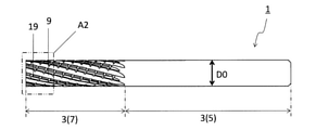
回転工具1(エンドミル)は、図1などに示すように、円柱形状の本体3を有してもよい。本体3は、回転軸R1に沿って第1端3aから第2端3bにかけて延びてもよい。一般的には、第1端3aが「先端」と呼ばれ、第2端3bが「後端」と呼ばれる。本体3は、切削加工物を製造するための被削材の切削加工時において、図1に示す限定されない態様のように回転軸R1を中心に矢印R2の方向に回転可能であってもよい。
As shown in FIG. 1 and the like, the rotary tool 1 (end mill) may have a cylindrical main body 3. The main body 3 may extend from the first end 3a to the second end 3b along the rotation axis R1. Generally, the first end 3a is called the "tip" and the second end 3b is called the "rear end". The main body 3 may be rotatable in the direction of the arrow R2 about the rotation axis R1 as in the non-limiting aspect shown in FIG. 1 when the work material for manufacturing a machined object is cut.
図1に示す限定されない態様において、本体3の右下側の端部が第1端3a、左上側の端部が第2端3bであってもよい。また、図4に示す限定されない態様において、本体3の左側の端部が第1端3a、右側の端部が第2端3bであってもよい。
In the non-limiting aspect shown in FIG. 1, the lower right end of the main body 3 may be the first end 3a and the upper left end may be the second end 3b. Further, in the non-limiting aspect shown in FIG. 4, the left end portion of the main body 3 may be the first end 3a and the right end portion may be the second end 3b.
本体3は、シャンク(shank)と呼ばれる把持部5及びボディー(body)と呼ばれる切削部7によって構成されてもよい。把持部5は、工作機械のスピンドル等で把持される部分であってもよい。把持部5の形状は、スピンドルの形状に応じて設計されてもよい。切削部7は、把持部5よりも第1端3aの側に位置してもよい。切削部7は、被削材と接触する部位であってもよい。すなわち、切削部7は、被削材の切削加工において主たる役割を有する部位であってもよい。
The main body 3 may be composed of a grip portion 5 called a shank and a cutting portion 7 called a body. The grip portion 5 may be a portion gripped by a spindle or the like of a machine tool. The shape of the grip portion 5 may be designed according to the shape of the spindle. The cutting portion 7 may be located closer to the first end 3a than the grip portion 5. The cutting portion 7 may be a portion that comes into contact with the work material. That is, the cutting portion 7 may be a portion having a main role in cutting the work material.
本体3の大きさは、特定の値には限定されない。例えば、本体3の直径(外径)D0が、5mm~40mmに設定されてもよい。また、切削部7の回転軸R1に沿った方向の長さは、1.5×D0mm~25×D0mm程度に設定されてもよい。
The size of the main body 3 is not limited to a specific value. For example, the diameter (outer diameter) D0 of the main body 3 may be set to 5 mm to 40 mm. Further, the length of the cutting portion 7 in the direction along the rotation axis R1 may be set to about 1.5 × D0 mm to 25 × D0 mm.
このとき、本体3の外径D0は、第1端3aの側から第2端3bの側にかけて一定であってもよく、変化してもよい。例えば、本体3の外径D0が、第1端3aの側から第2端3bの側にかけて小さくなってもよい。
At this time, the outer diameter D0 of the main body 3 may be constant or may change from the side of the first end 3a to the side of the second end 3b. For example, the outer diameter D0 of the main body 3 may become smaller from the side of the first end 3a to the side of the second end 3b.
本体3を構成する材質としては、例えば、金属、超硬合金、サーメット及びセラミックスなどが挙げられてもよい。金属としては、例えば、ステンレス及びチタンが挙げられてもよい。超硬合金の組成としては、例えば、WC(炭化タングステン)-Co(コバルト)、WC-TiC(炭化チタン)-Co、WC-TiC-TaC(炭化タンタル)-Co及びWC-TiC-TaC-Cr3C2(炭化クロム)-Coが挙げられてもよい。ここで、WC、TiC、TaC及びCr3C2は硬質粒子であってもよく、Coは結合相であってもよい。
Examples of the material constituting the main body 3 may include metal, cemented carbide, cermet, ceramics and the like. Examples of the metal may include stainless steel and titanium. The composition of the cemented carbide is, for example, WC (tungsten carbide) -Co (cobalt), WC-TiC (titanium carbide) -Co, WC-TiC-TaC (tantalum carbide) -Co and WC-TiC-TaC-Cr. 3 C 2 (chromium carbide) -Co may be mentioned. Here, WC, TiC, TaC and Cr 3 C 2 may be hard particles, and Co may be a bonded phase.
また、サーメットは、セラミック成分に金属を複合させた焼結複合材料であってもよい。具体的には、サーメットとして、TiC及びTiN(窒化チタン)などのチタン化合物を主成分としたものが一例として挙げられ得る。セラミックスとしては、例えば、Al2O3(酸化アルミニウム)、Si3N4(窒化珪素)及びcBN(立方晶窒化ホウ素:Cubic Boron Nitride)が挙げられ得る。
Further, the cermet may be a sintered composite material in which a metal is composited with a ceramic component. Specifically, as an example, a cermet containing a titanium compound such as TiC and TiN (titanium nitride) as a main component can be mentioned as an example. Examples of the ceramics include Al 2 O 3 (aluminum oxide), Si 3 N 4 (silicon nitride) and cBN (cubic Boron Nitride).
本体3は、上記の材質のみによって構成されてもよく、また、上記の材質によって構成された部材と、この部材を被覆する被覆層と、によって構成されてもよい。被覆層を構成する材質としては、例えば、ダイヤモンド、ダイヤモンドライクカーボン(DLC)、TiC、TiN、TiCN(炭窒化チタン)、TiMN(Mは、Ti以外の周期表4、5、6族金属、Al及びSiから選ばれる少なくとも1種の金属元素)、並びにAl2O3が挙げられ得る。本体3が、上記の被覆層を有する場合には、切刃の耐摩耗性を向上させ易い。
The main body 3 may be composed of only the above-mentioned material, or may be composed of a member made of the above-mentioned material and a coating layer covering the member. Examples of the material constituting the coating layer include diamond, diamond-like carbon (DLC), TiC, TiN, TiCN (titanium carbonitride), TiMN (M is a metal other than Ti, Group 4, 5 and 6 metals, Al). And at least one metal element selected from Si), as well as Al 2 O 3 . When the main body 3 has the above-mentioned coating layer, it is easy to improve the wear resistance of the cutting edge.
被覆層は、例えば気相合成法にて成膜してもよい。気相合成法としては、例えば、化学蒸着(CVD)法又は物理蒸着(PVD)法が挙げられ得る。被覆層の厚みは、例えば、0.3μm~20μmに設定されてもよい。なお、被覆層の組成によって好適な範囲は異なる。
The coating layer may be formed by, for example, a vapor phase synthesis method. Examples of the gas phase synthesis method may include a chemical vapor deposition (CVD) method or a physical vapor deposition (PVD) method. The thickness of the coating layer may be set to, for example, 0.3 μm to 20 μm. The suitable range varies depending on the composition of the coating layer.
本体3は、第1排出溝9、第1外周面11、第1稜線13、1つ以上の第1分断溝15、2つ以上の第1刃17、第2排出溝19、第2外周面21、第2稜線23、及び、1つ以上の第2刃25、を有してもよい。
The main body 3 has a first discharge groove 9, a first outer peripheral surface 11, a first ridge line 13, one or more first dividing grooves 15, two or more first blades 17, a second discharge groove 19, and a second outer peripheral surface. It may have 21, a second ridge 23, and one or more second blades 25.
第1排出溝9及び第2排出溝19は、それぞれ第1端3aから第2端3bに向かって延びてもよく、また、それぞれ切削加工において生じた切屑が流れる溝であってもよい。第1排出溝9及び第2排出溝19は、それぞれ回転軸R1に沿って真っすぐに延びた形状であってもよく、また、回転軸R1の周りでねじれた螺旋形状であってもよい。回転軸R1に直交する断面において、第1排出溝9及び第2排出溝19は、それぞれ凹曲線形状で示されてもよい。
The first discharge groove 9 and the second discharge groove 19 may extend from the first end 3a toward the second end 3b, respectively, or may be grooves through which chips generated in the cutting process flow. The first discharge groove 9 and the second discharge groove 19 may each have a shape extending straight along the rotation shaft R1 or a spiral shape twisted around the rotation shaft R1. In the cross section orthogonal to the rotation axis R1, the first discharge groove 9 and the second discharge groove 19 may be shown in a concave curved shape, respectively.
第1排出溝9及び第2排出溝19が回転軸R1の周りでねじれた螺旋形状である場合において、側面視における第1排出溝9及び第2排出溝19の回転軸R1に対する傾斜角は、ねじれ角と呼ばれ得る。ねじれ角は、第1排出溝9及び第2排出溝19における第1端3aの側の端部から第2端3bの側の端部にかけて一定であってもよく、また、変化してもよい。ねじれ角は、特定の値に限定されず、例えば10°~40°に設定されてもよい。
When the first discharge groove 9 and the second discharge groove 19 have a spiral shape twisted around the rotation shaft R1, the inclination angle of the first discharge groove 9 and the second discharge groove 19 with respect to the rotation axis R1 in the side view is set. It can be called the helix angle. The helix angle may be constant or variable from the end on the side of the first end 3a to the end on the side of the second end 3b in the first discharge groove 9 and the second discharge groove 19. .. The helix angle is not limited to a specific value and may be set to, for example, 10 ° to 40 °.
第1外周面11及び第2外周面21は、それぞれ凸曲面形状であってもよい。回転軸R1を含む断面において、第1外周面11及び第2外周面21は、それぞれ直線形状で示されてもよい。回転軸R1に直交する断面において、第1外周面11及び第2外周面21は、それぞれ凸曲線形状で示されてもよい。
The first outer peripheral surface 11 and the second outer peripheral surface 21 may each have a convex curved surface shape. In the cross section including the rotation axis R1, the first outer peripheral surface 11 and the second outer peripheral surface 21 may be shown in a linear shape, respectively. In the cross section orthogonal to the rotation axis R1, the first outer peripheral surface 11 and the second outer peripheral surface 21 may be shown in a convex curve shape, respectively.
第1外周面11は、第1排出溝9に対して回転軸R1の回転方向R2の後方に位置してもよい。第2排出溝19は、第1外周面11に対して回転方向R2の後方に位置してもよい。第2外周面21は、第2排出溝19に対して回転軸R1の回転方向R2の後方に位置してもよい。
The first outer peripheral surface 11 may be located behind the rotation direction R2 of the rotation shaft R1 with respect to the first discharge groove 9. The second discharge groove 19 may be located behind the first outer peripheral surface 11 in the rotation direction R2. The second outer peripheral surface 21 may be located behind the rotation direction R2 of the rotation shaft R1 with respect to the second discharge groove 19.
第1稜線13は、第1排出溝9及び第1外周面11の交わりに位置してもよい。2つ以上の第1刃17は、第1稜線13に位置してもよい。第1刃17は、第1稜線13の全体に位置してもよく、また、第1稜線13の一部に位置してもよい。第2稜線23は、第2排出溝19及び第2外周面21の交わりに位置してもよい。1つ以上の第2刃25は、第2稜線23に位置してもよい。第2刃25は、第2稜線23の全体に位置してもよく、また、第2稜線23の一部に位置してもよい。
The first ridge line 13 may be located at the intersection of the first discharge groove 9 and the first outer peripheral surface 11. Two or more first blades 17 may be located at the first ridge line 13. The first blade 17 may be located on the entire first ridge line 13 or may be located on a part of the first ridge line 13. The second ridge line 23 may be located at the intersection of the second discharge groove 19 and the second outer peripheral surface 21. One or more second blades 25 may be located at the second ridge line 23. The second blade 25 may be located on the entire second ridge line 23, or may be located on a part of the second ridge line 23.
1つ以上の第1分断溝15は、第1排出溝9から回転方向R2の後方に向かって延びてもよい。第1分断溝15が第1排出溝9から延びる場合には、第1稜線13が第1分断溝15によって複数の稜線部分に分断されてもよい。第1稜線13が分断される場合には、第1刃17が2つ以上であってもよい。第1分断溝15は、ニック溝と呼ばれ得る。また、第1分断溝15によって分断された複数の第1刃17は、ニック切刃と呼ばれ得る。第1分断溝15の数は、特定の値に限定されず、例えば3~7に設定されてもよい。
One or more first dividing grooves 15 may extend from the first discharge groove 9 toward the rear in the rotation direction R2. When the first dividing groove 15 extends from the first discharging groove 9, the first ridge line 13 may be divided into a plurality of ridge line portions by the first dividing groove 15. When the first ridge line 13 is divided, the number of first blades 17 may be two or more. The first dividing groove 15 may be called a nick groove. Further, the plurality of first blades 17 divided by the first dividing groove 15 may be referred to as nick cutting blades. The number of the first dividing grooves 15 is not limited to a specific value, and may be set to, for example, 3 to 7.
第1刃17が位置する第1稜線13を分断する第1分断溝15を本体3が有する場合には、第1刃17の耐久性が高い。本体3が複数の第1分断溝15を有する場合には、各第1分断溝15が第1排出溝9から延びてもよい。このとき、第1刃17が3つ以上であってもよい。
When the main body 3 has a first dividing groove 15 that divides the first ridge line 13 on which the first blade 17 is located, the durability of the first blade 17 is high. When the main body 3 has a plurality of first dividing grooves 15, each first dividing groove 15 may extend from the first discharge groove 9. At this time, the number of the first blades 17 may be three or more.
第1分断溝15は、回転軸R1に直交する方向から見た場合、言い換えれば側面視した場合に、回転軸R1に直交するように延びてもよく、また、回転軸R1に対して傾斜するように延びてもよい。例えば、側面視において、第1分断溝15は回転方向R2の後方に向かうにしたがって第2端3bに近づいてもよい。
The first dividing groove 15 may extend so as to be orthogonal to the rotation axis R1 when viewed from a direction orthogonal to the rotation axis R1, in other words, when viewed from the side, and may be inclined with respect to the rotation axis R1. It may be extended as follows. For example, in the side view, the first dividing groove 15 may approach the second end 3b toward the rear of the rotation direction R2.
第2刃25は、第2稜線23のうち第1分断溝15に対して回転方向R2の後方に少なくとも位置してもよい。言い換えると、第2稜線23に位置する第2刃25の少なくとも一部は、第1分断溝15に対して回転方向R2の後方に位置してもよい。第2刃25の全体が第1分断溝15に対して回転方向R2の後方に位置してもよい。
The second blade 25 may be located at least behind the rotation direction R2 with respect to the first dividing groove 15 of the second ridge line 23. In other words, at least a part of the second blade 25 located at the second ridge line 23 may be located behind the rotation direction R2 with respect to the first dividing groove 15. The entire second blade 25 may be located behind the rotation direction R2 with respect to the first dividing groove 15.
第1刃17及び第2刃25は、いわゆる外周刃として機能してもよい。本体3は、第1刃17及び第2刃25に加えて、いわゆる底刃27を複数有してもよい。複数の底刃27は、それぞれ本体3の第1端3aに位置してもよい。複数の底刃27は、第1刃17及び第2刃25に接続されてもよい。
The first blade 17 and the second blade 25 may function as so-called outer peripheral blades. The main body 3 may have a plurality of so-called bottom blades 27 in addition to the first blade 17 and the second blade 25. The plurality of bottom blades 27 may be located at the first end 3a of the main body 3, respectively. The plurality of bottom blades 27 may be connected to the first blade 17 and the second blade 25.
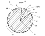
図6に示す限定されない一例のように、回転軸R1から第1稜線13までの長さが第1長さL1、回転軸R1から第2稜線23までの長さが第2長さL2であってもよい。また、図7に示す限定されない一例のように、回転軸R1に直交する断面において、第1排出溝9及び第1外周面11のなす角度が第1角度θ1、第2排出溝19及び第2外周面21のなす角度が第2角度θ2であってもよい。
As an example without limitation shown in FIG. 6, the length from the rotation axis R1 to the first ridge line 13 is the first length L1, and the length from the rotation axis R1 to the second ridge line 23 is the second length L2. You may. Further, as shown in FIG. 7, in a cross section orthogonal to the rotation axis R1, the angles formed by the first discharge groove 9 and the first outer peripheral surface 11 are the first angle θ1, the second discharge groove 19, and the second. The angle formed by the outer peripheral surface 21 may be the second angle θ2.
第2長さL2が第1長さL1より短くてもよい。また、第2角度θ2が第1角度θ1より大きくてもよい。第2刃25の少なくとも一部が第1分断溝15に対して回転方向R2の後方に位置するため、この一部には、大きな切削負荷が加わり易い。しかしながら、第2長さL2が、第1長さL1より短い場合には、切削加工時の第2刃25の切り込み深さが小さく抑えられる。そのため、第2刃25に加わる切削負荷が小さくなり得る。
The second length L2 may be shorter than the first length L1. Further, the second angle θ2 may be larger than the first angle θ1. Since at least a part of the second blade 25 is located behind the rotation direction R2 with respect to the first dividing groove 15, a large cutting load is likely to be applied to this part. However, when the second length L2 is shorter than the first length L1, the cutting depth of the second blade 25 at the time of cutting is suppressed to be small. Therefore, the cutting load applied to the second blade 25 can be reduced.
さらに、第2角度θ2が、第1角度θ1より大きい場合には、第2刃25の付近での本体3の肉厚が確保され易い。そのため、切削加工時の第2刃25の耐久性が高くなり易い。このように、第2刃25に加わる切削負荷が小さくなり、且つ、第2刃25の耐久性が高い。そのため、回転工具1の耐久性が高い。より具体的には、回転工具1は、ニックを有しつつ耐久性が高い。
Further, when the second angle θ2 is larger than the first angle θ1, it is easy to secure the wall thickness of the main body 3 in the vicinity of the second blade 25. Therefore, the durability of the second blade 25 during cutting tends to be high. In this way, the cutting load applied to the second blade 25 is reduced, and the durability of the second blade 25 is high. Therefore, the durability of the rotary tool 1 is high. More specifically, the rotary tool 1 has a nick and is highly durable.
第1長さL1及び第2長さL2は、特定の値には限定されない。例えば、第1長さL1が、0.45×D0mm~0.55×D0mmに設定されてもよい。また、第1長さL1及び第2長さL2の差δLが、0.005mm~0.1mmに設定されてもよい。
The first length L1 and the second length L2 are not limited to specific values. For example, the first length L1 may be set to 0.45 × D0 mm to 0.55 × D0 mm. Further, the difference δL between the first length L1 and the second length L2 may be set to 0.005 mm to 0.1 mm.
第1角度θ1及び第2角度θ2は、特定の値には限定されない。例えば、第1角度θ1が、50°~85°に設定されてもよい。また、第1角度θ1及び第2角度θ2の差δθが、5°~20°に設定されてもよい。
The first angle θ1 and the second angle θ2 are not limited to specific values. For example, the first angle θ1 may be set to 50 ° to 85 °. Further, the difference δθ between the first angle θ1 and the second angle θ2 may be set to 5 ° to 20 °.
図5に示す限定されない一例のように、側面視において、回転軸R1に直交する方向での第1外周面11の幅が第1幅W11、回転軸R1に直交する方向での第2外周面21の幅が第2幅W12であってもよい。このとき、第2幅W12が第1幅W11より大きくてもよい。
As an example without limitation shown in FIG. 5, in a side view, the width of the first outer peripheral surface 11 in the direction orthogonal to the rotation axis R1 is the first width W11, and the width of the second outer peripheral surface 11 is orthogonal to the rotation axis R1. The width of 21 may be the second width W12. At this time, the second width W12 may be larger than the first width W11.
第2幅W12が第1幅W11より大きい場合には、第2刃25の付近での本体3の肉厚が確保され易い。そのため、切削加工時の第2刃25の耐久性が高くなり易い。そのため、回転工具1の耐久性がさらに高い。
When the second width W12 is larger than the first width W11, it is easy to secure the wall thickness of the main body 3 in the vicinity of the second blade 25. Therefore, the durability of the second blade 25 during cutting tends to be high. Therefore, the durability of the rotary tool 1 is even higher.
第1幅W11及び第2幅W12は、特定の値には限定されない。例えば、第1幅W11が、0.005×D0mm~0.1×D0mmに設定されてもよい。また、第1幅W11及び第2幅W12の差δW1が、0.03mm~0.3mmに設定されてもよい。
The first width W11 and the second width W12 are not limited to specific values. For example, the first width W11 may be set to 0.005 × D0 mm to 0.1 × D0 mm. Further, the difference δW1 between the first width W11 and the second width W12 may be set to 0.03 mm to 0.3 mm.
本体3は、第2排出溝19から回転方向R2の後方に向かって延びた1つ以上の第2分断溝29をさらに有してもよい。第2分断溝29が第2排出溝19から延びる場合には、第2稜線23が第2分断溝29によって複数の稜線部分に分断されてもよい。第2稜線23が分断される場合には、第2刃25が2つ以上であってもよい。第2分断溝29は、第1分断溝15と同様にニック溝と呼ばれ得る。また、第2分断溝29によって分断された複数の第2刃25は、第1刃17と同様にニック切刃と呼ばれ得る。
The main body 3 may further have one or more second dividing grooves 29 extending from the second discharging groove 19 toward the rear in the rotation direction R2. When the second dividing groove 29 extends from the second discharging groove 19, the second ridge line 23 may be divided into a plurality of ridge line portions by the second dividing groove 29. When the second ridge line 23 is divided, the number of the second blades 25 may be two or more. The second dividing groove 29 may be called a nick groove like the first dividing groove 15. Further, the plurality of second blades 25 divided by the second dividing groove 29 may be called a nick cutting blade like the first blade 17.
第2長さL2が第1長さL1より短い場合には、第1刃17が第2刃25よりも回転軸R1から離れて位置する。回転方向R2の前方に位置する第1刃17が、回転方向R2の後方に位置する第2刃25よりも回転軸R1から離れて位置する場合には、第1刃17で生じる切屑の厚みが大きくなり易い。すなわち、第1刃17で生じる切屑が第2刃25で生じる切屑よりも多くなり易い。
When the second length L2 is shorter than the first length L1, the first blade 17 is located farther from the rotation axis R1 than the second blade 25. When the first blade 17 located in front of the rotation direction R2 is located farther from the rotation axis R1 than the second blade 25 located behind the rotation direction R2, the thickness of the chips generated by the first blade 17 is increased. It tends to grow. That is, the amount of chips generated by the first blade 17 tends to be larger than that generated by the second blade 25.
回転軸R1に直交する断面において、第1排出溝9の大きさ(スペース)が第2排出溝19の大きさよりも広い場合には、第1刃17で生じる切屑が第2刃25で生じる切屑より多くなっても、安定して切屑が処理され易い。
When the size (space) of the first discharge groove 9 is wider than the size of the second discharge groove 19 in the cross section orthogonal to the rotation axis R1, the chips generated by the first blade 17 are the chips generated by the second blade 25. Even if the amount is larger, chips are more likely to be processed stably.
図5に示す限定されない一例のように、側面視において、回転軸R1に直交する方向での第1排出溝9の幅が第1溝幅W21、回転軸R1に直交する方向での第2排出溝19の幅が第2溝幅W22であってもよい。このとき、回転軸R1に直交する断面における第1排出溝9の大きさを第2排出溝19の大きさよりも広くするため、第1溝幅W21が第2溝幅W22より大きくてもよい。
As an example without limitation shown in FIG. 5, in a side view, the width of the first discharge groove 9 in the direction orthogonal to the rotation axis R1 is the second discharge in the direction orthogonal to the first groove width W21 and the rotation axis R1. The width of the groove 19 may be the second groove width W22. At this time, in order to make the size of the first discharge groove 9 in the cross section orthogonal to the rotation axis R1 wider than the size of the second discharge groove 19, the first groove width W21 may be larger than the second groove width W22.
第1溝幅W21が第2溝幅W22より大きい場合には、回転軸R1に直交する断面において、第1排出溝9の大きさが第2排出溝19の大きさよりも広くなり易い。第1排出溝9の大きさが相対的に大きい場合には、第1刃17で生じる切屑が第2刃25で生じる切屑より多くなっても、安定して切屑が処理され易い。
When the first groove width W21 is larger than the second groove width W22, the size of the first discharge groove 9 tends to be wider than the size of the second discharge groove 19 in the cross section orthogonal to the rotation axis R1. When the size of the first discharge groove 9 is relatively large, even if the amount of chips generated by the first blade 17 is larger than that generated by the second blade 25, the chips are easily processed stably.
第1溝幅W21及び第2溝幅W22は、特定の値には限定されない。例えば、第1溝幅W21が、0.1×D0mm~0.5×D0mmに設定されてもよい。また、第1溝幅W21及び第2溝幅W22の差δW2が、0.5mm~5mmに設定されてもよい。
The first groove width W21 and the second groove width W22 are not limited to specific values. For example, the first groove width W21 may be set to 0.1 × D0 mm to 0.5 × D0 mm. Further, the difference δW2 between the first groove width W21 and the second groove width W22 may be set to 0.5 mm to 5 mm.
図7に示す限定されない一例のように、回転軸R1に直交する断面において、第1排出溝9の深さが第1溝深さD11、第2排出溝19の深さが第2溝深さD12であってもよい。このとき、第1溝深さD11が第2溝深さD12より深くてもよい。
As shown in FIG. 7, in a cross section orthogonal to the rotation axis R1, the depth of the first discharge groove 9 is the depth of the first groove D11, and the depth of the second discharge groove 19 is the depth of the second groove. It may be D12. At this time, the first groove depth D11 may be deeper than the second groove depth D12.
第1溝深さD11が第2溝深さD12より深い場合もまた、回転軸R1に直交する断面において、第1排出溝9の大きさが第2排出溝19の大きさよりも広くなり易い。第1排出溝9の大きさが相対的に大きい場合には、第1刃17で生じる切屑が第2刃25で生じる切屑より多くなっても、安定して切屑が処理され易い。
Also when the first groove depth D11 is deeper than the second groove depth D12, the size of the first discharge groove 9 tends to be wider than the size of the second discharge groove 19 in the cross section orthogonal to the rotation axis R1. When the size of the first discharge groove 9 is relatively large, even if the amount of chips generated by the first blade 17 is larger than that generated by the second blade 25, the chips are easily processed stably.
なお、本開示における溝深さとは、以下の手順によって評価されてもよい。まず、断面視した場合において、測定対象の溝での回転軸R1に最も近接する部分を溝底とする。次に、この溝底及び回転軸R1を通る仮想直線を設定する。また、本体3に対して外接する仮想円を設定する。このとき、仮想直線に沿った溝底から仮想円までの長さを溝深さとしてもよい。
The groove depth in the present disclosure may be evaluated by the following procedure. First, when viewed in cross section, the portion of the groove to be measured that is closest to the rotation axis R1 is defined as the groove bottom. Next, a virtual straight line passing through the groove bottom and the rotation axis R1 is set. Further, a virtual circle circumscribed with respect to the main body 3 is set. At this time, the length from the groove bottom along the virtual straight line to the virtual circle may be the groove depth.
第1溝深さD11及び第2溝深さD12は、特定の値には限定されない。例えば、第1溝深さD11が、0.05×D0mm~0.2×D0mmに設定されてもよい。また、第1溝深さD11及び第2溝深さD12の差δD1が、1mm~10mmに設定されてもよい。
The first groove depth D11 and the second groove depth D12 are not limited to specific values. For example, the first groove depth D11 may be set to 0.05 × D0 mm to 0.2 × D0 mm. Further, the difference δD1 between the first groove depth D11 and the second groove depth D12 may be set to 1 mm to 10 mm.
図7に示す限定されない一例のように、回転軸R1に直交する断面において、第1分断溝15の深さが溝深さD2であってもよい。このとき、第1溝深さD11が、第1分断溝15の溝深さD2より深くてもよい。
As an example without limitation shown in FIG. 7, the depth of the first dividing groove 15 may be the groove depth D2 in the cross section orthogonal to the rotation axis R1. At this time, the first groove depth D11 may be deeper than the groove depth D2 of the first dividing groove 15.
第1溝深さD11が第1分断溝15の溝深さD2より深い場合には、第1刃17で生じて第1排出溝9を流れる切屑が、第1分断溝15へと流れにくい。そのため、第1分断溝15における切屑の詰まりが生じにくい。また、第1排出溝9を流れる切屑が、第1分断溝15を通り第2排出溝19へと流れにくい。
When the first groove depth D11 is deeper than the groove depth D2 of the first dividing groove 15, the chips generated by the first blade 17 and flowing through the first discharge groove 9 are difficult to flow into the first dividing groove 15. Therefore, clogging of chips in the first dividing groove 15 is unlikely to occur. Further, it is difficult for chips flowing through the first discharge groove 9 to flow through the first dividing groove 15 to the second discharge groove 19.
溝深さD2は、特定の値には限定されない。例えば、溝深さD2が、0.05×D0mm~0.2×D0mmに設定されてもよい。また、第1溝深さD11及び溝深さD2の差δD2が、0.3mm~5mmに設定されてもよい。
The groove depth D2 is not limited to a specific value. For example, the groove depth D2 may be set to 0.05 × D0 mm to 0.2 × D0 mm. Further, the difference δD2 between the first groove depth D11 and the groove depth D2 may be set to 0.3 mm to 5 mm.
本体3は、第3排出溝31、第3外周面33、第3稜線35、及び、第3刃37、をさらに有してもよい。
The main body 3 may further have a third discharge groove 31, a third outer peripheral surface 33, a third ridge line 35, and a third blade 37.
第3排出溝31は、第1排出溝9及び第2排出溝19と同様に、第1端3aから第2端3bに向かって延びてもよく、また、切削加工において生じた切屑が流れる溝であってもよい。第3排出溝31は、第2外周面21に対して回転軸R1の回転方向R2の後方に位置してもよい。
Like the first discharge groove 9 and the second discharge groove 19, the third discharge groove 31 may extend from the first end 3a toward the second end 3b, and the groove through which chips generated during cutting flow flows. May be. The third discharge groove 31 may be located behind the rotation direction R2 of the rotation axis R1 with respect to the second outer peripheral surface 21.
第3排出溝31は、第1排出溝9及び第2排出溝19と同様に、回転軸R1に沿って真っすぐに延びた形状であってもよく、回転軸R1の周りでねじれた螺旋形状であってもよい。回転軸R1に直交する断面において、第3排出溝31は凹曲線形状で示されてもよい。
Like the first discharge groove 9 and the second discharge groove 19, the third discharge groove 31 may have a shape extending straight along the rotation shaft R1 and has a spiral shape twisted around the rotation shaft R1. There may be. In the cross section orthogonal to the rotation axis R1, the third discharge groove 31 may be shown in a concave curved shape.
第3外周面33は、第3排出溝31に対して回転軸R1の回転方向R2の後方に位置してもよい。第3外周面33は、第1外周面11及び第2外周面21と同様に、凸曲面形状であってもよい。第3外周面33は、回転軸R1を含む断面において、第1外周面11及び第2外周面21と同様に直線形状で示されてもよい。また、第3外周面33は、回転軸R1に直交する断面において、第1外周面11及び第2外周面21と同様に凸曲線形状で示されてもよい。
The third outer peripheral surface 33 may be located behind the rotation direction R2 of the rotation shaft R1 with respect to the third discharge groove 31. The third outer peripheral surface 33 may have a convex curved surface shape as in the first outer peripheral surface 11 and the second outer peripheral surface 21. The third outer peripheral surface 33 may be shown in a linear shape in the cross section including the rotation axis R1 in the same manner as the first outer peripheral surface 11 and the second outer peripheral surface 21. Further, the third outer peripheral surface 33 may be shown in a convex curved shape in a cross section orthogonal to the rotation axis R1 in the same manner as the first outer peripheral surface 11 and the second outer peripheral surface 21.
第3稜線35は、第3排出溝31及び第3外周面33の交わりに位置してもよい。1つ以上の第3刃37は、第3稜線35に位置してもよい。第3刃37は、第3稜線35の全体に位置してもよく、また、第3稜線35の一部に位置してもよい。第3刃37は、第1刃17及び第2刃25と同様に外周刃として機能してもよい。
The third ridge line 35 may be located at the intersection of the third discharge groove 31 and the third outer peripheral surface 33. One or more third blades 37 may be located at the third ridge line 35. The third blade 37 may be located on the entire third ridge line 35, or may be located on a part of the third ridge line 35. The third blade 37 may function as an outer peripheral blade in the same manner as the first blade 17 and the second blade 25.
図6に示す限定されない一例のように、回転軸R1から第3稜線35までの長さが第3長さL3であってもよい。このとき、第2長さL2が第3長さL3より短くてもよい。言い換えれば、第3長さL3が第2長さL2より長くてもよい。第3長さL3が第2長さL2より長い場合には、切削加工時の第2刃25において小さくなった切り込み深さが第3刃37において再度大きくなり易い。すなわち、切削加工時の加工面の面精度が向上し易い。
As an example without limitation shown in FIG. 6, the length from the rotation axis R1 to the third ridge line 35 may be the third length L3. At this time, the second length L2 may be shorter than the third length L3. In other words, the third length L3 may be longer than the second length L2. When the third length L3 is longer than the second length L2, the cutting depth reduced in the second blade 25 during cutting tends to increase again in the third blade 37. That is, the surface accuracy of the machined surface during cutting is likely to be improved.
第3長さL3が第1長さL1と同じであってもよい。第3長さL3が第1長さL1と同じである場合には、切削加工時の加工面の面精度がさらに向上し易い。なお、第3長さL3が第1長さL1と同じであるとは、2つの長さの値が厳密に同じでなくてもよい。具体的には、第3長さL3に対する2つの長さの差(L3-L1)の値((L3-L1)/L3)が、-0.05~0.05程度である場合に、第3長さL3が第1長さL1と同じであると見做してもよい。
The third length L3 may be the same as the first length L1. When the third length L3 is the same as the first length L1, the surface accuracy of the machined surface during cutting is likely to be further improved. It should be noted that the third length L3 is the same as the first length L1 and the values of the two lengths do not have to be exactly the same. Specifically, when the value ((L3-L1) / L3) of the difference (L3-L1) between the two lengths with respect to the third length L3 is about −0.05 to 0.05, the third length. 3 The length L3 may be regarded as the same as the first length L1.
<切削加工物(machined product)の製造方法>
次に、実施形態の切削加工物101の製造方法について、上述の実施形態に係る回転工具を用いる場合を例に挙げて詳細に説明する。以下、図8~図10を参照しつつ説明する。なお、図8~図10においては、切削加工物101の製造方法の一例として、被削材103への肩加工の工程を図示している。また、視覚的な理解を容易にするため、図9及び図10において、回転工具1によって切削された加工面にハッチングを付している。 <Manufacturing method of machined product>
Next, the method of manufacturing the machinedobject 101 of the embodiment will be described in detail with reference to the case where the rotary tool according to the above-described embodiment is used as an example. Hereinafter, description will be made with reference to FIGS. 8 to 10. Note that FIGS. 8 to 10 show a process of shoulder processing on the work material 103 as an example of a method for manufacturing the machined object 101. Further, in order to facilitate visual understanding, in FIGS. 9 and 10, the machined surface cut by the rotary tool 1 is hatched.
次に、実施形態の切削加工物101の製造方法について、上述の実施形態に係る回転工具を用いる場合を例に挙げて詳細に説明する。以下、図8~図10を参照しつつ説明する。なお、図8~図10においては、切削加工物101の製造方法の一例として、被削材103への肩加工の工程を図示している。また、視覚的な理解を容易にするため、図9及び図10において、回転工具1によって切削された加工面にハッチングを付している。 <Manufacturing method of machined product>
Next, the method of manufacturing the machined
実施形態にかかる切削加工物101の製造方法は、以下の(1)~(3)の工程を備えてもよい。
The method for manufacturing the machined product 101 according to the embodiment may include the following steps (1) to (3).
(1)回転工具1を、回転軸R1を中心に矢印R2の方向に回転させ、被削材103に向かってY1方向に回転工具1を近づける(図8参照)。
(1) Rotate the rotary tool 1 in the direction of the arrow R2 about the rotary shaft R1 and bring the rotary tool 1 closer to the work material 103 in the Y1 direction (see FIG. 8).
本工程は、例えば、被削材103を、回転工具1を取り付けた工作機械のテーブル上に固定し、回転工具1を回転した状態で近づけることにより行うことができる。なお、本工程では、被削材103と回転工具1とは相対的に近づけばよく、被削材103を回転工具1に近づけてもよい。
This step can be performed, for example, by fixing the work material 103 on the table of the machine tool to which the rotary tool 1 is attached and bringing the rotary tool 1 closer in a rotated state. In this step, the work material 103 and the rotary tool 1 may be relatively close to each other, and the work material 103 may be relatively close to the rotary tool 1.
(2)回転工具1をさらに被削材103に近づけることによって、回転している回転工具1を被削材103の表面の所望の位置に接触させて、被削材103を切削する(図9参照)。
(2) By bringing the rotary tool 1 closer to the work material 103, the rotating rotary tool 1 is brought into contact with a desired position on the surface of the work material 103, and the work material 103 is cut (FIG. 9). reference).
本工程においては、第1刃17及び第2刃25を被削材103の表面の所望の位置に接触させている。なお、切削加工としては、例えば、図9に示すような肩加工の他にも、溝加工及びフライス加工などが挙げられる。
In this step, the first blade 17 and the second blade 25 are brought into contact with a desired position on the surface of the work material 103. Examples of the cutting process include groove processing and milling processing in addition to the shoulder processing as shown in FIG.
(3)回転工具1を被削材103からY2方向に離す(図10参照)。
(3) Separate the rotary tool 1 from the work material 103 in the Y2 direction (see FIG. 10).
本工程においても、上述の(1)の工程と同様に、被削材103から回転工具1を相対的に離せばよく、例えば被削材103を回転工具1から離してもよい。
In this step as well, as in the step (1) described above, the rotary tool 1 may be relatively separated from the work material 103, and for example, the work material 103 may be separated from the rotary tool 1.
以上のような工程を経る場合には、優れた加工性を発揮することが可能となる。
When going through the above steps, it is possible to demonstrate excellent workability.
なお、以上に示したような被削材103の切削加工を複数回行う場合であって、例えば、1つの被削材103に対して複数の切削加工を行う場合には、回転工具1を回転させた状態を保持しつつ、被削材103の異なる箇所に回転工具1を接触させる工程を繰り返してもよい。
In addition, in the case where the cutting process of the work material 103 as shown above is performed a plurality of times, for example, when a plurality of cutting processes are performed on one work material 103, the rotary tool 1 is rotated. The step of bringing the rotary tool 1 into contact with different parts of the work material 103 may be repeated while maintaining the state of being kept.
1・・・回転工具(エンドミル)
3・・・本体
3a・・第1端
3b・・第2端
5・・・把持部
7・・・切削部
9・・・第1排出溝
11・・・第1外周面
13・・・第1稜線
15・・・第1分断溝
17・・・第1刃
19・・・第2排出溝
21・・・第2外周面
23・・・第2稜線
25・・・第2刃
27・・・底刃
29・・・第2分断溝
31・・・第3排出溝
33・・・第3外周面
35・・・第3稜線
37・・・第3刃
101・・・切削加工物
103・・・被削材
R1・・・回転軸
R2・・・回転方向
L1・・・第1長さ
L2・・・第2長さ
L3・・・第3長さ
θ1・・・第1角度
θ2・・・第2角度
W11・・・第1幅
W12・・・第2幅
W21・・・第1溝幅
W22・・・第2溝幅
D11・・・第1溝深さ
D12・・・第2溝深さ 1 ... Rotary tool (end mill)
3 ... Main body 3a ...1st end 3b ... 2nd end 5 ... Grip part 7 ... Cutting part 9 ... 1st discharge groove 11 ... 1st outer peripheral surface 13 ... 1 ridge line 15 ... 1st dividing groove 17 ... 1st blade 19 ... 2nd discharge groove 21 ... 2nd outer peripheral surface 23 ... 2nd ridge line 25 ... 2nd blade 27 ...・ Bottom blade 29 ・ ・ ・ 2nd dividing groove 31 ・ ・ ・ 3rd discharge groove 33 ・ ・ ・ 3rd outer peripheral surface 35 ・ ・ ・ 3rd ridge line 37 ・ ・ ・ 3rd blade 101 ・ ・ ・ Machined work 103 ・・ ・ Work material R1 ・ ・ ・ Rotation axis R2 ・ ・ ・ Rotation direction L1 ・ ・ ・ First length L2 ・ ・ ・ Second length L3 ・ ・ ・ Third length θ1 ・ ・ ・ First angle θ2 ・2nd angle W11 ... 1st width W12 ... 2nd width W21 ... 1st groove width W22 ... 2nd groove width D11 ... 1st groove depth D12 ... 2nd Groove depth
3・・・本体
3a・・第1端
3b・・第2端
5・・・把持部
7・・・切削部
9・・・第1排出溝
11・・・第1外周面
13・・・第1稜線
15・・・第1分断溝
17・・・第1刃
19・・・第2排出溝
21・・・第2外周面
23・・・第2稜線
25・・・第2刃
27・・・底刃
29・・・第2分断溝
31・・・第3排出溝
33・・・第3外周面
35・・・第3稜線
37・・・第3刃
101・・・切削加工物
103・・・被削材
R1・・・回転軸
R2・・・回転方向
L1・・・第1長さ
L2・・・第2長さ
L3・・・第3長さ
θ1・・・第1角度
θ2・・・第2角度
W11・・・第1幅
W12・・・第2幅
W21・・・第1溝幅
W22・・・第2溝幅
D11・・・第1溝深さ
D12・・・第2溝深さ 1 ... Rotary tool (end mill)
3 ... Main body 3a ...
Claims (7)
- 回転軸に沿って第1端から第2端にかけて延びた円柱形状の本体を有し、
前記本体は、
前記第1端から前記第2端に向かって延びた第1排出溝と、
前記第1排出溝に対して前記回転軸の回転方向の後方に位置する第1外周面と、
前記第1排出溝及び前記第1外周面の交わりに位置する第1稜線と、
前記第1排出溝から前記回転方向の後方に向かって延び、前記第1稜線を分断する分断溝と、
前記第1稜線に位置し、前記分断溝によって分断された2つ以上の第1刃と、
前記第1外周面に対して前記回転方向の後方に位置し、前記第1端から前記第2端に向かって延びた第2排出溝と、
前記第2排出溝に対して前記回転方向の後方に位置する第2外周面と、
前記第2排出溝及び前記第2外周面の交わりに位置する第2稜線と、
前記第2稜線のうち前記分断溝に対して前記回転方向の後方に少なくとも位置する第2刃と、を有し、
前記回転軸から前記第1稜線までの長さが第1長さ、前記回転軸から前記第2稜線までの長さが第2長さであって、
前記第2長さが、前記第1長さよりも短く、
前記回転軸に直交する断面において、前記第1排出溝及び前記第1外周面のなす角度が第1角度、前記第2排出溝及び前記第2外周面のなす角度が第2角度であって、
前記第2角度が、前記第1角度よりも大きい、回転工具。 It has a cylindrical body that extends from the first end to the second end along the axis of rotation.
The main body is
A first discharge groove extending from the first end toward the second end,
A first outer peripheral surface located behind the rotation axis in the rotation direction with respect to the first discharge groove,
The first ridge line located at the intersection of the first discharge groove and the first outer peripheral surface,
A dividing groove extending from the first discharge groove toward the rear in the rotational direction and dividing the first ridgeline,
Two or more first blades located on the first ridgeline and divided by the dividing groove,
A second discharge groove located rearward in the rotational direction with respect to the first outer peripheral surface and extending from the first end toward the second end.
A second outer peripheral surface located behind the second discharge groove in the rotational direction,
A second ridge line located at the intersection of the second discharge groove and the second outer peripheral surface,
The second ridge line has a second blade located at least behind the dividing groove in the rotational direction.
The length from the rotation axis to the first ridge line is the first length, and the length from the rotation axis to the second ridge line is the second length.
The second length is shorter than the first length,
In the cross section orthogonal to the rotation axis, the angle formed by the first discharge groove and the first outer peripheral surface is the first angle, and the angle formed by the second discharge groove and the second outer peripheral surface is the second angle.
A rotary tool in which the second angle is larger than the first angle. - 側面視において、前記回転軸に直交する方向での前記第1外周面の幅が第1幅、前記回転軸に直交する方向での前記第2外周面の幅が第2幅であって、
前記第2幅が、前記第1幅よりも大きい、請求項1に記載の回転工具。 In the side view, the width of the first outer peripheral surface in the direction orthogonal to the rotation axis is the first width, and the width of the second outer peripheral surface in the direction orthogonal to the rotation axis is the second width.
The rotary tool according to claim 1, wherein the second width is larger than the first width. - 側面視において、前記回転軸に直交する方向での前記第1排出溝の幅が第1溝幅、前記回転軸に直交する方向での前記第2排出溝の幅が第2溝幅であって、
前記第1溝幅が、前記第2溝幅よりも大きい、請求項1又は2に記載の回転工具。 In the side view, the width of the first discharge groove in the direction orthogonal to the rotation axis is the first groove width, and the width of the second discharge groove in the direction orthogonal to the rotation axis is the second groove width. ,
The rotary tool according to claim 1 or 2, wherein the first groove width is larger than the second groove width. - 前記回転軸に直交する断面において、前記第1排出溝の深さが第1溝深さ、前記第2排出溝の深さが第2溝深さであって、
前記第1溝深さが、前記第2溝深さよりも深い、請求項1~3のいずれか1つに記載の回転工具。 In the cross section orthogonal to the rotation axis, the depth of the first discharge groove is the depth of the first groove, and the depth of the second discharge groove is the depth of the second groove.
The rotary tool according to any one of claims 1 to 3, wherein the depth of the first groove is deeper than the depth of the second groove. - 前記第1溝深さが、前記分断溝の溝深さよりも深い、請求項4に記載の回転工具。 The rotary tool according to claim 4, wherein the depth of the first groove is deeper than the depth of the dividing groove.
- 前記本体は、
前記第2外周面に対して前記回転方向の後方に位置し、前記第1端から前記第2端に向かって延びた第3排出溝と、
前記第3排出溝に対して前記回転方向の後方に位置する第3外周面と、
前記第3排出溝及び前記第3外周面の交わりに位置する第3稜線と、
前記第3稜線に位置する第3刃と、をさらに有し、
前記回転軸から前記第3稜線までの長さが第3長さであって、
前記第2長さが、前記第3長さよりも短い、請求項1~5のいずれか1つに記載の回転工具。 The main body is
A third discharge groove located rearward in the rotational direction with respect to the second outer peripheral surface and extending from the first end toward the second end.
A third outer peripheral surface located behind the third discharge groove in the rotational direction,
A third ridge line located at the intersection of the third discharge groove and the third outer peripheral surface,
Further having a third blade located at the third ridgeline,
The length from the rotation axis to the third ridge line is the third length.
The rotary tool according to any one of claims 1 to 5, wherein the second length is shorter than the third length. - 請求項1~6のいずれか1つに記載の回転工具を回転させる工程と、
前記回転工具を被削材に接触させる工程と、
前記回転工具を前記被削材から離す工程と、を備えた切削加工物の製造方法。 The step of rotating the rotary tool according to any one of claims 1 to 6,
The process of bringing the rotary tool into contact with the work material and
A method for manufacturing a machined product, comprising a step of separating the rotary tool from the work material.
Priority Applications (1)
| Application Number | Priority Date | Filing Date | Title |
|---|---|---|---|
| JP2022544011A JP7465980B2 (en) | 2020-08-20 | 2021-08-20 | Method for manufacturing rotary tools and machined products |
Applications Claiming Priority (2)
| Application Number | Priority Date | Filing Date | Title |
|---|---|---|---|
| JP2020139440 | 2020-08-20 | ||
| JP2020-139440 | 2020-08-20 |
Publications (1)
| Publication Number | Publication Date |
|---|---|
| WO2022039248A1 true WO2022039248A1 (en) | 2022-02-24 |
Family
ID=80323557
Family Applications (1)
| Application Number | Title | Priority Date | Filing Date |
|---|---|---|---|
| PCT/JP2021/030500 WO2022039248A1 (en) | 2020-08-20 | 2021-08-20 | Rotating tool and method for manufacturing cut workpieces |
Country Status (2)
| Country | Link |
|---|---|
| JP (1) | JP7465980B2 (en) |
| WO (1) | WO2022039248A1 (en) |
Citations (6)
| Publication number | Priority date | Publication date | Assignee | Title |
|---|---|---|---|---|
| JPH01114223U (en) * | 1988-01-23 | 1989-08-01 | ||
| JPH0340017U (en) * | 1989-08-31 | 1991-04-17 | ||
| JP2018529541A (en) * | 2015-09-29 | 2018-10-11 | フランケン ゲゼルシャフト ミット ベシュレンクテル ハフツング ウント コンパニー コマンディートゲゼルシャフト ファブリク フュア プレツィズィオンスヴェルクツォイゲFranken GmbH & Co. KG Fabrik fuer Praezisionswerkzeuge | Finishing tools, especially tip milling cutters |
| JP2019508270A (en) * | 2016-02-02 | 2019-03-28 | サンドビック インテレクチュアル プロパティー アクティエボラーグ | Tool with right-turn and left-turn cutting features extending along the entire length of the cutting zone |
| JP2020093374A (en) * | 2018-12-14 | 2020-06-18 | 京セラ株式会社 | Cutting insert, cutting tool and manufacturing method for work-piece to be cut |
| EP3695928A1 (en) * | 2019-02-14 | 2020-08-19 | CERATIZIT Balzheim GmbH & Co. KG | Milling tool for machining fibre composites |
-
2021
- 2021-08-20 JP JP2022544011A patent/JP7465980B2/en active Active
- 2021-08-20 WO PCT/JP2021/030500 patent/WO2022039248A1/en active Application Filing
Patent Citations (6)
| Publication number | Priority date | Publication date | Assignee | Title |
|---|---|---|---|---|
| JPH01114223U (en) * | 1988-01-23 | 1989-08-01 | ||
| JPH0340017U (en) * | 1989-08-31 | 1991-04-17 | ||
| JP2018529541A (en) * | 2015-09-29 | 2018-10-11 | フランケン ゲゼルシャフト ミット ベシュレンクテル ハフツング ウント コンパニー コマンディートゲゼルシャフト ファブリク フュア プレツィズィオンスヴェルクツォイゲFranken GmbH & Co. KG Fabrik fuer Praezisionswerkzeuge | Finishing tools, especially tip milling cutters |
| JP2019508270A (en) * | 2016-02-02 | 2019-03-28 | サンドビック インテレクチュアル プロパティー アクティエボラーグ | Tool with right-turn and left-turn cutting features extending along the entire length of the cutting zone |
| JP2020093374A (en) * | 2018-12-14 | 2020-06-18 | 京セラ株式会社 | Cutting insert, cutting tool and manufacturing method for work-piece to be cut |
| EP3695928A1 (en) * | 2019-02-14 | 2020-08-19 | CERATIZIT Balzheim GmbH & Co. KG | Milling tool for machining fibre composites |
Also Published As
| Publication number | Publication date |
|---|---|
| JPWO2022039248A1 (en) | 2022-02-24 |
| JP7465980B2 (en) | 2024-04-11 |
Similar Documents
| Publication | Publication Date | Title |
|---|---|---|
| CN112672840B (en) | Cutting insert, rotary tool, and method for manufacturing cut product | |
| JP6860657B2 (en) | Manufacturing method for rotary tools and cuttings | |
| JP6711830B2 (en) | Drill and method of manufacturing cut product using the same | |
| JPWO2018180775A1 (en) | Rotary tool | |
| JP7103933B2 (en) | Manufacturing method for cutting inserts, rotary tools and machined products | |
| CN110709201B (en) | End mill and method for manufacturing cut product | |
| WO2016186217A1 (en) | Holder, cutting tool, and method for manufacturing cut product using same | |
| WO2022039248A1 (en) | Rotating tool and method for manufacturing cut workpieces | |
| JP7163166B2 (en) | Manufacturing method for rotary tool and cut product | |
| JP7417707B2 (en) | End mill and method for manufacturing cut products | |
| JP6839015B2 (en) | Drill | |
| JP6748232B2 (en) | Method for manufacturing rotating tool and cutting product | |
| WO2021153599A1 (en) | Rotating tool and method for manufacturing cut workpieces | |
| JP7279163B2 (en) | Manufacturing method for rotary tool and cut product | |
| WO2022054829A1 (en) | Cutting insert, rotary tool, and method for manufacturing cut product | |
| WO2021230176A1 (en) | Drill and method for manufacturing cut workpiece | |
| JP7060462B2 (en) | Manufacturing method for rotary tools and cuttings | |
| CN114786850A (en) | Drill and method for manufacturing cut product | |
| JP2020069558A (en) | Rotary tool and manufacturing method for cutting work-piece | |
| JP2021100772A (en) | Rotary tool and cut product manufacturing method |
Legal Events
| Date | Code | Title | Description |
|---|---|---|---|
| 121 | Ep: the epo has been informed by wipo that ep was designated in this application |
Ref document number: 21858391 Country of ref document: EP Kind code of ref document: A1 |
|
| ENP | Entry into the national phase |
Ref document number: 2022544011 Country of ref document: JP Kind code of ref document: A |
|
| NENP | Non-entry into the national phase |
Ref country code: DE |
|
| 122 | Ep: pct application non-entry in european phase |
Ref document number: 21858391 Country of ref document: EP Kind code of ref document: A1 |