WO2021256345A1 - 吸収性物品 - Google Patents
吸収性物品 Download PDFInfo
- Publication number
- WO2021256345A1 WO2021256345A1 PCT/JP2021/021931 JP2021021931W WO2021256345A1 WO 2021256345 A1 WO2021256345 A1 WO 2021256345A1 JP 2021021931 W JP2021021931 W JP 2021021931W WO 2021256345 A1 WO2021256345 A1 WO 2021256345A1
- Authority
- WO
- WIPO (PCT)
- Prior art keywords
- pad
- absorbent article
- mark
- edge
- mark portion
- Prior art date
- Legal status (The legal status is an assumption and is not a legal conclusion. Google has not performed a legal analysis and makes no representation as to the accuracy of the status listed.)
- Ceased
Links
Images



Classifications
-
- A—HUMAN NECESSITIES
- A61—MEDICAL OR VETERINARY SCIENCE; HYGIENE
- A61F—FILTERS IMPLANTABLE INTO BLOOD VESSELS; PROSTHESES; DEVICES PROVIDING PATENCY TO, OR PREVENTING COLLAPSING OF, TUBULAR STRUCTURES OF THE BODY, e.g. STENTS; ORTHOPAEDIC, NURSING OR CONTRACEPTIVE DEVICES; FOMENTATION; TREATMENT OR PROTECTION OF EYES OR EARS; BANDAGES, DRESSINGS OR ABSORBENT PADS; FIRST-AID KITS
- A61F13/00—Bandages or dressings; Absorbent pads
- A61F13/15—Absorbent pads, e.g. sanitary towels, swabs or tampons for external or internal application to the body; Supporting or fastening means therefor; Tampon applicators
- A61F13/45—Absorbent pads, e.g. sanitary towels, swabs or tampons for external or internal application to the body; Supporting or fastening means therefor; Tampon applicators characterised by the shape
- A61F13/49—Absorbent pads, e.g. sanitary towels, swabs or tampons for external or internal application to the body; Supporting or fastening means therefor; Tampon applicators characterised by the shape specially adapted to be worn around the waist, e.g. diapers or nappies
- A61F13/493—Absorbent pads, e.g. sanitary towels, swabs or tampons for external or internal application to the body; Supporting or fastening means therefor; Tampon applicators characterised by the shape specially adapted to be worn around the waist, e.g. diapers or nappies adjustable by adding or removing material, e.g. umbilical cord arrangements
-
- A—HUMAN NECESSITIES
- A61—MEDICAL OR VETERINARY SCIENCE; HYGIENE
- A61F—FILTERS IMPLANTABLE INTO BLOOD VESSELS; PROSTHESES; DEVICES PROVIDING PATENCY TO, OR PREVENTING COLLAPSING OF, TUBULAR STRUCTURES OF THE BODY, e.g. STENTS; ORTHOPAEDIC, NURSING OR CONTRACEPTIVE DEVICES; FOMENTATION; TREATMENT OR PROTECTION OF EYES OR EARS; BANDAGES, DRESSINGS OR ABSORBENT PADS; FIRST-AID KITS
- A61F13/00—Bandages or dressings; Absorbent pads
- A61F13/15—Absorbent pads, e.g. sanitary towels, swabs or tampons for external or internal application to the body; Supporting or fastening means therefor; Tampon applicators
- A61F13/45—Absorbent pads, e.g. sanitary towels, swabs or tampons for external or internal application to the body; Supporting or fastening means therefor; Tampon applicators characterised by the shape
- A61F13/49—Absorbent pads, e.g. sanitary towels, swabs or tampons for external or internal application to the body; Supporting or fastening means therefor; Tampon applicators characterised by the shape specially adapted to be worn around the waist, e.g. diapers or nappies
- A61F13/494—Absorbent pads, e.g. sanitary towels, swabs or tampons for external or internal application to the body; Supporting or fastening means therefor; Tampon applicators characterised by the shape specially adapted to be worn around the waist, e.g. diapers or nappies characterised by edge leakage prevention means
-
- A—HUMAN NECESSITIES
- A61—MEDICAL OR VETERINARY SCIENCE; HYGIENE
- A61F—FILTERS IMPLANTABLE INTO BLOOD VESSELS; PROSTHESES; DEVICES PROVIDING PATENCY TO, OR PREVENTING COLLAPSING OF, TUBULAR STRUCTURES OF THE BODY, e.g. STENTS; ORTHOPAEDIC, NURSING OR CONTRACEPTIVE DEVICES; FOMENTATION; TREATMENT OR PROTECTION OF EYES OR EARS; BANDAGES, DRESSINGS OR ABSORBENT PADS; FIRST-AID KITS
- A61F13/00—Bandages or dressings; Absorbent pads
- A61F13/15—Absorbent pads, e.g. sanitary towels, swabs or tampons for external or internal application to the body; Supporting or fastening means therefor; Tampon applicators
- A61F13/505—Absorbent pads, e.g. sanitary towels, swabs or tampons for external or internal application to the body; Supporting or fastening means therefor; Tampon applicators with separable parts, e.g. combination of disposable and reusable parts
-
- A—HUMAN NECESSITIES
- A61—MEDICAL OR VETERINARY SCIENCE; HYGIENE
- A61F—FILTERS IMPLANTABLE INTO BLOOD VESSELS; PROSTHESES; DEVICES PROVIDING PATENCY TO, OR PREVENTING COLLAPSING OF, TUBULAR STRUCTURES OF THE BODY, e.g. STENTS; ORTHOPAEDIC, NURSING OR CONTRACEPTIVE DEVICES; FOMENTATION; TREATMENT OR PROTECTION OF EYES OR EARS; BANDAGES, DRESSINGS OR ABSORBENT PADS; FIRST-AID KITS
- A61F13/00—Bandages or dressings; Absorbent pads
- A61F13/15—Absorbent pads, e.g. sanitary towels, swabs or tampons for external or internal application to the body; Supporting or fastening means therefor; Tampon applicators
- A61F13/56—Supporting or fastening means
Definitions
- the present invention relates to an absorbent article having a pair of leak-proof cuffs and to which an absorbent pad can be attached.
- Patent Document 1 discloses an absorbent article having a pair of leak-proof cuffs and to which an absorbent pad can be attached.
- the leak-proof cuff has an upright portion that can stand up toward the skin surface side due to contraction in the anteroposterior direction.
- the mounting assistant attaches the absorbent pad to the absorbent article
- the absorbent pad is arranged between the standing portions by inserting the absorbent pad into the non-skin surface side of the standing portion.
- the wearing assistant does not insert the absorbent pad into the non-skin surface side of the upright portion, but instead puts the absorbent pad on the leak-proof cuff (that is, the skin of the upright portion). It was sometimes placed on the surface side). In this case, since the absorption pad hinders the standing of the standing portion, lateral leakage of excrement is likely to occur. Further, since the absorbent pad is not fixed, the absorbent pad may be displaced due to the movement of the wearer, and the wearing feeling of the absorbent article may be deteriorated.
- an absorbent article having a pair of leak-proof cuffs and to which an absorbent pad can be attached, which is easy to induce the absorbent pad to be inserted into the non-skin surface side of the upright portion.
- the purpose is.
- the absorbent article is arranged on both sides of the width direction orthogonal to the front-rear direction and the front-rear direction and the width center extending in the front-rear direction and being the center of the width direction of the absorbent article. It has a pair of leak-proof cuffs.
- the leak-proof cuff is located at an upright portion that can stand up from the upright edge toward the skin surface side due to contraction in the anteroposterior direction, and outside the upright portion in the anteroposterior direction, and faces the skin surface side. It has an anterior-posterior joint that is joined so as not to stand up.
- the absorbent article can be fitted with an absorbent pad.
- the absorbent article has a marking portion indicating the arrangement position of the end portion of the absorbent pad in the front-rear direction. At least a part of the mark portion is arranged outside the upright edge in the width direction and inside the front-rear joint portion in the front-rear direction.
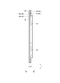
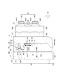
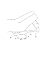
- FIG. 1 is a schematic plan view of the absorbent article according to the embodiment as viewed from the skin surface side.
- FIG. 2 is a schematic cross-sectional view taken along the line F2-F2 shown in FIG.
- FIG. 3 is a schematic partially enlarged plan view of the absorbent article according to the embodiment as viewed from the skin surface side.
- FIG. 4 is a schematic cross-sectional view taken along the line F4-F4 shown in FIG.
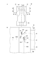
- FIG. 5A is a schematic plan view of the absorbent article as viewed from the skin surface side in a state where the absorbent pad is attached to the absorbent article according to the embodiment
- FIG. 5B is a schematic view of the absorbent article of FIG. 5A. It is a partially enlarged plan view.
- FIG. 5A is a schematic plan view of the absorbent article according to the embodiment as viewed from the skin surface side.
- FIG. 5B is a schematic view of the absorbent article of FIG. 5A. It is a partially enlarged plan view.
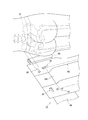
- FIG. 6 is a diagram for explaining a mounting state of the absorbent article according to the embodiment.
- FIG. 7 is a diagram for explaining a mounting state of the absorbent article according to the embodiment.
- FIG. 8 is a diagram for explaining a mounting state of the absorbent article according to the embodiment.
- the absorbent article has a width direction orthogonal to the front-rear direction and the front-rear direction, and a width center extending in the front-rear direction and being the center of the width direction of the absorbent article. It has a pair of leak-proof cuffs, which are arranged on both sides of the cuff.
- the leak-proof cuff is located at an upright portion that can stand up from the upright edge toward the skin surface side due to contraction in the anteroposterior direction, and outside the upright portion in the anteroposterior direction, and faces the skin surface side. It has an anterior-posterior joint that is joined so as not to stand up.
- the absorbent article can be fitted with an absorbent pad.
- the absorbent article has a marking portion indicating the arrangement position of the end portion of the absorbent pad in the front-rear direction. At least a part of the mark portion is arranged outside the upright edge in the width direction and inside the front-rear joint portion in the front-rear direction.
- the mounting assistant aligns the end of the absorbent pad with the position indicated by the marker, it not only visually recognizes the marker, but also the position of the center of the absorbent pad in the width direction at the center of the width of the absorbent article. Visualize the center of the width to match. Therefore, in the above-mentioned absorbent article, at least a part of the mark portion is arranged outside the standing edge in the width direction and inside the front-rear joint portion in the front-rear direction.
- the wearing assistant can easily recognize the leak-proof cuff by visually recognizing the standing portion, and can induce the wearing assistant to insert the absorption pad into the non-skin surface side of the standing portion.
- the length from the front-rear joint portion to the mark portion may be shorter than the maximum length of the mark portion in the front-rear direction.
- the mark portion since the mark portion is arranged close to the front-rear joint portion, the upright edge of the upright portion in the front-rear direction (that is, the inner end edge of the front-rear joint portion) and the upright end edge of the upright portion in the width direction.
- the corners of the pockets (spaces) that are constructed are easier to see. Since the outer edge (that is, the corner) of the end of the absorption pad is easy to put near the corner of the pocket, the wearing assistant can make the wearing assistant aware of the corner of the pocket so that the wearing assistant can not skin the standing part.
- the absorption pad it is possible to induce the absorption pad to be inserted into the surface side. Further, since the corner portion of the pocket is a portion where the standing portion starts to stand up, the standing height of the standing portion is low around the corner portion of the pocket. By inserting the absorbent pad near the corner of the pocket, the absorbent pad does not easily shift not only in the width direction but also in the front-back direction. As a result, the absorption performance of the absorption pad can be sufficiently exhibited, and the deterioration of the wearing feeling due to the displacement of the absorption pad can be suppressed.
- the absorbent article is arranged in the anterior girth region, the posterior girth region, the inseam region arranged between the anterior girth region and the rear girth region, and the rear girth region.
- it may have a fastening tape that is fastened to the front waist circumference area. At least a portion of the marking may be located posterior to the front edge of the fastening tape.
- At least a part of the marking portion may be arranged in front of the trailing edge of the fastening tape.
- the fastening tape is fastened to the front waist circumference area with the position of the absorption pad aligned with the mark, so that the area between the front end edge and the rear end edge of the fastening tape is attached to the wearer's body. Since they are in close contact with each other, the position of the end portion of the absorption pad is less likely to shift from the mark portion.
- the absorbent article may have an absorbent core. At least a part of the mark portion may be arranged at a position overlapping the absorption core in the thickness direction inside the absorption core in the width direction with respect to the outer edge of the absorption core. Generally, the end of the absorption pad is located inside the outer edge of the absorption core in the width direction so that the absorption core can absorb the leaked excrement even if the excrement leaks from the absorption pad. ..
- the mounting assistant attaches the absorbent pad to the absorbent article so that the end of the absorbent pad overlaps the absorbent core. It will be easier to install properly.
- the mark portion may be arranged on the non-skin surface side with respect to the sheet constituting the leak-proof cuff.
- the mark portion does not come into direct contact with the wearer's skin, so that the effect on the wearer's skin caused by the mark portion (for example, when the mark portion is provided by printing with ink, ink transfer to the skin, or Damage to the skin caused by ink, etc.) can be suppressed.
- the mark portion may be arranged so as to straddle the upright edge.
- the mark In the area inside the width direction from the standing edge, the mark is not clearly visible due to the standing edge, while in the area outside the width direction from the standing edge, the sheet constituting the leak-proof cuff is fixed. Therefore, even if the mark portion is arranged on the non-skin surface side of the sheet, it is easier to clearly see the mark portion than the inner region. For this reason, it becomes easy for the wearing assistant to turn over the standing portion in an attempt to clearly see the mark portion in the inner region. By inducing the turning of the upright portion, it is possible to induce the wearing assistant to insert the absorption pad into the non-skin surface side of the upright portion.
- the absorbent article may have a shrinkable member.
- the mark portion may be arranged in a region that does not overlap with the shrinking member in the thickness direction. As a result, it becomes difficult for the region where the mark portion is arranged to shrink due to the contraction of the shrinking member, and it is possible to suppress the deterioration of the visibility of the mark portion.
- the mark portion may indicate a range in the front-rear direction of the arrangement position of the end portion of the absorption pad.
- the wearing assistant can recall that the arrangement of the end portion of the absorption pad can be freely adjusted within the range indicated by the mark portion. It is possible to reduce the mental burden on the wearing assistant that the end of the absorbent pad must be pinpointed for proper wearing. Further, as compared with the case where the end portion of the absorption pad is arranged pinpointly, the time for adjusting the arrangement position of the end portion of the absorption pad can be reduced, so that the mounting time can be easily shortened. Also, the size of the absorbent pad may vary depending on the manufacturer of the absorbent pad.
- the wearing assistant can freely adjust the arrangement of the end portion of the absorbent pad within the range indicated by the mark, the absorbent pad attached to the absorbent article is less likely to be restricted, and the absorbent pad is more suitable. Can be placed in position. Further, even when a plurality of wearing assistants wear the absorbent article on the wearer, each wearing assistant is compared with the case where the mark indicates the arrangement position of the end portion of the absorbent pad in a pinpoint manner. The arrangement of the end of the absorption pad can be freely adjusted within the range indicated by the mark. Therefore, each of the plurality of wearing assistants can appropriately attach the absorbent pad to the absorbent article.
- the mark portion may be graphically indicated that the mark portion is a mark for mounting the absorption pad. This makes it easier for the mounting assistant to understand that the marking portion is for mounting the absorbent pad. It becomes difficult to fit other things such as the wearer's body to the mark, and the absorbent pad can be properly attached to the absorbent article.
- the mark portion may indicate in characters that the mark portion is a mark for mounting the absorption pad.
- the wearing assistant who visually recognizes the characters can recognize that the absorption pad should be placed by the mark, so that the wearing assistant mistakenly places another object such as the wearer's body with the mark as a reference. Can be reduced.
- the absorbent article may have another marker configured with a design different from that of the marker.
- the mark portion and the other mark portion may be separated from each other in the front-rear direction.
- At least a part of the mark portion may overlap with the other mark portion in the front-rear direction.
- the mark can be found by moving the line of sight in the front-back direction, so that the wearing assistant can easily find the mark. Therefore, the wearing assistant who finds the mark aligns the position of the end of the absorption pad with reference to the mark, which makes it easier for the wearing assistant to be aware of the leak-proof cuff, and the wearing assistant absorbs it to the non-skin surface side of the standing part. You can induce the pad to be inserted.
- the "marking portion” described in the claim corresponds to the pad marking portion
- the "other marking portion” described in the claim corresponds to the body marking portion
- the absorbent article according to this embodiment is a disposable diaper for adults.
- the absorbent article is preferably of a type that is worn by a wearing assistant such as a caregiver to a wearer (particularly an elderly person) such as a care recipient.
- the absorbent article 10 can be equipped with the absorbent pad 100.
- the absorbent pad 100 is attached to the absorbent article 10 on the skin surface side of the absorbent article 10.
- the absorbent article 10 has an anteroposterior direction L and a width direction W.
- the anterior-posterior direction L extends to the anterior side and the posterior side of the wearer's body.
- the width direction W is orthogonal to the front-rear direction L.
- the absorbent article 10 has a thickness direction T orthogonal to the front-rear direction L and the width direction W.
- the "skin surface side” corresponds to the side facing the skin of the wearer during use.
- the “non-skin side” corresponds to the side that is turned away from the wearer's skin during use.
- the thickness direction T extends to the skin surface side T1 and the non-skin surface side T2.
- the absorbent article 10 has a front waist circumference area S1, a rear waist circumference area S2, and an inseam area S3.
- the front waist circumference area S1 faces the front side of the wearer's body at the time of use.
- the rear waist circumference area S2 faces the rear side of the wearer's body at the time of use.
- the inseam area S3 is arranged between the front waist area S1 and the rear waist area S2.
- the inseam area S3 is arranged in the inseam of the wearer at the time of use.
- the inseam area S3 is an area provided with the leg circumference opening 15, and the boundary between the front waist circumference area S1 and the inseam area S3 is defined by the front end edge of the leg circumference opening 15, and the rear waist circumference area S2 and the inseam area.
- the boundary with S3 may be defined by the trailing edge of the leg circumference opening 15.
- the absorbent article 10 may have at least an absorbent core 50 arranged in the inseam region S3.
- the absorption core 50 may extend from the inseam region S3 to the front waist circumference region S1 and the rear waist circumference region S2.
- the absorbent core 50 may be, for example, a laminate of absorbent materials containing ground pulp or a highly absorbent polymer (SAP), or a mixture thereof.
- the outer edge 50E of the absorption core 50 has the innermost outer edge 50IE in the width direction W.
- the absorbent article 10 may have an absorbent body comprising an absorbent core 50 and a core wrap (not shown).
- the core wrap is arranged so as to cover the absorbent core 50 and may be, for example, a tissue or a non-woven fabric sheet.
- the absorbent article 10 may have a skin surface sheet 41 located on the skin surface side T1 of the absorption core 50 and a non-skin surface sheet 42 located on the non-skin surface side T2 of the absorption core 50.
- the skin surface sheet 41 may have a top sheet 41a and a side sheet 41b.
- the top sheet 41a has liquid permeability and may be arranged so as to cover at least the center of the absorption core 50 in the width direction W.
- the side sheet 41b is made of a hydrophobic non-woven fabric, and may be arranged so as to cover both sides of the top sheet 41a in the width direction W outside the center of the absorption core 50 in the width direction W.
- the non-skin surface sheet 42 has liquid impermeable property and may be provided on the non-skin surface side of the absorption core 50.
- the non-skin surface sheet 42 may have a liquid-impermeable back film 42a and a back non-woven fabric 42b arranged on the non-skin surface side of the back film 42a.
- the absorbent article 10 may have a pair of leak-proof cuffs 60.
- the pair of leak-proof cuffs 60 extend in the anterior-posterior direction L at least in the inseam region S3.
- the pair of leakage-proof cuffs 60 are arranged on both sides of the width center WC, which is the center of the absorbent article 10 in the width direction W.
- the pair of leak-proof cuffs 60 may have an upright portion 61, a front-rear joint portion 62, a width joint portion 63, and a leak-proof elastic member 65.
- the standing portion 61 can stand toward the skin surface side T1 due to the contraction in the front-rear direction L.
- the front-rear joint portion 62 is located outside the upright portion 61 in the front-rear direction L, and is joined so as not to be able to stand toward the skin surface side T1.
- the front-rear joint portion 62 has an inner edge 62E located on the width center WC side and an inner end edge (that is, a front end edge 62F of the front-rear joint portion 62 in the rear waist circumference region S2) located on the crotch portion side.
- the width joining portion 63 is located outside the width direction W with respect to the standing portion 61, and is joined so as not to stand toward the skin surface side T1.
- the leak-proof elastic member 65 is arranged on the side sheet 41b in a state of being extended in the front-rear direction L.
- the leak-proof elastic member 65 may be sandwiched and fixed to the side sheet 41b. Due to the contraction of the leak-proof elastic member 65, the upright portion 61 contracts in the front-rear direction L and can stand up.
- the standing portion 61 starts standing from the standing edge 61WE in the width direction W.
- the upright edge 61WE is composed of the inner edge of the width joint 63 in the width direction W.
- the standing portion 61 starts standing from the standing edge 61LE in the front-rear direction L.
- the standing edge 61LE is composed of an inner edge located on the crotch side of the front-rear joint portion 62 in the front-rear direction L.
- the absorbent article 10 may have a leg circumference elastic member 16 that is arranged in the leg circumference opening 15 and has elasticity in the front-rear direction L.
- the leg circumference elastic member 16 extends in the front-rear direction L and may be arranged along the leg circumference opening 15. As a result, the leg circumference opening 15 is fitted to the wearer's leg circumference.
- the absorbent article 10 may have a waist elastic member 17 having elasticity in the width direction W in the rear waist circumference region S2.
- the waist elastic member 17 extends in the width direction W and may straddle the center of the absorbent article 10 in the width direction W.
- the absorbent article 10 has an absorbent main body 11 and a fastening tape 90.
- the absorbent body 11 is composed of at least an absorbent core 50, a skin surface sheet 41, and a non-skin surface sheet 42.
- the fastening tape 90 is arranged in the rear waist circumference region S2 and is fastened to the front waist circumference region S1. Fastening tapes 90 are provided on both outer sides of the rear waist circumference region S2 in the width direction W.
- the fastening tape 90 extends outward in the width direction W from the outer edge 11E of the absorbent main body 11 in the rear waist circumference region S2.
- the fastening tape 90 may have an extending portion 92 in which a part of the outer portion of the fastening tape 90 extends outward in the width direction W.
- the length of the extending portion 92 in the front-rear direction L is shorter than the length of the fastening tape 90 in the front-rear direction L.
- the extending portion 92 may have a first extending portion 921 and a second extending portion 922 located inside the first extending portion 921 in the front-rear direction L.
- the fastening tape 90 has an engaging portion 96 that engages with the front waist circumference region S1.
- the fastening tape 90 is fastened by the engaging portion 96 engaging with the front waist circumference region S1.
- the engaging portion 96 may be provided on the extending portion 92.
- the engaging portion 96 includes a first engaging portion 961 that engages with the front waist circumference region S1 and a second engaging portion 962 that engages with the front waist circumference region S1 inside the front-rear direction L from the first engaging portion 961. And have.
- the first engaging portion 961 may be provided in the first extending portion 921, and the second engaging portion 962 may be provided in the second extending portion 922.
- the absorbent article 10 has a pad marking portion 30 indicating an arrangement position of an end portion of the absorbent pad 100 in the front-rear direction L.
- the pad marking portion 30 is for mounting the absorbent pad 100 at an appropriate position on the absorbent article 10.
- the pad marking portion 30 may indicate the arrangement position of the rear end portion 100R of the absorption pad 100.
- the pad marking portion 30 may indicate the arrangement position of the corner portion 100C composed of the rear end portion 100R and the outer side portion 100E of the absorption pad 100.
- the pad marking portion 30 may be composed of a pair of pad marking portions 30 arranged on both outer sides of the width center WC of the absorbent article 10 in the width direction W.
- the pad marking portion 30 is visible from the skin surface side T1 of the absorbent article 10.
- the pad marking portion 30 may be visually recognizable.
- the pad marking portion 30 having a color difference ⁇ E of 8 or more with respect to the periphery adjacent to the pad marking portion 30 is visible.
- the pad marking portion 30 can be provided, for example, by printing on the absorbent article 10 using an oil-based ink.
- the pad marking portion 30 may be provided with a colored hot melt type adhesive.
- the pad marking portion 30 may have a front end edge 30F located at the frontmost position in the front-rear direction L and a rear end edge 30R located at the rearmost position in the front-rear direction L (see FIG. 5B). Further, the pad marking portion 30 may have an inner edge 30I located on the innermost side in the width direction W and an outer edge 30O located on the outermost side in the width direction W (see FIG. 5B).
- the maximum length of the pad marking portion 30 in the front-rear direction L (that is, the length of the front-rear direction L from the front end edge 30F to the rear end edge 30R) may be, for example, 20 mm or more, and may be 80 mm or less.
- the maximum width of the pad marking portion 30 in the width direction W may be, for example, 20 mm or more, and may be 80 mm or less.
- the pad marking portion 30 can be clearly and easily confirmed visually. Since the maximum length and / or maximum width of the pad marking portion 30 is 80 mm or less, the size of the pad marking portion 30 does not become larger than necessary with respect to the arrangement position of the end portion of the absorption pad 100. The assistant can easily grasp the range of the arrangement position of the end portion of the absorption pad 100.
- the pad marking portion 30 may have a first pad marking portion 31 indicating a range in the front-rear direction L of the arrangement position of the end portion of the absorption pad 100.
- the pad marking portion 30 may indicate the range of the front-rear direction L of the arrangement position of the end portion of the absorption pad 100.
- the first pad marking portion 31 may indicate a range in the front-rear direction L of the arrangement position of the rear end portion 100R of the absorption pad 100.
- the first pad marking portion 31 may be configured by, for example, a double-headed arrow extending in the front-rear direction L.
- the length from the front edge of the double-headed arrow to the rear-end edge of the double-headed arrow may indicate the range of the position of the end of the absorption pad 100 in the front-rear direction L.
- the length of the first pad marking portion 31 in the front-rear direction L may be, for example, 20 mm or more, and may be 80 mm or less.
- the length of the first pad marking portion 31 in the front-rear direction L may be, for example, 20 mm or more and 60 mm or less when the absorbent article 10 is S size and M size, and when the absorbent article 10 is L size. , 60 mm or more and 80 mm or less.
- the pad mark portion 30 may have a second pad mark portion 32 that graphically indicates that the pad mark portion 30 is a mark for mounting the absorption pad 100. Thereby, the pad mark portion 30 may graphically indicate that the pad mark portion 30 is a mark for mounting the absorption pad 100.
- the second pad marking portion 32 may be configured by the figure of the absorption pad 100.
- the second pad marking portion 32 may be composed of a figure of an arrow pointing inward in the width direction in addition to the figure of the absorption pad 100.
- the pad mark portion 30 may have a third pad mark portion 33 that indicates in characters that the pad mark portion 30 is a mark for mounting the absorption pad 100. Thereby, the pad mark portion 30 may indicate in characters that the pad mark portion 30 is a mark for mounting the absorption pad 100.
- the third pad marking portion 33 is composed of the characters "pad end portion".
- the third pad marking portion 33 may be composed of characters such as "pad” and "absorbent pad", for example.
- the characters constituting the third pad marker portion 33 may be written in Japanese, English, or another language (for example, Chinese).
- the pad marking portion 30 is composed of a first pad marking portion 31, a second pad marking portion 32, and a third pad marking portion 33.
- the first pad marking portion 31 may be arranged inside the width direction W with respect to the second pad marking portion 32 and the third pad marking portion 33.
- the third pad marking portion 33 may be arranged inside the front-rear direction L with respect to the second pad marking portion 32.
- At least a part of the pad marking portion 30 is arranged inside the front-rear joint portion 62 in the front-rear direction L.
- the pad marking portion 30 is not arranged outside the front-rear joint portion 62 in the front-rear direction L, but is arranged inside the front-rear direction L rather than the front-rear joint portion 62.
- at least a part of the pad marking portion 30 is arranged in front of the front end edge 62F of the front-rear joint portion 62.
- the pad marking portion 30 may be arranged in front of the front end edge 62F without being arranged behind the front end edge 62F of the front-rear joint portion 62.
- at least a part of the pad marking portion 30 may be arranged in the rear waist circumference region S2.
- the pad marking portion 30 may be arranged in the rear waist circumference area S2 instead of being arranged in the inseam area S3. Further, at least a part of the pad marking portion 30 may be arranged behind the front end edge 90F of the fastening tape 90. The front end edge 30F of the pad marking portion 30 may be arranged behind the front end edge 90F of the fastening tape 90. At least a part of the pad marking portion 30 may be (a) arranged behind the center of the fastening tape 90 in the front-rear direction L, and (b) arranged behind the front end edge 962F of the second engaging portion 962.
- the front end edge 30F of the pad marking portion 30 may be (a) arranged behind the center of the fastening tape 90 in the front-rear direction L, and (b) may be arranged behind the front end edge 962F of the second engaging portion 962. It may be arranged (c) behind the trailing edge 962R of the second engaging portion 962, or (d) placed behind the front edge 961F of the first engaging portion 961. (E) It may be arranged behind the trailing edge 961R of the first engaging portion 961.
- At least a part of the pad marking portion 30 may be arranged in front of the trailing edge 90R of the fastening tape 90.
- the pad marking portion 30 may not be arranged behind the rear end edge 90R of the fastening tape 90, but may be arranged in front of the rear end edge 90R.
- At least a part of the pad marking portion 30 may be arranged in front of (a) the rear end edge 961R of the first engaging portion 961 and (b) in front of the front end edge 961F of the first engaging portion 961.
- the rear end edge 30R of the pad marking portion 30 may be arranged in front of (a) the rear end edge 961R of the first engaging portion 961 and (b) than the front end edge 961F of the first engaging portion 961. It may be arranged forward, (c) may be arranged in front of the rear end edge 962R of the second engaging portion 962, and (d) may be arranged in front of the front end edge 962F of the second engaging portion 962. May be done. Further, at least a part of the pad marking portion 30 may be arranged in front of the front end edge 17F of the waist elastic member 17. The rear end edge 30R of the pad marking portion 30 may be arranged in front of the front end edge 17F of the waist elastic member 17. Further, the entire pad marking portion 30 may be arranged in a region extending in the width direction from the fastening tape 90 (a flap extending outward in the width direction from the absorbent body 11).
- the front end edge 30F of the pad marking portion 30 is located in front of the center of the front-rear direction L of the fastening tape 90, and the rear end edge 30R of the pad marking portion 30 is the front-rear end L of the fastening tape 90. It may be located behind the center. Further, in the front-rear direction L, the front end edge 30F of the pad marking portion 30 is the rearmost rear end edge of the engaging portion 96 (in the embodiment, the rear end edge 961R of the first engaging portion 961) and the engaging portion 96.
- the pad marking portion 30 is arranged outside the standing edge edge 61WE in the width direction W.
- the inner edge 30I of the pad marking portion 30 may be arranged outside the standing edge edge 61WE in the width direction W.
- the pad marking portion 30 may be arranged so as to straddle the upright end edge 61WE. Therefore, the inner edge 30I of the pad marking portion 30 may be arranged inside the upright end edge 61WE in the width direction W, and the outer edge 30O of the pad marking portion 30 is outside the upright end edge 61WE in the width direction W. May be placed in.
- At least a part of the pad marking portion 30 may be arranged inside the width direction W with respect to the outer edge 50E of the absorption core 50.
- the outer edge 30O of the pad marking portion 30 may be arranged inside the outer edge 50E of the absorption core 50 in the width direction W.
- at least a part of the pad marking portion 30 may be arranged at a position overlapping the absorption core 50 in the thickness direction T inside the outer edge 50E of the absorption core 50 in the width direction W.
- the outer edge 30O of the pad marking portion 30 may be arranged inside (a) the outer edge of the top sheet 41a in the width direction W, and (b) inside the outer edge of the width joining portion 63 in the width direction W. May be placed in.
- the length from the front-rear joint portion 62 to the pad mark portion 30 may be shorter than the maximum length of the pad mark portion 30 in the front-rear direction L.
- the length from the front-rear joint portion 62 to the pad mark portion 30 is the pad mark from the front end edge 62F of the front-rear joint portion 62 in the direction toward the inside of the front-rear direction L. It is the length up to the trailing edge 30R of the portion 30.
- the length from the front-rear joint portion 62 to the pad marking portion 30 is 0.
- the length from the front-rear joint portion 62 to the pad marking portion 30 may be, for example, 80 mm or less.
- the pad marking portion 30 may be arranged on the non-skin surface side T2 with respect to the sheet constituting the leakage-proof cuff 60.
- the seat is a side seat 41b.
- the sheet has light transmission.
- the sheet may have light transmission, for example, by being composed of a non-woven fabric.
- the pad marking portion 30 is provided on the non-skin surface of the top sheet 41a.
- the pad marking portion 30 may be provided on the skin surface of the top sheet 41a or may be provided on the non-skin surface of the side sheet 41b.
- the pad marking portion 30 may be provided on the skin surface side T1 of the absorption core 50.
- the absorbent article 10 may have a shrinkable member having shrinkage.
- the contraction members are the leg circumference elastic member 16, the waist elastic member 17, and the leakage-proof elastic member 65. Since these elastic members are fixed to the constituent members constituting the absorbent article 10 in the stretched state, they have shrinkage.
- the pad marking portion 30 may be arranged in a region that does not overlap with the shrinking member in the thickness direction T.
- the absorbent article 10 has a body marker 20 indicating a position of a part of the wearer's body.
- the body marking portion 20 is for mounting the absorbent article 10 at an appropriate position of the wearer.
- the body marking portion 20 is visible from the skin surface side T1 of the absorbent article 10.
- the body marker portion 20 may be visually recognizable.
- the body marking portion 20 can be provided, for example, by printing on the absorbent article 10 using oil-based ink.
- the body marking portion 20 may have a front end edge 20F located most forward in the front-rear direction L and a rear end edge 20R located most rearward in the front-rear direction L (see FIG. 5B).
- the body marking portion 20 may have an inner edge 20I located on the innermost side in the width direction W and an outer edge 20O located on the outermost side in the width direction W (see FIG. 5B).
- the maximum length of the body marking portion 20 in the front-rear direction L (that is, the length of the front-rear direction L from the front end edge 20F to the rear end edge 20R) may be, for example, 20 mm or more, and may be 70 mm or less.
- the maximum width of the body marking portion 20 in the width direction W (that is, the length of the width direction W from the inner edge 20I to the outer edge 20O) may be, for example, 20 mm or more, and may be 70 mm or less.
- At least a part of the body marker portion 20 indicates the position of the wearer's bone and is arranged outside the central region CR of the absorbent article 10 in the width direction W.
- the body marker portion 20 may indicate the position of the wearer's iliac crest. In the present embodiment, the body marker portion 20 will be described by taking as an example a case showing the position of the iliac crest of the wearer as the bone of the wearer.
- the body marking portion 20 may be composed of a pair of body marking portions 20 arranged on both outer sides of the central region CR in the width direction W.
- the central region CR is (a) a leak-proof cuff between one inner edge 60E of the leak-proof cuff 60 and the other inner edge 60E in the stretched state in which the absorbent article 10 is stretched to the extent that no wrinkles are formed.
- the central region CR may be a region between the leak-proof cuff 60 and the region between the absorption cores 50, in which the length W in the width direction is narrow.
- the body marking portion 20 may have a first body marking portion 21 indicating a range of the wearer's bone placement position in the anteroposterior direction L.
- the body marker portion 20 may indicate the range of the wearer's bone placement position in the anteroposterior direction L.
- the first body marking portion 21 is, for example, a first portion 211 extending inward in the width direction W toward the outside of the front-rear direction L, and a first portion 211 extending outward in the width direction W toward the outside of the front-rear direction L from the first portion 211. It may be composed of a second portion 212 extending.
- the length from the front edge of the first portion 211 to the rear edge of the second portion may indicate the range of the wearer's bone placement position in the anterior-posterior direction L.
- the body marking portion 20 may have a second body marking portion 22 that graphically indicates a mounting portion on which the absorbent article 10 is mounted and a position where the wearer's bone is arranged. As a result, the body marker portion 20 may graphically indicate the wearing portion and the position of the wearer's bone.
- the body marking portion 20 may have a third body marking portion 23 that indicates in writing the wearer's bone to be placed at the arrangement position indicated by the body marking portion 20. Thereby, the body marker portion 20 may indicate the bone of the wearer to be arranged in characters. In the embodiment, the third body marker portion 23 is composed of the characters "koshibone".
- At least a part of the body marker portion 20 may be arranged in the rear waist circumference area S2.
- the body marker portion 20 may be arranged in the rear waist circumference area S2 instead of being arranged in the inseam area S3.
- the body marking portion 20 may be arranged in the rear waist circumference region S2.
- the front end edge 20F of the body marking portion 20 may be arranged behind the front end edge 90F of the fastening tape 90.
- the pad marking portion 30 is arranged behind the front end edge 90F of the fastening tape 90
- the body marking portion 20 is attached to the absorbent article 10 to which the pad marking portion 30 is attached by the wearing assistant. Can be easily seen.
- the entire body marking portion 20 may be arranged in a region extending in the width direction from the fastening tape 90 (a flap extending outward in the width direction from the absorbent body 11).
- the body marking portion 20 and the pad marking portion 30 may be configured by different designs.
- the body mark portion 20 and the pad mark portion 30 are separated from each other in the front-rear direction L.
- the length ML from the body marking portion 20 to the pad marking portion 30 may be longer than half of the maximum length of the body marking portion 20 in the anteroposterior direction L. This may make it easier to distinguish between the body marking portion 20 and the pad marking portion 30.
- the length ML may be longer than the maximum length of the body marker portion 20 in the front-rear direction L.
- the length ML may be separated by, for example, 20 mm or more.
- the body marking portion 20 may be located inside the pad marking portion 30 in the front-rear direction L.
- the length ML may be three times or less the maximum length of the body marker portion 20 in the anteroposterior direction L.
- At least a part of the body mark portion 20 may overlap with the pad mark portion 30 in the front-rear direction L. At least a part of the pad marking portion 30 may overlap with the body marking portion 20 in the front-rear direction L.
- the inner edge 20I of the body marking portion 20 is located inside the width direction W with respect to the outer edge 30O of the pad marking portion 30, and the outer edge 20O of the body marking portion 20 is inside the pad marking portion 30. It may be located outside the width direction W with respect to the edge 30I.
- the inner edge 30I of the pad marking portion 30 is located inside the outer edge 30O of the body marking portion 20 in the width direction W, and the outer edge 30O of the pad marking portion 30 is located from the inner edge 20I of the body marking portion 20.
- the inner edge 20I of the body marking portion 20 is located inside the inner edge 30I of the pad marking portion 30.
- the third body marking portion 23 and the third pad marking portion 33 composed of letters may overlap each other in the front-rear direction L.
- the mounting assistant unfolds the absorbent article 10 and visually recognizes the pad marking portion 30.
- the mounting assistant aligns the rear end portion 100R of the absorption pad 100 with reference to the pad mark portion 30.
- the mounting assistant not only visually recognizes the pad marking portion 30 but also the width of the absorbent article 10 when aligning the position of the rear end portion 100R of the absorbing pad 100 with the arrangement position indicated by the pad marking portion 30.
- the width center WC is visually recognized in order to align the position of the center of the absorption pad 100 in the width direction W with the center WC.
- the mounting assistant adjusts the mounting position of the absorption pad while visually recognizing the pad mark portion 30 and the width center WC, the standing portion 61 can be easily seen, and the mounting assistant can easily see the standing portion 61. It is possible to induce the absorption pad to be inserted into the non-skin surface side T2. As shown in FIG. 5, the wearing assistant attaches the absorption pad 100 to the absorbent article 10 by inserting the rear end portion 100R of the absorption pad 100 into the non-skin surface side T2 of the upright portion 61.
- the wearing assistant wears the absorbent article 10 on the wearer.
- the deployed absorbent article 10 is set on the back side of the wearer sleeping sideways.
- the wearing assistant adjusts the position of the absorbent article 10 with reference to the body mark portion 20.
- the wearing assistant aligns the position of the wearer's bone with the body marker portion 20.
- the absorbent article 10 is moved so that the body marker portion 20 and the iliac crest IC overlap each other in the width direction W, and the position of the absorbent article 10 is adjusted.
- the wearing assistant may visually recognize the position of the iliac crest IC.
- the wearing assistant may accurately recognize the position of the iliac crest IC by touching the position of the wearer's waist.
- the wearing assistant may adjust the position of the absorption pad 100 within the range indicated by the pad mark portion 30.
- the wearing assistant may, for example, adjust the position of the absorption pad 100 so that the crack in the buttocks of the wearer is hidden.
- the wearer's body rests on the absorbent article 10, and the wearer lies on his back on the absorbent article 10.
- the front side of the absorption pad 100 is lifted so that the front side of the absorption pad 100 covers the crotch portion of the wearer, and is applied to the crotch portion of the wearer.
- the front side of the absorbent article 10 is lifted and the front side of the absorbent article 10 is applied so as to cover the crotch portion and the abdomen of the wearer.
- the anterior girth region S1 of the absorbent article 10 covers the wearer's abdomen.
- the wearer engages the second engaging portion 962 with the front waist circumference region S1.
- the wearer may engage the second engaging portion 962 with the front waist circumference region S1 so that the second extending portion 922 extends along the width direction W, or as shown in FIG. 5B, the second extending portion 962.
- the second engaging portion 962 may be engaged with the front waist circumference region S1 so that the protruding portion 922 is inclined toward the waist side of the wearer (so-called diagonal stop).
- the wearer engages the first engaging portion 961 with the front waist circumference region S1.
- the wearer may engage the first extension portion 921 with the front waist circumference region S1 so that the first extension portion 921 extends along the width direction W, or as shown in FIG. 5C, the first extension portion 921.
- the first extending portion 921 may be engaged with the front waist circumference region S1 so that the protruding portion 921 is inclined toward the inseam side of the wearer (so-called diagonal stop).
- the wearer may engage the first extending portion 921 with the anterior girth region S1 so that the fastening tape 90 is hooked on the iliac crest IC. In this way, the absorbent article 10 may be worn by the wearer.
- the pad marking portion 30 is arranged outside the upright end edge 61WE of the upright portion 61 in the width direction W and inside the front-rear direction L from the front-rear joint portion 62.
- the mounting assistant aligns the end portion of the absorption pad 100 with the arrangement position indicated by the pad marking portion 30, not only the pad marking portion 30 is visually recognized, but also the absorption pad is located at the center WC of the width of the absorbent article 10.
- the width center WC is visually recognized in order to align the position of the center of the width direction W of 100.
- the pad marking portion 30 is arranged outside the upright end edge 61WE in the width direction W and inside the front-rear joint portion 62 in the front-rear direction L.
- the upright portion 61 is easily visible.
- the mounting assistant can easily recognize the leak-proof cuff 60 by visually recognizing the standing portion 61, and can guide the mounting assistant to insert the absorption pad 100 into the non-skin surface side T2 of the standing portion 61. ..
- the length from the front-rear joint portion 62 to the pad mark portion 30 may be shorter than the maximum length of the pad mark portion 30 in the front-rear direction L.
- the pad marking portion 30 is arranged near the front-rear joint portion 62, the upright end edge 61LE of the upright portion 61 in the front-rear direction L (that is, the front end edge 62F of the front-rear joint portion 62) and the width direction W.
- the corners of the pocket (space) formed by the upright edge 61WE of the upright portion 61 are easily visible.
- the mounting assistant can be made aware of the corner portion of the pocket so that the mounting assistant can stand up at the standing portion 61. It is possible to induce the absorption pad 100 to be inserted into the non-skin surface side T2 of the above. Further, since the corner portion of the pocket is a portion where the standing portion 61 starts to stand up, the standing height of the standing portion 61 is low around the corner portion of the pocket. By inserting the absorption pad 100 near the corner of the pocket, the absorption pad 100 is less likely to shift not only in the width direction W but also in the front-rear direction L. As a result, the absorption performance of the absorption pad 100 can be sufficiently exhibited, and deterioration of the wearing feeling due to the displacement of the absorption pad 100 can be suppressed.
- the pad marking portion 30 may be arranged behind the front end edge 90F of the fastening tape 90. Since the fastening tape 90 is fastened to the front waist circumference region S1, the region behind the front end edge 90F of the fastening tape 90 is in close contact with the wearer's body, so that the absorption pad 100 does not easily shift from the ideal position. Become. As a result, the absorption performance of the absorption pad 100 can be sufficiently exhibited, and deterioration of the wearing feeling due to the displacement of the absorption pad 100 can be suppressed.
- the pad marking portion 30 may be arranged in front of the trailing end edge 90R of the fastening tape 90.
- the fastening tape 90 is fastened to the front waist circumference region S1 in a state where the position of the absorption pad 100 is aligned with the pad marking portion 30, so that the fastening tape 90 is between the front end edge 90F and the rear end edge 90R. Since the region of the above is in close contact with the wearer's body, the position of the end portion of the absorption pad 100 is more likely to be displaced from the pad mark portion 30.
- At least a part of the pad marking portion 30 may be arranged at a position overlapping the absorption core 50 in the thickness direction T inside the width direction W with respect to the outer edge 50E of the absorption core 50.
- the end portion of the absorption pad 100 is wider than the outer edge 50E of the absorption core 50 so that the absorption core 50 can absorb the leaked excrement even if the excrement leaks from the absorption pad 100. Placed inside.
- the mounting assistant can make the end portion of the absorption pad 100 overlap with the absorption core 50. It becomes easy to correctly attach the absorption pad 100 to the absorbent article 10.
- the region in which the absorption core 50 is arranged has lower light transmission than the other regions. .. Therefore, when the pad marking portion 30 is arranged on the skin surface side T1 of the absorption core 50, the visibility of at least a part of the pad marking portion 30 arranged inside the outer edge 50E of the absorption core 50 is visible. However, it is possible to make it less susceptible to the influence of the mounting surface such as the floor on which the absorbent article 10 is placed.
- the pad marking portion 30 may be arranged on the non-skin surface side with respect to the sheet constituting the leakage-proof cuff 60. As a result, the pad mark portion 30 does not come into direct contact with the wearer's skin, so that the effect on the wearer's skin caused by the pad mark portion 30 (for example, when the pad mark portion 30 is provided by printing with ink, the skin). It is possible to suppress ink transfer to the skin or damage to the skin caused by the ink).
- the pad marking portion 30 may be arranged so as to straddle the standing end edge 91WE. In the region inside the width direction W from the standing edge 91WE, the pad marker portion 30 is not clearly visible by the standing portion 61, while in the region outside the width direction W from the standing edge 91WE, the leak-proof cuff Since the side sheet 41b constituting the 60 is fixed, even if the pad marking portion 30 is arranged on the non-skin surface side T2 of the side sheet 41b, the pad marking portion 30 is clearly seen from the inner region. Easy to see. Therefore, it becomes easy for the mounting assistant to turn over the standing portion 61 in an attempt to clearly see the pad marking portion 30 in the inner region. By inducing the turning of the upright portion 61, it is possible to induce the wearing assistant to insert the absorption pad 100 into the non-skin surface side T2 of the upright portion 61.
- the pad marking portion 30 may be arranged in a region that does not overlap with the shrinking member in the thickness direction T. As a result, the region where the pad marking portion 30 is arranged is less likely to shrink due to the contraction of the shrinking member, and it is possible to prevent the visibility of the pad marking portion 30 from being lowered.
- the pad marking portion 30 may indicate the range of the front-rear direction L of the arrangement position of the end portion of the absorption pad 100.
- the wearing assistant can freely adjust the arrangement of the end portion of the absorption pad 100 within the range indicated by the pad mark portion 30. It is possible to reduce the mental load on the wearing assistant that the end of the absorbent pad 100 must be pinpointed for proper wearing. Further, as compared with the case where the end portion of the absorption pad 100 is arranged pinpointly, the time for adjusting the arrangement position of the end portion of the absorption pad 100 can be reduced, so that the mounting time can be easily shortened.
- the size of the absorbent pad 100 may differ depending on the manufacturer of the absorbent pad 100. Since the mounting assistant can freely adjust the arrangement of the end portion of the absorbing pad 100 within the range indicated by the pad marking portion 30, the absorbing pad 100 mounted on the absorbent article 10 is less likely to be restricted and is absorbed. The pad 100 can be placed in a more appropriate position. Further, even when a plurality of mounting assistants mount the absorbent article 10 on the wearer, the pad marking portion 30 pinpoints the arrangement position of the end portion of the absorbent pad 100 as compared with the case where the pad marking portion 30 indicates the arrangement position of the end portion of the absorbent pad 100. Each mounting assistant can freely adjust the arrangement of the end portion of the absorption pad 100 within the range indicated by the pad mark portion 30. Therefore, each of the plurality of mounting assistants can appropriately mount the absorption pad 100 on the absorbent article 10.
- the pad mark portion 30 may graphically indicate that the pad mark portion 30 is a mark for mounting the absorption pad 100. This makes it easier for the mounting assistant to understand that the pad marking portion 30 is for mounting the absorption pad 100. It becomes difficult to align other objects such as the wearer's body with the pad marking portion 30, and the absorbent pad 100 can be appropriately attached to the absorbent article 10.
- the pad mark portion 30 may indicate in characters that the pad mark portion 30 is a mark for mounting the absorption pad 100.
- the wearing assistant who visually recognizes the characters can recognize that the absorption pad 100 should be arranged by the pad mark portion 30, so that the wearing assistant can use the pad mark portion 30 as a reference to separate the wearer's body and the like. It is possible to reduce the misplacement of things.
- the pad mark portion 30 and the body mark portion 20 may be separated from each other in the front-rear direction L. This makes it easier for the wearer to recognize that the pad mark portion 30 is different from the body mark portion 20, and it is possible to reduce the possibility that the end portion of the absorption pad 100 is erroneously aligned with the position of the body mark portion 20.
- the pad marking portion 30 may overlap with the body marking portion 20 in the front-rear direction L.
- the pad mark portion 30 can be found by moving the line of sight in the front-rear direction L, so that the wearing assistant can easily find the pad mark portion 30. Therefore, the mounting assistant who has found the pad marking portion 30 aligns the position of the end portion of the absorption pad 100 with the pad marking portion 30 as a reference, so that it becomes easier for the mounting assistant to be aware of the leakage-proof cuff 60, and the mounting assistant can stand up portion 61. It is possible to induce the absorption pad 100 to be inserted into the non-skin surface side T2 of the above.
- the pad marking portion 30 and the body marking portion 20 may be arranged behind the front end edge 90F of the fastening tape 90.
- the mounting assistant who has found the pad marking portion 30 aligns the position of the end portion of the absorption pad 100 with the pad marking portion 30 as a reference, so that it becomes easier for the mounting assistant to be aware of the leakage-proof cuff 60, and the mounting assistant can stand up portion 61. It is possible to induce the absorption pad 100 to be inserted into the non-skin surface side T2 of the above.
- the body marker portion 20 indicates the position of the wearer's iliac crest as the wearer's bone, but the present invention is not limited to this.
- the body marker portion 20 is arranged as any of the wearer's bones, for example, the sacrum, the ilium, the lumbar vertebra (for example, the third lumbar vertebra, the fourth lumbar vertebra, the fifth lumbar vertebra, etc.), the pubis, the coccyx, the greater trochanter, and the like. The position may be indicated.
- the first body marking portion 21 may indicate the range of the wearer's bone placement position in the anteroposterior direction L by an arrow, similarly to the first pad marking portion 31. Similar to the first body marking portion 21, the first pad marking portion 31 has a first portion extending inward in the width direction W as it goes outward in the front-rear direction L, and the first pad marking portion 31 toward the outside in the front-rear direction L from the first portion 211. It may be composed of a second portion extending outward in the width direction W.
- the absorbent article 10 may have a mark portion other than the body mark portion 20 and the pad mark portion 30.
- the absorbent article 10 may have a marking portion that guides the fastening position of the fastening tape 90. This may induce the fastening tape 90 to be slanted.
- the absorbent article 10 has a body marker portion 20, but the present invention is not limited to this.
- the absorbent article 10 does not have to have a body marker 20.
- the absorbent article 10 may be worn by the wearer without the body marking portion 20 being used.
Landscapes
- Health & Medical Sciences (AREA)
- Epidemiology (AREA)
- Engineering & Computer Science (AREA)
- Biomedical Technology (AREA)
- Heart & Thoracic Surgery (AREA)
- Vascular Medicine (AREA)
- Life Sciences & Earth Sciences (AREA)
- Animal Behavior & Ethology (AREA)
- General Health & Medical Sciences (AREA)
- Public Health (AREA)
- Veterinary Medicine (AREA)
- Absorbent Articles And Supports Therefor (AREA)
Abstract
Description
一態様に係る吸収性物品は、前後方向及び前記前後方向に直交する幅方向と、前記前後方向に延び、かつ吸収性物品の前記幅方向の中心である幅中心を挟んで両側に配置された一対の防漏カフと、を有する。前記防漏カフは、前記前後方向における収縮により起立端縁から肌面側に向かって起立可能な起立部と、前記起立部よりも前記前後方向の外側に位置し、かつ前記肌面側に向かって起立不能に接合された前後接合部と、を有する。吸収性物品は、吸収パッドを装着可能である。吸収性物品は、前記前後方向における前記吸収パッドの端部の配置位置を示す目印部を有する。前記目印部の少なくとも一部は、前記起立端縁よりも前記幅方向の外側かつ前記前後接合部よりも前記前後方向の内側に配置される。
以下、図面を参照して、実施形態に係る吸収性物品について説明する。なお、以下の図面の記載において、同一又は類似の部分には、同一又は類似の符号を付している。ただし、図面は模式的なものであり、各寸法の比率等は現実のものとは異なることに留意すべきである。したがって、具体的な寸法等は、以下の説明を参酌して判断すべきである。また、図面相互間においても互いの寸法の関係や比率が異なる部分が含まれ得る。また、本発明における長さや位置関係を比較する際は、特段の言及がない限り、伸縮性部材による皺が形成されない状態まで吸収性物品を伸長させた伸長状態の吸収性物品を用いる。なお、図4は、図3に示すF4-F4線において、後述の起立部61が起立した状態を示す。
次に、パッド目印部30について説明する。吸収性物品10は、前後方向Lにおける吸収パッド100の端部の配置位置を示すパッド目印部30を有する。パッド目印部30は、吸収性物品10に対して吸収パッド100を適切な位置で装着するためのものである。パッド目印部30は、吸収パッド100の後端部100Rの配置位置を示してよい。また、パッド目印部30は、吸収パッド100の後端部100Rと外側部100Eとにより構成される角部100Cの配置位置を示してよい。パッド目印部30は、幅方向Wにおいて、吸収性物品10の幅中心WCの両外側に配置される一対のパッド目印部30により構成されてよい。
次に、身体目印部20について説明する。吸収性物品10は、着用者の身体の一部の配置位置を示す身体目印部20を有する。身体目印部20は、着用者の適切な位置で吸収性物品10を装着するためのものである。身体目印部20は、吸収性物品10の肌面側T1から視認可能である。身体目印部20は、目視にて認識可能であればよい。身体目印部20は、例えば、油性のインクを用いて吸収性物品10に印刷することにより設けることができる。身体目印部20は、前後方向Lにおいて最も前方に位置する前端縁20Fと、前後方向Lにおいて最も後方に位置する後端縁20Rと、を有してよい(図5B参照)。また、身体目印部20は、幅方向Wにおいて最も内側に位置する内側縁20Iと、幅方向Wにおいて最も外側に位置する外側縁20Oとを有してよい(図5B参照)。前後方向Lにおける身体目印部20の最大長さ(すなわち、前端縁20Fから後端縁20Rまでの前後方向Lの長さ)は、例えば、20mm以上であってよく、70mm以下であってよい。幅方向Wにおける身体目印部20の最大幅(すなわち、内側縁20Iから外側縁20Oまでの幅方向Wの長さ)は、例えば、20mm以上であってよく、70mm以下であってよい。
吸収性物品10の装着方法の一例について説明する。第1に、装着補助者は、吸収性物品10を展開し、パッド目印部30を視認する。装着補助者は、パッド目印部30を基準として、吸収パッド100の後端部100Rの位置を合わせる。ここで、装着補助者は、パッド目印部30によって示される配置位置に吸収パッド100の後端部100Rの位置を合わせる際に、パッド目印部30を視認するだけでなく、吸収性物品10の幅中心WCに吸収パッド100の幅方向Wの中心の位置を合わせるために幅中心WCを視認する。これにより、装着補助者が、パッド目印部30と幅中心WCとを視認しながら吸収パッドの装着位置を調整する際に、起立部61が視覚に入り易くなり、装着補助者が起立部61の非肌面側T2へ吸収パッドを入れ込むことを誘導できる。図5に示すように、装着補助者は、吸収パッド100の後端部100Rを起立部61の非肌面側T2へ入れ込むことで、吸収パッド100を吸収性物品10に装着する。
以上、上述の実施形態を用いて本発明について詳細に説明したが、当業者にとっては、本発明が本明細書中に説明した実施形態に限定されるものではないということは明らかである。本発明は、特許請求の範囲の記載により定まる本発明の趣旨及び範囲を逸脱することなく修正及び変更態様として実施することができる。したがって、本明細書の記載は、例示説明を目的とするものであり、本発明に対して何ら制限的な意味を有するものではない。
Claims (14)
- 前後方向及び前記前後方向に直交する幅方向と、
前記前後方向に延び、かつ吸収性物品の前記幅方向の中心である幅中心を挟んで両側に配置された一対の防漏カフと、を有し、
前記防漏カフは、
前記前後方向における収縮により起立端縁から肌面側に向かって起立可能な起立部と、
前記起立部よりも前記前後方向の外側に位置し、かつ前記肌面側に向かって起立不能に接合された前後接合部と、を有し、
吸収パッドを装着可能である吸収性物品であって、
前記前後方向における前記吸収パッドの端部の配置位置を示す目印部を有し、
前記目印部の少なくとも一部は、前記起立端縁よりも前記幅方向の外側かつ前記前後接合部よりも前記前後方向の内側に配置される、吸収性物品。 - 前記前後接合部から前記目印部までの長さは、前記前後方向における前記目印部の最大長さよりも短い請求項1に記載の吸収性物品。
- 前胴回り域、後胴回り域、及び前記前胴回り域及び前記後胴回り域との間に配置された股下域と、
前記後胴回り域に配置され、かつ前記前胴回り域に止着されるファスニングテープと、を有し、
前記目印部の少なくとも一部は、前記ファスニングテープの前端縁よりも後方に配置される請求項1又は2に記載の吸収性物品。 - 前記目印部の少なくとも一部は、前記ファスニングテープの後端縁よりも前方に配置される請求項3に記載の吸収性物品。
- 吸収コアを有し、
前記目印部の少なくとも一部は、前記吸収コアの外側縁よりも前記幅方向の内側で前記吸収コアと厚さ方向に重なる位置に配置される請求項1から4のいずれか1項に記載の吸収性物品。 - 前記目印部は、前記防漏カフを構成するシートよりも非肌面側に配置される請求項1から5のいずれか1項に記載の吸収性物品。
- 前記目印部は、前記起立端縁を跨ぐように配置される請求項6に記載の吸収性物品。
- 収縮性を有する収縮部材を有し、
前記目印部は、前記収縮部材と厚さ方向に重ならない領域に配置されている請求項1から7のいずれか1項に記載の吸収性物品。 - 前記目印部は、前記吸収パッドの端部の配置位置の前記前後方向の範囲を示す請求項1から8のいずれか1項に記載の吸収性物品。
- 前記目印部は、前記目印部が前記吸収パッドを装着するための目印であることを図形により示す請求項1から9のいずれか1項に記載の吸収性物品。
- 前記目印部は、前記目印部が前記吸収パッドを装着するための目印であることを文字により示す請求項1から10のいずれか1項に記載の吸収性物品。
- 前記目印部と異なるデザインにより構成されている他の目印部を有し、
前記目印部と前記他の目印部とは、前記前後方向において離れている請求項1から11のいずれか1項に記載の吸収性物品。 - 前記目印部の少なくとも一部は、前記他の目印部と前記前後方向に重なっている請求項12に記載の吸収性物品。
- 前胴回り域、後胴回り域、及び前記前胴回り域及び前記後胴回り域との間に配置された股下域と、
前記後胴回り域に配置され、かつ前記前胴回り域に止着されるファスニングテープと、を有し、
前記目印部と前記他の目印部は、前記ファスニングテープの前端縁よりも後方に配置される請求項12又は13に記載の吸収性物品。
Priority Applications (2)
| Application Number | Priority Date | Filing Date | Title |
|---|---|---|---|
| KR1020227043946A KR102924058B1 (ko) | 2020-06-19 | 2021-06-09 | 흡수성 물품 |
| CN202180043356.1A CN115701961A (zh) | 2020-06-19 | 2021-06-09 | 吸收性物品 |
Applications Claiming Priority (2)
| Application Number | Priority Date | Filing Date | Title |
|---|---|---|---|
| JP2020-106505 | 2020-06-19 | ||
| JP2020106505A JP7261765B2 (ja) | 2020-06-19 | 2020-06-19 | 吸収性物品 |
Publications (1)
| Publication Number | Publication Date |
|---|---|
| WO2021256345A1 true WO2021256345A1 (ja) | 2021-12-23 |
Family
ID=79244700
Family Applications (1)
| Application Number | Title | Priority Date | Filing Date |
|---|---|---|---|
| PCT/JP2021/021931 Ceased WO2021256345A1 (ja) | 2020-06-19 | 2021-06-09 | 吸収性物品 |
Country Status (4)
| Country | Link |
|---|---|
| JP (1) | JP7261765B2 (ja) |
| KR (1) | KR102924058B1 (ja) |
| CN (1) | CN115701961A (ja) |
| WO (1) | WO2021256345A1 (ja) |
Families Citing this family (1)
| Publication number | Priority date | Publication date | Assignee | Title |
|---|---|---|---|---|
| JP7812228B2 (ja) * | 2019-07-31 | 2026-02-09 | リファインホールディングス株式会社 | コラーゲン産生促進剤、シワ改善剤、皮膚外用剤および美容飲食品 |
Citations (4)
| Publication number | Priority date | Publication date | Assignee | Title |
|---|---|---|---|---|
| JP2003093438A (ja) * | 2001-09-26 | 2003-04-02 | Daio Paper Corp | 吸収性物品 |
| JP2007229199A (ja) * | 2006-03-01 | 2007-09-13 | Hakujuji Co Ltd | 使い捨て吸収性物品 |
| JP2019025139A (ja) * | 2017-08-01 | 2019-02-21 | ユニ・チャーム株式会社 | 吸収性物品 |
| JP2020049018A (ja) * | 2018-09-27 | 2020-04-02 | 大王製紙株式会社 | パッドタイプ吸収性物品 |
Family Cites Families (5)
| Publication number | Priority date | Publication date | Assignee | Title |
|---|---|---|---|---|
| JPH08280725A (ja) * | 1995-04-13 | 1996-10-29 | Kao Corp | 使い捨ておむつ |
| JP5794970B2 (ja) * | 2012-11-08 | 2015-10-14 | 株式会社ユニケア | オムツユニット及びオムツ外装体 |
| JP6185106B1 (ja) * | 2016-03-17 | 2017-08-23 | ユニ・チャーム株式会社 | 吸収性物品 |
| JP6901272B2 (ja) * | 2017-02-03 | 2021-07-14 | 花王株式会社 | 吸収性物品 |
| JP6704376B2 (ja) * | 2017-08-01 | 2020-06-03 | ユニ・チャーム株式会社 | 吸収性物品 |
-
2020
- 2020-06-19 JP JP2020106505A patent/JP7261765B2/ja active Active
-
2021
- 2021-06-09 WO PCT/JP2021/021931 patent/WO2021256345A1/ja not_active Ceased
- 2021-06-09 KR KR1020227043946A patent/KR102924058B1/ko active Active
- 2021-06-09 CN CN202180043356.1A patent/CN115701961A/zh active Pending
Patent Citations (4)
| Publication number | Priority date | Publication date | Assignee | Title |
|---|---|---|---|---|
| JP2003093438A (ja) * | 2001-09-26 | 2003-04-02 | Daio Paper Corp | 吸収性物品 |
| JP2007229199A (ja) * | 2006-03-01 | 2007-09-13 | Hakujuji Co Ltd | 使い捨て吸収性物品 |
| JP2019025139A (ja) * | 2017-08-01 | 2019-02-21 | ユニ・チャーム株式会社 | 吸収性物品 |
| JP2020049018A (ja) * | 2018-09-27 | 2020-04-02 | 大王製紙株式会社 | パッドタイプ吸収性物品 |
Also Published As
| Publication number | Publication date |
|---|---|
| CN115701961A (zh) | 2023-02-14 |
| KR102924058B1 (ko) | 2026-02-05 |
| JP7261765B2 (ja) | 2023-04-20 |
| KR20230029637A (ko) | 2023-03-03 |
| JP2022001111A (ja) | 2022-01-06 |
Similar Documents
| Publication | Publication Date | Title |
|---|---|---|
| US20200297553A1 (en) | Absorbent article | |
| CN101478939B (zh) | 带有可用标记的一次性制品 | |
| US20010018580A1 (en) | Disposable diaper | |
| KR970706779A (ko) | 만곡된 차단 커프스를 갖는 흡수 제품 및 그의 제조방법(absorbent article having inflected barrier cuffs and method for making the same) | |
| CN112334104B (zh) | 吸收性物品 | |
| JP6704377B2 (ja) | 吸収性物品 | |
| CN113873879B (zh) | 宠物用尿布以及宠物用尿布的制造方法 | |
| MXPA06013681A (es) | Articulo absorbente con una guia de ajuste. | |
| JP7261765B2 (ja) | 吸収性物品 | |
| JP6711739B2 (ja) | 吸収性物品 | |
| ES2995172T3 (en) | Disposable incontinence article in the form of briefs | |
| JP5149104B2 (ja) | 吸収性物品 | |
| JP6986494B2 (ja) | 吸収性物品 | |
| WO2021256344A1 (ja) | 吸収性物品 | |
| CN216257822U (zh) | 吸收性物品 | |
| JP6925478B2 (ja) | 吸収性物品 | |
| JP6925477B2 (ja) | 吸収性物品 | |
| JP6689891B2 (ja) | 吸収性物品 | |
| JP6975282B2 (ja) | 吸収性物品 | |
| JP6802407B1 (ja) | 吸収性物品 | |
| JP2007135943A (ja) | 吸収性物品 | |
| JP2025137875A (ja) | テープ式使い捨ておむつ | |
| JP2024076681A (ja) | セパレートおむつの装着方法、及びセパレートおむつの提供方法 | |
| KR102674912B1 (ko) | 흡수성 물품 | |
| CN121889129A (zh) | 一次性尿片 |
Legal Events
| Date | Code | Title | Description |
|---|---|---|---|
| 121 | Ep: the epo has been informed by wipo that ep was designated in this application |
Ref document number: 21826499 Country of ref document: EP Kind code of ref document: A1 |
|
| WWE | Wipo information: entry into national phase |
Ref document number: 202217070995 Country of ref document: IN |
|
| ENP | Entry into the national phase |
Ref document number: 20227043946 Country of ref document: KR Kind code of ref document: A |
|
| NENP | Non-entry into the national phase |
Ref country code: DE |
|
| 122 | Ep: pct application non-entry in european phase |
Ref document number: 21826499 Country of ref document: EP Kind code of ref document: A1 |