WO2021256222A1 - 口腔用本体装置 - Google Patents
口腔用本体装置 Download PDFInfo
- Publication number
- WO2021256222A1 WO2021256222A1 PCT/JP2021/020466 JP2021020466W WO2021256222A1 WO 2021256222 A1 WO2021256222 A1 WO 2021256222A1 JP 2021020466 W JP2021020466 W JP 2021020466W WO 2021256222 A1 WO2021256222 A1 WO 2021256222A1
- Authority
- WO
- WIPO (PCT)
- Prior art keywords
- oral
- main body
- oral cavity
- attachment
- electrical connection
- Prior art date
- Legal status (The legal status is an assumption and is not a legal conclusion. Google has not performed a legal analysis and makes no representation as to the accuracy of the status listed.)
- Ceased
Links
Images




























Classifications
-
- A—HUMAN NECESSITIES
- A61—MEDICAL OR VETERINARY SCIENCE; HYGIENE
- A61B—DIAGNOSIS; SURGERY; IDENTIFICATION
- A61B5/00—Measuring for diagnostic purposes; Identification of persons
- A61B5/42—Detecting, measuring or recording for evaluating the gastrointestinal, the endocrine or the exocrine systems
- A61B5/4261—Evaluating exocrine secretion production
- A61B5/4277—Evaluating exocrine secretion production saliva secretion
-
- A—HUMAN NECESSITIES
- A61—MEDICAL OR VETERINARY SCIENCE; HYGIENE
- A61B—DIAGNOSIS; SURGERY; IDENTIFICATION
- A61B1/00—Instruments for performing medical examinations of the interior of cavities or tubes of the body by visual or photographical inspection, e.g. endoscopes; Illuminating arrangements therefor
- A61B1/24—Instruments for performing medical examinations of the interior of cavities or tubes of the body by visual or photographical inspection, e.g. endoscopes; Illuminating arrangements therefor for the mouth, i.e. stomatoscopes, e.g. with tongue depressors; Instruments for opening or keeping open the mouth
- A61B1/247—Instruments for performing medical examinations of the interior of cavities or tubes of the body by visual or photographical inspection, e.g. endoscopes; Illuminating arrangements therefor for the mouth, i.e. stomatoscopes, e.g. with tongue depressors; Instruments for opening or keeping open the mouth with means for viewing areas outside the direct line of sight, e.g. dentists' mirrors
-
- A—HUMAN NECESSITIES
- A61—MEDICAL OR VETERINARY SCIENCE; HYGIENE
- A61B—DIAGNOSIS; SURGERY; IDENTIFICATION
- A61B5/00—Measuring for diagnostic purposes; Identification of persons
- A61B5/22—Ergometry; Measuring muscular strength or the force of a muscular blow
- A61B5/224—Measuring muscular strength
- A61B5/228—Measuring muscular strength of masticatory organs, e.g. detecting dental force
-
- A—HUMAN NECESSITIES
- A61—MEDICAL OR VETERINARY SCIENCE; HYGIENE
- A61B—DIAGNOSIS; SURGERY; IDENTIFICATION
- A61B5/00—Measuring for diagnostic purposes; Identification of persons
- A61B5/68—Arrangements of detecting, measuring or recording means, e.g. sensors, in relation to patient
- A61B5/6801—Arrangements of detecting, measuring or recording means, e.g. sensors, in relation to patient specially adapted to be attached to or worn on the body surface
- A61B5/6813—Specially adapted to be attached to a specific body part
- A61B5/6814—Head
- A61B5/682—Mouth, e.g., oral cavity; tongue; Lips; Teeth
-
- A—HUMAN NECESSITIES
- A61—MEDICAL OR VETERINARY SCIENCE; HYGIENE
- A61B—DIAGNOSIS; SURGERY; IDENTIFICATION
- A61B2562/00—Details of sensors; Constructional details of sensor housings or probes; Accessories for sensors
- A61B2562/08—Sensors provided with means for identification, e.g. barcodes or memory chips
-
- A—HUMAN NECESSITIES
- A61—MEDICAL OR VETERINARY SCIENCE; HYGIENE
- A61B—DIAGNOSIS; SURGERY; IDENTIFICATION
- A61B2562/00—Details of sensors; Constructional details of sensor housings or probes; Accessories for sensors
- A61B2562/22—Arrangements of medical sensors with cables or leads; Connectors or couplings specifically adapted for medical sensors
- A61B2562/225—Connectors or couplings
- A61B2562/227—Sensors with electrical connectors
Definitions
- the present invention relates to a main body device for the oral cavity to which an oral device can be attached and detached.
- Patent Document 1 discloses an oral moisture measuring device.
- the oral moisture measuring device described in Patent Document 1 includes a swing member, a water content detection unit provided at the tip of the swing member, and an urging member that urges the swing member to one side in the swing direction. , Equipped with.
- the oral main body device of one aspect of the present invention is It is a main body device for the oral cavity that can be attached and detached with an oral appliance that has an electrical connection.
- a detachable operation unit having an electrical connection conductor and configured to detachably attach the oral instrument to the main body portion by operating force application and release to the oral instrument. Equipped with The attachment / detachment operation unit fixes and attaches the oral cavity device in a state where the electrical connection portion and the electrical connection conductor are electrically connected by applying a force to the oral cavity device, and attaches the oral cavity device to the oral cavity device. By releasing the applied force, the fixation is released and the oral cavity device is removed.
- an oral main body device to which an oral device can be easily attached and detached.
- FIG. 3 is a schematic cross-sectional view showing an enlarged example of the oral appliance of FIG. 4.
- FIG. 4 is a block diagram which shows the main composition of an example of an oral appliance.
- FIG. 3 is a schematic cross-sectional view showing an enlarged example of the oral appliance of FIG. 4.
- FIG. 1 It is a block diagram which shows the main structure of an example of a main body device for an oral cavity. It is a schematic diagram which shows an example of the operation of the attachment / detachment operation unit. It is a schematic diagram which shows an example of the operation of the attachment / detachment operation unit. It is a schematic diagram which shows an example of the operation of the attachment / detachment operation unit. It is a schematic diagram which shows an example of the operation of the attachment / detachment operation unit. It is a schematic diagram which shows the attachment / detachment operation part of the modification 1. FIG. It is a schematic diagram which shows the holding member of the modification 2. It is a schematic diagram which shows the oral appliance of the modification 2.
- FIG. It is a schematic diagram which shows the operation of the attachment / detachment operation part of the modification 3.
- FIG. It is a schematic diagram which shows the operation of the attachment / detachment operation part of the modification 3.
- FIG. It is a schematic perspective view which shows the operation of the attachment / detachment operation part of the modification 3.
- FIG. It is a schematic perspective view which shows the operation of the attachment / detachment operation part of the modification 3.
- FIG. It is a schematic perspective view which shows the operation of the attachment / detachment operation part of the modification 3.
- FIG. It is a schematic diagram which shows the operation of the attachment / detachment operation part of the modification 3.
- FIG. It is a schematic diagram which shows the operation of the attachment / detachment operation part of the modification 3.
- FIG. It is a schematic diagram which shows the operation of the attachment / detachment operation part of the modification 3.
- FIG. It is a schematic diagram which shows the operation of the attachment / det
- FIG. 2 It is a schematic diagram which shows the operation of another attachment / detachment operation part of the modification 3.
- FIG. It is a schematic diagram which shows the operation of another attachment / detachment operation part of the modification 3.
- FIG. It is a schematic diagram which shows the operation of another attachment / detachment operation part of the modification 3.
- FIG. It is a schematic diagram which shows the attachment / detachment operation part of the modification 4.
- It is a schematic diagram which shows an example of the operation of a detection part It is a schematic diagram which shows an example of the operation of a detection part.
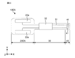
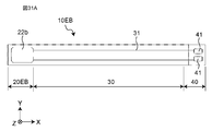
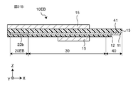
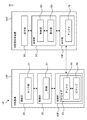
- FIG. 29A is a schematic cross-sectional view of an example of the oral appliance of FIG. 29A. It is a schematic diagram which shows the oral cavity device of the modification 12. It is a schematic diagram which shows the oral cavity device of the modification 13. It is the schematic sectional drawing of the oral cavity instrument of the modification 13 of FIG. 31A. It is a block diagram which shows the main structure of the example of the oral apparatus of Embodiment 6 which concerns on this invention.
- FIG. 3 is a schematic cross-sectional view of an example of the oral appliance of FIG. 33.
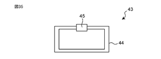
- It is a schematic diagram of an example of an RFID tag.
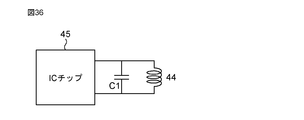
- It is a schematic circuit diagram of an example of an RFID tag.
- It is a schematic partial enlarged sectional view which shows the example of the attachment / detachment operation part enlarged.
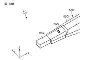
- It is a schematic perspective view of an example of the oral apparatus of Embodiment 7 which concerns on this invention.
- It is a schematic perspective view of an example of the oral apparatus of Embodiment 7 which concerns on this invention.
- It is a schematic plan view of an example of the oral cavity device of Embodiment 7 which concerns on this invention.
- It is the schematic sectional drawing of the oral cavity instrument of FIG.
- FIG. 39A cut along the line AA. It is a schematic diagram which shows an example of the operation of the attachment / detachment operation unit. It is a schematic diagram which shows an example of the operation of the attachment / detachment operation unit. It is a schematic diagram which shows an example of the operation of the attachment / detachment operation unit. It is a schematic sectional drawing of an example of the oral apparatus of Embodiment 8 which concerns on this invention. It is a schematic sectional drawing of an example of the oral apparatus of Embodiment 8 which concerns on this invention. It is a schematic bottom view of an example of the oral cavity device of Embodiment 8 which concerns on this invention. FIG. 42 is a schematic cross-sectional view taken along the line BB of the oral appliance of FIG.
- the moisture content detection unit (sensor unit) provided on the tip end side of the rocking member that swings with respect to the main body is brought into contact with the measurement site in the oral cavity, thereby causing the oral cavity. Moisture is being measured.
- the sensor portion and the swinging member are configured as a detachable portion that can be attached to and detached from the main body. This keeps the hygiene of the measuring instrument in a more appropriate condition. In such a device, the detachable portion is removed from the main body by pulling the tip end side of the detachable portion.
- the detachable part is the part that comes into contact with the measurement site in the oral cavity, saliva adheres after use. Therefore, when the user grasps and pulls the tip end side of the detachable portion when removing the detachable portion from the main body, saliva adheres to the user's hand.
- an oral main body device that can easily attach and detach an oral device in an oral main body device that can attach and detach an oral device that comes into contact with a measurement site in the oral cavity.
- an oral main body device that can remove a used oral device by operating the oral main body device without attaching saliva to the user's hand.
- the present inventors have found a configuration in which the oral device is attached and detached by manipulating the application and release of force to the oral device, and have reached the following invention.
- the oral main body device of one aspect of the present invention is It is a main body device for the oral cavity that can be attached and detached with an oral appliance that has an electrical connection.
- a detachable operation unit having an electrical connection conductor and configured to detachably attach the oral instrument to the main body portion by operating force application and release to the oral instrument. Equipped with The attachment / detachment operation unit fixes and attaches the oral cavity device in a state where the electrical connection portion and the electrical connection conductor are electrically connected by applying a force to the oral cavity device, and attaches the oral cavity device to the oral cavity device. By releasing the applied force, the fixation is released and the oral cavity device is removed.
- the oral appliance can be easily attached and detached.
- the attachment / detachment operation unit is The placement surface on which the oral device is placed and A pressing member that applies a force in a direction intersecting the arrangement surface, May have.
- the oral appliance can be attached and detached more easily.
- the holding member is It has one end provided on the arrangement surface side and the other end provided on the side opposite to the one end. It may be configured to be rotatable around a rotation axis arranged between the one end and the other end.
- the oral appliance can be attached and detached more easily.
- the holding member may have a protrusion protruding toward the arrangement surface between the one end and the rotating shaft.
- the holding member is It has a contact surface that comes into contact with the oral appliance and has a contact surface. It may be configured so as to be slidable in an oblique direction with respect to the arrangement surface.
- the oral appliance can be attached and detached more easily.
- the holding member is It has one end provided on the arrangement surface side and the other end provided on the side opposite to the one end.
- the contact surface By sliding from one end to the other end in the first oblique direction, the contact surface is brought into contact with the oral cavity device.
- the contact surface By sliding and moving in the second oblique direction opposite to the first oblique direction, the contact surface may be released from the contact with the oral instrument while pushing out the oral instrument.
- the oral appliance can be removed more easily.
- the pressing member may have a protrusion protruding from the contact surface toward the arrangement surface.
- the arrangement surface may be provided with a protrusion protruding toward the holding member.
- the arrangement surface is curved in a concave or convex shape.
- the holding member may be curved in a concave or convex shape along the shape of the arrangement surface.
- the oral appliance can be deformed and fixed.
- the oral main body device further A detection unit that detects whether or not the oral appliance is attached to the attachment / detachment operation unit, A control unit that determines whether or not the oral device can be used based on the detection result of the detection unit, Equipped with The control unit It is determined whether or not the oral appliance attached to the attachment / detachment operation unit has been used. When it is determined that the oral cavity device has been used, it is determined that the oral cavity device cannot be used, and after it is determined that the oral cavity device cannot be used, the used oral cavity is determined by the detection unit. When it is detected that the device has been removed and an unused oral device has been attached, it may be determined that the oral device can be used.
- the oral main body device further A display unit that displays information on whether or not the oral device can be used may be provided.
- the control unit determines that the oral appliance has been used, Stop using the oral device and Based on the determination that the oral device can be used, the oral device may be enabled.
- the main body is The grip part gripped by the user, A guard that protects the grip and May have.
- the electrical connection of the oral appliance is one or more electrodes.
- the electrical connection conductor of the oral body device is one or more connection terminals.
- the attachment / detachment operation unit may be electrically connected by physically contacting the one or more electrodes with the one or more connection terminals.
- the electrical connection of the oral appliance is an RFID tag.
- the electrical connection conductor of the oral main body device is a main body side antenna.
- the attachment / detachment operation unit may be electrically connected by wirelessly connecting the RFID tag and the main body side antenna.
- the oral main body device further A calculation unit that calculates the amount of water based on the information acquired by the oral appliance may be provided.
- the amount of water in the oral cavity can be measured.
- the electrical connection of the oral appliance has a plurality of electrodes.
- the electrical connection conductor has a plurality of connection terminals provided on both main surfaces of the substrate, and has a plurality of connection terminals.
- the attachment / detachment operation unit has a plurality of pressing members arranged on both main surfaces of the substrate and applying a force in a direction intersecting both main surfaces of the substrate.
- the plurality of pressing members may fix the oral cavity device by applying a force in a direction intersecting both main surfaces of the substrate in a state where the plurality of electrodes and the plurality of connection terminals are in contact with each other. good.
- the plurality of pressing members may each have protrusions protruding toward both main surfaces of the substrate.
- the oral appliance can be firmly fixed to the oral main body device.
- the electrical connection conductor is The connection terminals provided on one main surface of the board, Movable parts that move toward the connection terminal and come into contact with the connection terminal, Have, When the movable part comes into contact with the electrical connection portion of the oral appliance, it comes into contact with the connection terminal by moving toward the connection terminal.
- the attachment / detachment operation unit has a pressing member arranged on one main surface of the substrate and applying a force in a direction intersecting the one main surface of the substrate.
- the holding member may fix the oral cavity device by applying a force in a direction intersecting one main surface of the substrate in a state where the electrical connection portion, the movable component, and the connection terminal are in contact with each other.
- the electrical connection between the oral appliance and the main body device for the oral cavity can be easily and stably realized.
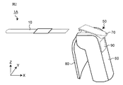
- FIG. 1 shows a state in which the oral appliance 10 is attached to the oral main body device 50.
- FIG. 2 shows a state in which the oral appliance 10 is removed from the oral main body device 50.
- the X, Y, and Z directions in the figure indicate the length direction, the width direction, and the height direction of the oral apparatus 1A, respectively.
- the oral device 1A includes an oral device 10 and an oral main body device 50.
- the oral device 1A is a disposable type device.
- the oral device 10 used in the oral cavity is detachably attached to the oral main body device 50.
- the oral device 10 is attached to the oral main body device 50 and used, and then removed from the oral main body device 50.
- the oral device 1A performs a function by bringing the oral device 10 into contact with a site in the oral cavity.
- Functions include, for example, a sensing function and / or an energy irradiation function.
- the sensing function acquires information related to biological information in the oral cavity.
- Biological information is various physiological and anatomical information emitted by a living body.
- Biological information includes, for example, dryness (wetness, water content), tongue pressure, bite force, masticatory function, swallowing function, tongue and lip movement function, poor hygiene, saliva component, exhaled gas component, body temperature, hardness, etc. Is.
- the information related to the biological information is, for example, information such as capacitance, impedance (resistance), pressure, potential, color tone, temperature, hardness, and vibration.
- the oral apparatus 1A brings the oral device 10 into contact with the measurement site in the user's oral cavity, and acquires information related to the biological information of the contacted measurement site.
- the oral device 1A measures the state in the oral cavity by acquiring biological information with the oral main body device 50 based on the information acquired by the oral device 10.
- the oral body device 50 measures, for example, the amount of water, the amount of saliva secreted, the bite force, the tongue pressure, the color tone of the tongue and / or the amount of various substances contained in saliva.
- the energy irradiation function irradiates the oral cavity with energy.
- Energy is energy such as light, heat, ultrasonic waves, and electromagnetic waves.
- the oral device 1A can be used as, for example, a wetness meter, an occlusal force meter, a tongue pressure gauge, a laser treatment device, a hyperthermia treatment device, an ultrasonic echo, an ultrasonic treatment device, and an electromagnetic wave irradiation device.
- the oral device 1A is a wetness meter
- FIG. 3 is a schematic view showing an example of a state in which the oral apparatus 1A according to the first embodiment of the present invention is used.
- the oral device 1A brings the oral device 10 into contact with the measurement site in the user's oral cavity.
- the measurement site is, for example, the tongue portion in the oral cavity, the buccal mucosa, the palate, and the like.
- the oral device 10 comes into contact with the measurement site by deforming along the shape of the measurement site.
- the oral device 1A starts the measurement in a state where the oral device 10 is in contact with the measurement site in the oral cavity.
- FIG. 4 is a schematic view showing an example of the oral appliance 10.
- FIG. 5 is a schematic cross-sectional view showing an enlarged example of the oral cavity device 10 of FIG.
- FIG. 6 is a block diagram showing the configuration of an example of the oral appliance 10.
- the oral cavity device 10 includes a functional unit 20, a wiring unit 30, and a connection unit 40.
- the oral appliance 10 is configured as a sensing probe that can be attached to and detached from the oral main body device 50.
- the oral device 10 is a sheet-shaped device having an electrical connection portion.
- the oral appliance 10 is formed in the shape of a rectangular sheet having a longitudinal direction. Further, the oral appliance 10 has flexibility and can be deformed.
- the electrical connection part is electrically connected to the oral main body device 50.
- the electrical connection is one or more electrodes 41.
- the functional unit 20 is a portion that exerts a sensing function, and is provided on the tip end side of the oral cavity device 10.
- the functional unit 20 has a sensor unit 21 that acquires information in the oral cavity.
- the sensor unit 21 has a sensor surface 21a arranged on the measurement site side in the oral cavity of the user.
- the functional unit 20 acquires information in the oral cavity by bringing the sensor surface 21a side of the sensor unit 21 into surface contact with the measurement site.
- the sensor unit 21 has a capacitance sensor and acquires the capacitance.
- the wiring unit 30 is arranged between the functional unit 20 and the connection unit 40.
- the wiring unit 30 has a wiring 31 that electrically connects the functional unit 20 and the electrode 41 of the connection unit 40.
- the wiring 31 is made of a conductive material.
- the wiring 31 is formed of a wiring conductor pattern.
- the thickness of the wiring layer 11 is preferably 1 ⁇ m or more and 50 ⁇ m or less. More preferably, the thickness of the wiring layer 11 is 2 ⁇ m or more and 25 ⁇ m or less.
- the wiring portion 30 has a protective layer 32 that covers the periphery of the wiring portion 30.
- the protective layer 32 is arranged at a portion where the teeth come into contact when the oral appliance 10 is placed in the oral cavity.
- the protective layer 32 may be arranged between the functional portion 20 and the connecting portion 40.
- the protective layer 32 is formed of a protective film having a thickness of 100 ⁇ m or more and 10 mm or less.
- the protective film may be made of a material such as a resin or a foam.
- connection portion 40 is a portion attached to the oral main body device 50, and is provided on the rear end side opposite to the front end of the oral cavity device 10.
- the connection portion 40 has one or more electrodes 41.
- the connection portion 40 has two electrodes 41.
- the number of electrodes 41 is not limited to two.
- the one or more electrodes 41 are made of a conductive material.
- connection portion 40 when the connection portion 40 is attached to the oral main body device 50, a plurality of electrodes 41 are electrically connected by physically contacting a plurality of connection terminals provided in the oral main body device 50. Will be done.
- connection portion 40 is provided with a mounting hole 42.
- the mounting hole 42 is a through hole into which the protrusion 73a of the attachment / detachment operation portion 70, which will be described later, is inserted.
- two mounting holes 42 are provided in the connecting portion 40.
- the mounting hole 42 is not limited to the through hole, but may be a notch or a recess.
- the mounting hole 42 may have a size into which the protrusion 73a of the attachment / detachment operation portion 70 can be inserted.
- the connection portion 40 may be provided with one or a plurality of mounting holes 42.
- the oral cavity device 10 is formed of a wiring layer 11 and a plurality of insulating layers 12 and 13.
- the wiring layer 11 and the plurality of insulating layers 12 and 13 are laminated.
- the wiring layer 11 includes a sensor unit 21, a wiring 31, and a plurality of electrodes 41.
- the wiring layer 11 has a first main surface PS1 and a second main surface PS2 on the opposite side of the first main surface PS1.
- the PS1 side of the first main surface is the side that comes into contact with the measurement site in the oral cavity.
- the sensor surface 21a of the sensor unit 21 is arranged on the first main surface PS1 side of the wiring layer 11.
- the plurality of electrodes 41 are exposed from the insulating layer 12.
- the plurality of insulating layers 12 and 13 include a first insulating layer 12 arranged on the first main surface PS1 of the wiring layer 11 and a second insulating layer 13 arranged on the second main surface PS2 of the wiring layer 11. Have.
- the thickness T1 of the first insulating layer 12 is smaller than the thickness T2 of the second insulating layer 13.
- the thickness T1 of the first insulating layer 12 is preferably 25 ⁇ m or less.
- the thickness T2 of the second insulating layer 13 is preferably 10 ⁇ m or more and 200 ⁇ m or less.
- the wiring layer 11 and the plurality of insulating layers 12 and 13 are formed of a flexible printed circuit board.
- the above-mentioned oral device 10 is an example, and the configuration of the oral device 10 is not limited to this.
- the oral device 10 may be any device having an electrical connection portion.
- the shape of the oral appliance 10C is not limited to the sheet shape.
- the oral appliance 10 may have a shield layer in addition to the wiring layer 11 and the plurality of insulating layers 12 and 13.
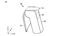
- FIG. 7 is a schematic perspective view of an example of the oral main body device 50.
- FIG. 8 is a schematic exploded view of an example of the oral main body device 50 of FIG.
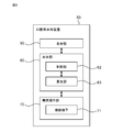
- FIG. 9 is a block diagram showing the configuration of an example of the oral main body device 50.
- the oral main body device 50 may be referred to as a main body device 50.
- the main body device 50 includes a main body unit 60, a detachable operation unit 70, a guard 80, and a display unit 90.
- a main body unit 60 the main body device 50 includes a guard 80 and a display unit 90
- the guard 80 and the display unit 90 are not essential configurations.
- the display unit 90 may be provided in a device other than the main body device 50.
- the main body device 50 can detachably attach the oral appliance 10 to the attachment / detachment operation unit 70. Further, the main body device 50 calculates the amount of the object to be measured based on the information related to the biological information acquired by the oral appliance 10. Specifically, the main body device 50 calculates the water content (wetness) based on the capacitance acquired by the oral appliance 10.
- the main body portion 60 is a main body portion of the main body device 50.
- the main body 60 is formed of a rod-shaped member having a longitudinal direction.
- the main body 60 has a grip 61 that is gripped by the user.
- the grip portion 61 is formed by the appearance shape of the main body portion 60.
- a detachable operation unit 70 is arranged on one end side of the main body unit 60.
- a guard 80 and a display unit 90 are arranged on the main body unit 60.
- the main body unit 60 includes a control unit 62 and a calculation unit 63.
- the control unit 62 comprehensively controls the components constituting the oral apparatus 1A.
- the control unit 62 includes, for example, a memory for storing a program and a processing circuit corresponding to a processor such as a CPU (Central Processing Unit).
- a processor such as a CPU (Central Processing Unit).
- the processor executes a program stored in the memory.
- the control unit 62 controls the calculation unit 63 and the display unit 90.
- the calculation unit 63 calculates the amount of the object to be measured based on the information acquired by the oral appliance 10. In the first embodiment, the calculation unit 63 calculates the water content based on the capacitance acquired by the oral appliance 10.
- the calculation unit 63 can be realized by a semiconductor element or the like.
- the function of the calculation unit 63 may be configured only by hardware, or may be realized by combining hardware and software.
- the calculation unit 63 has a water content calculation circuit.
- the water content calculation circuit calculates the water content from the capacitance acquired by the oral appliance 10 based on the relational expression between the capacitance and the water content.
- the water content information calculated by the calculation unit 63 is transmitted to the display unit 90.
- the attachment / detachment operation unit 70 is configured to attach / detach the oral appliance 10 to the main body 60 by operating the application and release of the force to the oral appliance 10.
- the attachment / detachment operation unit 70 is configured to detachably attach the oral device 10 in a direction intersecting the extending direction of the main body unit 60. That is, the attachment / detachment direction of the oral appliance 10 is a direction that intersects with the extending direction of the main body 60.
- the attachment / detachment operation unit 70 has an electrical connection conductor.
- the electrical connection conductor is a conductor that is electrically connected to the oral cavity device 10. Specifically, the electrical connection conductor is electrically connected to the electrical connection portion of the oral appliance 10.
- the electrical connection conductor is one or more connection terminals 71.
- the one or more connection terminals 71 are made of a conductive material.
- the one or more connection terminals 71 are electrically connected by physical contact with one or more electrodes 41 provided in the connection portion 40 of the oral appliance 10.
- the attachment / detachment operation unit 70 fixes and attaches the oral appliance 10 in a state where the electrode 41 and the connection terminal 71 are electrically connected by applying a force to the connection portion 40 of the oral appliance 10. Further, the attachment / detachment operation unit 70 releases the force applied to the connection portion 40 of the oral appliance 10 to release the fixation and remove the oral appliance 10. Further, when the oral appliance 10 is removed, the electrical connection between the electrode 41 and the connection terminal 71 may be disconnected.
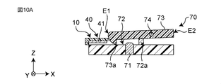
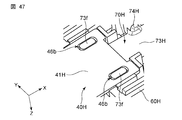
- the attachment / detachment operation unit 70 has an arrangement surface 72 on which the oral cavity device 10 is arranged, and a pressing member 73 for applying a force in a direction intersecting the arrangement surface 72.
- the pressing member 73 is arranged above the arrangement surface 72.
- the arrangement surface 72 is provided on the end surface on one end side of the main body 60.
- the arrangement surface 72 is a surface on which the oral device 10 can slide and move.
- the arrangement surface 72 may be formed by recessing the end surface on one end side of the main body 60, or may be formed by a flat surface.
- connection terminals 71 are arranged on the arrangement surface 72.
- the one or more connection terminals 71 are arranged at positions corresponding to the one or more electrodes 41 when the oral appliance 10 is arranged and fixed on the arrangement surface 72.
- two connection terminals 71 are arranged on the arrangement surface 72.
- the number of connection terminals 71 is not limited to two.
- the arrangement surface 72 is provided with a positioning member 72a extending toward the pressing member 73.
- the positioning member 72a determines the position in the X direction on the arrangement surface 72.
- the positioning member 72a may be formed, for example, by a step formed on the arrangement surface 72, or may be formed so as to project convexly from the arrangement surface 72 toward the pressing member 73. For example, when the oral device 10 is slid and moved in the X direction and placed on the arrangement surface 72, the oral device 10 is slid and moved until the end portion of the connecting portion 40 of the oral device 10 comes into contact with the positioning member 72a.
- the position of the oral device 10 in the X direction can be easily determined by sliding the oral device 10 until it comes into contact with the positioning member 72a. ..
- the electrode 41 of the oral cavity device 10 and the connection terminal 71 arranged on the arrangement surface 72 can be easily attached at a position where they physically come into contact with each other, and electrical connection can be easily performed.
- the pressing member 73 is a member capable of operating the application and release of a force to the oral appliance 10.
- the pressing member 73 is configured to apply a force in a direction intersecting the arrangement surface 72.
- the holding member 73 can fix the oral cavity device 10 to the arrangement surface 72 in a state where the electrode 41 and the connection terminal 71 are electrically connected.
- the pressing member 73 is formed of a plate-shaped member having one end E1 and the other end E2. One end E1 is provided on the arrangement surface 72 side. The other end E2 is provided on the side opposite to the one end E1.
- a rotation shaft 74 is arranged between one end E1 and the other end E2 of the pressing member 73.
- the pressing member 73 is configured to be rotatable around a rotating shaft 74. Further, one end E1 of the pressing member 73 is urged by an elastic body in a direction approaching the arrangement surface 72, for example. Examples of the elastic body include springs and rubber.
- the pressing member 73 has a protrusion 73a that projects toward the arrangement surface 72 between one end E1 and the rotating shaft 74.
- the protrusion 73a is inserted into a mounting hole 42 provided in the connection portion 40 of the oral appliance 10.
- the pressing member 73 has two protrusions 73a provided on one end E1 of the pressing member 73.
- the pressing member 73 may have one or a plurality of protrusions 73a.
- the attachment / detachment operation unit 70 operates the rotation operation of the pressing member 73 to apply and release the force to the oral cavity device 10. Specifically, when the pressing member 73 is not operated, one end E1 of the pressing member 73 moves in a direction approaching the arrangement surface 72 due to the urging force of the elastic body, and the oral appliance 10 arranged on the arrangement surface 72. Press against. As a result, the oral device 10 can be fixed so as to be sandwiched between the arrangement surface 72 and the pressing member 73, and the oral device 10 can be attached to the attachment / detachment operation unit 70. Further, by inserting the protrusion 73a of the pressing member 73 into the mounting hole 42 of the connecting portion 40, the oral cavity device 10 can be fixed so as not to come off from the attachment / detachment operation portion 70.
- the oral appliance 10 When the oral appliance 10 is removed from the attachment / detachment operation unit 70, the other end E2 of the pressing member 73 is pushed down so that one end E1 of the pressing member 73 moves away from the arrangement surface 72. As a result, the pressing force applied to the oral device 10 by the pressing member 73 can be released, and the oral device 10 can be removed from the attachment / detachment operation unit 70. In this way, since the oral device 10 can be removed by operating the attachment / detachment operation unit 70, the oral device 10 can be easily removed without touching the used oral device 10.
- the pressing member 73 may apply a force in a direction in which the pressing member 73 intersects the arrangement surface 72 by a mechanism other than the elastic body, for example, a lock mechanism, a slide mechanism, and / or an electromagnetic force. Further, a suction portion may be provided and a force may be applied to the oral appliance 10 by the suction force.
- the guard 80 is arranged in the main body 60 and protects the grip 61.
- the guard 80 prevents saliva from adhering to the user's hand holding the grip portion 61 when the user uses the oral device 1A.
- the guard 80 is arranged on the main body 60 on the side to which the oral appliance 10 is attached.
- the side on which the oral device 10 is attached means the side on which the oral device 10 is attached and detached.
- the guard 80 is formed of a plate-shaped member.
- the display unit 90 is arranged on the main body unit 60 and displays information on the oral apparatus 1A.
- the information of the oral apparatus 1A includes, for example, information to be measured.
- the information to be measured is the water content information.
- the calculation unit 63 calculates the water content based on the capacitance acquired by the oral appliance 10.
- the calculation unit 63 transmits information on the amount of water to the display unit 90.
- the display unit 90 is, for example, a display.
- the main unit device 50 may include an input unit for inputting input information from the user.
- the input unit may have one or more buttons for receiving input from the user.
- the one or more buttons may include, for example, a power button for switching power ON / OFF, a measurement start button for starting measurement, and the like.
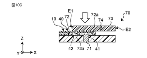
- FIGS. 10A-10C and 11 are schematic views showing an example of the operation of the attachment / detachment operation unit 70.
- 10A-10C show an example of the operation of attaching the oral appliance 10.
- FIG. 11 shows an example of an operation of removing the oral appliance 10.
- one end E1 of the pressing member 73 is pressed against the arrangement surface 72 by the urging force of the elastic body before the oral appliance 10 is attached.
- the other end E2 of the pressing member 73 is in a state of being lifted upward.
- the connecting portion 40 of the oral cavity device 10 is slid and moved on the arrangement surface 72 and inserted into the attachment / detachment operation portion 70. Specifically, the oral appliance 10 is slid to move until the end of the connecting portion 40 comes into contact with the positioning member 72a.
- the connection portion 40 of the oral appliance 10 is positioned at a position where the electrode 41 and the connection terminal 71 are in physical contact with each other. As a result, the electrode 41 and the connection terminal 71 are electrically connected.
- connection portion 40 of the oral cavity device 10 As shown in FIG. 10C, with the connection portion 40 of the oral cavity device 10 arranged on the arrangement surface 72, the force applied to the other end E2 of the holding member 73 is released. As a result, one end E1 of the pressing member 73 moves toward the arrangement surface 72 and presses the connecting portion 40 of the oral cavity device 10. The connection portion 40 of the oral appliance 10 is sandwiched and fixed between the arrangement surface 72 and the pressing member 73.
- the protrusion 73a provided at one end E1 of the holding member 73 is inserted into the mounting hole 42 of the connection portion 40 of the oral appliance 10. As a result, it is possible to prevent the oral appliance 10 from falling out of the attachment / detachment operation unit 70.
- the attachment / detachment operation unit 70 attaches the oral appliance 10 to the main body device 50 in a state where the electrode 41 and the connection terminal 71 are electrically connected by applying the pressing force of the pressing member 73 to the oral appliance 10. It is fixed and attached.
- the attachment / detachment operation unit 70 releases the fixation by releasing the pressing force applied to the oral appliance 10 by the pressing member 73, and removes the oral appliance 10 from the main body device 50.
- the oral main body device 50 can be attached to and detached from the oral device 10 having an electrical connection portion.
- the oral main body device 50 includes a main body 60 and a detachable operation unit 70.
- the attachment / detachment operation unit 70 has an electrical connection conductor, and is configured to detachably attach the oral appliance 10 to the main body 60 by operating the application and release of a force to the oral appliance 10.
- the attachment / detachment operation unit 70 fixes and attaches the oral appliance 10 in a state where the electrical connection portion and the electrical connection conductor are electrically connected by applying a force to the oral appliance 10. Further, the attachment / detachment operation unit 70 releases the fixation by releasing the force applied to the oral appliance 10, and removes the oral appliance 10.
- the oral device 10 can be easily attached and detached.
- the oral main body device 50 can easily attach and detach the oral appliance 10 by operating the attachment / detachment operation unit 70.
- the user can release the force fixing the oral device 10 by operating the attachment / detachment operation unit 70, and can remove the oral device 10 from the main body device 50. That is, the user can easily remove the oral device 10 without touching the oral device 10. As a result, the user can remove the oral device 10 from the main body device 50 without touching the used oral device 10 to which saliva or the like is attached.
- the electrical connection portion of the oral device 10 and the electrical connection conductor of the main body device 50 can be easily and electrically connected. Further, the attachment of the oral device 10 to the main body device 50 and the electrical connection between the oral device 10 and the main body device 50 can be realized by one mechanism. As a result, the number of parts constituting the main body device 50 can be reduced, and the device cost can be reduced.
- the oral appliance 10 used in the oral cavity By configuring the oral appliance 10 used in the oral cavity to be detachable from the main body device 50, it can be used without using a cover or the like. As a result, when the oral device 10 is used for the purpose of sensing, the oral device 10 can be brought into direct contact with the measurement site in the oral cavity, so that the measurement accuracy can be improved.
- the attachment / detachment operation unit 70 has an arrangement surface 72 on which the oral cavity device 10 is arranged, and a pressing member 73 for applying a force in a direction intersecting the arrangement surface 72.
- the attachment / detachment operation unit 70 can press the oral cavity device 10 arranged on the arrangement surface 72 by the pressing member 73, and fix the oral cavity device 10 to the main body device 50 for attachment.
- the oral appliance 10 can be firmly removed from the main body device 50 by releasing the pressing pressure by the pressing member 73. In this way, the oral device 10 can be easily attached and detached by applying and releasing the pressing force of the pressing member 73 to the oral device 10 arranged on the arrangement surface 72.
- the pressing member 73 has one end E1 provided on the arrangement surface 72 side and the other end E2 provided on the side opposite to one end E1, and the rotary shaft 74 arranged between one end E1 and the other end E2. It is configured to be rotatable around. With such a configuration, the pressing force can be easily applied and released by the pressing member 73. That is, the operability of the attachment / detachment operation unit 70 is improved. As a result, the oral device 10 can be attached and detached more easily.
- the pressing member 73 has a protrusion 73a that projects toward the arrangement surface 72 between one end E1 and the rotating shaft 74. With such a configuration, it is possible to prevent the oral appliance 10 from coming out of the attachment / detachment operation unit 70. For example, by inserting the protrusion 73a into the mounting hole 42 provided in the oral device 10, it is possible to prevent the oral device 10 from moving in the removal direction. Thereby, the oral device 10 can be fixed more firmly.
- the main body 60 has a grip 61 gripped by the user and a guard 80 that protects the grip 61.
- the guard 80 can protect saliva and the like from adhering to the hand of the user holding the grip portion 61.
- the electrical connection of the oral appliance 10 is one or more electrodes 41.
- the electrical connection conductor of the oral main body device 50 is one or a plurality of connection terminals 71.
- the attachment / detachment operation unit 70 is electrically connected by physically contacting one or more electrodes 41 with one or more connection terminals 71. With such a configuration, the oral device 10 and the main body device 50 can be easily electrically connected.
- the oral main body device 50 includes a calculation unit 63 that calculates the water content based on the information acquired by the oral appliance 10. With such a configuration, the amount of water in the oral cavity can be measured.
- the oral apparatus 1A is an oral moisturizer for measuring the amount of water in the oral cavity
- the oral device 1A may be any device as long as it is a device for acquiring information in the oral cavity and / or a device for irradiating the oral cavity with energy.
- the sensor unit 21 of the oral appliance 10 has a capacitance sensor
- the present invention is not limited to this.
- the sensor unit 21 may have a sensor capable of acquiring biometric information.
- the sensor unit 21 has at least one of an impedance measurement sensor, a resistance sensor, a load sensor, a humidity sensor, a pressure sensor, a color sensor, a temperature sensor, a hardness sensor, a vibration sensor, a biosensor, and the like. Just do it.
- calculation unit 63 calculates the water content from the capacitance
- the calculation unit 63 may be able to calculate the information in the oral cavity based on the information acquired by the oral appliance 10.
- the attachment / detachment operation unit 70 is configured so that the oral cavity device 10 is detachably attached in a direction intersecting the extending direction of the main body portion 60
- the present invention is not limited to this.
- the attachment / detachment operation unit 70 may be configured to detachably attach the oral appliance 10 in parallel with the extending direction of the main body unit 60.
- the attachment / detachment operation unit 70 has the positioning member 72a, but the present invention is not limited to this.
- the attachment / detachment operation unit 70 may not have the positioning member 72a.
- connection terminal 71 is arranged on the arrangement surface 72
- the present invention is not limited to this.
- the connection terminal 71 may be arranged on the holding member 73.
- the oral cavity device 10 may be attached or detached by the pressing force and / or the electromagnetic force of the pressing member 73.
- the electrode 41 of the oral appliance 10 may be made of a metal that reacts with a magnet.
- the metal that reacts with the magnet is, for example, iron, cobalt, nickel, or the like.
- the main body device 50 may be provided with a magnet. The electrode 41 of the oral appliance 10 may be attracted to the arrangement surface 72 by the magnetic force of the magnet provided in the main body device 50.
- the pressing member 73 may have a configuration capable of applying and releasing a force to the oral appliance 10 arranged on the arrangement surface 72.
- the pressing member 73 has a protrusion 73a
- the present invention is not limited to this.
- the pressing member 73 may not have the protrusion 73a.
- the protrusion 73a is provided at one end E1 of the pressing member 73
- the present invention is not limited to this.
- the protrusion 73a may be provided at a position where it is inserted into the mounting hole 42 of the oral appliance 10.
- the electrical connection portion of the oral appliance 10 is the electrode 41 and the electrical connection conductor of the main body device 50 is the connection terminal 71 has been described, but the present invention is not limited to this.
- the "state in which the electrical connection portion and the electrical connection conductor are electrically connected” is not limited to the state in which the electrical connection portion and the electrical connection conductor are physically in contact with each other.
- the "state in which the electrical connection portion and the electrical connection conductor are electrically connected” may include a state in which the electrical connection portion and the electrical connection conductor are electrically connected in a non-contact manner.
- an electrical connection may be realized by wirelessly connecting an electrical connection unit and an electrical connection conductor using a wireless communication device such as an RFID tag.
- FIG. 12 is a schematic view showing the attachment / detachment operation unit 70A of the modification 1.
- the protrusion 73b may be arranged between one end E1 of the pressing member 73 and the rotating shaft 74. Even in such a configuration, the oral appliance 10 can be fixed more firmly.
- FIG. 13A is a schematic view showing the holding member 73A of the modified example 2.
- FIG. 13B is a schematic view showing the oral appliance 10A of the modified example 2.
- the two protrusions 73a are arranged asymmetrically with respect to the center line extending in the X direction.
- the two mounting holes 42 in the connecting portion 40A are arranged asymmetrically with respect to the center line extending in the X direction.
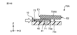
- (Modification 3) 14A and 14B are schematic views showing the operation of the attachment / detachment operation unit 70A of the modification 3.
- 14C-14E is a schematic perspective view showing the operation of the attachment / detachment operation unit 70A of the modification 3.
- 14A-14E show an example of the attachment operation of the oral appliance 10.
- the attachment / detachment operation unit 70A is configured so that the pressing member 73AA can be slidably moved.
- the pressing member 73AA is formed of a plate-shaped member having one end E1 provided on the arrangement surface 72 side and the other end E2 provided on the side opposite to one end E1.
- the pressing member 73AA has a contact surface 73c that comes into contact with the oral appliance 10.
- the contact surface 73c is a flat surface provided on the arrangement surface 72 side.
- the pressing member 73AA is configured to be slidable in an oblique direction with respect to the arrangement surface 72.
- the attachment / detachment operation unit 70A has a slide mechanism for sliding the pressing member 73AA in an oblique direction with respect to the arrangement surface 72.
- the pressing member 73AA is inclined with respect to the arrangement surface 72, for example, in a range of 2 ° or more and 20 ° or less. Further, the pressing member 73AA is tilted in a state where one end E1 is lifted from the other end E2 with respect to the main body 60.
- FIG. 14A the holding member 73AA slides and moves in the first diagonal direction D1 from one end E1 to the other end E2 in a state where the oral cavity device 10 is arranged on the arrangement surface 72.
- the pressing member 73AA comes into contact with the oral appliance 10.
- the contact surface 73c of the pressing member 73A comes into contact with the connecting portion 40 of the oral appliance 10. Friction force is generated by the contact between the contact surface 73c of the pressing member 73A and the connecting portion 40 of the oral cavity device 10.
- the pressing member 73AA slides in the first diagonal direction D1 and the contact surface 73c and the connecting portion 40 of the oral appliance 10 come into contact with each other, so that the pressing member 73AA rubs in the direction opposite to the direction in which the oral appliance 10 is removed. Force is generated. By this frictional force, the oral cavity device 10 can be pulled in and fixed to the other end E2 side of the pressing member 73AA. As a result, the oral appliance 10 can be fixed to the main body 60.
- the attachment / detachment operation unit 70A is provided with a slide groove 73d into which both ends of the pressing member 73AA are inserted as a slide mechanism.
- the slide groove 73d is a concave groove extending in the X direction of the main body device 50.
- the width of the slide groove 73d becomes smaller toward the attachment direction of the oral cavity device 10, that is, the insertion direction (X direction).
- the width of the slide groove 73d is the length in the Z direction in FIGS. 14C to 14E.
- the upper side of the slide groove 73d extends diagonally with respect to the arrangement surface 72, while the lower side of the slide groove 73d extends parallel to the arrangement surface 72.
- the width of the pressing member 73AA on the left end side of the slide groove 73d is larger than the thickness of the pressing member 73AA. Therefore, when the pressing member 73AA is located on the left end side of the slide groove 73d, the pressing member 73AA can move in the vertical direction (Z direction).
- the oral cavity device 10 is inserted along the arrangement surface 72 of the attachment / detachment operation unit 70A.
- the pressing member 73AA is located on the left end side of the slide groove 73d.
- the holding member 73AA is pushed upward by arranging the oral appliance 10 on the arrangement surface 72.
- the pressing member 73AA is slid and moved in the first diagonal direction D1. Specifically, the pressing member 73AA is moved from the left end to the right end of the slide groove 73d.
- the pressing member 73AA slides and moves along the upper side of the slide groove 73d.
- the upper side of the slide groove 73d extends diagonally with respect to the arrangement surface 72.
- the pressing member 73AA slides and moves toward the first diagonal direction D1, which is an oblique direction with respect to the arrangement surface 72.
- the holding member 73AA is arranged at the right end of the slide groove 73d to fix the oral appliance 10.
- 15A-15B show an example of the removal operation of the oral appliance 10.
- the pressing member 73AA slides and moves in the second diagonal direction D2 opposite to the first diagonal direction D1.
- the second diagonal direction D2 is a direction from the other end E2 of the pressing member 73AA toward one end E1.
- the oral appliance 10 is pushed out in the removal direction, and the contact surface 73c of the pressing member 73AA and the connecting portion 40 of the oral appliance 10 are connected to each other. Release the contact.
- the oral device 10 can be released from the fixation and the oral device 10 can be easily removed. Further, since the oral device 10 can be pushed out in the removal direction by the pressing member 73AA, the user can remove the oral device 10 by operating the attachment / detachment operation unit 70A without touching the oral device 10.
- the pressing member 73AA may have a protrusion protruding from the contact surface 73c toward the arrangement surface 72.
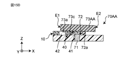
- 15C and 15D are schematic views showing the operation of another attachment / detachment operation unit of the modified example 3.
- the pressing member 73AA may have a protrusion 73a protruding from the contact surface 73c toward the arrangement surface 72.
- the protrusion 73a may be inserted into the mounting hole 42 of the oral appliance 10. Thereby, the oral device 10 can be fixed more firmly.
- FIG. 15E is a schematic view showing the attachment / detachment operation unit 70AB of the modified example 4.
- the protrusion 73a may be provided on the arrangement surface 72.
- the attachment / detachment operation unit 70AB has the same configuration as the attachment / detachment operation unit 70 of the first embodiment except for the position of the protrusion 73a. Even in such a configuration, it is possible to prevent the oral appliance 10 from moving in the removal direction. Thereby, the oral device 10 can be fixed more firmly.
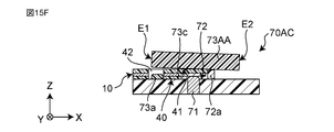
- FIG. 15F is a schematic view showing the attachment / detachment operation unit 70AC of the modification 5.
- the protrusion 73a may be provided on the arrangement surface 72 in the attachment / detachment operation unit 70AC.
- the attachment / detachment operation unit 70AC has the same configuration as another attachment / detachment operation unit 70AA of the modification 3 except for the position of the protrusion 73a. Even in such a configuration, it is possible to prevent the oral appliance 10 from moving in the removal direction. Thereby, the oral device 10 can be fixed more firmly.
- FIG. 16 is a block diagram showing a main configuration of an example of the oral apparatus 1B according to the second embodiment of the present invention.
- the second embodiment is different from the first embodiment in that the oral main body device 50B includes a detection unit 75.
- the attachment / detachment operation unit 70B of the oral main body device 50B includes a detection unit 75.
- the detection unit 75 detects whether or not the oral appliance 10 is attached to the attachment / detachment operation unit 70B. The detection by the detection unit 75 will be described later. Information on the detection result of the detection unit 75 is transmitted to the control unit 62.
- the control unit 62 determines whether or not to use the oral device 10 based on the detection result of the detection unit 75. Specifically, the control unit 62 stops using the oral device 10 after the oral device 10 is used in a state of being attached to the attachment / detachment operation unit 70B. When the detection unit 75 detects that the used oral device 10 has been removed and the unused oral device 10 has been attached, the control unit 62 enables the use of the unused oral device 10. Further, the control unit 62 transmits information on whether or not the oral device 10 can be used to the display unit 90.
- Stopping the use of the oral appliance 10 includes, for example, disabling the operation of the main body device 50B.
- the control unit 62 determines whether or not the oral device 10 attached to the attachment / detachment operation unit 70B has been used. In particular. The control unit 62 determines whether the oral device 10 is used or unused based on the information acquired by the oral device 10. For example, the control unit 62 may determine whether or not the oral device 10 has been used based on the information on whether or not the water content calculation process has been performed by the calculation unit 63. After performing the calculation process, the calculation unit 63 transmits the calculation process completion flag information to the control unit 62. When the control unit 62 receives the calculation process completion flag information, the control unit 62 determines that the oral appliance 10 has been used. The determination of whether the oral appliance 10 is used or unused is not limited to this. The determination of whether the oral appliance 10 is used or unused may be made based on other information.
- control unit 62 determines that the oral device 10 has been used, the control unit 62 stops using the oral device 10. Further, the control unit 62 transmits information indicating that the use of the oral device 10 is stopped to the display unit 90.
- control unit 62 After stopping the use of the oral device 10, when the control unit 62 detects that the used oral device 10 has been removed and the unused oral device 10 has been attached by the detection unit 75, the control unit 62 is unused. Allows the use of the oral appliance 10.
- control unit 62 When the control unit 62 detects that the used oral device 10 has been removed by the detection unit 75, the control unit 62 clears the calculation process completion flag information. As a result, the main body device 50B waits until the unused oral device 10 is attached to the attachment / detachment operation unit 70B.
- control unit 62 When the control unit 62 detects that the unused oral device 10 is attached to the attachment / detachment operation unit 70B by the detection unit 75, the control unit 62 enables the use of the oral device 10. Further, the control unit 62 transmits information indicating that the oral device 10 can be used to the display unit 90.
- the display unit 90 displays information on whether or not the oral device 10 can be used.
- the information on whether or not the oral device can be used includes information indicating that the use of the oral device 10 has been stopped and information indicating that the oral device 10 can be used.
- the information indicating that the oral device 10 has been stopped may be a message prompting the replacement of the used oral device 10.
- the information indicating that the oral device 10 can be used may be to stop displaying the message.
- the control unit 62 does not have to stop using the oral appliance 10.
- the control unit 62 may determine whether or not the oral device 10 can be used without stopping the use of the oral device 10, and may cause the display unit 90 to display information on the determination result of whether or not the oral device 10 can be used. For example, when the control unit 62 determines that the oral device 10 has been used, the control unit 62 may display the exchange message on the display unit 90 without stopping the use of the oral device 10.
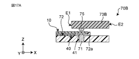
- the detection unit 75 will be described with reference to FIGS. 17A-17C.
- 17A-17C is a schematic diagram showing an example of the operation of the detection unit.
- the detection unit 75 is composed of a switch.
- the detection unit 75 is a push-type switch. The push-type switch turns on when the switch is pressed and turns off when the switch is not pressed.
- the detection unit 75 is arranged on the pressing member 73B. Specifically, the detection unit 75 is arranged on the side of the arrangement surface 72 of the pressing member 73B. Further, the detection unit 75 is arranged on one end E1 side of the pressing member 73B. The detection unit 75 is arranged at a position where it physically contacts the connection portion 40 of the oral cavity device 10 arranged on the arrangement surface 72.
- the detection unit 75 physically contacts the oral appliance 10. As a result, the switch of the detection unit 75 is turned on. The detection unit 75 detects that the oral cavity device 10 is attached to the attachment / detachment operation unit 70B when the switch is turned on.
- the detection unit 75 when the oral appliance 10 is not arranged on the arrangement surface 72, the detection unit 75 does not physically contact the oral appliance 10 even if the pressing member 73B is pressed toward the arrangement surface 72. Therefore, the switch of the detection unit 75 remains OFF. The detection unit 75 detects that the oral cavity device 10 is removed from the attachment / detachment operation unit 70B when the switch is OFF.
- the oral main body device 50B includes a detection unit 75 that detects whether or not the oral device 10 is attached to the attachment / detachment operation unit 70B.
- the control unit 62 determines whether or not the oral device 10 can be used based on the detection result of the detection unit 75.
- the control unit 62 determines whether or not the oral device 10 attached to the attachment / detachment operation unit 70B has been used.
- the control unit 62 determines that the oral device 10 cannot be used.
- the control unit 62 detects that the used oral device 10 has been removed and that the unused oral device 10 has been attached by the detection unit 75. At that time, it is determined that the oral appliance 10 can be used.
- the display unit 90 displays information on whether or not the oral device 10 can be used. With such a configuration, the user can easily know whether or not the oral appliance 10 has been used.
- the control unit 62 stops using the oral device 10.
- the control unit 62 enables the use of the oral device 10 based on the determination that the oral device 10 can be used. With such a configuration, it is possible to prevent the user from using the used oral device 10 again.
- the display unit 90 displays information on whether or not the oral device 10 can be used in the main body device 50B
- the present invention is not limited to this.
- the display unit 90 displays information on whether or not the oral device 10 can be used.
- the display unit 90 displays a message prompting the replacement of the used oral device 10
- the present invention is not limited to this.
- the display unit 90 may display a message indicating that it has been used or has not been used.
- the display unit 90 may indicate information by light, color, sound, or the like.
- the detection unit 75 may have a configuration capable of detecting whether or not the oral appliance 10 is attached to the attachment / detachment operation unit 70B.
- the detection unit 75 may be a sensor such as a capacitance sensor. In this case, the detection unit 75 may detect the attachment / detachment of the oral cavity device 10 based on the change in capacitance.
- the detection unit 75 may detect whether or not the oral device 10 is attached to the attachment / detachment operation unit 70B based on the information acquired by the oral device 10. For example, the detection unit 75 may detect whether or not the oral device 10 is attached to the attachment / detachment operation unit 70B based on the capacitance and the threshold value acquired by the oral device. In this case, the detection unit 75 may be included in the calculation unit 63. With such a configuration, the number of mechanical components for detection can be reduced, and the cost can be reduced.
- the detection unit 75 may be arranged at a position where it can detect the attachment / detachment of the oral device 10.
- the detection unit 75 may be arranged on the arrangement surface 72.
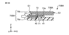
- FIGS. 18A and 18B are schematic views showing the operation of the detection unit 75BA of the modification 6.
- the detection unit 75BA may be composed of a photo sensor.
- the detection unit 75B includes a light emitting unit 76a that emits light and a light receiving unit 76b that receives light.
- the light emitting unit 76a is arranged on the arrangement surface 72. Specifically, the light emitting unit 76a is arranged in a hole provided in the arrangement surface 72. The light emitting unit 76a irradiates light toward the light receiving unit 76b.
- the light receiving unit 76b is arranged on the pressing member 73BA. Specifically, the light receiving portion 76b is arranged on the side of the arrangement surface 72 of the pressing member 73BA. Further, the light receiving unit 76b is arranged on the optical axis of the light emitted by the light emitting unit 76a. In other words, the light receiving unit 76b is arranged above the light emitting unit 76a.
- the detection unit 75BA detects that the oral cavity device 10 is removed from the attachment / detachment operation unit 70BA when the light receiving unit 76b receives the light from the light emitting unit 76a.
- the detection unit 75BA detects that the oral cavity device 10 is attached to the attachment / detachment operation unit 70BA when the light receiving unit 76b does not receive the light from the light emitting unit 76a.
- the oral cavity device 10 may be formed of an absorbent material that absorbs light or a light-shielding material that blocks light. With such a configuration, it becomes easy to absorb or block the light emitted from the light emitting portion 76a by the oral appliance 10. Therefore, the detection accuracy can be improved.
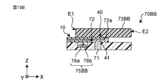
- FIGS. 19A and 19B are schematic views showing the operation of the detection unit 75BB of the modified example 7.
- the detection unit 75BB may be composed of a photo sensor as in the modified example 6.
- the detection unit 75BB has a light emitting unit 76a that emits light and a light receiving unit 76b that receives light.
- the light emitting unit 76a and the light receiving unit 76b are arranged on the arrangement surface 72. Specifically, the light emitting unit 76a and the light receiving unit 76b are arranged side by side in the holes provided in the arrangement surface 72. The light emitting unit 76a irradiates light toward the pressing member 73BB. The light receiving unit 76b receives the light emitted from the light emitting unit 76a and reflected by the oral cavity device 10.
- the detection unit 75BB detects that the oral cavity device 10 is removed from the attachment / detachment operation unit 70BA when the light receiving unit 76b does not receive the light from the light emitting unit 76a.
- the detection unit 75BB detects that the oral appliance 10 is attached to the attachment / detachment operation unit 70BA when the light receiving unit 76b receives the reflected light from the oral appliance 10.
- the oral appliance 10 may be formed of a reflective material that reflects light. With such a configuration, the light emitted from the light emitting portion 76a by the oral appliance 10 is easily reflected. Therefore, the detection accuracy can be improved.
- FIGS. 20A and 20B are schematic perspective views of an example of the oral apparatus 1C according to the third embodiment of the present invention.
- the display of the display unit 90 is omitted.
- the extension direction of the main body 60C of the oral main body device 50C is the same as the attachment / detachment direction of the oral device 10C, and the attachment / detachment operation unit 70C is configured to deform and fix the oral device 10C. This is different from the first embodiment.
- the main body 60C of the oral main body device 50C is formed of a rod-shaped member extending in the same direction as the attachment / detachment direction of the oral device 10C.
- the attachment / detachment direction of the oral device 10C is the X direction in FIGS. 20A and 20B.
- the guard 80C is formed by a convex portion protruding in a direction intersecting the attachment / detachment direction of the oral device 10C.
- the guard 80C is provided on the side of the main body 60C opposite to the side where the attachment / detachment operation portion 70C is provided.
- the guard 80C projects outward from the grip portion 61C.
- the guard 80C is formed with an inclined surface that prevents liquid such as saliva from flowing toward the grip portion 61C. This makes it possible to prevent saliva from flowing to the grip portion 61C.
- the oral appliance 10C is formed in a sheet shape having a deformable longitudinal direction. In the third embodiment, the entire oral device 10C has flexibility.
- the attachment / detachment operation unit 70C is configured to deform and fix the oral appliance 10C.
- the attachment / detachment operation unit 70C has an arrangement surface 72C that is curved in a concave or convex shape, and a pressing member 73C that is curved in a concave or convex shape along the shape of the arrangement surface 72C.
- FIG. 21A is a schematic partially enlarged cross-sectional view showing an enlarged example of the attachment / detachment operation unit 70C.
- 21B is a schematic exploded cross-sectional view of the attachment / detachment operation portion of FIG. 21A.
- 21A and 21B show cross-sectional views when the attachment / detachment operation unit 70C is cut in the YZ plane.
- the arrangement surface 72C is formed by being curved in a concave shape. Specifically, the arrangement surface 72C is formed by being recessed in a trapezoidal shape.
- the arrangement surface 72C includes a flat bottom surface 72aa and a plurality of inclined surfaces 72ab, 72ac extending inclined toward the bottom surface 72aa.
- a plurality of connection terminals 71 are arranged on the bottom surface 72aa of the arrangement surface 72C.
- the pressing member 73C is formed by being curved in a convex shape along the shape of the arrangement surface 72C. Specifically, the pressing member 73C is formed in a trapezoidal shape.
- the pressing member 73C includes a flat bottom surface 73ca and a plurality of inclined surfaces 72ab, 72ac extending inclined toward the bottom surface 73ca.
- the oral device 10C is attached to the attachment / detachment operation unit 70C by pressing the oral device 10C arranged on the arrangement surface 72C by the pressing member 73C.
- the oral appliance 10C is sandwiched between the pressing member 73C and the arranging surface 72C, so that the oral appliance 10C is fixed in a deformed state along the shape of the pressing member 73C and the arranging surface 72C.
- the oral appliance 10C is deformed into a trapezoidal shape protruding downward in the Z direction.
- the oral appliance 10C is provided between the bottom surface 72aa of the arrangement surface 72C and the bottom surface 73ca of the pressing member 73C, between the inclined surface 72ab of the arrangement surface 72C and the inclined surface 73cc of the pressing member 73C, and the arrangement surface 72C. It is sandwiched between the inclined surface 72ac and the inclined surface 73cc of the holding member 73C.
- the plurality of electrodes 41 of the oral appliance 10C are electrically connected to the plurality of connection terminals 71 by physically contacting the plurality of connection terminals 71 arranged on the bottom surface 72aa of the arrangement surface 72C.
- the oral appliance 10C is deformed into a trapezoidal shape and fixed to the attachment / detachment operation unit 70C.
- the attachment / detachment operation unit 70C can be attached by deforming the flexible oral device 10C into a trapezoidal shape or the like.
- the arrangement surface 72C is curved in a concave or convex shape.
- the pressing member 73C is curved in a concave or convex shape along the shape of the arrangement surface 72.
- the attachment / detachment operation unit 70C deforms and fixes the flexible oral device C. Therefore, when the force applied to the oral device 10C is released and the fixation is released, the force applied to the oral device 10C can be easily removed from the attachment / detachment operation unit 70C by the restoring force of the oral device 10C.
- the arrangement surface 72C and the pressing member 73C are formed in a trapezoidal shape.
- a plurality of connection terminals 71 are arranged on the flat bottom surface 72aa of the arrangement surface 72C. At the bottom surface 72aa, the plurality of electrodes 41 of the oral appliance 10C and the plurality of connection terminals 71 are in physical contact with each other. This facilitates electrical connection between the plurality of electrodes 41 and the plurality of connection terminals 71.
- the arrangement surface 72C may be curved in a concave or convex shape.
- the pressing member 73C may be curved in a concave or convex shape along the shape of the arrangement surface 72.
- the arrangement surface 72C may be formed so as to project in a trapezoidal shape, and the pressing member 73C may be formed in a trapezoidal shape.
- connection terminals 71 are arranged on the bottom surface 72aa of the arrangement surface 72C
- the present invention is not limited to this.
- the plurality of connection terminals 71 may be arranged on the inclined surfaces 72ab and 72ac.
- the plurality of connection terminals 71 may be arranged on the bottom surface 73ca, the inclined surfaces 73cc, and 73cc of the pressing member 73C.
- FIG. 22 is a schematic partially enlarged cross-sectional view showing the attachment / detachment operation unit 70CA of the modified example 8 in an enlarged manner.
- the attachment / detachment operation unit 70CA has a semicircularly recessed arrangement surface 72CA and a semicircular pressing member 73CA that follows the shape of the arrangement surface 72CA.
- the pressing member 73CA has a semicircular surface 73cd formed in a semicircular shape.
- the oral appliance 10C is fixed in a semicircularly deformed state by being sandwiched between the arrangement surface 72CA and the semicircular surface 73cd of the pressing member 73CA. In other words, the oral appliance 10C is fixed in a V-shaped shape protruding downward when viewed from the X direction by being sandwiched between the arrangement surface 72CB and 73cd of the pressing member 73CB.
- FIG. 23 is a schematic partially enlarged cross-sectional view showing the attachment / detachment operation unit 70CB of the modified example 9 in an enlarged manner.
- the attachment / detachment operation unit 70CB has an arrangement surface 72CB recessed in a triangular shape and a triangular pressing member 73CB that follows the shape of the arrangement surface 72CB.
- the arrangement surface 72CB has two inclined surfaces 72ad and 72ae.
- the pressing member 73CB has two inclined surfaces 72ce and 72cf.
- the oral appliance 10C is fixed in a triangular deformed state by being sandwiched between the arrangement surface 72CB and the pressing member 73CB.
- the oral appliance 10C is sandwiched between the inclined surface 72ad of the arrangement surface 72CB and the inclined surface 73ce of the pressing member 73CB, and between the inclined surface 72ae of the arrangement surface 72CB and the inclined surface 73cf of the pressing member 73CB. Is done. As a result, the oral appliance 10C is fixed in a V-shaped deformed state protruding downward when viewed from the X direction.
- FIGS. 24A and 24B are schematic perspective views of an example of the oral apparatus 1D according to the fourth embodiment of the present invention.
- the display of the display unit 90 is omitted.
- the fourth embodiment is different from the first embodiment in that the positions of the arrangement surface 72D and the pressing member 73D are reversed in the attachment / detachment operation unit 70D. Further, in the fourth embodiment, as in the third embodiment, the attachment / detachment operation unit 70D is configured to deform and fix the oral appliance 10D.
- the holding member 73D is arranged below the arrangement surface 72D.
- the oral device 10D arranged on the arrangement surface 72D is pressed and fixed by pushing up the pressing member 73D.
- the pressing member 73D is pushed down to release the pressure on the oral device 10D, and the fixation is released.
- the oral main body device 50D has a so-called gun type configuration.
- the pressing member 73D has a ring-shaped member 77.
- the ring-shaped member 77 is integrally formed with the pressing member 73D.
- the movement of the pressing member 73D can be controlled.
- the user inserts the index finger into the ring-shaped member 77 while gripping the grip portion 61D of the main body portion 60D.
- the user can attach / detach the oral device 10D by operating the ring-shaped member 77 with the index finger.
- the ring-shaped member 77 can realize the function of the guard 80 of the first embodiment. For example, when the oral device 10D hangs down, the ring-shaped member 77 can protect the user's finger.
- FIG. 25 is a schematic partially enlarged cross-sectional view showing an enlarged example of the attachment / detachment operation unit 70D.
- FIG. 25 shows a state in which the oral appliance 10D is attached to the attachment / detachment operation unit 70D. Note that FIG. 25 shows a cross-sectional view when the attachment / detachment operation unit 70D is cut on the YZ plane.
- the attachment / detachment operation unit 70D has a semicircularly recessed arrangement surface 72D and a semicircular pressing member 73D that follows the shape of the arrangement surface 72D.
- a plurality of connection terminals 71 are arranged on the arrangement surface 72D.
- the pressing member 73D has a semicircular surface 73cg formed in a semicircular shape.
- the oral appliance 10D is fixed in a semicircularly deformed state by being sandwiched between the arrangement surface 72D and the semicircular surface 73cg of the pressing member 73D.
- the oral appliance 10D is deformed into a semicircular shape protruding upward in the Z direction.
- the plurality of electrodes 41 of the oral appliance 10D physically come into contact with the plurality of connection terminals 71 arranged on the arrangement surface 72D. As a result, the plurality of electrodes 41 and the plurality of connection terminals 71 are electrically connected.
- the pressing member 73D is arranged below the arrangement surface 72D.
- the pressing member 73D has a ring-shaped member 77. With such a configuration, the user can easily attach / detach the oral device 10D by operating the ring-shaped member 77 of the pressing member 73D.
- the attachment / detachment operation unit 70D has a semicircularly recessed arrangement surface 72D and a semicircular pressing member 73D that follows the shape of the arrangement surface 72D. With such a configuration, the oral appliance 10D is fixed in a state of being deformed into a semicircle protruding upward in the Z direction. This suppresses the sagging of the oral appliance 10D and facilitates fitting to the tongue portion in the oral cavity.
- the arrangement surface 72D and the pressing member 73D are formed in a semicircular shape, but the present invention is not limited to this.
- the arrangement surface 72D and the pressing member 73D may be formed by being curved in a concave or convex shape.
- connection terminals 71 are arranged on the arrangement surface 72
- the present invention is not limited to this.
- the plurality of connection terminals 71 may be arranged on the holding member 73D.
- FIG. 26 is a schematic partially enlarged cross-sectional view showing the attachment / detachment operation unit 70DA of the modified example 10 in an enlarged manner.
- FIG. 26 shows a state in which the oral appliance 10D is attached to the attachment / detachment operation unit 70DA. Note that FIG. 26 shows a cross-sectional view when the attachment / detachment operation unit 70DA is cut on the YZ plane.
- the attachment / detachment operation unit 70DA has a semicircularly recessed arrangement surface 72DA and a semicircular pressing member 73DA that follows the shape of the arrangement surface 72DA.
- the pressing member 73DA has a semicircular surface 73ch formed in a semicircular shape.
- the plurality of connection terminals 71 are arranged on the semicircular surface 73ch. Even in such a configuration, the plurality of electrodes 41 of the oral appliance 10D and the plurality of connection terminals 71 can be electrically connected.
- FIG. 27 is a schematic partially enlarged cross-sectional view showing the attachment / detachment operation unit 70DB of the modified example 11 in an enlarged manner.
- FIG. 27 shows a state in which the oral appliance 10D is removed from the attachment / detachment operation unit 70DB. Note that FIG. 27 shows a cross-sectional view when the attachment / detachment operation unit 70DB is cut on the YZ plane.
- the attachment / detachment operation unit 70DB has a semicircularly recessed arrangement surface 72DB and a semicircular pressing member 73DB that follows the shape of the arrangement surface 72DB.
- the pressing member 73DB has a semicircular surface 73ci formed in a semicircular shape.
- the plurality of connection terminals 71 are arranged on both the arrangement surface 72DB and the semicircular surface 73ci. Even in such a configuration, the plurality of electrodes 41 of the oral appliance 10D and the plurality of connection terminals 71 can be electrically connected.
- the plurality of electrodes 41 are arranged on the upper surface of the oral appliance 10D or the plurality of electrodes 41 are arranged on the lower surface of the oral appliance 10D, the plurality of electrodes 41 and the plurality of connections are made.
- the oral appliance 10D can be attached to the attachment / detachment operation unit 70DB while being electrically connected to the terminal 71.
- FIG. 28 is a block diagram showing a main configuration of an example of the oral apparatus 1E according to the fifth embodiment of the present invention.
- the fifth embodiment is different from the first embodiment in that the functional unit 20E of the oral appliance 10E has the energy irradiation unit 22 and the oral main body device 50E controls the energy irradiation unit 22.
- the functional unit 20E has an energy irradiation unit 22 that irradiates the oral cavity with energy.
- the oral device 10E is a laser treatment device.
- the oral appliance 10E is detachably attached to and used as the oral main body device 50E.
- FIG. 29A is a schematic view showing an example of the oral appliance 10E.
- 29B is a schematic cross-sectional view of an example of the oral appliance of FIG. 29A.
- the functional unit 20E has a plurality of energy irradiation units 22.
- the functional unit 20E has four energy irradiation units 22.
- the plurality of energy irradiation units 22 are, for example, vertical cavity surface emitting lasers (VCSEL: Vertical Cavity Surface Emitting LASER).
- VCSEL Vertical Cavity Surface Emitting LASER
- the plurality of energy irradiation units 22 are mounted on the first main surface PS1 of the wiring layer 11 and are covered with a transparent resin film 14 from above.
- the lasers from the plurality of energy irradiation units 22 pass through the resin film 14 and irradiate the irradiation site in the oral cavity.
- the oral main body device 50E includes an input unit 91.
- the input unit 91 acquires input information for operating the energy irradiation unit 22.
- the user inputs input information to the input unit 91.
- the input unit 91 may be one or more operation buttons, a touch panel, a microphone, or the like.
- the input information input to the input unit 91 is transmitted to the control unit 62.
- the input information includes, for example, laser irradiation, laser stop, timer, output value, and the like.
- the control unit 62 receives the input information from the input unit 91 and controls the operation of the oral appliance 10E based on the input information.
- the control unit 62 controls a plurality of energy irradiation units 22 based on the input information. For example, when input information for laser irradiation is input to the input unit 91, the control unit 62 controls a plurality of energy irradiation units 22 of the oral instrument 10E and causes the plurality of energy irradiation units 22 to irradiate the laser.
- the oral main body device 50E can be detachably attached to the oral device 10E having the energy irradiation unit 22 to control the operation of the oral device 10E. Further, after using the oral device 10E, the oral device 10E can be easily removed from the main body device 50E.
- the energy irradiation unit 22 is a vertical resonator surface emitting laser
- the present invention is not limited to this.
- the energy irradiation unit 22 only needs to be able to irradiate energy.
- the functional unit 20E may have one or a plurality of energy irradiation units 22.
- FIG. 30 is a schematic view showing the oral appliance 10EA of the modified example 12.
- the oral device 10EA is used as a high frequency treatment device.
- the plurality of energy irradiation units 22a of the functional unit 20EA are a plurality of electrodes capable of passing a high frequency current.
- a high-frequency current is supplied between the plurality of electrodes while the plurality of electrodes are in contact with the oral cavity.
- the supply of high frequency current is controlled by the main body device 50E.
- the oral device 10EA may be a low frequency treatment device. In this case, a low frequency current is supplied between the plurality of electrodes.
- FIG. 31A is a schematic view showing the oral appliance 10EB of the modified example 13.
- FIG. 31B is a schematic cross-sectional view of the oral appliance 10EB of the modification 13 of FIG. 31A.
- the oral appliance 10EB is used as a hyperthermia treatment device.
- the energy irradiation unit 22b of the functional unit 20EB is a seat heater.
- the seat heater heats by utilizing the heat generated by the resistor.
- the oral appliance 10EB may be covered with the heat insulating material 15 except for the portion heated by the energy irradiation unit 22b.
- FIG. 32 is a block diagram showing a main configuration of an example of the oral apparatus 1F according to the sixth embodiment of the present invention.
- the sixth embodiment is different from the first embodiment in that the electrical connection portion of the oral appliance 10F is an RFID (Radio Frequency Identification) tag 43, and the electrical connection conductor of the oral main body device 50F is an antenna 78.
- RFID Radio Frequency Identification
- the connection portion 40E has an RFID tag 43 as an electrical connection portion.
- the RFID tag 43 is electrically connected by wirelessly connecting to the electrical connection conductor of the oral main body device 50F. That is, the RFID tag 43 is electrically connected to the antenna 78 of the oral main body device 50F in a non-contact manner.
- FIG. 33 is a schematic view showing an example of the oral appliance 10F.
- FIG. 34 is a schematic cross-sectional view of an example of the oral appliance 10F of FIG. 33.
- the RFID tag 43 is arranged at the connection portion 40F in the wiring layer 11.
- the RFID tag 43 is covered with a plurality of insulating layers 12, 13. That is, the RFID tag 43 is not exposed from the plurality of insulating layers 12 and 13.
- FIG. 35 is a schematic diagram of an example of the RFID tag 43. As shown in FIG. 35, the RFID tag 43 has an antenna 44 and an IC chip 45 connected to the antenna 44.
- the antenna 44 is formed by winding a conductive linear member in a coil shape.
- the antenna 44 is formed, for example, by a wiring conductor pattern.
- the IC chip 45 is, for example, a package of an RFIC chip (bare chip) having an input / output terminal.
- the IC chip 45 is an IC chip on which an RF circuit for an RFID tag, a memory circuit, a control circuit, and the like are mounted.
- the IC chip 45 is connected to the sensor unit 21 of the functional unit 20 via the wiring 31.
- FIG. 36 is a schematic circuit diagram of an example of the RFID tag 43.
- the antenna 44 is connected to the IC chip 45.
- a chip capacitor C1 is connected in parallel to the antenna 44.
- the chip capacitor C1 is, for example, a laminated ceramic chip component.
- the antenna 44, the chip capacitor C1, and the capacitive component of the IC chip 45 itself constitute an antenna resonance circuit having a resonance frequency.
- the circuit is an example, and the resonance circuit of the RFID tag 43 is not limited to this.
- FIG. 37 is a schematic partially enlarged cross-sectional view showing an enlarged example of the attachment / detachment operation unit 70F.
- FIG. 37 shows a state in which the oral device 10F is attached to the attachment / detachment operation unit 70F, and the oral device 10F and the main body device 50 are electrically connected in a non-contact manner.
- the attachment / detachment operation unit 70F has an antenna 78.
- the antenna 78 may be referred to as a main body side antenna 78.
- the attachment / detachment operation unit 70F has the same configuration as the attachment / detachment operation unit 70 of the first embodiment, except that the antenna 78 is provided instead of the connection terminal 71.
- the main body side antenna 78 is formed by winding a conductive linear member in a coil shape.
- the main body side antenna 78 is formed, for example, by a wiring conductor pattern.
- the main body side antenna 78 is housed inside the main body device 50F.
- the main body side antenna 78 is arranged below the arrangement surface 72.
- the main body side antenna 78 is located below the antenna 44 of the RFID tag 43 in a state where the oral appliance 10F is arranged on the arrangement surface 72 and attached to the attachment / detachment operation unit 70F. That is, in a state where the oral appliance 10F is arranged on the arrangement surface 72 and attached to the attachment / detachment operation unit 70F, the main body side antenna 78 faces the antenna 44 of the RFID tag 43.
- the RFID tag 43 and the main body side antenna 78 of the main body device 50 face each other, the RFID tag 43 and the main body side antenna 78 are magnetically coupled. As a result, an induced current flows through the antenna 44, and the IC chip 45 operates. This makes it possible to use the oral appliance 10F.
- the electrical connection part of the oral appliance 10F is an RFID tag 43.
- the electrical connection conductor of the oral main body device 50F is the antenna 78.
- the attachment / detachment operation unit 70F is electrically connected by wirelessly connecting the RFID tag 43 and the antenna 78. With such a configuration, the oral device 10F can be easily attached and detached, and the oral device 10F and the oral main body device 50F can be easily electrically connected.
- FIGS. 38A and 38B are schematic perspective views of an example of the oral apparatus 1G according to the seventh embodiment of the present invention.
- FIG. 38A shows a state in which the oral appliance 10G is removed from the oral main body device 50G.
- FIG. 38B shows a state in which the oral appliance 10G is attached to the oral main body device 50G.
- the occlusal force meter is a device that measures the force at the time of occlusal, that is, the occlusal force.
- the oral device 10G acquires information related to the quotient force and transmits the information related to the quotient force to the oral main body device 50G.
- the oral main body device 50G calculates the quotient force based on the information related to the occlusal force acquired by the oral appliance 10G.
- the oral appliance 10G is detachably attached to the attachment / detachment operation unit 70G of the oral main body device 50G.
- FIG. 39A is a schematic plan view of an example of the oral appliance 10G according to the seventh embodiment of the present invention.
- FIG. 39B is a schematic cross-sectional view taken along the line AA of the oral appliance 10G of FIG. 39A.
- the oral appliance 10G includes a functional portion 20G and a connecting portion 40G.
- the functional unit 20G has a sensor unit 21G that detects information related to the user's occlusal force.
- the sensor unit 21G is a portion that is bitten by the user's teeth when measuring the occlusal force.
- the sensor unit 21G includes an insulating layer 23, an electrode 24, a weighted dispersion plate 25, and a pressure receiving unit 26.
- two electrodes 24 are arranged on both sides of the insulating layer 23, and two weighted dispersion plates 25 and two pressure receiving portions 26 are arranged outside the electrodes 24. ..
- the insulating layer 23 is formed of a plate-shaped resin member.
- the resin member for example, a thermoplastic elastomer is used.
- the insulating layer 23 has a length of 15 mm, a width of 30 mm, and a thickness of 0.8 mm.
- the length means the dimension in the X direction
- the width means the dimension in the Y direction
- the thickness means the dimension in the Z direction.
- the electrode 24 is made of a plate-shaped conductive member.
- the conductive member for example, a flexible printed circuit board is used.
- the electrode 24 has a length of 15 mm, a width of 30 mm, and a thickness of 0.1 mm.
- the electrodes 24 are arranged so as to sandwich the insulating layer 23. Further, the electrode 24 is integrally formed with the electrical connection portion 41G of the connection portion 40G described later.
- the weight distribution plate 25 is a plate-shaped member that disperses the weight applied to the sensor unit 21G. Specifically, the weight distribution plate 25 disperses the weight received by the pressure receiving unit 26.
- the weighted dispersion plate 25 is made of a material harder than the insulating layer 23.
- the weighted dispersion plate 25 is made of a material such as SUS.
- the weighted dispersion plate 25 has a length of 30 mm, a width of 15 mm, and a thickness of 1 mm.
- the weighted dispersion plate 25 is arranged outside the electrode 24 and sandwiches the insulating layer 23 and the electrode 24. Further, a part of the weighted dispersion plate 25 constitutes a connecting portion 40G.
- the pressure receiving portion 26 is a portion that comes into contact with the user's teeth and receives pressure due to the occlusal force.
- the pressure receiving portion 26 is formed of a plate-shaped resin member.
- the resin member for example, rubber is used.
- the pressure receiving portion 26 has a length of 30 mm, a width of 15 mm, and a thickness of 2 mm.
- the pressure receiving portion 26 is arranged outside the weighted dispersion plate 25, and sandwiches the insulating layer 23, the electrode 24, and the weighted dispersion plate 25.
- the connection portion 40G is a portion that is detachably attached to the attachment / detachment operation portion 70G of the oral main body device 50G, and is provided at the rear end on the opposite side to the tip of the oral appliance 10G.
- the connecting portion 40G has a plurality of engaging portions 46 and a plurality of electrical connecting portions 41G.
- the plurality of engaging portions 46 are composed of a pair of plate-shaped members arranged so as to face each other at intervals.
- the plurality of electrical connection portions 41G are composed of a pair of electrodes arranged between the plurality of engagement portions 46. Further, each of the plurality of electrical connection portions 41G is arranged inside the plurality of engagement portions 46.
- the engaging portion 46 is composed of a part of the weighted dispersion plate 25, and the electrical connection portion 41G is composed of a part of the electrode 24.
- the engaging portion 46 is formed by projecting one end of the weighted dispersion plate 25 from the insulating layer 23 and the pressure receiving portion 26.
- the electrical connection portion 41G is formed by projecting one end of the electrode 24 from the insulating layer 23 and the pressure receiving portion 26.
- the engaging portion 46 is provided with a lock hole 46a penetrating in the thickness direction.
- the lock hole 46a is formed in a rectangular shape when viewed in the thickness direction of the oral appliance 10G. Further, the electrical connection portion 41G is arranged at a position overlapping the lock hole 46a when viewed in the thickness direction of the oral appliance 10G.
- the lock hole 46a is a hole into which the protrusion 73e of the holding member 73G of the attachment / detachment operation unit 70G, which will be described later, is inserted.
- the functional unit 20G is arranged in the oral cavity of the user, and the sensor unit 21G of the functional unit 20G is bitten from the vertical direction to acquire information related to the quotient force. Further, the information related to the quotient force acquired by the sensor unit 21G is transmitted to the oral main body device 50G via the connection unit 40G. In the oral main body device 50G, the calculation unit 63 calculates the quotient force based on the information related to the quotient force acquired by the oral appliance 10G.
- the oral appliance 10G pressure is applied to the pressure receiving portion 26 by the user biting the sensor portion 21G from above and below.
- the weighted dispersion plate 25 evenly distributes the pressure.
- the insulating layer 23 is deformed in a state where the pressure is evenly applied to the insulating layer 23.
- the oral appliance 10G acquires capacitance information as information related to the user's occlusal force.
- connection portion 40G of the oral appliance 10G the electrical connection portion 41G and the electrical connection conductor 71G of the oral main body device 50G are electrically connected by physical contact. Therefore, the information on the capacitance acquired by the oral appliance 10G is transmitted to the oral main body device 50G via the electrical connection portion 41G and the electrical connection conductor 71G.
- the calculation unit 63 calculates the quotient force based on the information of the capacitance acquired by the oral appliance 10G.
- FIGS. 40A-40C is a schematic diagram showing an example of the operation of the attachment / detachment operation unit 70G.
- the oral main body device 50G includes a substrate 72G provided with an electrical connection conductor 71G and a detachable operation unit 70G.
- the substrate 72G is formed in a plate shape and is arranged inside the main body 60G. One end of the substrate 72G is arranged on the opening 64 side provided at the tip of the main body 60G.
- the opening 64 is a portion into which the connection portion 40G of the oral appliance 10G is inserted. Further, the opening 64 is provided with a guide 64a when the oral device 10G is inserted.
- a plurality of electrical connection conductors 71G are provided on both main surfaces of the substrate 72G.
- the substrate 72G has a first arrangement surface 72GA and a second arrangement surface 72GB opposite to the first arrangement surface 72GA.
- One electric connection conductor 71G is provided on the first arrangement surface 72GA of the substrate 72G, and one electric connection conductor 71G is provided on the second arrangement surface 72GB of the substrate 62G.
- the plurality of electrical connection conductors 71G are provided on one end side of the substrate 72G.
- the plurality of electrical connection conductors 71G are formed of a plurality of connection terminals.
- a pad electrode may be used as the connection terminal.
- the pad electrode is made of, for example, a conductive material.
- the pad electrode is formed in a rectangular shape, for example, when viewed from the main surface side of the substrate 72G.
- the pad electrode may be made of, for example, the same material as the electrode 24.
- the attachment / detachment operation unit 70G has a plurality of pressing members 73G.
- the plurality of pressing members 73G are members that can operate the application and release of the force to the oral appliance 10G.
- the plurality of pressing members 73G are arranged on both main surfaces of the substrate 72G, respectively, and are configured to apply a force in a direction intersecting both main surfaces of the substrate 72G. "Applying a force in a direction intersecting both main surfaces of the substrate 72G" means applying a force in a direction approaching the substrate 72G.
- the plurality of pressing members 73G have at least two pressing members 73G.
- the plurality of pressing members 73G are arranged on both main surface sides of the substrate 72G, that is, on the first arrangement surface 72GA side and the second arrangement surface 72GB side inside the main body portion 60G.
- the plurality of pressing members 73G are configured to apply a force in a direction intersecting both main surfaces of the substrate 72G at a portion provided with a plurality of electrical connection conductors 71G, that is, a plurality of connection terminals.
- the pressing member 73G applies a force to the connection portion 40G of the oral appliance 10G in a state where the electrical connection portion 41G (plurality of electrodes) and the plurality of electrical connection conductors 71G (plurality of connection terminals) are in contact with each other.
- the holding member 73G can fix the oral appliance 10G to the oral main body device 50G in a state where the electrical connection portion 41G of the oral appliance 10G and the electrical connection conductor 71G are electrically connected.
- the pressing member 73G is formed of a rod-shaped member having one end and the other end. One end of the pressing member 73G is arranged on the opening 64 side, and the other end of the pressing member 73G is arranged inside the main body portion 60G on the opposite side of the opening 64.
- Each of the plurality of pressing members 73G has protrusions 73e protruding toward both main surfaces of the substrate 72G.
- the protrusion 73e is provided at one end of the pressing member 73G.
- the protrusion 73e has, for example, a round and curved shape.
- the protrusion 73e is inserted into the lock hole 46a provided in the engaging portion 46 of the connecting portion 40G in a state where the connecting portion 40G of the oral appliance 10G is attached to the oral main body device 50G. As a result, the protrusion 73e engages with the engaging portion 46, and the oral appliance 10G is fixed to the oral main body device 50G.
- each of the plurality of pressing members 73G has an operation unit 79 located in the operation hole 65 of the main body unit 60G.
- the operation unit 79 is provided on the other end side of the pressing member 73G and protrudes from the operation hole 65.
- the operation unit 79 is formed by bending the pressing member 73G into a U shape. The shape of the operation unit 79 is not limited to this.
- a plurality of elastic members 79a are arranged on the other end side of the plurality of pressing members 73G.
- the plurality of elastic members 79a are arranged on both main surfaces of the substrate 72G, and urge the other ends of the plurality of pressing members 73G in a direction away from both main surfaces of the substrate 72G.
- one elastic member 79a is arranged on the first arrangement surface 72GA
- one elastic member 79a is arranged on the second arrangement surface 72GB.
- the elastic member 79a is, for example, a spring.
- Each of the plurality of pressing members 73G has a rotating shaft 74G, and rotates about the rotating shaft 74G.
- the rotating shaft 74G is provided between one end and the other end of the pressing member 73G.
- the pressing member 73G rotates about the rotation shaft 74G.
- one end side of the pressing member 73G approaches the substrate 72G, while the other end side of the pressing member 73G separates from the substrate 72G.
- the pressing member 73G rotates about the rotation shaft 74G, and one end side of the pressing member 73G is separated from the substrate 72G, while the other end side of the pressing member 73G is. Approaches the substrate 72G.
- connection portion 40G of the oral appliance 10G is inserted toward the opening 64 of the main body portion 60G.
- the connection portion 40 of the oral appliance 10G is inserted into the opening 64 along the guide 64a.
- the oral appliance 10G is inserted into the opening 64 so that the guide 64a is located between the pair of engaging portions 46.
- the protrusion 73e and the engaging portion 46 are engaged with each other by inserting the protrusion 73e of the holding member 64G into the lock hole 46a of the engaging portion 46 of the connecting portion 40G.
- the other end side of the pressing member 73G is urged in a direction away from the substrate 72G by the elastic member 79a. Therefore, a force is applied to one end side of the pressing member 73G in a direction approaching the substrate 72G.
- the state in which the protrusion 73e of the pressing member 73G is inserted into the lock hole 46a that is, the state in which the protrusion 73e is engaged with the engaging portion 46 can be maintained.
- the oral appliance 10G is fixed to the oral main body device 50G in a state where the electrical connection portion 41G and the electrical connection conductor 71G are electrically connected.
- the operation portion 79 of the pressing member 73G is pushed in a direction approaching the substrate 72G to move the protrusion 73e of the pressing member 73G in a direction away from the substrate 72G.
- the protrusion 73e of the holding member 73G moves to the outside of the lock hole 46a, the engagement between the protrusion 73e and the engaging portion 46 is released, and the oral appliance 10G can be removed from the oral main body device 50G.
- the electrical connection portion 41G of the oral appliance 10G has a plurality of electrodes.
- the electrical connection conductor 71G of the oral main body device 50G has a plurality of connection terminals provided on both main surfaces of the substrate 72G.
- the attachment / detachment operation unit 70G has a plurality of pressing members 73G arranged on both main surfaces of the substrate 72G and applying a force in a direction intersecting both main surfaces of the substrate 72G.
- the plurality of pressing members 73G fix the oral cavity device 10 by applying a force in a direction intersecting both main surfaces of the substrate 72G in a state where the plurality of electrodes and the plurality of connection terminals are in contact with each other. With such a configuration, the oral device 10G can be easily attached and detached, and the oral device 10G and the oral main body device 50G can be easily electrically connected.
- Each of the plurality of pressing members 73G has protrusions 73e protruding toward both main surfaces of the substrate 72G. With such a configuration, the plurality of pressing members 73G can easily come into contact with the oral device 10G, and the oral device 10G can be easily and firmly fixed to the oral main body device 50G.
- the lock hole 46a is not an essential configuration and may not be provided in the engaging portion 46.
- the engaging portion 46 is composed of a part of the weighted dispersion plate 25
- the present invention is not limited to this.
- the engaging portion 46 may be formed of a member different from the weighted dispersion plate 25.
- the electrical connection portion 41G is an electrode integrally formed with the electrode 24
- the present invention is not limited to this.
- the electrical connection portion 41G may be formed of a member different from the electrode 24.
- a wiring portion may be provided between the electrode 24 and the electrical connection portion 41G.
- the oral appliance 10G includes the weighted dispersion plate 25
- the present invention is not limited to this.
- the weighted dispersion plate 25 is not an essential configuration.
- the pressing member 73G may be the pressing members 73, 73AA of the modified examples 1 to 5 of the first embodiment.
- the oral appliance 10G acquires the information of the capacitance as the information related to the occlusal force of the user has been described, but the present invention is not limited to this.
- the oral appliance 10G may acquire information for calculating the occlusal force as information related to the occlusal force of the user.
- FIGS. 41A and 41B are schematic cross-sectional views of an example of the oral apparatus 1H according to the eighth embodiment of the present invention.
- FIG. 41A shows a state in which the oral appliance 10H is removed from the oral main body device 50H.
- FIG. 41B shows a state in which the oral appliance 10H is attached to the oral main body device 50H.
- the oral device 1H is an occlusal force meter.
- the description of the occlusal force meter will be omitted because it is the same as that of the seventh embodiment.
- the eighth embodiment is different from the seventh embodiment in that the pressing member 73H is arranged only on one main surface of the substrate 72H.
- the oral appliance 10H is detachably attached to the attachment / detachment operation unit 70H of the oral main body device 50H.
- FIG. 42A is a schematic bottom view of an example of the oral appliance 10H according to the eighth embodiment of the present invention.
- 42B is a schematic cross-sectional view of the oral cavity device 10H of FIG. 42A cut along the line BB.
- the oral appliance 10H includes a functional portion 20H and a connecting portion 40H.
- the functional unit 20H has a sensor unit 21H that detects information related to the user's occlusal force.
- the sensor unit 21H is a portion that is bitten by the user's teeth when measuring the occlusal force.
- the sensor unit 21H includes an insulating layer 23, an electrode 24, a weighted dispersion plate 25, and a pressure receiving unit 26. Since the insulating layer 23, the electrode 24, the weighted dispersion plate 25, and the pressure receiving portion 26 are the same as those in the seventh embodiment, the description thereof will be omitted.
- connection portion 40H is a portion that is detachably attached to the attachment / detachment operation portion 70H of the oral main body device 50H, and is provided on the rear end side opposite to the tip of the oral appliance 10H.
- the connection portion 40H includes an engagement portion 46H and a plurality of electrical connection portions 41H.
- the engaging portion 46H is composed of a plate-shaped member.
- the plurality of electrical connection portions 41H are composed of, for example, electrodes.
- each of the plurality of electrical connection portions 41H is arranged on the inner surface side of the engagement portion 46H.
- the inner surface side of the engaging portion 46H is the surface on the side where the insulating layer 23 is arranged in the thickness direction (Z direction) of the oral cavity device 10H.
- three plurality of electrical connection portions 41H are arranged in the engagement portion 46H.
- the number of electrical connection portions 41H is not limited to three, and may be one or a plurality.
- the engaging portion 46H is composed of a part of the weighted dispersion plate 25, and the electrical connecting portion 41H is composed of a part of the electrode 24.
- the engaging portion 46H is formed by projecting one end of the weighted dispersion plate 25 from the insulating layer 23 and the pressure receiving portion 26.
- the electrical connection portion 41H is formed by projecting one end of the electrode 24 from the insulating layer 23 and the pressure receiving portion 26.
- the engaging portion 46H is provided with a lock hole 46b penetrating in the thickness direction.
- the lock hole 46b is formed in a rectangular shape when viewed in the thickness direction of the oral appliance 10H.
- the lock hole 46a is a hole into which the protrusion 73f of the holding member 73H of the attachment / detachment operation unit 70H, which will be described later, is inserted.
- the engaging portion 46H is provided with two lock holes 46b at intervals. Further, when viewed in the thickness direction of the oral appliance 10H, the plurality of electrical connection portions 41H are arranged between the two lock holes 46b.
- connection portion 40H the electrical connection portion 41H and the electrical connection conductor 71H of the oral main body device 50H are electrically connected by physical contact.
- FIGS. 41A and 41B an example of the configuration of the oral main body device 50H and the operation of the attachment / detachment operation unit 70H will be described.
- the oral main body device 50H includes a substrate 72H provided with a plurality of electrical connection conductors 71H, and a detachable operation unit 70H.
- the substrate 72H is formed in a plate shape and is arranged inside the main body portion 60H. One end of the substrate 72H is arranged on the opening 64H side provided at the tip of the main body 60H.
- the opening 64H is a portion into which the connection portion 40H of the oral appliance 10H is inserted.
- FIG. 43 is a schematic partial perspective view of an example of the oral main body device 50H according to the eighth embodiment of the present invention. As shown in FIG. 43, the connection portion 40H of the oral appliance 10H is inserted into the opening 64H provided at the tip of the oral main body device 50H. As a result, the oral appliance 10H is attached to the oral main body device 50H.
- a plurality of electrical connection conductors 71H are arranged on the tip end side of the substrate 72H. Specifically, in the substrate 72H, a plurality of electrical connection conductors 71H are arranged on the main surface (one main surface) on the side where the pressing member 73H described later is arranged. In the eighth embodiment, three electrical connection conductors 71H are arranged on the substrate 72H. The number of the electrical connection conductors 71H is not limited to three, and may be one or a plurality.
- FIG. 44 is a schematic perspective view of an example of a plurality of electrical connection conductors 71H provided on the substrate 72H.
- the plurality of electrical connection conductors 71H are composed of contact connectors.
- a contact connector is a connector that makes an electrical connection by physical contact.
- each of the plurality of electrical connection conductors 71H has a connection terminal 81 and a movable component 82.
- connection terminal 81 may be made of a conductive material, and may be made of the same material as the electrode 24, for example.
- the movable component 82 is a component that moves toward the connection terminal 81 and comes into contact with the connection terminal 81. Specifically, the movable component 82 moves toward the connection terminal 81 when a force is applied, and physically contacts the connection terminal 81. That is, the movable component 82 is not in physical contact with the connection terminal 81 when no force is applied. On the other hand, the movable component 82 moves toward the connection terminal 81 and physically contacts the connection terminal 81 when a force is applied.
- the movable part 82 is made of, for example, a conductive material. Therefore, when the movable component 82 physically contacts the connection terminal 81, the movable component 82 and the connection terminal 81 are electrically connected to each other.
- the movable part 82 is formed of, for example, a leaf spring.
- the movable part 82 physically contacts the electrical connection portion 41H (electrode) of the connection portion 40H of the oral appliance 10H. Specifically, when the connection portion 40H of the oral appliance 10H is inserted through the opening 64H of the oral main body device 50H, the electrical connection portion 41H of the connection portion 40H comes into contact with the movable component 82 and presses it. Due to this pressing force, the movable component 82 moves toward the connection terminal 81.
- the attachment / detachment operation unit 70H has a holding member 73H.
- the pressing member 73H is a member capable of operating the application and release of a force to the oral appliance 10H.
- the pressing member 73H is arranged on one main surface of the substrate 72H, and is configured to apply a force in a direction intersecting the main surface of the substrate 72H.
- the attachment / detachment operation unit 70H has one pressing member 73H arranged on one main surface of the substrate 72H.
- the pressing member 73H is configured to apply a force in a direction intersecting one main surface of the substrate 72H at a portion where the electrical connection conductor 71H is arranged.
- “Applying a force in a direction intersecting one main surface of the substrate 72H” means applying a force in a direction approaching one main surface of the substrate 72H.
- the holding member 73H fixes the oral appliance 10H to the oral main body device 50H in a state where the electrical connection portion 41H (electrode) of the oral appliance 10H and the electrical connection conductor 71H (connection terminal 81, movable component 82) are in contact with each other.
- the pressing member 73H is formed of a rod-shaped member having one end and the other end. One end of the pressing member 73H is arranged on the opening 64H side, and the other end of the pressing member 73H is arranged inside the main body portion 60H on the opposite side of the opening 64H.
- the pressing member 73H has a protrusion 73f protruding toward one main surface of the substrate 72H.
- the protrusion 73f is provided at one end of the pressing member 73H.
- FIG. 45 is a schematic perspective view of an example of the pressing member 73H.
- FIG. 46 is a schematic enlarged view of the Z1 portion of FIG. 45.
- FIG. 47 is a schematic partially enlarged view showing a state in which the oral appliance 10H is attached.
- two protrusions 73f are provided on one end side of the pressing member 73H at intervals. Specifically, the two protrusions 73f are arranged with an interval in the Y direction.
- the connection portion 41H of the oral device 10H is attached to the oral main body device 50H
- the two protrusions 73f are inserted into the two lock holes 46b of the oral device 10H.
- the pressing member 73H fixes the oral appliance 10H to the oral main body device 50H.
- the pressing member 73H has an operation unit 79H.
- the operation unit 79H is provided on the other end side of the pressing member 73H and protrudes from an operation hole (not shown) provided in the main body unit 60H. By operating the operation unit 79H, the user releases the fixation of the oral appliance 10H to the oral main body device 50H by the pressing member 73H.
- the pressing member 73H has a rotating shaft 74H, and rotates about the rotating shaft 74H.
- the rotating shaft 74H is provided between one end and the other end of the pressing member 73H.
- the pressing member 73H rotates about the rotation shaft 74H.
- one end side of the pressing member 73H approaches the substrate 72H, while the other end side of the pressing member 73H separates from the substrate 72H.
- the pressing member 73H rotates about the rotation shaft 74H, one end side of the pressing member 73H separates from the substrate 72H, and the other end side of the pressing member 73H is the substrate. Approaching 72H.
- FIGS. 48A and 48B are schematic views showing an example of the operation of the attachment / detachment operation unit 70H.
- connection portion 40H of the oral appliance 10H when the connection portion 40H of the oral appliance 10H is inserted into the main body portion 60H from the opening 64H of the oral main body device 50H, one end of the pressing member 73H comes into contact with the connection portion 40H.
- One end of the pressing member 73H is lifted in a direction away from one main surface of the substrate 72H by inserting the connecting portion 40H.
- the movable component 82 in the electrical connection portion 41H, the movable component 82 is separated from the connection terminal 81 and is not in physical contact with the connection terminal 81.
- connection portion 40H when the connection portion 40H is arranged inside the main body portion 60H, the electrical connection portion 41H (electrode) of the connection portion 40H comes into contact with the electrical connection conductor 71H. Specifically, the electrical connection portion 41H comes into contact with the movable component 82. When the movable component 82 comes into contact with the electrical connection portion 41H, it moves toward the connection terminal 81 and physically contacts the connection terminal 81. As a result, the electrical connection portion 41H, the movable component 82, and the connection terminal 81 are electrically connected.
- the holding member 73H fixes the oral appliance 10H by applying a force in a direction intersecting one main surface of the substrate 72H in a state where the electrical connection portion 41H (electrode), the movable component 82, and the connection terminal 81 are in contact with each other. .. Further, the protrusion 73f provided at one end of the pressing member 73H is arranged in the lock hole 46b of the engaging portion 46H. This makes it possible to prevent the oral appliance 10H from coming out of the oral main body device 50H.
- the fixation of the oral device 10H to the oral main body device 50H by the pressing member 73H can be released by operating the operation unit 79H.
- the electrical connection conductor 71H includes a connection terminal 81 provided on one main surface of the substrate 72H, a movable component 82 that moves toward the connection terminal 81 and comes into contact with the connection terminal 81.
- a connection terminal 81 provided on one main surface of the substrate 72H
- a movable component 82 that moves toward the connection terminal 81 and comes into contact with the connection terminal 81.
- the attachment / detachment operation unit 70H has a pressing member 73H that is arranged on one main surface of the substrate 72H and applies a force in a direction intersecting one main surface of the substrate 72H.
- the pressing member 73H fixes the oral appliance 10H by applying a force in a direction intersecting one main surface of the substrate 72H in a state where the electrical connection portion 41H, the movable component 82, and the connection terminal 81 are in contact with each other. With such a configuration, the oral device 10H can be easily attached and detached, and the oral device 10H and the oral main body device 50H can be easily electrically connected.
- the oral main body device 50H of the eighth embodiment is easier to maintain the electrical connection with the oral device 10H as compared with the seventh embodiment.
- an electrical connection is realized by physical contact between the electrical connection portion 41H and the electrical connection conductor 71H (connection terminal 81, movable component 82) only on one main surface side of the substrate 72H. Therefore, for example, when measuring the quotient force, even if a force (twisting force) in the rotational direction is generated in the oral appliance 10H, the physical contact between the electrical connection portion 41H and the electrical connection conductor 71H is maintained. Because it is easy, it is difficult to disconnect the electrical connection.
- the oral main body device 50H of the eighth embodiment is easier to put on and take off the oral device 10H than the seventh embodiment.
- the oral main body device 50H since the oral device 10H is fixed by the pressing member 73H only on one main surface side of the substrate 72H, it is not necessary to provide the guide 64a in the opening 64H as in the seventh embodiment. Therefore, it is not necessary to attach / detach the oral cavity device 10H along the guide 64a.
- the oral main body device 50H of the eighth embodiment can reduce the number of parts as compared with the seventh embodiment, so that the manufacturing cost can be reduced.
- the front surface and the back surface can be easily distinguished by the shape.
- the oral main body device of the present invention can be applied to, for example, a disposable type oral device.
- Wiring layer 12 First insulation Layer 13 Second insulating layer 14 Resin film 15 Insulation material 16 Insulation layer 20, 20E, 20EA, 20EB, 20G, 20H Functional part 21,21G Sensor part 21a Sensor surface 22, 22a, 22b Energy irradiation part 23 Insulation layer 24 Electrode 25 Weighted dispersion plate 26 Pressure receiving part 30 Wiring part 31 Wiring 32 Protective layer 40, 40A, 40E, 40F, 40G, 40H Connection part 41, 41G, 41H Electrode (electrical connection part) 42 Mounting hole 43 RFID tag (electrical connection) 44 Antenna 45 IC chip 46, 46H Engagement part 46a, 46b Lock hole 50, 50B, 50C, 50D, 50E, 50F, 50G, 50H Oral main body device 60
Landscapes
- Health & Medical Sciences (AREA)
- Life Sciences & Earth Sciences (AREA)
- Surgery (AREA)
- Pathology (AREA)
- General Health & Medical Sciences (AREA)
- Biophysics (AREA)
- Veterinary Medicine (AREA)
- Engineering & Computer Science (AREA)
- Biomedical Technology (AREA)
- Heart & Thoracic Surgery (AREA)
- Medical Informatics (AREA)
- Molecular Biology (AREA)
- Public Health (AREA)
- Animal Behavior & Ethology (AREA)
- Physics & Mathematics (AREA)
- Dentistry (AREA)
- Endocrinology (AREA)
- Gastroenterology & Hepatology (AREA)
- Physiology (AREA)
- Oral & Maxillofacial Surgery (AREA)
- Physical Education & Sports Medicine (AREA)
- Nuclear Medicine, Radiotherapy & Molecular Imaging (AREA)
- Optics & Photonics (AREA)
- Radiology & Medical Imaging (AREA)
- Measuring And Recording Apparatus For Diagnosis (AREA)
- Endoscopes (AREA)
Priority Applications (3)
| Application Number | Priority Date | Filing Date | Title |
|---|---|---|---|
| JP2022532458A JP7448008B2 (ja) | 2020-06-19 | 2021-05-28 | 口腔用本体装置 |
| CN202180043331.1A CN115802929B (zh) | 2020-06-19 | 2021-05-28 | 口腔用主体装置 |
| US17/969,973 US20230045404A1 (en) | 2020-06-19 | 2022-10-20 | Oral body device |
Applications Claiming Priority (2)
| Application Number | Priority Date | Filing Date | Title |
|---|---|---|---|
| JP2020106457 | 2020-06-19 | ||
| JP2020-106457 | 2020-06-19 |
Related Child Applications (1)
| Application Number | Title | Priority Date | Filing Date |
|---|---|---|---|
| US17/969,973 Continuation US20230045404A1 (en) | 2020-06-19 | 2022-10-20 | Oral body device |
Publications (1)
| Publication Number | Publication Date |
|---|---|
| WO2021256222A1 true WO2021256222A1 (ja) | 2021-12-23 |
Family
ID=79267852
Family Applications (1)
| Application Number | Title | Priority Date | Filing Date |
|---|---|---|---|
| PCT/JP2021/020466 Ceased WO2021256222A1 (ja) | 2020-06-19 | 2021-05-28 | 口腔用本体装置 |
Country Status (4)
| Country | Link |
|---|---|
| US (1) | US20230045404A1 (https=) |
| JP (1) | JP7448008B2 (https=) |
| CN (1) | CN115802929B (https=) |
| WO (1) | WO2021256222A1 (https=) |
Families Citing this family (4)
| Publication number | Priority date | Publication date | Assignee | Title |
|---|---|---|---|---|
| EP4494546A1 (de) * | 2023-07-20 | 2025-01-22 | Ivoclar Vivadent AG | Orales sensorsystem |
| WO2025140884A1 (en) | 2023-12-28 | 2025-07-03 | Unilever Ip Holdings B.V. | Dilutable concentrate composition for lamellar wash compositions |
| WO2025247775A1 (en) | 2024-05-27 | 2025-12-04 | Unilever Ip Holdings B.V. | Wash concentrates and end use compositions with anionic surfactant comprising alpha olefin sulfonate |
| WO2026002785A1 (en) | 2024-06-24 | 2026-01-02 | Unilever Ip Holdings B.V. | Dilutable concentrate composition |
Citations (3)
| Publication number | Priority date | Publication date | Assignee | Title |
|---|---|---|---|---|
| JP2011092233A (ja) * | 2009-10-27 | 2011-05-12 | Panasonic Corp | 口腔内測定装置用保護カバー体と、それを用いた口腔内測定装置 |
| JP2019517864A (ja) * | 2016-05-26 | 2019-06-27 | デンタル スマートミラー, インコーポレイテッド | 統合されたカメラを有する歯科ミラーおよびそのアプリケーション |
| US20190200903A1 (en) * | 2017-11-19 | 2019-07-04 | Kare Mobile Inc. | Intraoral vizualization systems and methods for using same |
Family Cites Families (8)
| Publication number | Priority date | Publication date | Assignee | Title |
|---|---|---|---|---|
| JPH11104086A (ja) * | 1997-09-30 | 1999-04-20 | Minolta Co Ltd | 体温計 |
| JP3537696B2 (ja) * | 1998-02-24 | 2004-06-14 | 積水化成品工業株式会社 | シート電極用クリップ |
| JP2006011139A (ja) * | 2004-06-28 | 2006-01-12 | Canon Inc | 部品使用検出装置、および投射型画像表示装置 |
| CN101308968A (zh) * | 2007-05-16 | 2008-11-19 | 富士康(昆山)电脑接插件有限公司 | 具有按压端子之电连接器 |
| CN104506671B (zh) * | 2014-08-06 | 2017-10-20 | 深圳市财富之舟科技有限公司 | 一种手机和手机的生产方法 |
| CN204286319U (zh) * | 2014-12-10 | 2015-04-22 | 四川华庆机械有限责任公司 | 渐开线内花键棒间距测量装置 |
| KR101919447B1 (ko) * | 2017-08-21 | 2018-11-19 | 주식회사 굿닥터스 | 교합력 측정장치 |
| KR102150935B1 (ko) * | 2018-11-30 | 2020-09-02 | 주식회사 바이오램프 | 이갈이 측정장치 및 이갈이 진단 시스템 |
-
2021
- 2021-05-28 CN CN202180043331.1A patent/CN115802929B/zh active Active
- 2021-05-28 WO PCT/JP2021/020466 patent/WO2021256222A1/ja not_active Ceased
- 2021-05-28 JP JP2022532458A patent/JP7448008B2/ja active Active
-
2022
- 2022-10-20 US US17/969,973 patent/US20230045404A1/en active Pending
Patent Citations (3)
| Publication number | Priority date | Publication date | Assignee | Title |
|---|---|---|---|---|
| JP2011092233A (ja) * | 2009-10-27 | 2011-05-12 | Panasonic Corp | 口腔内測定装置用保護カバー体と、それを用いた口腔内測定装置 |
| JP2019517864A (ja) * | 2016-05-26 | 2019-06-27 | デンタル スマートミラー, インコーポレイテッド | 統合されたカメラを有する歯科ミラーおよびそのアプリケーション |
| US20190200903A1 (en) * | 2017-11-19 | 2019-07-04 | Kare Mobile Inc. | Intraoral vizualization systems and methods for using same |
Also Published As
| Publication number | Publication date |
|---|---|
| JP7448008B2 (ja) | 2024-03-12 |
| CN115802929A (zh) | 2023-03-14 |
| JPWO2021256222A1 (https=) | 2021-12-23 |
| CN115802929B (zh) | 2025-09-26 |
| US20230045404A1 (en) | 2023-02-09 |
Similar Documents
| Publication | Publication Date | Title |
|---|---|---|
| JP7448008B2 (ja) | 口腔用本体装置 | |
| JPWO2021256222A5 (https=) | ||
| JP5624984B2 (ja) | 連続分析装置 | |
| TW202416895A (zh) | 具有電源管理功能之基於微針之裝置 | |
| JPWO2015125222A1 (ja) | 口腔内水分測定器 | |
| CA2544331A1 (en) | Device, method and stimulus unit for testing neuromuscular function | |
| JP7350474B2 (ja) | デジタル要素を備えた個人衛生製品のためのコネクタ及びケース | |
| JP2016515010A (ja) | 視覚ディスプレイを有する連続的グルコースモニタリング身体装着型センサ | |
| US11931136B2 (en) | Device and method for sensing signals from a body | |
| JP2005261464A (ja) | 健康測定具 | |
| KR20110047926A (ko) | 수술용 인스트루먼트의 죠 구조 | |
| WO2021256080A1 (ja) | 口腔器具 | |
| JP2010213740A (ja) | 生体内成分測定システム、処理装置用キットおよび標識部材 | |
| JPWO2021256080A5 (https=) | ||
| TW202408613A (zh) | 延伸穿戴微針裝置 | |
| EP3993699B1 (en) | Device for sensing signals from a body | |
| KR20110009527U (ko) | 수술용 인스트루먼트의 죠 구조 | |
| GB2631230A (en) | An apparatus for assessing biological tissue | |
| JP5054329B2 (ja) | 皮下脂肪厚計 | |
| CN120265206A (zh) | 具有温度感测功能的基于针的装置 | |
| KR100996289B1 (ko) | 생체신호 측정용 전극 구조체 | |
| CA2600145A1 (en) | Device, method and stimulus unit for testing neuromuscular function | |
| JP2020065734A (ja) | 肌特性測定器と肌特性測定方法と肌特性評価システム | |
| JP2009095517A (ja) | 医療器具 |
Legal Events
| Date | Code | Title | Description |
|---|---|---|---|
| 121 | Ep: the epo has been informed by wipo that ep was designated in this application |
Ref document number: 21825895 Country of ref document: EP Kind code of ref document: A1 |
|
| ENP | Entry into the national phase |
Ref document number: 2022532458 Country of ref document: JP Kind code of ref document: A |
|
| NENP | Non-entry into the national phase |
Ref country code: DE |
|
| 122 | Ep: pct application non-entry in european phase |
Ref document number: 21825895 Country of ref document: EP Kind code of ref document: A1 |