WO2021255877A1 - 長尺状医療用装置 - Google Patents
長尺状医療用装置 Download PDFInfo
- Publication number
- WO2021255877A1 WO2021255877A1 PCT/JP2020/023859 JP2020023859W WO2021255877A1 WO 2021255877 A1 WO2021255877 A1 WO 2021255877A1 JP 2020023859 W JP2020023859 W JP 2020023859W WO 2021255877 A1 WO2021255877 A1 WO 2021255877A1
- Authority
- WO
- WIPO (PCT)
- Prior art keywords
- pulley
- tip
- end side
- bent
- medical device
- Prior art date
- Legal status (The legal status is an assumption and is not a legal conclusion. Google has not performed a legal analysis and makes no representation as to the accuracy of the status listed.)
- Ceased
Links
Images






Classifications
-
- A—HUMAN NECESSITIES
- A61—MEDICAL OR VETERINARY SCIENCE; HYGIENE
- A61M—DEVICES FOR INTRODUCING MEDIA INTO, OR ONTO, THE BODY; DEVICES FOR TRANSDUCING BODY MEDIA OR FOR TAKING MEDIA FROM THE BODY; DEVICES FOR PRODUCING OR ENDING SLEEP OR STUPOR
- A61M25/00—Catheters; Hollow probes
- A61M25/01—Introducing, guiding, advancing, emplacing or holding catheters
- A61M25/0105—Steering means as part of the catheter or advancing means; Markers for positioning
- A61M25/0133—Tip steering devices
- A61M25/0147—Tip steering devices with movable mechanical means, e.g. pull wires
-
- A—HUMAN NECESSITIES
- A61—MEDICAL OR VETERINARY SCIENCE; HYGIENE
- A61M—DEVICES FOR INTRODUCING MEDIA INTO, OR ONTO, THE BODY; DEVICES FOR TRANSDUCING BODY MEDIA OR FOR TAKING MEDIA FROM THE BODY; DEVICES FOR PRODUCING OR ENDING SLEEP OR STUPOR
- A61M25/00—Catheters; Hollow probes
- A61M25/01—Introducing, guiding, advancing, emplacing or holding catheters
- A61M25/0105—Steering means as part of the catheter or advancing means; Markers for positioning
- A61M25/0133—Tip steering devices
- A61M25/0136—Handles therefor
-
- A—HUMAN NECESSITIES
- A61—MEDICAL OR VETERINARY SCIENCE; HYGIENE
- A61M—DEVICES FOR INTRODUCING MEDIA INTO, OR ONTO, THE BODY; DEVICES FOR TRANSDUCING BODY MEDIA OR FOR TAKING MEDIA FROM THE BODY; DEVICES FOR PRODUCING OR ENDING SLEEP OR STUPOR
- A61M25/00—Catheters; Hollow probes
- A61M25/01—Introducing, guiding, advancing, emplacing or holding catheters
- A61M25/09—Guide wires
- A61M2025/09116—Design of handles or shafts or gripping surfaces thereof for manipulating guide wires
-
- A—HUMAN NECESSITIES
- A61—MEDICAL OR VETERINARY SCIENCE; HYGIENE
- A61M—DEVICES FOR INTRODUCING MEDIA INTO, OR ONTO, THE BODY; DEVICES FOR TRANSDUCING BODY MEDIA OR FOR TAKING MEDIA FROM THE BODY; DEVICES FOR PRODUCING OR ENDING SLEEP OR STUPOR
- A61M25/00—Catheters; Hollow probes
- A61M25/01—Introducing, guiding, advancing, emplacing or holding catheters
- A61M25/09—Guide wires
- A61M2025/0915—Guide wires having features for changing the stiffness
Definitions
- the present invention relates to a long medical device such as a catheter device and an endoscope.
- the catheter device inserted into the heart from a blood vessel needs to appropriately guide the tip of the flexible catheter body to the target site in the heart.
- it is necessary to appropriately guide the imaging site at the tip from the nasal cavity or oral cavity to the target site and in particular, there is a long medical device provided with a site that bends in a desired direction on the tip side. is doing.
- Patent Document 1 describes a technique for bending the tip of a catheter body in two opposite directions by rotating an operation wire holding handle integrally connected to a wire stop disk to which a pair of wires are connected with a fingertip. Is disclosed.
- the present invention has been made in view of the above problems, and an object of the present invention is to provide a technique capable of easily bending the tip of the main body of a long medical device.
- the long medical device is arranged on the tip side, and the bendable portion and the tip portion of the bend portion are spaced apart from each other in a predetermined first direction. It is provided with two connected operation lines and an operation unit that can be operated by a user and whose base end side of the two operation lines is connected at intervals in the first direction. By bending the operating portion in the first direction, the bent portion can be bent with respect to the first direction depending on the tension state of the operation lines of the two systems.
- the operation unit is provided with two drive-side pulleys that can be independently driven by power from the user and has a common rotation axis, and the tip portion of the bending portion is the first.
- Two sets of two operating lines connected at intervals in one direction are provided at intervals in the second direction intersecting the first direction, and a pulley portion having a rotating surface intersecting with the drive side pulley is further provided.
- the two drive-side pulleys can move in the first direction around the rotation axis of the pulley portion, and each of the drive-side pulleys is connected to one end side of the tip end side of the bend portion in the first direction.
- the two operating lines lined up in the second direction and the two operating lines lined up in the second direction connected to the other end side of the first direction are respectively via the pulley portion.
- the tip portion of the bending portion is bent. Is bendable in the first direction, and when the two drive-side pulleys are rotated by rotating the operation portion in the second direction, the tip portion of the bent portion can be bent in the second direction. May be good.
- a lumen accommodating an operation line of each system may be formed in the bent portion.
- the bent portion is provided with a lumen for inserting a predetermined device or injecting a drug solution, and a tube communicating with the lumen is radially outward from the bent portion. It may have an opening to derive.
- the bent portion is provided with a lumen for inserting a predetermined device or injecting a drug solution
- the pulley portion is provided on an extension of the central axis of the bent portion.
- a first through hole for inserting a tube communicating with the lumen may be formed in a fixed shaft serving as a rotation center of the above, and a second through hole for inserting the tube may be formed in the operation portion.
- the second through hole may be formed so that the inner diameter on the proximal end side is larger than the inner diameter on the distal end side.
- the tip of the main body of a long medical device can be easily bent.
- FIG. 3 is a cross-sectional view taken along the line AA shown in FIG. 1 of the main body of the catheter device. It is a front view of the tip part of a catheter device. It is a schematic block diagram of a catheter device. It is sectional drawing of the operation part of the catheter device. It is a wiring diagram of a wire rope in a catheter device. It is a figure explaining the vertical bending operation of a catheter device. It is a figure explaining the lateral bending motion of a catheter device. It is a perspective view of the catheter device which concerns on a modification. It is sectional drawing of the catheter device. It is a schematic block diagram of a catheter device. It is sectional drawing of the operation part of the catheter device.
- the "tip side” and the “tip direction” mean the side and the direction in which the portion to be inserted into the body cavity of the long medical device is located.
- the “base end side” and the “base end direction” mean the side and the direction in which the operation unit for applying the power for bending the long medical device is located.
- the “tip” refers to the end portion on the distal end side of any member or portion, and the “base end” indicates the end portion on the proximal end side of any member or portion.
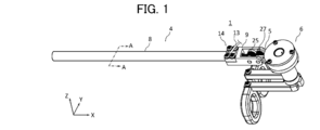
- FIG. 1 is a perspective view of the catheter device according to the embodiment.
- FIG. 2 is a cross-sectional view thereof.
- the illustrated X-axis, Y-axis, and Z-axis are appropriately used. Further, the directions of the X-axis, the Y-axis, and the Z-axis in each figure are basically the same.
- the positive direction of the X-axis indicates the proximal end side, and the opposite indicates the distal end side.
- the Z-axis direction is the vertical direction
- the X-axis is the longitudinal direction
- the Y-axis is the longitudinal direction. It is an orthogonal short direction. Therefore, the Z-axis direction may be referred to as a vertical direction
- the Y-axis direction may be referred to as a left-right direction or a lateral direction.
- the catheter device 1 is an example of a long medical device, for example, a minimally invasive surgical instrument that is guided to a predetermined site in the heart through a blood vessel to perform a predetermined procedure.
- the catheter device 1 includes a main body portion 4, a pulley fixing portion 9, a connecting portion 5, and an operating portion 6.
- the portion (tip portion) on the tip end side of the main body portion 4 can be bent up and down and bent left and right.
- the main body portion 4 is an example of a bent portion, and includes a shaft 8 and a metal ring 10.
- the shaft 8 may be made of, for example, a synthetic resin or the like.
- the metal ring 10 is a metal ring-shaped member, and is connected to the tip of the shaft 8.
- the pulley fixing portion 9 is connected to the base end side of the shaft 8.
- the connecting portion 5 connects the operating portion 6 to the pulley fixing portion 9 so as to be rotatable in the vertical direction.
- the operation unit 6 can rotate in the vertical direction about the rotation axis of the pulley unit 27.
- the operation unit 6 is a portion for a user (for example, a surgeon) to operate the tip side of the main body unit 4 in order to perform a vertical bending operation and a left / right bending operation.
- FIG. 3 is a cross-sectional view of the main body of the catheter device, and shows a cross-sectional view taken along the line AA shown in FIG.
- a lumen (lumen, passage) 12A to 12D for inserting a plurality of (four in this example) wire ropes (an example of an operation line), and the main body 4
- a device used for treatment on the tip side and a treatment lumen 11 for supplying a chemical solution to the tip side are arranged.
- the wire rope 20A is inserted into the lumen 12A
- the wire rope 20B is inserted into the lumen 12B
- the wire rope 20C is inserted into the lumen 12C
- the wire rope 20D is inserted into the lumen 12D.
- the lumens 12A to 12D may be configured by a tube.
- the treatment lumen 11 is formed by a tube 13.
- FIG. 4 is a front view of the tip portion of the catheter device.
- a metal ring 10 is connected to a shaft 8 at the tip of the main body 4. According to the metal ring 10, the tip side of the lumens 12A to 12D is sealed, while the tip side of the treatment lumen 11 is open.
- Wire ropes 20A to 20D are connected to the metal ring 10. As a method of connecting the wire ropes 20A to 20D to the metal ring 10, for example, welding may be performed or bonding may be performed.
- the wire ropes 20A and 20D are at the same height position (lower side) in the Z-axis direction in the metal ring 10 when the treatment lumen 11 is centered in the front view of the tip portion of the main body portion 4.
- the wire ropes 20B and 20C are connected to the same height position (upper side) in the Z-axis direction. That is, the wire ropes 20A and 20D and the wire ropes 20B and 20C are connected at intervals in the Z-axis direction (an example of the first direction).
- the wire ropes 20A and 20B are connected to the same position (left side) in the Y-axis direction in the metal ring 10, and the wire ropes 20C and 20D are connected to the same position (right side) in the Y-axis direction. That is, the wire ropes 20A and 20B and the wire ropes 20C and 20D are connected at intervals in the Y-axis direction (an example of the second direction) intersecting the Z-axis.
- FIG. 5A and 5B are schematic configuration views of the catheter device, FIG. 5A is a top view thereof, FIG. 5B is a side view of the catheter device facing the Y-axis direction, and FIG. 5C is an X-axis view. It is a side view from a direction.
- the pulley portion 25 and the pulley portion 27 are rotatably supported around the rotating shafts 31 and 33, respectively.
- the rotation axis of the pulley portion 25 and the pulley portion 27 is an axis parallel to the Y axis, and the rotation plane is an XX plane (vertical plane).
- an opening 14 for leading out the tube 13 communicating with the treatment lumen 11 of the main body portion 4 upward is formed.
- the pulley portion 25 has four pulleys 26A to 26D.
- the pulleys 26A to 26D are disk-shaped members having a groove portion formed on the outer periphery of the pulley to which a wire rope can be hung, and can rotate independently about the rotation shaft 31.
- the rotary shaft 31 is a non-rotatable fixed shaft, and the pulleys 26A to 26D are rotatable with respect to the rotary shaft 31.
- the pulleys 26A to 26D may be made of, for example, medical stainless steel.
- the pulley portion 27 has four pulleys 28A to 28D.
- the pulleys 28A to 28D are disk-shaped members having a groove formed on the outer periphery on which a wire rope can be hung, and can rotate independently about the rotation shaft 33.
- the rotary shaft 33 is a non-rotatable fixed shaft, and the pulleys 28A to 28D are rotatable with respect to the rotary shaft 33.
- the pulleys 28A to 28D may be made of, for example, medical stainless steel.
- the diameters (pulley diameters) of the pulleys 26A to 26D and 28A to 28D are, for example, 9 mm.
- FIG. 6 is a cross-sectional view of the operation unit of the catheter device.
- the operation unit 6 includes a base end side pulley (drive side pulley) 40, 41, a solid shaft 42 and a hollow shaft 43 as an example of the operation shaft, bearings 44, 45, and keys 46, 47, 50, 51. , With finger hooks 48, 49.
- the base end side pulleys 40 and 41 are disk-shaped members having a groove portion formed on the outer periphery of the pulley so that a wire rope can be hung on the outer periphery thereof, and can rotate independently about the operation shaft.
- the proximal end side pulley 40 is above the proximal end side pulley 41 (plus direction of the Z axis).
- Their rotation axes are common to the axis parallel to the Z axis (vertical axis), and the rotation plane is the XY plane (horizontal plane).
- the rotation axis of the proximal end side pulleys 40 and 41 is perpendicular to the rotation axis 33 of the pulley unit 27, in other words.
- the rotating surface of the base end side pulleys 40 and 41 is perpendicular to the rotating surface of the pulley portion 27.
- the proximal end side pulley 40 and the proximal end side pulley 41 may be made of, for example, medical stainless steel.
- Two lines of wire ropes 20A and 20D are hung on the groove portion of the base end side pulley 40, and one end of each of the two lines of wire rope is fixed.
- Two lines of wire ropes 20B and 20C are hung on the groove portion of the base end side pulley 41, and one end of each of the two lines of wire rope is fixed.
- the wire ropes 20A to 20D are formed by, for example, twisting a plurality of wires (wires).
- the finger hooks 48 and 49 are the parts where one finger of one hand of the user of the catheter device 1 is inserted and the driving force for operating the catheter device 1 is applied.
- the finger hooks 48 and 49 are configured to be located at a position distant from the tip side with respect to the operation axis in the reference state.
- the solid shaft 42 is inserted into the hollow portion of the hollow shaft 43, and is rotatably provided on the inner circumference of the hollow shaft 43 via bearings 44 and 45.
- the base end side pulley 40 is fixed to the solid shaft 42 by the key 46, and can rotate integrally with the solid shaft 42.
- the base end side pulley 41 is fixed to the hollow shaft 43 by the key 47, and can rotate integrally with the hollow shaft 43.
- the finger hook 48 is fixed to the hollow shaft 43 by the key 50 and can rotate integrally with the hollow shaft 43.
- the finger hook 49 is fixed to the solid shaft 42 by the key 51 and can rotate integrally with the solid shaft 42. Therefore, when the user rotates the finger hook 48, the proximal end side pulley 41 rotates in the same direction, and when the user rotates the finger hook 49, the proximal end side pulley 40 rotates in the same direction. ..
- the finger hooks 48 and 49 are located away from the drive shafts (solid shaft 42 and hollow shaft 43), the base end side pulleys 40 and 41 can be rotated by a relatively small force. can.
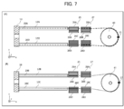
- FIG. 7A shows the wiring of the wire rope between the metal ring 10 and the proximal end side pulley 40
- FIG. 7B shows the arrangement of the wire rope between the metal ring 10 and the proximal end.
- the wiring of the wire rope to and from the side pulley 41 is shown.
- one end of the wire rope 20A is connected to the position on the positive side of the Y axis of the metal ring 10 at the tip of the main body 4.
- the wire rope 20A is hung from the metal ring 10 through the lumen 12A to the proximal end side pulley 40 via the groove on the lower side of the pulley 26A and the groove on the upper side of the pulley 28A.
- the other end of the wire rope 20A is fixed by the fixing member 15.
- One end of the wire rope 20D is connected to the position on the minus side of the Y axis of the metal ring 10 at the tip of the main body 4.
- the wire rope 20D runs from the metal ring 10 through the lumen 12D to the proximal end pulley 40 via the groove on the lower side of the pulley 26D and the groove on the upper side of the pulley 28D.
- the other end of the wire rope 20D is fixed by the fixing member 15.
- one end of the wire rope 20B is connected to the position on the positive side of the Y axis of the metal ring 10 at the tip of the main body 4.
- the wire rope 20B runs from the metal ring 10 through the lumen 12B to the proximal end pulley 41 via the groove on the upper side of the pulley 26B and the groove on the lower side of the pulley 28A.
- the other end of the wire rope 20B is fixed by the fixing member 17.
- One end of the wire rope 20C is connected to the position on the minus side of the Y axis of the metal ring 10 at the tip of the main body 4.
- the wire rope 20C is passed from the metal ring 10 through the lumen 12C to the proximal end side pulley 41 via the groove on the upper side of the pulley 26C and the groove on the upper side of the pulley 28C.
- the other end of the wire rope 20C is fixed by the fixing member 17.
- FIG. 8 is a diagram illustrating a vertical bending operation of the catheter device.
- the side (lower side) can be easily moved in the direction away from the base end side. As a result, the tip of the main body 8 is bent upward. Since each of the wire ropes 20A to D is inserted into the lumens 12A to 12D and the position is restricted, the wire ropes 20A to D do not adversely affect the surrounding parts in the shaft 8.
- the operation unit 6 itself in order to bend the tip end side of the main body 4 upward or downward, the operation unit 6 itself may be rotated, so that the operation unit 6 itself may be bent by the force of a fingertip as compared with the case of bending. A relatively large force can be easily applied, and the tip end side of the main body 4 can be easily bent upward or downward.
- FIG. 9 is a diagram illustrating a lateral bending motion of the catheter device.
- the proximal end side pulley 41 is rotated counterclockwise with respect to the metal ring 10 connected via the wire ropes 20B and 20C.
- a force for bending around is applied, and as a result, the tip of the main body 4 bends in the negative direction of the Y axis, while when the finger hook 48 is rotated clockwise, the base end side pulley 41 turns clockwise.
- a force that moves and bends the metal ring 10 connected via the wire ropes 20B and 20C in a clockwise direction is applied, and as a result, the tip end portion of the main body portion 4 bends in the positive direction of the Y axis.
- the finger hook 48 and the finger hook 49 are moved in the same direction, a force for rotating the tip portion of the main body portion 4 in the same direction is applied, and a lateral bending motion can be realized.
- the tip portion of the main body portion 4 can be bent in the negative direction of the Y axis as shown in FIG.
- the tip portion of the main body portion 4 can be bent in the positive direction of the Y axis.
- the four wire ropes (20A, 20B, 20C, 20D) can realize the vertical bending operation and the lateral bending operation of the tip portion of the main body portion 4. Further, by combining the operation on the operation unit 6 in the vertical bending operation and the operation on the operating unit 6 in the lateral bending operation, it is possible to realize a bending operation in which the vertical bending operation and the lateral bending operation are combined.
- FIG. 10 is a perspective view thereof
- FIG. 11 is a cross-sectional view.
- the same parts as those of the catheter device according to the above embodiment are designated by the same reference numerals, and redundant description will be omitted.
- the tube 13 communicating with the treatment lumen 11 is led out from the opening 14 of the pulley fixing portion 9, and the main body portion 4 is used. It is a device that can be derived from the extension of the central axis of.
- the tube 13 can be led out to the proximal end side from the through hole 52 formed in the operating portion 6.
- FIG. 12A and 12B are schematic configuration views of the catheter device, FIG. 12A is a top view thereof, FIG. 12B is a side view of the catheter device facing the Y-axis direction, and FIG. 12C is an X-axis view. It is a side view from a direction.
- a through hole 32 (first through hole) through which the tube 13 can be conducted is formed on the rotation shaft 31 of the pulley portion 25 on an extension line of the central axis of the main body portion 4. Further, the rotating shaft 32 of the pulley portion 27 is formed with a through hole 34 (first through hole) through which the tube 13 can be conducted, on an extension line of the central axis of the main body portion 4. Further, a through hole 52 (second through hole) capable of conducting the tube 13 is formed on the extension line of the central axis of the main body portion 4 of the operation portion 6.
- FIG. 13 is a cross-sectional view of the operation unit of the catheter device.
- a through hole 52 extending on an extension line of the central shaft of the main body portion 4 is formed in the drive shaft portion between the proximal end side pulley 40 and the proximal end side pulley 41.
- the maximum diameter of the through hole 52 on the base end side is larger than the maximum diameter on the tip end side.
- the drive shaft (solid shaft 42, hollow shaft 43) of the operation unit 6 is rotated or moved in the vertical direction by the user's operation.
- the through hole 52 also rotates or moves in the vertical direction as the drive shaft moves.
- the moving range of the through hole 52 becomes wider toward the proximal end side.
- the through hole 52 has a wide moving range, and the maximum diameter on the proximal end side is larger than the maximum diameter on the distal end side. Therefore, the operation unit 6 is rotated or moved. In this case, it is possible to reduce the situation where the outer peripheral portion of the through hole 52 comes into contact with the tube 13 and bends the tube 13.
- wire ropes 20A, 20B, 20C, and 20D are separated from each other, that is, four wire ropes are used, but the present invention is not limited to this. Instead, for example, two wire ropes attached to each of the same base end side pulleys 40 and 41 may be configured as one wire rope.
- the wire rope is arranged so that the tip end side of the main body 4 is bent upward when the operation portion 6 is bent upward.
- the wire rope may be arranged so that the tip portion of the main body portion 4 is bent downward. ..
- the pulleys of the pulley portion were independently rotatable about the center of the rotation axis, but the present invention is not limited to this, and at least a part of the pulleys may be non-rotatable.
- the groove portion of the pulley that does not rotate may be made of a member having a low frictional resistance in which the wire rope easily slides.
- a wire rope was used as the operation line, a wire may be used instead of the wire rope, or an elastic string member may be used.
- the shaft 8 of the main body 4 is provided with one treatment lumen, but the present invention is not limited to this, and a plurality of treatment lumens may be provided.
- the rotation surface of the base end side pulley and the pulley portion provided on the rotation shaft for rotating the base end side pulley in the vertical direction is configured to be vertical, but the present invention is not limited to this, and these The rotating surfaces may be configured to intersect at any angle other than 90 degrees.
- the catheter device has been described as an example of a long medical device, but the present invention is not limited to this, and any long medical device may be used, for example, an endoscope or the like having a bendable portion at the tip. ..
Landscapes
- Health & Medical Sciences (AREA)
- Life Sciences & Earth Sciences (AREA)
- Engineering & Computer Science (AREA)
- Anesthesiology (AREA)
- Biophysics (AREA)
- Pulmonology (AREA)
- Biomedical Technology (AREA)
- Heart & Thoracic Surgery (AREA)
- Hematology (AREA)
- Animal Behavior & Ethology (AREA)
- General Health & Medical Sciences (AREA)
- Public Health (AREA)
- Veterinary Medicine (AREA)
- Mechanical Engineering (AREA)
- Media Introduction/Drainage Providing Device (AREA)
Priority Applications (5)
| Application Number | Priority Date | Filing Date | Title |
|---|---|---|---|
| PCT/JP2020/023859 WO2021255877A1 (ja) | 2020-06-17 | 2020-06-17 | 長尺状医療用装置 |
| JP2022531183A JPWO2021255877A1 (https=) | 2020-06-17 | 2020-06-17 | |
| EP20941357.4A EP4169563A4 (en) | 2020-06-17 | 2020-06-17 | ELONGATED MEDICAL DEVICE |
| CN202080102077.3A CN115916318A (zh) | 2020-06-17 | 2020-06-17 | 长条状医疗用装置 |
| US18/082,845 US20230121016A1 (en) | 2020-06-17 | 2022-12-16 | Elongated medical device |
Applications Claiming Priority (1)
| Application Number | Priority Date | Filing Date | Title |
|---|---|---|---|
| PCT/JP2020/023859 WO2021255877A1 (ja) | 2020-06-17 | 2020-06-17 | 長尺状医療用装置 |
Related Child Applications (1)
| Application Number | Title | Priority Date | Filing Date |
|---|---|---|---|
| US18/082,845 Continuation US20230121016A1 (en) | 2020-06-17 | 2022-12-16 | Elongated medical device |
Publications (1)
| Publication Number | Publication Date |
|---|---|
| WO2021255877A1 true WO2021255877A1 (ja) | 2021-12-23 |
Family
ID=79267669
Family Applications (1)
| Application Number | Title | Priority Date | Filing Date |
|---|---|---|---|
| PCT/JP2020/023859 Ceased WO2021255877A1 (ja) | 2020-06-17 | 2020-06-17 | 長尺状医療用装置 |
Country Status (5)
| Country | Link |
|---|---|
| US (1) | US20230121016A1 (https=) |
| EP (1) | EP4169563A4 (https=) |
| JP (1) | JPWO2021255877A1 (https=) |
| CN (1) | CN115916318A (https=) |
| WO (1) | WO2021255877A1 (https=) |
Families Citing this family (1)
| Publication number | Priority date | Publication date | Assignee | Title |
|---|---|---|---|---|
| CN114555172B (zh) * | 2019-10-23 | 2023-08-01 | 朝日英达科株式会社 | 丝材送出装置 |
Citations (7)
| Publication number | Priority date | Publication date | Assignee | Title |
|---|---|---|---|---|
| JP2000139944A (ja) * | 1998-11-10 | 2000-05-23 | Olympus Optical Co Ltd | 高周波処置具 |
| JP2010094484A (ja) | 2008-10-20 | 2010-04-30 | River Seiko:Kk | カテーテルの湾曲操作装置 |
| JP2012050538A (ja) * | 2010-08-31 | 2012-03-15 | Terumo Corp | アブレーションデバイス |
| JP3179789U (ja) * | 2012-09-07 | 2012-11-15 | 日本ベルパーツ株式会社 | 先端操作機構 |
| JP2015506724A (ja) * | 2011-11-23 | 2015-03-05 | リブスメド インコーポレーテッド | 差動部材 |
| JP2016002226A (ja) * | 2014-06-17 | 2016-01-12 | オリンパス株式会社 | ガイド装置および手術システム |
| JP2018518276A (ja) * | 2015-06-10 | 2018-07-12 | デジタル エンドスコピー ゲーエムベーハー | 偏向移動伝達装置、内視鏡湾曲制御装置、及び内視鏡 |
Family Cites Families (8)
| Publication number | Priority date | Publication date | Assignee | Title |
|---|---|---|---|---|
| WO1993020886A1 (en) * | 1992-04-13 | 1993-10-28 | Ep Technologies, Inc. | Articulated systems for cardiac ablation |
| JP5090045B2 (ja) * | 2007-04-03 | 2012-12-05 | テルモ株式会社 | マニピュレータ及びその制御方法 |
| US20130331826A1 (en) * | 2010-12-09 | 2013-12-12 | Agile Endosurgery, Inc. | Surgical instrument |
| US20130218005A1 (en) * | 2012-02-08 | 2013-08-22 | University Of Maryland, Baltimore | Minimally invasive neurosurgical intracranial robot system and method |
| EP3125738A4 (en) * | 2014-03-31 | 2017-12-06 | Human Extensions Ltd. | Steerable medical device |
| WO2015195277A1 (en) * | 2014-06-20 | 2015-12-23 | Cook Medical Technologies Llc | Mechanism of small drive wire retention on spool |
| KR102153407B1 (ko) * | 2015-02-17 | 2020-09-08 | 주식회사 리브스메드 | 수술용 인스트루먼트 |
| CA3035415A1 (en) * | 2016-05-23 | 2017-11-30 | Imperial Innovations Limited | Surgical instrument, robotic arm and control system for a robotic arm |
-
2020
- 2020-06-17 JP JP2022531183A patent/JPWO2021255877A1/ja active Pending
- 2020-06-17 WO PCT/JP2020/023859 patent/WO2021255877A1/ja not_active Ceased
- 2020-06-17 EP EP20941357.4A patent/EP4169563A4/en not_active Withdrawn
- 2020-06-17 CN CN202080102077.3A patent/CN115916318A/zh not_active Withdrawn
-
2022
- 2022-12-16 US US18/082,845 patent/US20230121016A1/en not_active Abandoned
Patent Citations (7)
| Publication number | Priority date | Publication date | Assignee | Title |
|---|---|---|---|---|
| JP2000139944A (ja) * | 1998-11-10 | 2000-05-23 | Olympus Optical Co Ltd | 高周波処置具 |
| JP2010094484A (ja) | 2008-10-20 | 2010-04-30 | River Seiko:Kk | カテーテルの湾曲操作装置 |
| JP2012050538A (ja) * | 2010-08-31 | 2012-03-15 | Terumo Corp | アブレーションデバイス |
| JP2015506724A (ja) * | 2011-11-23 | 2015-03-05 | リブスメド インコーポレーテッド | 差動部材 |
| JP3179789U (ja) * | 2012-09-07 | 2012-11-15 | 日本ベルパーツ株式会社 | 先端操作機構 |
| JP2016002226A (ja) * | 2014-06-17 | 2016-01-12 | オリンパス株式会社 | ガイド装置および手術システム |
| JP2018518276A (ja) * | 2015-06-10 | 2018-07-12 | デジタル エンドスコピー ゲーエムベーハー | 偏向移動伝達装置、内視鏡湾曲制御装置、及び内視鏡 |
Non-Patent Citations (1)
| Title |
|---|
| See also references of EP4169563A4 |
Also Published As
| Publication number | Publication date |
|---|---|
| CN115916318A (zh) | 2023-04-04 |
| JPWO2021255877A1 (https=) | 2021-12-23 |
| EP4169563A1 (en) | 2023-04-26 |
| US20230121016A1 (en) | 2023-04-20 |
| EP4169563A4 (en) | 2024-04-03 |
Similar Documents
| Publication | Publication Date | Title |
|---|---|---|
| CN107708597B (zh) | 手术用机器人 | |
| EP3321047A1 (en) | Surgical robot | |
| US7955321B2 (en) | Surgical operation apparatus and manipulator for use therein | |
| KR20220070334A (ko) | 다중 케이블 의료 기기 | |
| JP6153678B2 (ja) | マニピュレータ及びマニピュレータシステム | |
| JP6214464B2 (ja) | 内視鏡システム | |
| US20190159852A1 (en) | Surgical tool, medical treatment instrument, and surgical system | |
| EP3321046A1 (en) | Slewing device and surgical instrument | |
| JP6296869B2 (ja) | 処置具および手術システム | |
| US20210228296A1 (en) | Bimanual neuroendoscopic robot | |
| KR20110100990A (ko) | 수술용 인스트루먼트 | |
| US20170071458A1 (en) | Guiding device and surgical system | |
| JP2015130898A (ja) | 操作部材 | |
| US20230121016A1 (en) | Elongated medical device | |
| JPWO2017126100A1 (ja) | 医療器具 | |
| CN116492020A (zh) | 一种手术器械组件、装置及机器人 | |
| CN116250930A (zh) | 一种手术钳末端控制装置 | |
| JP2023517285A (ja) | 内視鏡手術器具用エンドエフェクタ | |
| CN114129228B (zh) | 手术执行器 | |
| CN222853979U (zh) | 手术器械及医疗系统 | |
| US9345863B2 (en) | Bending operation member, and medical apparatus | |
| CN222870639U (zh) | 手术器械及医疗系统 | |
| CN116919484A (zh) | 一种末端执行机构、手术器械及手术机器人 | |
| CN119488324A (zh) | 柔性臂、器械杆及手术设备 | |
| CN115211975A (zh) | 一种用于手术机器人的内窥镜连续体装置 |
Legal Events
| Date | Code | Title | Description |
|---|---|---|---|
| 121 | Ep: the epo has been informed by wipo that ep was designated in this application |
Ref document number: 20941357 Country of ref document: EP Kind code of ref document: A1 |
|
| ENP | Entry into the national phase |
Ref document number: 2022531183 Country of ref document: JP Kind code of ref document: A |
|
| NENP | Non-entry into the national phase |
Ref country code: DE |
|
| ENP | Entry into the national phase |
Ref document number: 2020941357 Country of ref document: EP Effective date: 20230117 |