WO2021250942A1 - マスク - Google Patents
マスク Download PDFInfo
- Publication number
- WO2021250942A1 WO2021250942A1 PCT/JP2021/004687 JP2021004687W WO2021250942A1 WO 2021250942 A1 WO2021250942 A1 WO 2021250942A1 JP 2021004687 W JP2021004687 W JP 2021004687W WO 2021250942 A1 WO2021250942 A1 WO 2021250942A1
- Authority
- WO
- WIPO (PCT)
- Prior art keywords
- main body
- opening
- cartridge
- cover member
- mask
- Prior art date
- Legal status (The legal status is an assumption and is not a legal conclusion. Google has not performed a legal analysis and makes no representation as to the accuracy of the status listed.)
- Ceased
Links
Images










Classifications
-
- A—HUMAN NECESSITIES
- A41—WEARING APPAREL
- A41D—OUTERWEAR; PROTECTIVE GARMENTS; ACCESSORIES
- A41D13/00—Professional, industrial or sporting protective garments, e.g. surgeons' gowns or garments protecting against blows or punches
- A41D13/05—Professional, industrial or sporting protective garments, e.g. surgeons' gowns or garments protecting against blows or punches protecting only a particular body part
- A41D13/11—Protective face masks, e.g. for surgical use, or for use in foul atmospheres
-
- A—HUMAN NECESSITIES
- A62—LIFE-SAVING; FIRE-FIGHTING
- A62B—DEVICES, APPARATUS OR METHODS FOR LIFE-SAVING
- A62B18/00—Breathing masks or helmets, e.g. affording protection against chemical agents or for use at high altitudes or incorporating a pump or compressor for reducing the inhalation effort
- A62B18/08—Component parts for gas-masks or gas-helmets, e.g. windows, straps, speech transmitters, signal-devices
Definitions
- the present invention relates to a mask.
- a mask has been proposed in which a cartridge having a filter is attached to and detached from the main body.
- the mask includes a cartridge, a face contact portion that contacts the face of the wearer wearing the mask, and a connector that connects the cartridge and the face contact portion.
- the wearer can use a clean filter (see Patent Document 1).
- the present invention has been made to solve the above problems, and an object of the present invention is to provide a mask capable of preventing the cartridge from becoming dirty or damaged.
- the mask according to the present invention is a mask to which a cartridge having a filter can be attached, and has a main body having a through hole and having a first opening and a second opening at both ends in the axial direction in which the through hole extends. It has a portion and a through hole, and has a first opening and a second opening at both ends in the axial direction in which the through hole extends, and the peripheral edge of the first opening is the second opening of the main body portion. It is provided with a contact portion fixed to the peripheral edge of the portion and capable of contacting the wearer's face, and a cover member attached so as to close the first opening of the main body portion and having at least one vent formed.
- a storage space for accommodating the cartridge is formed between the first opening of the main body and the cover member so as to close the through hole of the main body.
- a storage space that can accommodate a cartridge is formed between the main body and the cover member. Therefore, since the housed cartridge is protected by the main body portion and the cover member, it is possible to prevent the cartridge from becoming dirty or damaged except by filtering air.
- the main body portion can be provided with a support surface formed along the inner circumference of the through hole of the main body portion, and the peripheral edge portion of the cartridge is the support surface of the main body portion and the cover. It can be configured to be sandwiched by members.
- the cartridge since the peripheral edge of the cartridge is sandwiched between the cover member and the support surface of the main body, the cartridge can be firmly attached to the main body. Therefore, it is possible to suppress the formation of a gap between the cartridge and the through hole of the main body portion, and it is possible to prevent the exhaled air and the inspiratory air of the wearer from leaking from other than the filter.
- the cover member is connected to the front wall portion on which the ventilation hole is formed and the peripheral edge of the front wall portion, and is detachably fixed to the peripheral edge of the first opening portion of the main body portion. And can be provided, and a gap can be formed between the front wall portion and the filter.
- a gap is formed between the attached cartridge and the front wall portion of the cover member. Therefore, for example, even if filth such as liquid invades through the ventilation hole of the front wall portion, the gap causes the gap. It can be suppressed from reaching the cartridge.
- the cover member can be fixed to the peripheral edge of the first opening of the main body by screwing.
- the cover member it is easy to attach the cover member. Further, for example, when the peripheral edge of the cartridge is configured to be sandwiched between the cover member and the support surface of the main body, the peripheral edge of the cartridge can be strongly pressed by screwing the cover member, so that the cartridge can be pressed. Further, it can be brought into close contact with the support surface even more strongly.
- the contact portion protrudes from the main body portion, and the thickness of the contact portion can be made smaller than the thickness of the main body portion.
- the cartridge can be firmly supported by increasing the thickness of the main body.
- the thickness of the contact portion it becomes easy to be deformed, so that the load on the wearer's face can be reduced.
- the contact portion may have a tapered portion or a wedge-shaped portion whose thickness decreases toward the second opening.
- the load on the face can be reduced by reducing the thickness.
- the strength can be increased by increasing the thickness.
- the end portion of the contact portion on the second opening side can be formed so as to extend so as to bend inward in the radial direction of the through hole of the contact portion.
- the contact portion can be brought into contact with the wearer's face as a surface at the time of wearing, it is possible to prevent high pressure from acting on the face.
- the other mask according to the present invention is a mask to which a cartridge having a filter can be detachably attached, and is provided on the main body portion to which the cartridge is attached and on the rear side of the main body portion and comes into contact with the wearer's face. It is provided with a contact portion, and the main body portion and the contact portion are integrally molded.
- the mask according to the present invention it is possible to prevent the cartridge from becoming dirty or damaged.
- FIG. 6 is a cross-sectional view of FIG. , Is a perspective view of the contact portion viewed from the front.
- 9 is a perspective view of the contact portion of FIG. 9 as viewed from the rear. 9 is a vertical cross-sectional view of FIG.
- FIG. 9 is a cross-sectional view of FIG. It is a perspective view of a cover member.
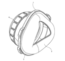
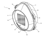
- FIG. 1 is a perspective view of the mask according to the present embodiment as viewed from the front
- FIG. 2 is a perspective view of the mask of FIG. 1 as viewed from the rear
- FIG. 3 is a front view of FIG. 1
- FIG. 4 is a rear view of FIG.
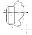
- FIG. 5 is a cross-sectional view of FIG.
- the direction in which the through holes of the main body portion and the contact portion extend may be referred to as an axial direction
- the direction orthogonal to this axial direction may be referred to as a radial direction.
- the present invention is not limited to these directions.
- this mask has a main body portion 1 having a through hole 10 and having a first opening portion 11 and a second opening portion 12 at both ends, and a first opening portion of the main body portion 1.
- a cover member 4 that is detachably attached so as to close 11 and a contact portion 2 that is fixed to the peripheral edge of the second opening 12 of the main body portion 1 and comes into contact with the wearer's face, and the rear of the flange 24 of the contact portion 2.
- a ring member 3 for holding the side is provided.
- the cartridge 5 is detachably housed in the storage space 100 formed by the main body 1 and the cover member 4.
- each member will be described in detail.
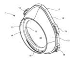
- Main body> 6 is a perspective view of the main body as seen from the front
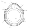
- FIG. 7 is a rear view of FIG. 6
- FIG. 8 is a sectional view of FIG.
- the main body 1 has a through hole 10 extending in the front-rear direction, and has a first opening 11 and a second opening 12 at both ends before and after the through hole 10, respectively.
- the first opening 11 is formed in a circular shape, but the second opening 12 is larger than the first opening 11 and is formed in a drop shape having an upper end projecting upward. That is, as shown in FIG.
- the lower end and both sides of the second opening 12 are formed in an arc shape concentric with the first opening 11, but the upper end 111 protrudes upward and the radius of curvature of the inner edge is small. It has become. Then, as will be described later, the wearer's nose is accommodated on the upper end side.
- the side surface 13 of the main body 1 has a second opening from the peripheral edge of the first opening 11. It is formed by a curved surface that gently spreads toward the periphery of the twelve.
- a cylindrical inner wall surface 14 having a short axial length is formed, and a flange 15 extending inward in the radial direction is formed at the lower end thereof.
- a female screw 16 for attaching the cover member 4 is formed on the inner wall surface 14, as will be described later.
- the front surface of the flange 15 corresponds to the support surface of the present invention.
- a step portion 17 extending outward in the radial direction and an extending portion 18 extending rearward from the step portion 17 are provided at the end of the side surface 13 of the main body 1 on the side of the second opening 12.
- the space surrounded by the extending portion 18 forms the second opening 12.
- the flange 24 at the front end of the contact portion 2 is accommodated in the space having a rectangular cross section formed by the step portion 17 and the extending portion 18.
- a plurality of insertion portions 19 having through holes extending in the front-rear direction are provided on the outer surface of the extending portion 18. More specifically, two insertion portions 19 are formed on the right side of the extending portion 18 at predetermined intervals in the vertical direction, and two insertion portions 19 are formed on the left side of the extending portion 18 at predetermined intervals in the vertical direction. It is formed at the same time. That is, the two insertion portions 19 on the right side and the two insertion portions 19 on the left side are provided so as to be symmetrical. Then, as will be described later, the string 30 is inserted into the through holes of the insertion portions 19.
- the main body 1 is integrally formed of a resin material or the like so as to have the above-mentioned portion.
- the resin material is preferably a resin material that can be washed and sterilized and can withstand repeated use, for example, a polypropylene resin, a polyethylene resin, a polyurethane resin, a polyamide synthetic resin, an unsaturated polyester resin material, a silicone resin material, or a resin material.
- a urea resin material or the like can be adopted.
- FIG. 9 is a perspective view of the contact portion viewed from the front
- FIG. 10 is a perspective view of the contact portion of FIG. 9 viewed from the rear
- FIG. 11 is a vertical sectional view of FIG. 9
- FIG. 12 is a cross-sectional view of FIG. be.
- the contact portion 2 is designed to correspond to the surface shape of the wearer's face.
- the contact portion 2 has a through hole 20 extending in the front-rear direction, and has a first opening portion 21 and a second opening portion 22 at both ends thereof before and after the contact portion 2, respectively.
- a flange 24 extending radially outward is formed at the edge of the first opening 21, and the flange 24 is formed in a shape corresponding to the second opening 12 of the main body 1. As will be described later, the flange 24 is arranged on the rear surface of the step portion 17 of the main body portion 1. However, the width of the flange 24 is narrower than the width of the step portion 17.
- the side surface 23 of the contact portion 2 includes a first portion 231 extending rearward from the first opening 21 and a second portion 232 bent in an arc shape from the rear end of the first portion 231 and extending inward in the radial direction. have.
- the space surrounded by the inner edge of the second portion 232 forms the second opening 22. Since the second portion 232 protrudes inward in the radial direction and the second portion 232 comes into contact with the wearer's face as a surface, it is possible to suppress the action of high pressure on the face. Further, as will be described later, since the contact portion 2 is made of a relatively soft material that is easily deformed, it is easily deformed along the shape of the wearer's face. As described above, the shape of the contact portion 2 comes into contact with the surface of the wearer's face, and is therefore an important shape for realizing the function of the mask.
- the central portion in the left-right direction in the upper part of the second portion 232 is recessed toward the front.
- the central portion in the left-right direction at the lower portion of the second portion 232 is recessed toward the front.
- the upper part of the contact portion 2 comes into contact with the wearer's nose and the lower part comes into contact with the wearer's chin due to the elastic restoring force of the string 30 (see FIG. 21) made of an elastic member described later.
- the nose and chin project forward compared to the cheeks, and high pressure is likely to act when wearing a mask. Therefore, by denting the upper part and the lower part of the contact portion 2 toward the front, it is possible to suppress the action of high pressure on the nose and chin.
- the upper portion and the lower portion of the second portion 232 are curved so as to be involved in the front side and inward in the radial direction. By bending in this way, the shape corresponds to the nose and chin, and it becomes easy to adhere to the nose and chin.
- the left and right parts of the second part 232 come into contact with the wearer's cheeks.
- the left and right portions of the second portion 232 are not caught forward as much as the upper and lower portions, and are radially inward in a direction substantially perpendicular to the axial direction of the through hole. It is extended. Therefore, since the rear surface of the second site 232 is in contact with the wearer's cheek almost entirely, the pressure acting on the cheek can be reduced as compared with the case where the trailing edge of the second site 232 is in contact.
- the second part 232 can be easily attached to the cheek.
- the thickness of the first portion 231 side of the contact portion 2 is d1
- the thickness of the tip end side (in other words, the rear end side of the contact portion 2) of the second portion 232 is d2.
- d2 ⁇ d1.
- the contact portion 2 has a tapered shape or a wedge shape in which the thickness on the rear end side is smaller than the thickness on the front end side (first opening 21 side), and gradually decreases toward the rear end side. That is, the contact portion 2 has a tapered portion or a wedge portion. Since the portion near the rear end side of the contact portion 2 (for example, the second portion 232) easily comes into contact with the face when worn, the thickness is reduced to reduce the load on the face.
- the thicknesses d1 and d2 described above depend on the material forming the contact portion 2, but for example, as long as d2 ⁇ d1, d1 is 1.0 to 8.0 mm and d2 is 0.5 to 4.0 mm. More preferably, d1 can be 1.5 to 6.0 mm and d2 can be 0.5 mm to 3.0 mm.
- the contact portion 2 may be formed in a tapered shape or a wedge shape as a whole, or may be partially formed in a tapered shape or a wedge shape, for example, only in the second portion 232.
- the thickness of the contact portion 2 can be at least partially smaller than the thickness of the main body portion 1.
- the thickness of the contact portion 2 may be made smaller than that of the main body portion 1 as a whole, or only the thickness of the second portion 232 may be made smaller than that of the main body portion 1.
- the material constituting the contact portion 2 is not particularly limited, but it is preferably a material that has flexibility and is easily deformed at the time of mounting.
- the main body 1 is preferably made of a material that is not easily deformed because it supports the cartridge and the cover member 4 is screwed, but the contact portion 2 is made of a material having a lower hardness than the main body 1. It is preferable to have.
- a material for example, a polyurethane resin, a polyamide resin, a silicone resin material such as silicone rubber, a fluororesin, an elastomer, or the like can be adopted.
- the ring member 3 is a thin plate-shaped member having a shape in a plan view substantially the same as the flange 24 of the contact portion 2. However, the width of the ring member 3 is slightly wider than that of the flange 24, and slightly extends outward in the radial direction from the flange 24. Further, the ring member 3 is integrally molded of the same material as the main body portion 1, and the flange 24 of the contact portion 2 is sandwiched between the step portion 17 of the main body portion 1 and the ring member 3.
- Cover member> 13 is a perspective view of the cover member
- FIG. 14 is a rear view of the cover member.
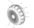
- the cover member 4 has a disk-shaped front wall portion 41, a cylindrical side wall portion 42 extending rearward from the peripheral edge of the front wall portion 41, and a rear end of the side wall portion 42. It is provided with a cylindrical connecting portion 43 extending rearward from the surface.
- a circular portion is formed in the vicinity of the center of the front wall portion 41, and a plurality of vent holes 411 arranged radially are formed around the circular portion.
- Each ventilation hole 411 is formed in a substantially arc shape, and by forming the ventilation hole 411 in an arc shape, it is difficult for the user to touch the cartridge, and ventilation can be appropriately performed.
- the width 411 of the ventilation hole is not particularly limited, but can be, for example, about 0.5 to 5 mm.
- the side wall portion 42 is formed so that its diameter increases toward the rear, and a substantially rectangular recess 421 arranged in the circumferential direction is formed on the outer surface thereof. These recesses 421 function as finger resting portions that play a role of preventing slipping when the cover member 4 is rotated by hand.
- the outer diameter of the connecting portion 43 is formed to be smaller than the outer diameter of the rear end of the side wall portion 42, and a male screw 431 is formed on the outer peripheral surface of the connecting portion 43.
- the male screw 431 is screwed into the female screw 16 of the main body 1.
- FIG. 15 is a perspective view of the cartridge
- FIG. 16 is a sectional view of the cartridge.
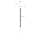
- the cartridge 5 includes a filter 51 formed in a rectangular shape and a fixing portion 52 connected to the outer periphery of the filter 51 and having a disk-shaped outer shape.
- the filter 51 can be, for example, a filter equivalent to the N95 standard, that is, a filter capable of collecting 95% or more of particles having an aerodynamic mass diameter of 0.3 ⁇ m in a collection efficiency test.
- the filter 51 is not limited to the filter corresponding to the N95 standard, and a filter equivalent to the N99, N100, R95, R99, R100, P95, P99 or P100 standard may be used.
- a filter equivalent to the N99, N100, R95, R99, R100, P95, P99 or P100 standard may be used.
- a HEPA (High Efficiency Particulate Air) filter can be used, but the filter 51 is not limited to this.
- the fixing portion 52 is formed of, for example, a resin material, and its outer diameter is substantially the same as the outer diameter of the flange 15 of the main body portion 1. Therefore, when the cartridge 5 is placed on the flange 15 of the main body 1, the peripheral edge of the fixing portion 52 is arranged on the flange 15 and the through hole 10 of the main body 1 extending in the front-rear direction can be closed.
- FIGS. 17 and 18 a method of assembling the mask formed as described above will be described with reference to FIGS. 17 and 18.
- the cartridge 5 is placed on the flange 15 of the main body 1.
- the cover member 4 is attached to the main body 1.
- the rear end portion of the connecting portion 43 of the cover member 4 is arranged on the fixing portion 52 of the cartridge 5, and the rear end portion of the connecting portion 43 sandwiches the fixing portion 52. It is arranged at a position facing the flange 15. Therefore, when the cover member 4 is screwed into the main body portion 1, the connecting portion 43 presses the fixing portion 52 of the cartridge 5 against the flange 15.
- the fixing portion 52 of the cartridge 5 is in close contact with the flange 15, and the through hole 10 of the main body portion 1 is closed by the cartridge 5. In this state, a gap is formed between the cartridge 5 and the front wall portion 41 of the cover member 4.
- the cover member 4 may be removed from the main body 1, and then the cartridge 5 may be replaced.
- a string 30 having an elastic force is inserted into the through hole of the insertion portion 19.
- the adjuster 31 is attached to the end of the string 30 extending from each of the two upper insertion portions 19.
- An adjuster 31 is also attached to the end of the string 30 extending from each of the two lower insertion portions 19.
- the string 30 and the adjuster 31 form two annular portions, and the wearer's head is inserted inside these two annular portions. The wearer can operate the adjuster 31 to adjust the size of the annular portion.
- sterilization methods include boiling sterilization, high-pressure steam sterilization (autoclave), ethylene oxide gas sterilization, radiation sterilization (gamma ray sterilization), ultraviolet sterilization, and sterilization with disinfectants such as formaldehyde. From the viewpoint of ensuring certainty, high-pressure steam sterilization (autoclave) is more preferable.
- the mask configured as described above has the following features. (1) Since the through hole 10 of the main body 1 is closed by the cartridge 5, the wearer's mouth and nose are passed through the filter 51 of the cartridge 5 and the ventilation hole 411 of the cover member 4 as shown by the arrow in FIG. , Communicate with the outside. Therefore, not only the inspiration of the wearer but also the exhalation of the wearer is filtered by the filter 51. Therefore, it is possible to prevent the wearer from sucking particles such as a virus from the outside. On the other hand, for example, even if the wearer is infected with a virus, the virus or the like contained in the exhaled breath can be captured by the filter 51. Therefore, it is possible to prevent the spread of virus infection.
- the cartridge 5 Since the cartridge 5 is covered with the cover member 4, for example, even if a liquid such as blood or a foreign substance adheres to the cover member 4 while the wearer is working, it is prevented from reaching the cartridge 5. be able to. Therefore, it is possible to prevent the performance of the filter 51 from being deteriorated due to the adhesion of foreign matter other than fine particles during the work.
- a gap is formed between the cartridge 5 housed in the storage space 100 and the front wall portion 41 of the cover member 4, it is possible to further prevent foreign matter from adhering to the cartridge 5.
- the fixing portion 52 of the cartridge 5 can be pressed against the flange 15 of the main body portion 1, so that the cartridge 5 can be firmly adhered to the main body portion 1. Therefore, it is possible to prevent exhaled air and inhaled air from passing through other than the filter 51.
- the contact portion 2 is formed as described above, it is possible to easily adhere to the wearer's face and prevent exhalation and inspiration from leaking from between the wearer's face and the contact portion 2. can do.
- the structure of the cartridge 5 is not particularly limited, and is configured to have a filter, be accommodated in the accommodation space 100 formed by the main body 1 and the cover member 4, and close the through hole 10 of the main body 1. It should be done. It is preferable that a gap is formed between the front wall portion 41 of the cover member 4 and the cartridge 5, but both may be in contact with each other. Therefore, the configuration of the filter 51 is not particularly limited, and a filter 51 that can capture particles according to the demand may be used. For example, the filters may be stacked in multiple layers.
- a plurality of types of cartridges may be manufactured by using a plurality of filters having different densities.
- the wearer can select a cartridge having an appropriate filter density corresponding to the usage environment.
- the color of the fixed portion in the cartridge may be different depending on the density of the filter. This is to prevent the wearer from selecting a cartridge having a filter density that does not correspond to the usage environment.
- the method of fixing the main body portion 1 and the contact portion 2 may be other than the above embodiment. Therefore, the main body portion 1 and the separate ring member 3 may be fixed by using an adhesive, and the flange 24 of the contact portion 2 may be sandwiched between them. Further, the main body portion 1 and the contact portion 2 can be directly fixed by an adhesive or welding without using the ring member 3.
- the main body portion 1 and the contact portion 2 can be integrally molded with the same resin material.
- the reinforcing rib 28 projecting outward in the radial direction is formed on the outer peripheral surface of the connecting portion between the main body portion 1 and the contact portion 2, and the thickness of the connecting portion is increased.
- reinforcing ribs are not always necessary.
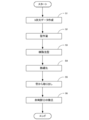
- FIG. 23 is a flowchart showing the manufacturing process of the mask main body.
- a mold for manufacturing the mask body is produced by a stereolithography method (S2). At this time, a mold characterized by the shape of the mask body shown in the above embodiment is produced.
- the raw material resin material is injected into the produced mold (S3).
- the resin material is not limited as long as it can be molded by curing the liquid, but a resin material that can be washed and sterilized and can withstand repeated use is preferable.
- a polyurethane resin material can be used.
- the material is not limited to the polyurethane resin material, and other resin materials such as unsaturated polyester resin material, polypropylene resin, polyethylene resin, fluororesin, elastomer, silicone resin material, and urea resin material may be used.
- the resin agent injected into the mold is cured (S4). It is cured by a curing method according to the resin material. For example, heat is applied to the resin material to cure it.
- the cured resin material is taken out from the mold (S5), the excess portion is removed (S6), and the mask body is manufactured.
- the main body portion 1 and the contact portion 2 are integrally molded with a resin material. Therefore, it is possible to prevent a gap from being generated between the main body portion 1 and the contact portion 2.
- a mold for manufacturing a mask body is manufactured by a stereolithography method, but the manufacturing method of this mold is an example, and a mold manufacturing method other than the stereolithography method is used. May be good. For example, it can be machined or electroformed.
- This mold may be a mold or a resin mold.
- the shape of the contact portion 2 of the above embodiment is an example, and the shape including the thickness is not particularly limited as long as it can be in close contact with the wearer's face. Further, the shape of the main body 1 is not particularly limited, and the outer shape is not particularly limited as long as it has a through hole 10.
- the cover member 4 is screwed to the main body 1, but the present invention is not limited to this, and if it can be detachably attached, a snap type or the like can be used. Fixing method can be adopted. Further, the shape of the cover member 4 is not particularly limited. Therefore, the shape of the accommodation space 100 of the cartridge 5 formed by the main body 1 and the cover member 4 may not be circular, and the outer shape of the cartridge 5 may be adjusted accordingly.
- the cartridge 5 is pressed against the flange 15 of the main body 1 by the cover member 4, and the through hole 10 of the main body 1 is airtightly closed. It can also be attached airtightly to the portion 1.
- the support surface of the present invention may be configured other than the flange 15, and may be configured so that the peripheral edge portion of the cartridge 5 is in contact with the support surface.
- the shape of the ventilation hole 411 provided in the cover member 4 is not particularly limited, and may be configured to allow exhalation and inspiration to pass through even if it is not the one shown in the above embodiment.
- the shape, number, and position of the insertion portion through which the string 30 is passed are not particularly limited, and may be appropriately changed depending on the type and application of the string to be used. Alternatively, the string 30 may be fixed to the mask body in advance.
- the cover member 4 is detachable, but the main body 1 may appear to be non-detachably fixed to the cover member 4. That is, once the cover member 4 is attached, the structure can be made non-removable. Similarly, the cartridge does not have to be removable, and once attached to the mask, it can be made non-removable.
Landscapes
- Health & Medical Sciences (AREA)
- General Health & Medical Sciences (AREA)
- Physical Education & Sports Medicine (AREA)
- Engineering & Computer Science (AREA)
- Textile Engineering (AREA)
- Pulmonology (AREA)
- Business, Economics & Management (AREA)
- Emergency Management (AREA)
- Respiratory Apparatuses And Protective Means (AREA)
Priority Applications (1)
| Application Number | Priority Date | Filing Date | Title |
|---|---|---|---|
| JP2022529373A JPWO2021250942A1 (https=) | 2020-06-09 | 2021-02-08 |
Applications Claiming Priority (2)
| Application Number | Priority Date | Filing Date | Title |
|---|---|---|---|
| JP2020100511 | 2020-06-09 | ||
| JP2020-100511 | 2020-06-09 |
Publications (1)
| Publication Number | Publication Date |
|---|---|
| WO2021250942A1 true WO2021250942A1 (ja) | 2021-12-16 |
Family
ID=78847184
Family Applications (1)
| Application Number | Title | Priority Date | Filing Date |
|---|---|---|---|
| PCT/JP2021/004687 Ceased WO2021250942A1 (ja) | 2020-06-09 | 2021-02-08 | マスク |
Country Status (2)
| Country | Link |
|---|---|
| JP (2) | JPWO2021250942A1 (https=) |
| WO (1) | WO2021250942A1 (https=) |
Citations (3)
| Publication number | Priority date | Publication date | Assignee | Title |
|---|---|---|---|---|
| JP2016528011A (ja) * | 2013-08-20 | 2016-09-15 | スリーエム イノベイティブ プロパティズ カンパニー | 個人用呼吸保護装置 |
| JP2016534764A (ja) * | 2013-09-24 | 2016-11-10 | スリーエム イノベイティブ プロパティズ カンパニー | 鼻支持拡張部を有する呼吸用マスク |
| JP2019044647A (ja) * | 2017-08-31 | 2019-03-22 | 山本光学株式会社 | ファンユニットおよびこのファンユニットを備えた呼吸用保護具 |
Family Cites Families (2)
| Publication number | Priority date | Publication date | Assignee | Title |
|---|---|---|---|---|
| JP2010220712A (ja) | 2009-03-23 | 2010-10-07 | Kyaribaa International Corporation:Kk | ウィルス遮断用マスク |
| TWM461442U (zh) | 2013-03-12 | 2013-09-11 | Yu-Hu Chen | 呼吸過濾裝置 |
-
2021
- 2021-02-08 JP JP2022529373A patent/JPWO2021250942A1/ja active Pending
- 2021-02-08 WO PCT/JP2021/004687 patent/WO2021250942A1/ja not_active Ceased
-
2023
- 2023-04-17 JP JP2023067450A patent/JP7709146B2/ja active Active
Patent Citations (3)
| Publication number | Priority date | Publication date | Assignee | Title |
|---|---|---|---|---|
| JP2016528011A (ja) * | 2013-08-20 | 2016-09-15 | スリーエム イノベイティブ プロパティズ カンパニー | 個人用呼吸保護装置 |
| JP2016534764A (ja) * | 2013-09-24 | 2016-11-10 | スリーエム イノベイティブ プロパティズ カンパニー | 鼻支持拡張部を有する呼吸用マスク |
| JP2019044647A (ja) * | 2017-08-31 | 2019-03-22 | 山本光学株式会社 | ファンユニットおよびこのファンユニットを備えた呼吸用保護具 |
Also Published As
| Publication number | Publication date |
|---|---|
| JP7709146B2 (ja) | 2025-07-16 |
| JPWO2021250942A1 (https=) | 2021-12-16 |
| JP2023099534A (ja) | 2023-07-13 |
Similar Documents
| Publication | Publication Date | Title |
|---|---|---|
| US10974084B1 (en) | Reusable respirator mask with refillable filter | |
| JP5160236B2 (ja) | 患者とのインターフェースのためのクッション及び患者とのインターフェース | |
| CN212395645U (zh) | 全面罩呼吸器、口鼻罩组件和全面罩呼吸器部件套装 | |
| US20210346733A1 (en) | Respirator having replaceable filtration medium | |
| JP6785919B2 (ja) | 呼吸保護マスク | |
| JP2021164659A (ja) | 音声伝達機能を備えた呼吸用マスク | |
| KR101434255B1 (ko) | 착용감이 향상된 코 마스크 | |
| JP6269144B2 (ja) | 顔面装着用マスク | |
| CN102665824A (zh) | 用于飞机机组人员的卫生面罩以及包括该卫生面罩的面罩组件 | |
| JP2018531104A6 (ja) | 音声伝達機能を備えた呼吸用マスク | |
| KR101915179B1 (ko) | 마스크 | |
| JP6382836B2 (ja) | 汎用クッションテンプレートを用いた呼吸インターフェースデバイスのカスタマイズ | |
| CN119403467A (zh) | 具有纹理接触部分和各种联接机构的高过滤可重复使用的口罩 | |
| JP6767378B2 (ja) | 端部出口を有する可撓性フィルタ要素 | |
| JP7709146B2 (ja) | マスク | |
| CN100577232C (zh) | 面罩系统 | |
| CN117460435A (zh) | 高过滤可重复使用的面罩 | |
| KR20200023348A (ko) | 방진용 마스크 및 그 제조방법 | |
| JPH1033910A (ja) | 反復使用可能なフィルタ枠体及びそれを使用した流体ろ過用フィルタ | |
| CN107079227A (zh) | 换能器保护系统、助听装置以及换能器保护系统的使用 | |
| US20200100037A1 (en) | Hearing device seal modules, modular hearing devices including the same and associated methods | |
| JP2006346166A (ja) | フィルタ部材 | |
| JP7755811B2 (ja) | マスクの面体用連結構造 | |
| KR20210143516A (ko) | 필터 교체형 보건 마스크 | |
| JP7506403B2 (ja) | 通気管路の連結機構 |
Legal Events
| Date | Code | Title | Description |
|---|---|---|---|
| 121 | Ep: the epo has been informed by wipo that ep was designated in this application |
Ref document number: 21822969 Country of ref document: EP Kind code of ref document: A1 |
|
| ENP | Entry into the national phase |
Ref document number: 2022529373 Country of ref document: JP Kind code of ref document: A |
|
| NENP | Non-entry into the national phase |
Ref country code: DE |
|
| 122 | Ep: pct application non-entry in european phase |
Ref document number: 21822969 Country of ref document: EP Kind code of ref document: A1 |