WO2021246282A1 - 空中表示装置 - Google Patents
空中表示装置 Download PDFInfo
- Publication number
- WO2021246282A1 WO2021246282A1 PCT/JP2021/020209 JP2021020209W WO2021246282A1 WO 2021246282 A1 WO2021246282 A1 WO 2021246282A1 JP 2021020209 W JP2021020209 W JP 2021020209W WO 2021246282 A1 WO2021246282 A1 WO 2021246282A1
- Authority
- WO
- WIPO (PCT)
- Prior art keywords
- display
- light
- aerial
- lens
- degrees
- Prior art date
Links
- 230000003287 optical effect Effects 0.000 claims description 64
- 238000010586 diagram Methods 0.000 description 41
- 238000004088 simulation Methods 0.000 description 27
- 239000000463 material Substances 0.000 description 8
- 230000015572 biosynthetic process Effects 0.000 description 6
- 230000000694 effects Effects 0.000 description 5
- 239000004973 liquid crystal related substance Substances 0.000 description 5
- 239000000470 constituent Substances 0.000 description 4
- 239000000758 substrate Substances 0.000 description 4
- 238000000034 method Methods 0.000 description 3
- 230000005540 biological transmission Effects 0.000 description 2
- 238000003384 imaging method Methods 0.000 description 2
- 239000005304 optical glass Substances 0.000 description 2
- 239000011347 resin Substances 0.000 description 2
- 229920005989 resin Polymers 0.000 description 2
- 239000004925 Acrylic resin Substances 0.000 description 1
- 229920000178 Acrylic resin Polymers 0.000 description 1
- 240000007594 Oryza sativa Species 0.000 description 1
- 235000007164 Oryza sativa Nutrition 0.000 description 1
- 230000004075 alteration Effects 0.000 description 1
- 230000002301 combined effect Effects 0.000 description 1
- 239000011159 matrix material Substances 0.000 description 1
- 230000004270 retinal projection Effects 0.000 description 1
- 235000009566 rice Nutrition 0.000 description 1
Images


Classifications
-
- G—PHYSICS
- G02—OPTICS
- G02B—OPTICAL ELEMENTS, SYSTEMS OR APPARATUS
- G02B30/00—Optical systems or apparatus for producing three-dimensional [3D] effects, e.g. stereoscopic images
- G02B30/60—Optical systems or apparatus for producing three-dimensional [3D] effects, e.g. stereoscopic images involving reflecting prisms and mirrors only
-
- G—PHYSICS
- G02—OPTICS
- G02B—OPTICAL ELEMENTS, SYSTEMS OR APPARATUS
- G02B30/00—Optical systems or apparatus for producing three-dimensional [3D] effects, e.g. stereoscopic images
- G02B30/50—Optical systems or apparatus for producing three-dimensional [3D] effects, e.g. stereoscopic images the image being built up from image elements distributed over a 3D volume, e.g. voxels
- G02B30/56—Optical systems or apparatus for producing three-dimensional [3D] effects, e.g. stereoscopic images the image being built up from image elements distributed over a 3D volume, e.g. voxels by projecting aerial or floating images
-
- G—PHYSICS
- G02—OPTICS
- G02B—OPTICAL ELEMENTS, SYSTEMS OR APPARATUS
- G02B27/00—Optical systems or apparatus not provided for by any of the groups G02B1/00 - G02B26/00, G02B30/00
- G02B27/0018—Optical systems or apparatus not provided for by any of the groups G02B1/00 - G02B26/00, G02B30/00 with means for preventing ghost images
Definitions
- the present invention relates to an aerial display device.
- the aerial display device uses, for example, a two-sided corner reflector array in which two-sided corner reflectors are arranged in an array to reflect light emitted from the display surface of a display element to form a real image in the air. ..
- the display method using the two-sided corner reflector array has no aberration, and a real image (hereinafter referred to as an aerial image) is displayed at a plane-symmetrical position.
- the present invention provides an aerial display device that ensures the display quality of an aerial image.
- the aerial display device of the embodiment according to the present invention has a display surface for displaying an image, and is arranged obliquely with respect to the display surface of the display unit and the display unit that emits display light from the display surface.
- a mirror device that reflects the display light emitted from the display unit and forms an aerial image at a position symmetrical to the display unit is provided, and the light distribution of the display light is a method of the display surface. It is larger than -35.0 degrees and less than +35.0 with the linear direction as 0 degrees.
- an aerial display device that ensures the display quality of an aerial image.
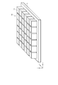
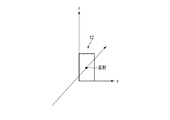
- FIG. 1 is a diagram schematically showing a configuration example of an aerial display device.
- FIG. 2 is a diagram schematically showing an example of a configuration of the mirror device shown in FIG. 1.
- FIG. 3 is a schematic diagram for explaining the principle of the aerial display device 1 of the embodiment.
- FIG. 4 is a schematic diagram illustrating an example of the state of light reflected twice by one optical element of the mirror device shown in FIG. 2.
- FIG. 5 is a diagram showing an optical path when the optical element shown in FIG. 4 is viewed from the z direction.
- FIG. 6 is a diagram showing an optical path when the optical element shown in FIG. 4 is viewed from the y direction.
- FIG. 7 is a diagram showing an optical path when the optical element shown in FIG. 4 is viewed from the x direction.
- FIG. 1 is a diagram schematically showing a configuration example of an aerial display device.
- FIG. 2 is a diagram schematically showing an example of a configuration of the mirror device shown in FIG. 1.
- FIG. 3 is
- FIG. 8 is a schematic diagram illustrating a ghost displayed by an aerial display device.
- FIG. 9 is a schematic diagram illustrating a state of light reflected once by one optical element of the mirror device shown in FIG.
- FIG. 10 is a diagram illustrating an optical path when the optical element shown in FIG. 9 is viewed from the z direction.
- FIG. 11 is a diagram illustrating an optical path when the optical element shown in FIG. 9 is viewed from the y direction.
- FIG. 12 is a diagram illustrating an optical path when the optical element shown in FIG. 9 is viewed from the x direction.
- FIG. 13 is a diagram for explaining an example of simulation conditions for analyzing the cause of ghost display in the aerial display device.
- FIG. 9 is a schematic diagram illustrating a state of light reflected once by one optical element of the mirror device shown in FIG.
- FIG. 10 is a diagram illustrating an optical path when the optical element shown in FIG. 9 is viewed from the z direction.
- FIG. 11 is a diagram illustrating an
- FIG. 14 is a diagram showing an example of an observation image and a simulation value at the image formation position shown in FIG.
- FIG. 15 is a diagram showing an example of an observation image and a simulation value in the observation shown in FIG.
- FIG. 16 is a diagram showing an example of simulation values at the observation position when the light distribution of the light source is changed.
- FIG. 17 is a diagram showing another example of the simulation value at the observation position when the light distribution of the light source is changed.
- FIG. 18 is a diagram schematically showing a configuration example of a display unit of the aerial display device of the present embodiment.
- FIG. 19 is a diagram schematically showing a configuration example of a display unit of the aerial display device of the embodiment.
- FIG. 20 is a diagram for explaining an example of the effect of the aerial display device of the embodiment.
- FIG. 21 is a diagram for explaining an example of the effect of the aerial display device of the embodiment.
- FIG. 1 is a diagram schematically showing a configuration example of an aerial display device.
- the aerial display device 1 includes a display unit 20 and a mirror device 10.
- the aerial display device 1 may include a display drive unit (not shown), a voltage supply circuit (not shown), and a control circuit (not shown), and may be driven by these external configurations. It may be controlled.
- the main surface of the mirror device 10 is juxtaposed parallel to the xy plane (shown in FIG. 2).
- the display surface of the display unit 20 is arranged so as to form an angle ⁇ of, for example, 45 degrees with respect to the xy plane.
- the main surface of the mirror device 10 is arranged obliquely with respect to the display surface of the display unit 20, for example, at 45 degrees. That is, the angle ⁇ formed by the display surface of the display unit 20 and the main surface of the mirror device 10 is, for example, 45 degrees.
- the angle ⁇ is not limited to 45 degrees and can be set in the range of 30 degrees or more and 60 degrees or less.
- the light emitted from the display unit 20 is reflected by the mirror device 10.
- the light reflected by the mirror device 10 forms a real image (aerial image) 30 in the air between the mirror device 10 and the observer 90.
- the aerial image 30 is imaged at a position symmetrical to the plane of the display unit 20 with respect to the mirror device 10.
- the display unit 20 has a light source and a display element (not shown).
- the light emitted from the light source is controlled by the optical system so that the light distribution is within a predetermined range, and is emitted toward the display element.
- the display element transmits incident light and displays an image, a moving image, or the like showing desired information. That is, the display element uses the light emitted from the light source to emit light for displaying an image, a moving image, or the like as an aerial image (hereinafter referred to as display light).
- the display surface of the display unit 20 is a surface on the side where the display light is emitted, and is a surface on the side facing the mirror device 10 in the aerial display device 1 of the present embodiment. The configuration of the display unit 20 applied to the aerial display device 1 of the present embodiment will be described later.
- the display drive unit drives the display element of the display unit 20 to display an image, a moving image, or the like on the display element.
- the voltage supply circuit generates a voltage necessary for operating the light source unit and the display drive unit of the display unit 20, and supplies these voltages to the light source unit and the display drive unit.
- the control circuit controls the operation of the entire aerial display device 1. That is, the control circuit controls the light source unit, the display drive unit, and the voltage supply circuit of the display unit 20, and displays the aerial image 30 at the display position between the mirror device 10 and the observer 90.
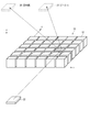
- FIG. 2 is a diagram schematically showing an example of a configuration of the mirror device shown in FIG. 1.
- the mirror device 10 includes a planar base material 11 and a plurality of optical elements 12 provided on the base material 11.
- the plurality of optical elements 12 are arranged, for example, in a matrix so as to spread in the x-direction and the y-direction orthogonal to each other.
- Each of the plurality of optical elements 12 has two reflecting surfaces arranged at right angles.
- the optical element 12 is composed of a cube or a rectangular parallelepiped.
- the base material 11 and the optical element 12 are made of a transparent resin.
- optical elements 12 are illustrated in FIG. 2, in reality, more optical elements 12 can be arranged.
- the number and size of the optical elements 12 can be arbitrarily set according to the specifications of the aerial display device 1. Further, the distance between the two optical elements 12 can be arbitrarily set according to the specifications of the aerial display device.
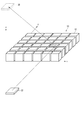
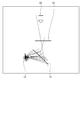
- FIG. 3 is a schematic diagram for explaining the principle of the aerial display device 1 of the embodiment.
- the aerial display device 1 includes a display unit 20 for displaying an image on a display surface and a mirror device 10.
- the base material 11 of the mirror device 10 is not shown, and only a plurality of optical elements 12 are extracted and shown.
- the plurality of optical elements 12 are arranged in the xy plane.
- the z direction is the height direction of the optical element 12.
- the light (display light) emitted from the display element 20 is reflected by the two sides of each of the plurality of optical elements 12.
- the optical path of the light reflected by the hatched optical element 12 is extracted and shown.
- the light emitted from the display element 20 is imaged at a position symmetrical to the display element 20 with respect to the mirror device 10, and an aerial image 30 is formed at the position. The observer can visually recognize this aerial image.
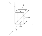
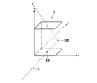
- FIG. 4 is a schematic diagram illustrating an example of the state of light reflected twice by one optical element of the mirror device shown in FIG. 2.
- FIG. 5 is a diagram showing an optical path when the optical element shown in FIG. 4 is viewed from the z direction.
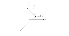
- FIG. 6 is a diagram showing an optical path when the optical element shown in FIG. 4 is viewed from the y direction.
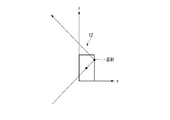
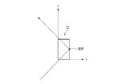
- FIG. 7 is a diagram showing an optical path when the optical element shown in FIG. 4 is viewed from the x direction.
- the light incident from the bottom surface of the optical element 12 is reflected by the first side surface, further reflected by the second side surface perpendicular to the first side surface, and emitted from the upper surface.
- the light incident on an arbitrary side surface of the optical element 12 is not reflected by all the light components on the side surface, but is divided into a reflection component and a transmission component.
- the reflection component is a component of light reflected at a reflection angle corresponding to the incident angle on the side surface
- the transmission component is a component of light transmitted linearly on the side surface as it is.
- one optical element 12 is composed of a cube or a rectangular parallelepiped having diagonal vertices in the x direction and the y direction, and the plurality of optical elements 12 are formed in the x direction and the y direction. It may be arranged.
- each of the plurality of optical elements 12 shown in FIGS. 2 to 7 may be arranged at a position rotated by 45 degrees with respect to the x direction.
- the reflecting surfaces 12A and 12B of each optical element 12 are arranged so as to have an angle of 45 degrees with respect to the x direction.
- the x-direction and the y-direction are directions substantially parallel to the end surface of the main surface of the base material 11 of the mirror device 10.
- a ghost generated by forming an image at an unintended position after the light emitted from the display element 20 is incident on the mirror device 10 will be described.
- a ghost is a double image that appears in the vicinity of the aerial image 30.
- FIG. 8 is a schematic diagram illustrating a ghost displayed by an aerial display device.
- the ghost 31 is an image formed by light reflected only once by the mirror device 10 (that is, light not reflected twice).
- the ghost 31 forms an image with respect to the mirror device 10 at a position that is not plane-symmetrical with the display element 20.
- FIG. 9 is a schematic diagram illustrating a state of light reflected once by one optical element of the mirror device shown in FIG.
- FIG. 10 is a diagram illustrating an optical path when the optical element shown in FIG. 9 is viewed from the z direction.
- FIG. 11 is a diagram illustrating an optical path when the optical element shown in FIG. 9 is viewed from the y direction.
- FIG. 12 is a diagram illustrating an optical path when the optical element shown in FIG. 9 is viewed from the x direction.
- the inventor of the present application performs a simulation for analyzing the cause of displaying the ghost 31, and proposes an aerial display device 1 in which the ghost 31 is not displayed.
- FIG. 13 is a diagram for explaining an example of simulation conditions for analyzing the cause of ghost display in the aerial display device.
- the light emitted from one or a plurality of point light sources L3 is used as the display light, and how the display light reflected by the mirror device 10 is observed at the image formation position D1 and the observation position D2 is analyzed.
- the image formation position D1 is a position where the display light reflected twice by the mirror device 10 is imaged.
- the observation position D2 is a position where the observer observes the aerial image imaged at the image formation position D1 reflected by the mirror device 10, and analyzes the simulation value obtained by retinal projection approximation imitating the human eye. ..
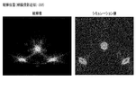
- FIG. 14 is a diagram showing an example of an observation image and a simulation value at the image formation position shown in FIG.
- FIG. 15 is a diagram showing an example of an observation image and a simulation value in the observation shown in FIG.
- the display light from the point light source L3 is imaged in both the observation image and the simulation value. Further, at the observation position D2, it can be seen that the display light formed by the point light source L3 is imaged and the ghost is generated in both the observation image and the simulation value. From these results, it can be seen that the results corresponding to the observed image are obtained by this simulation value.
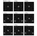
- FIG. 16 is a diagram showing an example of simulation values at the observation position when the light distribution of the light source is changed.
- the range of the light distribution of the light source L3 is ⁇ 10 degrees, ⁇ 20 degrees, ⁇ 30 degrees, ⁇ 40 degrees, ⁇ 50 degrees, ⁇ 60 degrees, ⁇ 70 degrees, ⁇ 80 degrees, and ⁇ 90 degrees, respectively.
- the simulation value at the observation position D2 is shown.
- the direction in which light is emitted from the light source L3 at 0 degrees is a direction forming an angle ⁇ (for example, 45 degrees) with respect to the main surface of the mirror device 10.
- the observation position D2 is further observed.
- a simulation of the display light visually visible was performed.
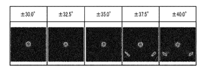
- FIG. 17 is a diagram showing another example of the simulation value at the observation position when the light distribution of the light source is changed.
- the range of the light distribution of the light source L3 is ⁇ 35.0 degrees
- ghost 31 starts to appear in the simulation result
- the range of the light distribution of the light source L3 is ⁇ 37.5 degrees and ⁇ .
- a result was obtained in which ghost 31 was generated in the simulation result.
- FIG. 18 is a diagram schematically showing a configuration example of a display unit of the aerial display device of the present embodiment.
- the display unit 20 of the aerial display device 1 of the present embodiment has a range of light distribution of emitted light ⁇ 35.0 degrees with respect to the normal direction (direction orthogonal to the display surface). It is configured to be within (greater than -35.0 degrees and less than +35.0 degrees).
- the display unit 20 includes a substrate 21, a light emitting element 22, a first lens 23, a second lens 24, a display element 25, and an optical control element 26.
- the substrate 21 is a plate-shaped member that supports the light emitting element 22 and the first lens 23.
- the light emitting element 22 is arranged on the substrate 21 and emits light so that the output ratio becomes maximum with respect to the normal direction of the main surface of the substrate 21.
- the light emitting element 22 includes, for example, one or more light emitting diodes.
- the light emitting diode emits white light, for example.
- the first lens 23 is arranged on the light emitting element 22.
- the first lens 23 is, for example, a plano-convex lens formed of optical glass, and is arranged at a predetermined distance from the light emitting element 22 so that the plane side of the first lens 23 faces the light emitting element 22.
- the first lens 23 may be arranged at least at a position where the light emitted from the light emitting element 22 is incident, and may be at least sized so as to be arranged on the light emitting element 22 and the region around the light emitting element 22. ..
- the second lens 24 is arranged on the first lens 23.
- the second lens 24 is, for example, a Fresnel lens of a plano-convex lens formed of a resin material, and has a predetermined distance from the first lens 23 so that the plane side of the second lens 24 faces the convex surface of the first lens 23. Placed and placed.
- the widths of the long side and the short side of the second lens 24 are about the same size as the display surface of the display unit 20, and are at least larger than the first lens 23.
- the display element 25 is, for example, a liquid crystal display element.
- a liquid crystal mode for example, a vertical orientation (VA) mode can be applied.
- the display element 25 is not limited to the liquid crystal display element in the VA mode, and may be a liquid crystal display element in the TN mode or the homogeneous mode.
- the optical control element 26 is arranged on the display element 25.
- the optical control element 26 includes, for example, a transparent region and a light-shielding region.
- the transparent area and the light-shielding area of the optical control element 26 extend substantially parallel to the longitudinal direction or the lateral direction of the optical control element 26 on a plane substantially parallel to the display surface of the display unit 20, and are alternately arranged in a stripe shape. Have been placed.
- the width of the transparent region of the optical control element 26 in the lateral direction is larger than the width of the light-shielding region in the lateral direction.
- FIG. 19 is a diagram schematically showing a configuration example of a display unit of the aerial display device of the embodiment.
- An example of the configuration of the first lens 23 and the second lens 24 is shown.
- the light source 22 includes one or a plurality of light emitting diodes, and emits light so that the output ratio is maximized in the normal direction of the display surface of the display unit 20.
- the first lens 23 is arranged on the light source 22 at an interval of 0.7 mm.
- the first lens 23 is, for example, a plano-convex lens formed of BK7, which is an optical glass, and is arranged so that the plane side faces the light source 22.
- the thickness of the first lens 23 (plane spacing: width in the optical axis direction of the lens center) is 1.2 mm, and the radius of curvature of the convex surface of the first lens 23 is 14.0 mm.
- the second lens 24 is arranged on the first lens 23 at an interval of 36.0 mm.
- the second lens 24 is, for example, a Fresnel lens of a plano-convex lens formed of an acrylic resin, and is arranged so that the plane side faces the convex surface of the first lens 23.
- the thickness of the second lens 24 (plane spacing: width in the optical axis direction of the lens center) is 2.0 mm, and the radius of curvature of the convex surface of the second lens 24 is 18.5 mm.
- the light source 22, the first lens 23, and the second lens 24 are not limited to the above materials and designs, and can be applied as long as they can realize the same operation.
- the range of the light distribution of the display light emitted from the display unit 20 is within the range of ⁇ 35.0 degrees (light distribution) with respect to the normal direction (0 degrees).
- the distribution can be greater than -35.0 degrees and less than +35.0 degrees).
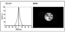
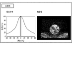
- 20 and 21 are diagrams for explaining an example of the effect of the aerial display device of the embodiment.
- an example of the light distribution of the display unit 20 and the observation image by the aerial display device 1 including the display unit 20 is shown.
- FIG. 20 shows an example of an observation image by an aerial display device using a display unit having a light distribution distribution range wider than ⁇ 80 degrees.
- the same image as in FIG. 20 is displayed on the display unit, but a ghost occurs in the observation image.
- the aerial display device 1 of the present embodiment in which the light distribution of the display unit 20 is larger than -35.0 degrees and less than +35.0 degrees, the generation of ghosts can be suppressed. rice field. That is, according to the aerial display device 1 of the present embodiment, it is possible to provide an aerial display device that ensures the display quality of an aerial image.
- the present invention is not limited to the above embodiment, and can be variously modified at the implementation stage without departing from the gist thereof.
- each embodiment may be carried out in combination as appropriate, in which case the combined effect can be obtained.
- the above-described embodiment includes various inventions, and various inventions can be extracted by a combination selected from a plurality of disclosed constituent requirements. For example, even if some constituent elements are deleted from all the constituent elements shown in the embodiment, if the problem can be solved and the effect is obtained, the configuration in which the constituent elements are deleted can be extracted as an invention.
- Aerial display device 10 ... Mirror device, 11 ... Base material, 12 ... Optical element, 12A ... Reflective surface, 12B ... Reflective surface, 20 ... Display unit, 20 ... Display element, 21 ... Board, 22 ... Light source, 22 ... Light source, 23 ... 1st lens, 24 ... 2nd lens, 25 ... Display element, 26 ... Optical control element, 30 ... Real image (aerial image), 31 ... ghost, 90 ... Observer, D1 ... Imaging position, D2 ... Observation position, L3 ... Light source
Landscapes
- Physics & Mathematics (AREA)
- General Physics & Mathematics (AREA)
- Optics & Photonics (AREA)
- Testing, Inspecting, Measuring Of Stereoscopic Televisions And Televisions (AREA)
- Fittings On The Vehicle Exterior For Carrying Loads, And Devices For Holding Or Mounting Articles (AREA)
- Massaging Devices (AREA)
- Led Device Packages (AREA)
Priority Applications (3)
| Application Number | Priority Date | Filing Date | Title |
|---|---|---|---|
| EP21817116.3A EP4163704A4 (en) | 2020-06-03 | 2021-05-27 | Aerial display device |
| CN202180039665.1A CN115917403A (zh) | 2020-06-03 | 2021-05-27 | 空中显示装置 |
| US18/060,280 US20230092598A1 (en) | 2020-06-03 | 2022-11-30 | Aerial display apparatus |
Applications Claiming Priority (2)
| Application Number | Priority Date | Filing Date | Title |
|---|---|---|---|
| JP2020-096737 | 2020-06-03 | ||
| JP2020096737A JP7516877B2 (ja) | 2020-06-03 | 2020-06-03 | 空中表示装置 |
Related Child Applications (1)
| Application Number | Title | Priority Date | Filing Date |
|---|---|---|---|
| US18/060,280 Continuation US20230092598A1 (en) | 2020-06-03 | 2022-11-30 | Aerial display apparatus |
Publications (1)
| Publication Number | Publication Date |
|---|---|
| WO2021246282A1 true WO2021246282A1 (ja) | 2021-12-09 |
Family
ID=78831132
Family Applications (1)
| Application Number | Title | Priority Date | Filing Date |
|---|---|---|---|
| PCT/JP2021/020209 WO2021246282A1 (ja) | 2020-06-03 | 2021-05-27 | 空中表示装置 |
Country Status (6)
Cited By (1)
| Publication number | Priority date | Publication date | Assignee | Title |
|---|---|---|---|---|
| JP2025079773A (ja) * | 2023-11-10 | 2025-05-22 | 達運精密工業股▲ふん▼有限公司 | ホログラフィック投影装置 |
Families Citing this family (4)
| Publication number | Priority date | Publication date | Assignee | Title |
|---|---|---|---|---|
| JP2023103848A (ja) * | 2022-01-14 | 2023-07-27 | 学校法人五島育英会 | 表示装置 |
| JP2023156707A (ja) * | 2022-04-13 | 2023-10-25 | マクセル株式会社 | 空間浮遊映像表示システムおよび空間浮遊映像処理システム |
| TWI877795B (zh) * | 2023-09-18 | 2025-03-21 | 黃旭華 | 一種改進型的雙角反射鏡陣列及應用於光固化式積層製造設備及方法 |
| JP7672177B1 (ja) * | 2024-05-14 | 2025-05-07 | Miraibar株式会社 | 空中映像入力端末 |
Citations (6)
| Publication number | Priority date | Publication date | Assignee | Title |
|---|---|---|---|---|
| JP2007328309A (ja) * | 2006-06-06 | 2007-12-20 | Mikuni Denshi Kk | 面光源装置ならびにプリズムシートと液晶表示装置 |
| JP2017067933A (ja) | 2015-09-29 | 2017-04-06 | 株式会社パリティ・イノベーションズ | 2面コーナーリフレクタアレイ |
| JP2017167224A (ja) * | 2016-03-14 | 2017-09-21 | 大日本印刷株式会社 | 空間浮遊映像表示装置 |
| JP2019032404A (ja) * | 2017-08-07 | 2019-02-28 | コニカミノルタ株式会社 | 空中映像表示装置 |
| JP2019105744A (ja) * | 2017-12-13 | 2019-06-27 | 船井電機株式会社 | 空中像表示装置 |
| WO2019240137A1 (ja) * | 2018-06-12 | 2019-12-19 | 凸版印刷株式会社 | 空中表示装置 |
Family Cites Families (4)
| Publication number | Priority date | Publication date | Assignee | Title |
|---|---|---|---|---|
| JP4734652B2 (ja) * | 2006-12-21 | 2011-07-27 | 独立行政法人情報通信研究機構 | 光学システム |
| JP2013257529A (ja) | 2012-05-18 | 2013-12-26 | Sharp Corp | 光学システム |
| WO2017099116A1 (ja) * | 2015-12-07 | 2017-06-15 | 国立大学法人宇都宮大学 | 表示装置及び空中像の表示方法 |
| TWM585357U (zh) * | 2019-04-29 | 2019-10-21 | 大陸商北京眸合科技有限公司 | 實現空中懸浮顯示的光學系統 |
-
2020
- 2020-06-03 JP JP2020096737A patent/JP7516877B2/ja active Active
-
2021
- 2021-05-27 WO PCT/JP2021/020209 patent/WO2021246282A1/ja unknown
- 2021-05-27 EP EP21817116.3A patent/EP4163704A4/en active Pending
- 2021-05-27 CN CN202180039665.1A patent/CN115917403A/zh active Pending
- 2021-06-02 TW TW110119958A patent/TWI797633B/zh active
-
2022
- 2022-11-30 US US18/060,280 patent/US20230092598A1/en active Pending
Patent Citations (6)
| Publication number | Priority date | Publication date | Assignee | Title |
|---|---|---|---|---|
| JP2007328309A (ja) * | 2006-06-06 | 2007-12-20 | Mikuni Denshi Kk | 面光源装置ならびにプリズムシートと液晶表示装置 |
| JP2017067933A (ja) | 2015-09-29 | 2017-04-06 | 株式会社パリティ・イノベーションズ | 2面コーナーリフレクタアレイ |
| JP2017167224A (ja) * | 2016-03-14 | 2017-09-21 | 大日本印刷株式会社 | 空間浮遊映像表示装置 |
| JP2019032404A (ja) * | 2017-08-07 | 2019-02-28 | コニカミノルタ株式会社 | 空中映像表示装置 |
| JP2019105744A (ja) * | 2017-12-13 | 2019-06-27 | 船井電機株式会社 | 空中像表示装置 |
| WO2019240137A1 (ja) * | 2018-06-12 | 2019-12-19 | 凸版印刷株式会社 | 空中表示装置 |
Non-Patent Citations (1)
| Title |
|---|
| See also references of EP4163704A4 |
Cited By (1)
| Publication number | Priority date | Publication date | Assignee | Title |
|---|---|---|---|---|
| JP2025079773A (ja) * | 2023-11-10 | 2025-05-22 | 達運精密工業股▲ふん▼有限公司 | ホログラフィック投影装置 |
Also Published As
| Publication number | Publication date |
|---|---|
| JP7516877B2 (ja) | 2024-07-17 |
| US20230092598A1 (en) | 2023-03-23 |
| TWI797633B (zh) | 2023-04-01 |
| EP4163704A4 (en) | 2023-12-20 |
| EP4163704A1 (en) | 2023-04-12 |
| TW202204938A (zh) | 2022-02-01 |
| CN115917403A (zh) | 2023-04-04 |
| JP2021189362A (ja) | 2021-12-13 |
Similar Documents
| Publication | Publication Date | Title |
|---|---|---|
| WO2021246282A1 (ja) | 空中表示装置 | |
| US11543583B2 (en) | Optical systems including light-guide optical elements with two-dimensional expansion | |
| CN108181715B (zh) | 用于在空中成像的系统 | |
| EP4130820B1 (en) | Multiple depth plane three-dimensional display using a wave guide reflector array projector | |
| TW202034000A (zh) | 包括具有二維擴展的光導光學元件的光學系統 | |
| JP5385080B2 (ja) | 表示装置 | |
| US20220357498A1 (en) | Method for Producing Light-Guide Optical Elements | |
| WO2019208097A1 (ja) | 空中表示装置 | |
| JP2014202835A (ja) | 照明装置及び画像表示装置 | |
| WO2015111420A1 (ja) | 表示装置 | |
| JP2017072788A (ja) | 照明装置およびプロジェクター | |
| WO2017130481A1 (ja) | ヘッドアップディスプレイ装置及びその生産方法 | |
| US20130009945A1 (en) | Electronic Display Method and Apparatus | |
| US20240142796A1 (en) | Air floating video display apparatus | |
| US7623189B2 (en) | Stereoscopic image display device comprising transmissive liquid crystal display element | |
| JP2025113710A (ja) | 虚像表示装置及び光学ユニット | |
| JP2024132721A (ja) | 光源装置およびプロジェクター | |
| JP2024126608A (ja) | 立体像表示装置 | |
| JP2002049003A (ja) | 磁気光学効果プロジェクタ、磁気光学効果投射方法、及び、ミラー基板 |
Legal Events
| Date | Code | Title | Description |
|---|---|---|---|
| 121 | Ep: the epo has been informed by wipo that ep was designated in this application |
Ref document number: 21817116 Country of ref document: EP Kind code of ref document: A1 |
|
| NENP | Non-entry into the national phase |
Ref country code: DE |
|
| ENP | Entry into the national phase |
Ref document number: 2021817116 Country of ref document: EP Effective date: 20230103 |