WO2021246282A1 - 空中表示装置 - Google Patents
空中表示装置 Download PDFInfo
- Publication number
- WO2021246282A1 WO2021246282A1 PCT/JP2021/020209 JP2021020209W WO2021246282A1 WO 2021246282 A1 WO2021246282 A1 WO 2021246282A1 JP 2021020209 W JP2021020209 W JP 2021020209W WO 2021246282 A1 WO2021246282 A1 WO 2021246282A1
- Authority
- WO
- WIPO (PCT)
- Prior art keywords
- display
- light
- aerial
- lens
- degrees
- Prior art date
Links
- 230000003287 optical effect Effects 0.000 claims description 64
- 238000010586 diagram Methods 0.000 description 41
- 238000004088 simulation Methods 0.000 description 27
- 239000000463 material Substances 0.000 description 8
- 230000015572 biosynthetic process Effects 0.000 description 6
- 230000000694 effects Effects 0.000 description 5
- 239000004973 liquid crystal related substance Substances 0.000 description 5
- 239000000470 constituent Substances 0.000 description 4
- 239000000758 substrate Substances 0.000 description 4
- 238000000034 method Methods 0.000 description 3
- 230000005540 biological transmission Effects 0.000 description 2
- 238000003384 imaging method Methods 0.000 description 2
- 239000005304 optical glass Substances 0.000 description 2
- 239000011347 resin Substances 0.000 description 2
- 229920005989 resin Polymers 0.000 description 2
- 239000004925 Acrylic resin Substances 0.000 description 1
- 229920000178 Acrylic resin Polymers 0.000 description 1
- 240000007594 Oryza sativa Species 0.000 description 1
- 235000007164 Oryza sativa Nutrition 0.000 description 1
- 230000004075 alteration Effects 0.000 description 1
- 230000002301 combined effect Effects 0.000 description 1
- 239000011159 matrix material Substances 0.000 description 1
- 230000004270 retinal projection Effects 0.000 description 1
- 235000009566 rice Nutrition 0.000 description 1
Images


Classifications
-
- G—PHYSICS
- G02—OPTICS
- G02B—OPTICAL ELEMENTS, SYSTEMS OR APPARATUS
- G02B30/00—Optical systems or apparatus for producing three-dimensional [3D] effects, e.g. stereoscopic images
- G02B30/60—Optical systems or apparatus for producing three-dimensional [3D] effects, e.g. stereoscopic images involving reflecting prisms and mirrors only
-
- G—PHYSICS
- G02—OPTICS
- G02B—OPTICAL ELEMENTS, SYSTEMS OR APPARATUS
- G02B30/00—Optical systems or apparatus for producing three-dimensional [3D] effects, e.g. stereoscopic images
- G02B30/50—Optical systems or apparatus for producing three-dimensional [3D] effects, e.g. stereoscopic images the image being built up from image elements distributed over a 3D volume, e.g. voxels
- G02B30/56—Optical systems or apparatus for producing three-dimensional [3D] effects, e.g. stereoscopic images the image being built up from image elements distributed over a 3D volume, e.g. voxels by projecting aerial or floating images
-
- G—PHYSICS
- G02—OPTICS
- G02B—OPTICAL ELEMENTS, SYSTEMS OR APPARATUS
- G02B27/00—Optical systems or apparatus not provided for by any of the groups G02B1/00 - G02B26/00, G02B30/00
- G02B27/0018—Optical systems or apparatus not provided for by any of the groups G02B1/00 - G02B26/00, G02B30/00 with means for preventing ghost images
Definitions
- the present invention relates to an aerial display device.
- the aerial display device uses, for example, a two-sided corner reflector array in which two-sided corner reflectors are arranged in an array to reflect light emitted from the display surface of a display element to form a real image in the air. ..
- the display method using the two-sided corner reflector array has no aberration, and a real image (hereinafter referred to as an aerial image) is displayed at a plane-symmetrical position.
- the present invention provides an aerial display device that ensures the display quality of an aerial image.
- the aerial display device of the embodiment according to the present invention has a display surface for displaying an image, and is arranged obliquely with respect to the display surface of the display unit and the display unit that emits display light from the display surface.
- a mirror device that reflects the display light emitted from the display unit and forms an aerial image at a position symmetrical to the display unit is provided, and the light distribution of the display light is a method of the display surface. It is larger than -35.0 degrees and less than +35.0 with the linear direction as 0 degrees.
- an aerial display device that ensures the display quality of an aerial image.
- FIG. 1 is a diagram schematically showing a configuration example of an aerial display device.
- FIG. 2 is a diagram schematically showing an example of a configuration of the mirror device shown in FIG. 1.
- FIG. 3 is a schematic diagram for explaining the principle of the aerial display device 1 of the embodiment.
- FIG. 4 is a schematic diagram illustrating an example of the state of light reflected twice by one optical element of the mirror device shown in FIG. 2.
- FIG. 5 is a diagram showing an optical path when the optical element shown in FIG. 4 is viewed from the z direction.
- FIG. 6 is a diagram showing an optical path when the optical element shown in FIG. 4 is viewed from the y direction.
- FIG. 7 is a diagram showing an optical path when the optical element shown in FIG. 4 is viewed from the x direction.
- FIG. 1 is a diagram schematically showing a configuration example of an aerial display device.
- FIG. 2 is a diagram schematically showing an example of a configuration of the mirror device shown in FIG. 1.
- FIG. 3 is
- FIG. 8 is a schematic diagram illustrating a ghost displayed by an aerial display device.
- FIG. 9 is a schematic diagram illustrating a state of light reflected once by one optical element of the mirror device shown in FIG.
- FIG. 10 is a diagram illustrating an optical path when the optical element shown in FIG. 9 is viewed from the z direction.
- FIG. 11 is a diagram illustrating an optical path when the optical element shown in FIG. 9 is viewed from the y direction.
- FIG. 12 is a diagram illustrating an optical path when the optical element shown in FIG. 9 is viewed from the x direction.
- FIG. 13 is a diagram for explaining an example of simulation conditions for analyzing the cause of ghost display in the aerial display device.
- FIG. 9 is a schematic diagram illustrating a state of light reflected once by one optical element of the mirror device shown in FIG.
- FIG. 10 is a diagram illustrating an optical path when the optical element shown in FIG. 9 is viewed from the z direction.
- FIG. 11 is a diagram illustrating an
- FIG. 14 is a diagram showing an example of an observation image and a simulation value at the image formation position shown in FIG.
- FIG. 15 is a diagram showing an example of an observation image and a simulation value in the observation shown in FIG.
- FIG. 16 is a diagram showing an example of simulation values at the observation position when the light distribution of the light source is changed.
- FIG. 17 is a diagram showing another example of the simulation value at the observation position when the light distribution of the light source is changed.
- FIG. 18 is a diagram schematically showing a configuration example of a display unit of the aerial display device of the present embodiment.
- FIG. 19 is a diagram schematically showing a configuration example of a display unit of the aerial display device of the embodiment.
- FIG. 20 is a diagram for explaining an example of the effect of the aerial display device of the embodiment.
- FIG. 21 is a diagram for explaining an example of the effect of the aerial display device of the embodiment.
- FIG. 1 is a diagram schematically showing a configuration example of an aerial display device.
- the aerial display device 1 includes a display unit 20 and a mirror device 10.
- the aerial display device 1 may include a display drive unit (not shown), a voltage supply circuit (not shown), and a control circuit (not shown), and may be driven by these external configurations. It may be controlled.
- the main surface of the mirror device 10 is juxtaposed parallel to the xy plane (shown in FIG. 2).
- the display surface of the display unit 20 is arranged so as to form an angle ⁇ of, for example, 45 degrees with respect to the xy plane.
- the main surface of the mirror device 10 is arranged obliquely with respect to the display surface of the display unit 20, for example, at 45 degrees. That is, the angle ⁇ formed by the display surface of the display unit 20 and the main surface of the mirror device 10 is, for example, 45 degrees.
- the angle ⁇ is not limited to 45 degrees and can be set in the range of 30 degrees or more and 60 degrees or less.
- the light emitted from the display unit 20 is reflected by the mirror device 10.
- the light reflected by the mirror device 10 forms a real image (aerial image) 30 in the air between the mirror device 10 and the observer 90.
- the aerial image 30 is imaged at a position symmetrical to the plane of the display unit 20 with respect to the mirror device 10.
- the display unit 20 has a light source and a display element (not shown).
- the light emitted from the light source is controlled by the optical system so that the light distribution is within a predetermined range, and is emitted toward the display element.
- the display element transmits incident light and displays an image, a moving image, or the like showing desired information. That is, the display element uses the light emitted from the light source to emit light for displaying an image, a moving image, or the like as an aerial image (hereinafter referred to as display light).
- the display surface of the display unit 20 is a surface on the side where the display light is emitted, and is a surface on the side facing the mirror device 10 in the aerial display device 1 of the present embodiment. The configuration of the display unit 20 applied to the aerial display device 1 of the present embodiment will be described later.
- the display drive unit drives the display element of the display unit 20 to display an image, a moving image, or the like on the display element.
- the voltage supply circuit generates a voltage necessary for operating the light source unit and the display drive unit of the display unit 20, and supplies these voltages to the light source unit and the display drive unit.
- the control circuit controls the operation of the entire aerial display device 1. That is, the control circuit controls the light source unit, the display drive unit, and the voltage supply circuit of the display unit 20, and displays the aerial image 30 at the display position between the mirror device 10 and the observer 90.
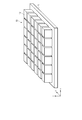
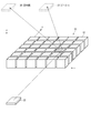
- FIG. 2 is a diagram schematically showing an example of a configuration of the mirror device shown in FIG. 1.
- the mirror device 10 includes a planar base material 11 and a plurality of optical elements 12 provided on the base material 11.
- the plurality of optical elements 12 are arranged, for example, in a matrix so as to spread in the x-direction and the y-direction orthogonal to each other.
- Each of the plurality of optical elements 12 has two reflecting surfaces arranged at right angles.
- the optical element 12 is composed of a cube or a rectangular parallelepiped.
- the base material 11 and the optical element 12 are made of a transparent resin.
- optical elements 12 are illustrated in FIG. 2, in reality, more optical elements 12 can be arranged.
- the number and size of the optical elements 12 can be arbitrarily set according to the specifications of the aerial display device 1. Further, the distance between the two optical elements 12 can be arbitrarily set according to the specifications of the aerial display device.
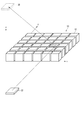
- FIG. 3 is a schematic diagram for explaining the principle of the aerial display device 1 of the embodiment.
- the aerial display device 1 includes a display unit 20 for displaying an image on a display surface and a mirror device 10.
- the base material 11 of the mirror device 10 is not shown, and only a plurality of optical elements 12 are extracted and shown.
- the plurality of optical elements 12 are arranged in the xy plane.
- the z direction is the height direction of the optical element 12.
- the light (display light) emitted from the display element 20 is reflected by the two sides of each of the plurality of optical elements 12.
- the optical path of the light reflected by the hatched optical element 12 is extracted and shown.
- the light emitted from the display element 20 is imaged at a position symmetrical to the display element 20 with respect to the mirror device 10, and an aerial image 30 is formed at the position. The observer can visually recognize this aerial image.
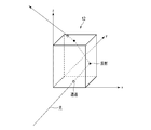
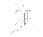
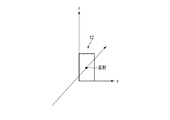
- FIG. 4 is a schematic diagram illustrating an example of the state of light reflected twice by one optical element of the mirror device shown in FIG. 2.
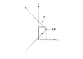
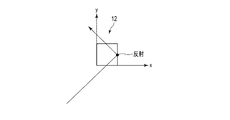
- FIG. 5 is a diagram showing an optical path when the optical element shown in FIG. 4 is viewed from the z direction.
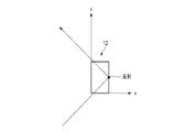
- FIG. 6 is a diagram showing an optical path when the optical element shown in FIG. 4 is viewed from the y direction.
- FIG. 7 is a diagram showing an optical path when the optical element shown in FIG. 4 is viewed from the x direction.
- the light incident from the bottom surface of the optical element 12 is reflected by the first side surface, further reflected by the second side surface perpendicular to the first side surface, and emitted from the upper surface.
- the light incident on an arbitrary side surface of the optical element 12 is not reflected by all the light components on the side surface, but is divided into a reflection component and a transmission component.
- the reflection component is a component of light reflected at a reflection angle corresponding to the incident angle on the side surface
- the transmission component is a component of light transmitted linearly on the side surface as it is.
- one optical element 12 is composed of a cube or a rectangular parallelepiped having diagonal vertices in the x direction and the y direction, and the plurality of optical elements 12 are formed in the x direction and the y direction. It may be arranged.
- each of the plurality of optical elements 12 shown in FIGS. 2 to 7 may be arranged at a position rotated by 45 degrees with respect to the x direction.
- the reflecting surfaces 12A and 12B of each optical element 12 are arranged so as to have an angle of 45 degrees with respect to the x direction.
- the x-direction and the y-direction are directions substantially parallel to the end surface of the main surface of the base material 11 of the mirror device 10.
- a ghost generated by forming an image at an unintended position after the light emitted from the display element 20 is incident on the mirror device 10 will be described.
- a ghost is a double image that appears in the vicinity of the aerial image 30.
- FIG. 8 is a schematic diagram illustrating a ghost displayed by an aerial display device.
- the ghost 31 is an image formed by light reflected only once by the mirror device 10 (that is, light not reflected twice).
- the ghost 31 forms an image with respect to the mirror device 10 at a position that is not plane-symmetrical with the display element 20.
- FIG. 9 is a schematic diagram illustrating a state of light reflected once by one optical element of the mirror device shown in FIG.
- FIG. 10 is a diagram illustrating an optical path when the optical element shown in FIG. 9 is viewed from the z direction.
- FIG. 11 is a diagram illustrating an optical path when the optical element shown in FIG. 9 is viewed from the y direction.
- FIG. 12 is a diagram illustrating an optical path when the optical element shown in FIG. 9 is viewed from the x direction.
- the inventor of the present application performs a simulation for analyzing the cause of displaying the ghost 31, and proposes an aerial display device 1 in which the ghost 31 is not displayed.
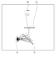
- FIG. 13 is a diagram for explaining an example of simulation conditions for analyzing the cause of ghost display in the aerial display device.
- the light emitted from one or a plurality of point light sources L3 is used as the display light, and how the display light reflected by the mirror device 10 is observed at the image formation position D1 and the observation position D2 is analyzed.
- the image formation position D1 is a position where the display light reflected twice by the mirror device 10 is imaged.
- the observation position D2 is a position where the observer observes the aerial image imaged at the image formation position D1 reflected by the mirror device 10, and analyzes the simulation value obtained by retinal projection approximation imitating the human eye. ..
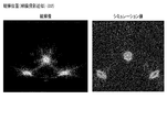
- FIG. 14 is a diagram showing an example of an observation image and a simulation value at the image formation position shown in FIG.
- FIG. 15 is a diagram showing an example of an observation image and a simulation value in the observation shown in FIG.
- the display light from the point light source L3 is imaged in both the observation image and the simulation value. Further, at the observation position D2, it can be seen that the display light formed by the point light source L3 is imaged and the ghost is generated in both the observation image and the simulation value. From these results, it can be seen that the results corresponding to the observed image are obtained by this simulation value.
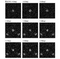
- FIG. 16 is a diagram showing an example of simulation values at the observation position when the light distribution of the light source is changed.
- the range of the light distribution of the light source L3 is ⁇ 10 degrees, ⁇ 20 degrees, ⁇ 30 degrees, ⁇ 40 degrees, ⁇ 50 degrees, ⁇ 60 degrees, ⁇ 70 degrees, ⁇ 80 degrees, and ⁇ 90 degrees, respectively.
- the simulation value at the observation position D2 is shown.
- the direction in which light is emitted from the light source L3 at 0 degrees is a direction forming an angle ⁇ (for example, 45 degrees) with respect to the main surface of the mirror device 10.
- the observation position D2 is further observed.
- a simulation of the display light visually visible was performed.
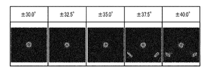
- FIG. 17 is a diagram showing another example of the simulation value at the observation position when the light distribution of the light source is changed.
- the range of the light distribution of the light source L3 is ⁇ 35.0 degrees
- ghost 31 starts to appear in the simulation result
- the range of the light distribution of the light source L3 is ⁇ 37.5 degrees and ⁇ .
- a result was obtained in which ghost 31 was generated in the simulation result.
- FIG. 18 is a diagram schematically showing a configuration example of a display unit of the aerial display device of the present embodiment.
- the display unit 20 of the aerial display device 1 of the present embodiment has a range of light distribution of emitted light ⁇ 35.0 degrees with respect to the normal direction (direction orthogonal to the display surface). It is configured to be within (greater than -35.0 degrees and less than +35.0 degrees).
- the display unit 20 includes a substrate 21, a light emitting element 22, a first lens 23, a second lens 24, a display element 25, and an optical control element 26.
- the substrate 21 is a plate-shaped member that supports the light emitting element 22 and the first lens 23.
- the light emitting element 22 is arranged on the substrate 21 and emits light so that the output ratio becomes maximum with respect to the normal direction of the main surface of the substrate 21.
- the light emitting element 22 includes, for example, one or more light emitting diodes.
- the light emitting diode emits white light, for example.
- the first lens 23 is arranged on the light emitting element 22.
- the first lens 23 is, for example, a plano-convex lens formed of optical glass, and is arranged at a predetermined distance from the light emitting element 22 so that the plane side of the first lens 23 faces the light emitting element 22.
- the first lens 23 may be arranged at least at a position where the light emitted from the light emitting element 22 is incident, and may be at least sized so as to be arranged on the light emitting element 22 and the region around the light emitting element 22. ..
- the second lens 24 is arranged on the first lens 23.
- the second lens 24 is, for example, a Fresnel lens of a plano-convex lens formed of a resin material, and has a predetermined distance from the first lens 23 so that the plane side of the second lens 24 faces the convex surface of the first lens 23. Placed and placed.
- the widths of the long side and the short side of the second lens 24 are about the same size as the display surface of the display unit 20, and are at least larger than the first lens 23.
- the display element 25 is, for example, a liquid crystal display element.
- a liquid crystal mode for example, a vertical orientation (VA) mode can be applied.
- the display element 25 is not limited to the liquid crystal display element in the VA mode, and may be a liquid crystal display element in the TN mode or the homogeneous mode.
- the optical control element 26 is arranged on the display element 25.
- the optical control element 26 includes, for example, a transparent region and a light-shielding region.
- the transparent area and the light-shielding area of the optical control element 26 extend substantially parallel to the longitudinal direction or the lateral direction of the optical control element 26 on a plane substantially parallel to the display surface of the display unit 20, and are alternately arranged in a stripe shape. Have been placed.
- the width of the transparent region of the optical control element 26 in the lateral direction is larger than the width of the light-shielding region in the lateral direction.
- FIG. 19 is a diagram schematically showing a configuration example of a display unit of the aerial display device of the embodiment.
- An example of the configuration of the first lens 23 and the second lens 24 is shown.
- the light source 22 includes one or a plurality of light emitting diodes, and emits light so that the output ratio is maximized in the normal direction of the display surface of the display unit 20.
- the first lens 23 is arranged on the light source 22 at an interval of 0.7 mm.
- the first lens 23 is, for example, a plano-convex lens formed of BK7, which is an optical glass, and is arranged so that the plane side faces the light source 22.
- the thickness of the first lens 23 (plane spacing: width in the optical axis direction of the lens center) is 1.2 mm, and the radius of curvature of the convex surface of the first lens 23 is 14.0 mm.
- the second lens 24 is arranged on the first lens 23 at an interval of 36.0 mm.
- the second lens 24 is, for example, a Fresnel lens of a plano-convex lens formed of an acrylic resin, and is arranged so that the plane side faces the convex surface of the first lens 23.
- the thickness of the second lens 24 (plane spacing: width in the optical axis direction of the lens center) is 2.0 mm, and the radius of curvature of the convex surface of the second lens 24 is 18.5 mm.
- the light source 22, the first lens 23, and the second lens 24 are not limited to the above materials and designs, and can be applied as long as they can realize the same operation.
- the range of the light distribution of the display light emitted from the display unit 20 is within the range of ⁇ 35.0 degrees (light distribution) with respect to the normal direction (0 degrees).
- the distribution can be greater than -35.0 degrees and less than +35.0 degrees).
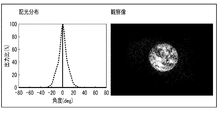
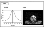
- 20 and 21 are diagrams for explaining an example of the effect of the aerial display device of the embodiment.
- an example of the light distribution of the display unit 20 and the observation image by the aerial display device 1 including the display unit 20 is shown.
- FIG. 20 shows an example of an observation image by an aerial display device using a display unit having a light distribution distribution range wider than ⁇ 80 degrees.
- the same image as in FIG. 20 is displayed on the display unit, but a ghost occurs in the observation image.
- the aerial display device 1 of the present embodiment in which the light distribution of the display unit 20 is larger than -35.0 degrees and less than +35.0 degrees, the generation of ghosts can be suppressed. rice field. That is, according to the aerial display device 1 of the present embodiment, it is possible to provide an aerial display device that ensures the display quality of an aerial image.
- the present invention is not limited to the above embodiment, and can be variously modified at the implementation stage without departing from the gist thereof.
- each embodiment may be carried out in combination as appropriate, in which case the combined effect can be obtained.
- the above-described embodiment includes various inventions, and various inventions can be extracted by a combination selected from a plurality of disclosed constituent requirements. For example, even if some constituent elements are deleted from all the constituent elements shown in the embodiment, if the problem can be solved and the effect is obtained, the configuration in which the constituent elements are deleted can be extracted as an invention.
- Aerial display device 10 ... Mirror device, 11 ... Base material, 12 ... Optical element, 12A ... Reflective surface, 12B ... Reflective surface, 20 ... Display unit, 20 ... Display element, 21 ... Board, 22 ... Light source, 22 ... Light source, 23 ... 1st lens, 24 ... 2nd lens, 25 ... Display element, 26 ... Optical control element, 30 ... Real image (aerial image), 31 ... ghost, 90 ... Observer, D1 ... Imaging position, D2 ... Observation position, L3 ... Light source
Landscapes
- Physics & Mathematics (AREA)
- General Physics & Mathematics (AREA)
- Optics & Photonics (AREA)
- Fittings On The Vehicle Exterior For Carrying Loads, And Devices For Holding Or Mounting Articles (AREA)
- Massaging Devices (AREA)
- Led Device Packages (AREA)
- Testing, Inspecting, Measuring Of Stereoscopic Televisions And Televisions (AREA)
Abstract
空中像の表示品質を確保する空中表示装置を提供する。実施形態による空中表示装置は、画像を表示する表示面を有し、表示面から表示光を出射する表示ユニット(20)と、表示ユニット(20)の表示面に対して斜めに配置され、表示ユニット(20)から出射された表示光を反射し、表示ユニット(20)と面対称な位置に空中像を結像するミラーデバイスと、を備え、表示光の配光分布は、表示面の法線方向を0度として-35.0度より大きく+35.0未満である。
Description
本発明は、空中表示装置に関する。
画像や動画などを空中映像として表示可能な空中表示装置が研究され、新しいヒューマン・マシン・インターフェースとして期待されている。空中表示装置は、例えば、2面コーナーリフレクタがアレイ状に配列された2面コーナーリフレクタアレイを用いて、表示素子の表示面から出射される光を反射し、空中に実像を結像している。2面コーナーリフレクタアレイによる表示法は、収差が無く、面対称位置に実像(以下、空中像)が表示される。
本発明は、空中像の表示品位を確保する空中表示装置を提供する。
本発明に係る実施形態の空中表示装置は、画像を表示する表示面を有し、前記表示面から表示光を出射する表示ユニットと、前記表示ユニットの前記表示面に対して斜めに配置され、前記表示ユニットから出射された前記表示光を反射し、前記表示ユニットと面対称な位置に空中像を結像するミラーデバイスと、を備え、前記表示光の配光分布は、前記表示面の法線方向を0度として-35.0度より大きく+35.0未満である。
本発明によれば、空中像の表示品質を確保する空中表示装置を提供することができる。
以下、実施形態について図面を参照して説明する。ただし、図面は模式的または概念的なものであり、各図面の寸法および比率等は必ずしも現実のものと同一とは限らない。また、図面の相互間で同じ部分を表す場合においても、互いの寸法の関係や比率が異なって表される場合もある。特に、以下に示す幾つかの実施形態は、本発明の技術思想を具体化するための装置および方法を例示したものであって、構成部品の形状、構造、配置等によって、本発明の技術思想が特定されるものではない。なお、以下の説明において、同一の機能及び構成を有する要素については同一符号を付し、重複説明は必要な場合にのみ行う。
[1] 第1実施形態
[1-1] 空中表示装置の原理
空中表示装置は、例えば液晶ディスプレイなどの表示ユニットの表示面から射出される光を、2面コーナーリフレクタ等の空中結像素子(ミラーデバイス)を用いて空間中に結像させるものである。
[1-1] 空中表示装置の原理
空中表示装置は、例えば液晶ディスプレイなどの表示ユニットの表示面から射出される光を、2面コーナーリフレクタ等の空中結像素子(ミラーデバイス)を用いて空間中に結像させるものである。
図1は、空中表示装置の一構成例を概略的に示す図である。
空中表示装置1は、表示ユニット20とミラーデバイス10とを含む。空中表示装置1は、表示駆動部(図示せず)、電圧供給回路(図示せず)、及び制御回路(図示せず)を備えていてもよく、外部に設けられたこれらの構成により駆動および制御されてもよい。
空中表示装置1は、表示ユニット20とミラーデバイス10とを含む。空中表示装置1は、表示駆動部(図示せず)、電圧供給回路(図示せず)、及び制御回路(図示せず)を備えていてもよく、外部に設けられたこれらの構成により駆動および制御されてもよい。
ミラーデバイス10の主面は、x-y平面(図2に示す)に対して平行に並置されている。表示ユニット20の表示面は、x-y平面に対して例えば45度の角度θを成すように配置されている。換言すると、ミラーデバイス10の主面は、表示ユニット20の表示面に対して斜めに、例えば45度で配置される。すなわち、表示ユニット20の表示面とミラーデバイス10の主面とがなす角度θは、例えば45度である。なお、角度θは、45度に限定されず、30度以上60度以下の範囲で設定可能である。
表示ユニット20から出射された光は、ミラーデバイス10により反射される。ミラーデバイス10により反射された光は、ミラーデバイス10と観察者90との間の空中に実像(空中像)30を結像する。空中像30は、ミラーデバイス10に対して表示ユニット20の面対称な位置に結像される。
表示ユニット20は、図示しない光源及び表示素子を有する。光源から出射された光は配光分布が所定の範囲となるように光学系により制御され、表示素子に向けて出射される。表示素子には、入射した光を透過すると共に、所望の情報を示す画像あるいは動画等を表示する。すなわち、表示素子は、光源から出射された光を用いて、画像あるいは動画等を空中像として表示するための光(以下、表示光)を出射する。表示ユニット20の表示面は表示光が出射する側の面であり、本実施形態の空中表示装置1ではミラーデバイス10に対向している側の面である。
本実施形態の空中表示装置1に適用される表示ユニット20の構成については後述する。
本実施形態の空中表示装置1に適用される表示ユニット20の構成については後述する。
表示駆動部は、表示ユニット20の表示素子を駆動し、表示素子に画像あるいは動画等を表示させる。
電圧供給回路は、表示ユニット20の光源部と表示駆動部とを動作させるのに必要な電圧を発生し、それらの電圧を光源部と表示駆動部とに供給する。
電圧供給回路は、表示ユニット20の光源部と表示駆動部とを動作させるのに必要な電圧を発生し、それらの電圧を光源部と表示駆動部とに供給する。
制御回路は、空中表示装置1全体の動作を制御する。すなわち、制御回路は、表示ユニット20の光源部、表示駆動部及び電圧供給回路を制御し、ミラーデバイス10と観察者90との間の表示位置に空中像30を表示させる。
図2は、図1に示すミラーデバイスの一構成例を概略的に示す図である。
ここでは、ミラーデバイス10の斜視図を示している。
ミラーデバイス10は、平面状の基材11と、基材11上に設けられた複数の光学要素12とを備える。複数の光学要素12は、互いに直交するx方向及びy方向に広がるように、例えばマトリクス状に配列される。複数の光学要素12の各々は、直角に配置された2つの反射面を有する。光学要素12は、立方体、又は直方体からなる。基材11及び光学要素12は、透明な樹脂で構成される。
ここでは、ミラーデバイス10の斜視図を示している。
ミラーデバイス10は、平面状の基材11と、基材11上に設けられた複数の光学要素12とを備える。複数の光学要素12は、互いに直交するx方向及びy方向に広がるように、例えばマトリクス状に配列される。複数の光学要素12の各々は、直角に配置された2つの反射面を有する。光学要素12は、立方体、又は直方体からなる。基材11及び光学要素12は、透明な樹脂で構成される。
なお、図2では、36(=6×6)個の光学要素12を例示しているが、実際には、これより多くの光学要素12が配列され得る。光学要素12の数及びサイズは、空中表示装置1の仕様に応じて、任意に設定可能である。また、2個の光学要素12の間隔は、空中表示装置の仕様に応じて、任意に設定可能である。
図3は、実施形態の空中表示装置1の原理を説明するための模式図である。
空中表示装置1は、表示面に画像を表示する表示ユニット20と、ミラーデバイス10とを備える。図3では、図面の理解が容易になるように、ミラーデバイス10のうち基材11の図示を省略し、複数の光学要素12のみを抽出して示している。複数の光学要素12は、x-y平面に配列される。z方向は、光学要素12の高さ方向である。
空中表示装置1は、表示面に画像を表示する表示ユニット20と、ミラーデバイス10とを備える。図3では、図面の理解が容易になるように、ミラーデバイス10のうち基材11の図示を省略し、複数の光学要素12のみを抽出して示している。複数の光学要素12は、x-y平面に配列される。z方向は、光学要素12の高さ方向である。
表示素子20から出射された光(表示光)は、複数の光学要素12の各々の2つの側面で反射される。図3では、ハッチングを付した光学要素12で反射される光の光路を抽出して示している。表示素子20から出射された光は、ミラーデバイス10に対して表示素子20と面対称の位置に結像し、当該位置に空中像30が結像される。観察者は、この空中像を視認することができる。
図4は、図2に示すミラーデバイスの1つの光学要素で2回反射される光の様子の一例を説明する模式図である。
図5は、図4に示した光学要素をz方向から見た場合の光路を示す図である。
図6は、図4に示した光学要素をy方向から見た場合の光路を示す図である。
図7は、図4に示した光学要素をx方向から見た場合の光路を示す図である。
図5は、図4に示した光学要素をz方向から見た場合の光路を示す図である。
図6は、図4に示した光学要素をy方向から見た場合の光路を示す図である。
図7は、図4に示した光学要素をx方向から見た場合の光路を示す図である。
光学要素12の底面から入射した光は、第1側面で反射され、第1側面と直角な第2側面でさらに反射され、上面から出射する。
なお、光学要素12の任意の側面に入射した光は、当該側面で全光成分が反射されるわけではなく、反射成分と透過成分とに分けられる。反射成分とは、当該側面で入射角に応じた反射角で反射する光の成分であり、透過成分とは、当該側面をそのまま直線的に透過する光の成分である。
なお、光学要素12の任意の側面に入射した光は、当該側面で全光成分が反射されるわけではなく、反射成分と透過成分とに分けられる。反射成分とは、当該側面で入射角に応じた反射角で反射する光の成分であり、透過成分とは、当該側面をそのまま直線的に透過する光の成分である。
なお、Z方向からミラーデバイス10を見たときに、1つの光学要素12はx方向及びy方向に対角の頂点を有する立方体又は直方体からなり、複数の光学要素12はx方向及びy方向に配列されてもよい。言い換えると、図2乃至図7に示した複数の光学要素12の各々がx方向に対して45度回転された位置に配置されていてもよい。この場合には、各光学要素12の反射面12A,12Bは、x方向に対して角度45度を有する状態で配置される。なお、x方向およびy方向は、ミラーデバイス10の基材11の主面の端辺と略平行な方向である。
(ゴーストについて)
次に、表示素子20から出射した光がミラーデバイス10に入射した後に意図しない位置で結像することにより生じるゴーストについて説明する。ゴーストとは、空中像30の近傍に現れる二重画像である。
次に、表示素子20から出射した光がミラーデバイス10に入射した後に意図しない位置で結像することにより生じるゴーストについて説明する。ゴーストとは、空中像30の近傍に現れる二重画像である。
図8は、空中表示装置によって表示されるゴーストを説明する模式図である。
ゴースト31は、ミラーデバイス10によって1回のみ反射された光(すなわち、2回反射されなかった光)により結像する画像である。ゴースト31は、ミラーデバイス10に対して表示素子20と面対称でない位置に結像する。
ゴースト31は、ミラーデバイス10によって1回のみ反射された光(すなわち、2回反射されなかった光)により結像する画像である。ゴースト31は、ミラーデバイス10に対して表示素子20と面対称でない位置に結像する。
図9は、図8に示すミラーデバイスの1つの光学要素で1回反射される光の様子を説明する模式図である。
図10は、図9に示す光学要素をz方向から見た場合の光路を説明する図である。
図11は、図9に示す光学要素をy方向から見た場合の光路を説明する図である。
図12は、図9に示す光学要素をx方向から見た場合の光路を説明する図である。
図10は、図9に示す光学要素をz方向から見た場合の光路を説明する図である。
図11は、図9に示す光学要素をy方向から見た場合の光路を説明する図である。
図12は、図9に示す光学要素をx方向から見た場合の光路を説明する図である。
光学要素12の底面から入射した光は、第1側面で反射され、第1側面と直角な第2側面を透過する。この経路で進む光は、ミラーデバイス10に対して表示素子20と面対称でない位置に結像し、ゴースト31を表示させる。
本願発明者は、上記ゴースト31が表示される原因を解析するためのシミュレーションを行い、ゴースト31が表示されない空中表示装置1を提案する。
本願発明者は、上記ゴースト31が表示される原因を解析するためのシミュレーションを行い、ゴースト31が表示されない空中表示装置1を提案する。
図13は、空中表示装置においてゴーストが表示される原因を解析したシミュレーション条件の一例を説明するための図である。
シミュレーションでは、1又は複数の点光源L3から出射される光を表示光とし、ミラーデバイス10で反射された表示光が、結像位置D1と、観察位置D2とでどのように観察されるか解析を行った。結像位置D1は、ミラーデバイス10において2回反射した表示光が結像される位置である。観察位置D2は、観察者がミラーデバイス10にて反射して結像位置D1に結像した空中像を観察する位置であって、人の目を模した網膜投影近似をしたシミュレーション値を解析する。
シミュレーションでは、1又は複数の点光源L3から出射される光を表示光とし、ミラーデバイス10で反射された表示光が、結像位置D1と、観察位置D2とでどのように観察されるか解析を行った。結像位置D1は、ミラーデバイス10において2回反射した表示光が結像される位置である。観察位置D2は、観察者がミラーデバイス10にて反射して結像位置D1に結像した空中像を観察する位置であって、人の目を模した網膜投影近似をしたシミュレーション値を解析する。
図14は、図13に示す結像位置における観察像とシミュレーション値との一例を示す図である。
図15は、図13に示す観察における観察像とシミュレーション値との一例を示す図である。
図15は、図13に示す観察における観察像とシミュレーション値との一例を示す図である。
結像位置D1では、観察像とシミュレーション値との両方に、点光源L3による表示光が結像している様子が見られている。また、観察位置D2では、観察像とシミュレーション値との両方に、点光源L3による表示光の結像している様子とともに、ゴーストが発生している様子が見られる。これらの結果から、このシミュレーション値により観察像に対応する結果が得られていることが分かる。
図16は、光源の配光分布を変更したときの観察位置におけるシミュレーション値の一例を示す図である。
ここでは、光源L3の配光分布の範囲が±10度、±20度、±30度、±40度、±50度、±60度、±70度、±80度、±90度のときそれぞれについて、観察位置D2におけるシミュレーション値を示している。なお、光源L3から光が出射する0度の方向(最も光の出力比が大きくなる方向)は、ミラーデバイス10の主面に対して角度θ(例えば45度)を成す方向である。
ここでは、光源L3の配光分布の範囲が±10度、±20度、±30度、±40度、±50度、±60度、±70度、±80度、±90度のときそれぞれについて、観察位置D2におけるシミュレーション値を示している。なお、光源L3から光が出射する0度の方向(最も光の出力比が大きくなる方向)は、ミラーデバイス10の主面に対して角度θ(例えば45度)を成す方向である。
シミュレーション結果を参照すると、光源L3の配光分布の範囲が広くなると、シミュレーション結果にゴースト31が生じる傾向があった。また、光源L3の配光分布が±30度のときには、シミュレーション結果にゴースト31が生じていないが、光源L3の配光分布の範囲が±40度のときには、シミュレーション結果にゴースト31が生じる結果が得られた。
そこで、光源L3の配光分布の範囲が±30.0度、±32.5度、±35.0度、±37.5度、±40.0度のときそれぞれについて、更に、観察位置D2に視認される表示光のシミュレーションを行った。
図17は、光源の配光分布を変更したときの観察位置におけるシミュレーション値の他の例を示す図である。
このシミュレーション結果を参照すると、光源L3の配光分布の範囲が±35.0度のときに、シミュレーション結果にゴースト31が生じ始め、光源L3の配光分布の範囲が±37.5度及び±40.0度のときには、シミュレーション結果にゴースト31が生じる結果が得られた。
このシミュレーション結果を参照すると、光源L3の配光分布の範囲が±35.0度のときに、シミュレーション結果にゴースト31が生じ始め、光源L3の配光分布の範囲が±37.5度及び±40.0度のときには、シミュレーション結果にゴースト31が生じる結果が得られた。
上記のシミュレーション結果より、光源L3の配光分布の範囲が法線方向(0度)に対して±35.0度の範囲を超えるときの光がゴースト像を発生させている事が分かった。したがって、表示ユニット20から出射される表示光の配光分布の範囲を法線方向に対して±35.0度に含める(-35.0度より大きく+35.0度未満とする)ことにより、ゴースト31の発生を抑制することができると考えられる。
図18は、本実施形態の空中表示装置の表示ユニットの一構成例を概略的に示す図である。
本実施形態の空中表示装置1の表示ユニット20は、上述のシミュレーション結果に基づき、出射する光の配光分布の範囲が法線方向(表示面に直交する方向)に対して±35.0度内(-35.0度より大きく+35.0度未満とする)となるように構成されている。
本実施形態の空中表示装置1の表示ユニット20は、上述のシミュレーション結果に基づき、出射する光の配光分布の範囲が法線方向(表示面に直交する方向)に対して±35.0度内(-35.0度より大きく+35.0度未満とする)となるように構成されている。
表示ユニット20は、基板21と、発光素子22と、第1レンズ23と、第2レンズ24と、表示素子25と、光制御素子26と、を備えている。
基板21は、発光素子22および第1レンズ23を支持する板状の部材である。
基板21は、発光素子22および第1レンズ23を支持する板状の部材である。
発光素子22は基板21上に配置され、基板21の主面の法線方向に対して出力比が最大となるように光を出射する。発光素子22は、例えば、1又は複数の発光ダイオードを備えている。発光ダイオードは、例えば白色の光を発光する。
第1レンズ23は、発光素子22上に配置されている。第1レンズ23は、例えば、光学ガラスにより形成された平凸レンズであって、第1レンズ23の平面側が発光素子22と対向するように発光素子22と所定の間隔を置いて配置されている。なお、第1レンズ23は、少なくとも発光素子22から出射される光の入射する位置に配置されていれば良く、発光素子22およびその周囲の領域の上に少なくとも配置される大きさであればよい。
第2レンズ24は、第1レンズ23上に配置されている。第2レンズ24は、例えば、樹脂材料により形成された平凸レンズのフレネルレンズであって、第2レンズ24の平面側が第1レンズ23の凸面と対向するように第1レンズ23と所定の間隔を置いて配置される。なお、第2レンズ24の長辺および短辺の幅は、表示ユニット20の表示面と同程度の大きさであり、少なくとも第1レンズ23よりも大型のレンズである。
表示素子25は、例えば液晶表示素子である。液晶モードとしては、例えば垂直配向(VA)モードを適用することができる。なお、表示素子25は、VAモードの液晶表示素子に限定されるものではなく、TNモードやホモジニアスモードの液晶表示素子であってもよい。
光制御素子26は、表示素子25の上に配置されている。光制御素子26は、例えば、透明領域と遮光領域とを備えている。光制御素子26の透明領域と遮光領域とは、表示ユニット20の表示面と略平行な平面において、光制御素子26の長手方向または短手方向と略平行に延び、交互にストライプ状に並んで配置されている。なお光制御素子26の透明領域の短手方向の幅は、遮光領域の短手方向の幅よりも大きい。
図19は、実施形態の空中表示装置の表示ユニットの一構成例を概略的に示す図である。
ここでは、表示ユニット20から出射される表示光の配光分布の範囲が表示面の法線方向に対して-35.0度より大きく+35.0度未満の範囲となるときの、光源22、第1レンズ23及び第2レンズ24の構成の一例を示している。
ここでは、表示ユニット20から出射される表示光の配光分布の範囲が表示面の法線方向に対して-35.0度より大きく+35.0度未満の範囲となるときの、光源22、第1レンズ23及び第2レンズ24の構成の一例を示している。
光源22は、1又は複数の発光ダイオードを含み、表示ユニット20の表示面の法線方向に出力比が最大となるように光を出射する。
第1レンズ23は、光源22上に0.7mmの間隔を置いて配置されている。第1レンズ23は例えば光学ガラスであるBK7により形成された平凸レンズであって、平面側が光源22に対向するように配置されている。第1レンズ23の厚さ(面間隔:レンズ中心の光軸方向における幅)は1.2mmであって、第1レンズ23の凸面の曲率半径は14.0mmである。
第1レンズ23は、光源22上に0.7mmの間隔を置いて配置されている。第1レンズ23は例えば光学ガラスであるBK7により形成された平凸レンズであって、平面側が光源22に対向するように配置されている。第1レンズ23の厚さ(面間隔:レンズ中心の光軸方向における幅)は1.2mmであって、第1レンズ23の凸面の曲率半径は14.0mmである。
第2レンズ24は、第1レンズ23上に36.0mmの間隔を置いて第2レンズ24が配置されている。第2レンズ24は例えばアクリル樹脂により形成された平凸レンズのフレネルレンズであって、平面側が第1レンズ23の凸面と対向するように配置されている。第2レンズ24の厚さ(面間隔:レンズ中心の光軸方向における幅)は2.0mmであって、第2レンズ24の凸面の曲率半径は18.5mmである。
なお、光源22、第1レンズ23及び第2レンズ24は上記の材料や設計に限定されるものではなく、同様の作用を実現できるものであれば適用することが可能である。
なお、光源22、第1レンズ23及び第2レンズ24は上記の材料や設計に限定されるものではなく、同様の作用を実現できるものであれば適用することが可能である。
上記のように表示ユニット20を構成することにより、表示ユニット20から出射される表示光の配光分布の範囲を法線方向(0度)に対して±35.0度の範囲内(配光分布を-35.0度より大きく+35.0度未満とする)とすることができる。
次に、本実施形態の空中表示装置の効果について説明する。
図20及び図21は、実施形態の空中表示装置の効果の一例を説明するための図である。
ここでは、表示ユニット20の配光分布と、表示ユニット20を含む空中表示装置1による観察像との一例を示している。
図20及び図21は、実施形態の空中表示装置の効果の一例を説明するための図である。
ここでは、表示ユニット20の配光分布と、表示ユニット20を含む空中表示装置1による観察像との一例を示している。
図20によれば、空中表示装置1の表示ユニット20の配光分布を-35.0度より大きく+35.0度未満の範囲とするとしたとき、観察像にはゴーストが生じなかった。 一方で、図21では、配光分布の範囲が±80度よりも広い表示ユニットを用いた空中表示装置による観察像の一例を示している。この例では図20の場合と同じ画像を表示ユニットに表示させているが、観察像にゴーストが発生した。
上記のように、表示ユニット20の配光分布を-35.0度より大きく+35.0度未満の範囲とした本実施形態の空中表示装置1によれば、ゴーストの発生を抑制することができた。すなわち、本実施形態の空中表示装置1によれば、空中像の表示品質を確保する空中表示装置を提供することができる。
なお、本発明は、上記実施形態に限定されるものではなく、実施段階ではその要旨を逸脱しない範囲で種々に変形することが可能である。また、各実施形態は適宜組み合わせて実施してもよく、その場合組み合わせた効果が得られる。更に、上記実施形態には種々の発明が含まれており、開示される複数の構成要件から選択された組み合わせにより種々の発明が抽出され得る。例えば、実施形態に示される全構成要件からいくつかの構成要件が削除されても、課題が解決でき、効果が得られる場合には、この構成要件が削除された構成が発明として抽出され得る。
1…空中表示装置、10…ミラーデバイス、11…基材、12…光学要素、12A…反射面、12B…反射面、20…表示ユニット、20…表示素子、21…基板、22…光源、22…発光素子、23…第1レンズ、24…第2レンズ、25…表示素子、26…光制御素子、30…実像(空中像)、31…ゴースト、90…観察者、D1…結像位置、D2…観察位置、L3…光源
Claims (5)
- 画像を表示する表示面を有し、前記表示面から表示光を出射する表示ユニットと、
前記表示ユニットの前記表示面に対して斜めに配置され、前記表示ユニットから出射された前記表示光を反射し、前記表示ユニットと面対称な位置に空中像を結像するミラーデバイスと、を備え、
前記表示光の配光分布は、前記表示面の法線方向を0度として-35.0度より大きく+35.0未満である、空中表示装置。 - 前記表示ユニットは、
光源と、
前記光源上に所定の間隔をおいて配置される第1レンズと、
前記第2レンズ上に所定の間隔をおいて配置される第2レンズと、
前記第2レンズ上に配置された表示素子と、
前記表示素子上に配置され、互いに交互に並んで配置された複数の透明領域と複数の遮光領域とを備えた光制御素子と、を備え、
前記第1レンズは、平面側が前記光源に対向するように配置された平凸レンズであって。
前記第2レンズは、平面側が前記第1レンズに対向するように配置されたフレネルレンズである、請求項1記載の空中表示装置。 - 前記ミラーデバイスは、直角に配置された2つの反射面をそれぞれが含む複数の光学要素を有する請求項1又は請求項2に記載の空中表示装置。
- 前記複数の光学要素の各々は、立方体または直方体からなる請求項3に記載の空中表示装置。
- 前記ミラーデバイスの主面と、前記表示ユニットの前記表示面とがなす角度は、45度である請求項1乃至請求項4のいずれか1項に記載の空中表示装置。
Priority Applications (3)
| Application Number | Priority Date | Filing Date | Title |
|---|---|---|---|
| EP21817116.3A EP4163704A4 (en) | 2020-06-03 | 2021-05-27 | AIR DISPLAY DEVICE |
| CN202180039665.1A CN115917403A (zh) | 2020-06-03 | 2021-05-27 | 空中显示装置 |
| US18/060,280 US20230092598A1 (en) | 2020-06-03 | 2022-11-30 | Aerial display apparatus |
Applications Claiming Priority (2)
| Application Number | Priority Date | Filing Date | Title |
|---|---|---|---|
| JP2020096737A JP2021189362A (ja) | 2020-06-03 | 2020-06-03 | 空中表示装置 |
| JP2020-096737 | 2020-06-03 |
Related Child Applications (1)
| Application Number | Title | Priority Date | Filing Date |
|---|---|---|---|
| US18/060,280 Continuation US20230092598A1 (en) | 2020-06-03 | 2022-11-30 | Aerial display apparatus |
Publications (1)
| Publication Number | Publication Date |
|---|---|
| WO2021246282A1 true WO2021246282A1 (ja) | 2021-12-09 |
Family
ID=78831132
Family Applications (1)
| Application Number | Title | Priority Date | Filing Date |
|---|---|---|---|
| PCT/JP2021/020209 WO2021246282A1 (ja) | 2020-06-03 | 2021-05-27 | 空中表示装置 |
Country Status (6)
| Country | Link |
|---|---|
| US (1) | US20230092598A1 (ja) |
| EP (1) | EP4163704A4 (ja) |
| JP (1) | JP2021189362A (ja) |
| CN (1) | CN115917403A (ja) |
| TW (1) | TWI797633B (ja) |
| WO (1) | WO2021246282A1 (ja) |
Families Citing this family (1)
| Publication number | Priority date | Publication date | Assignee | Title |
|---|---|---|---|---|
| JP2023156707A (ja) * | 2022-04-13 | 2023-10-25 | マクセル株式会社 | 空間浮遊映像表示システムおよび空間浮遊映像処理システム |
Citations (6)
| Publication number | Priority date | Publication date | Assignee | Title |
|---|---|---|---|---|
| JP2007328309A (ja) * | 2006-06-06 | 2007-12-20 | Mikuni Denshi Kk | 面光源装置ならびにプリズムシートと液晶表示装置 |
| JP2017067933A (ja) | 2015-09-29 | 2017-04-06 | 株式会社パリティ・イノベーションズ | 2面コーナーリフレクタアレイ |
| JP2017167224A (ja) * | 2016-03-14 | 2017-09-21 | 大日本印刷株式会社 | 空間浮遊映像表示装置 |
| JP2019032404A (ja) * | 2017-08-07 | 2019-02-28 | コニカミノルタ株式会社 | 空中映像表示装置 |
| JP2019105744A (ja) * | 2017-12-13 | 2019-06-27 | 船井電機株式会社 | 空中像表示装置 |
| WO2019240137A1 (ja) * | 2018-06-12 | 2019-12-19 | 凸版印刷株式会社 | 空中表示装置 |
Family Cites Families (4)
| Publication number | Priority date | Publication date | Assignee | Title |
|---|---|---|---|---|
| JP4734652B2 (ja) * | 2006-12-21 | 2011-07-27 | 独立行政法人情報通信研究機構 | 光学システム |
| JP2013257529A (ja) * | 2012-05-18 | 2013-12-26 | Sharp Corp | 光学システム |
| WO2017099116A1 (ja) * | 2015-12-07 | 2017-06-15 | 国立大学法人宇都宮大学 | 表示装置及び空中像の表示方法 |
| TWM585357U (zh) * | 2019-04-29 | 2019-10-21 | 大陸商北京眸合科技有限公司 | 實現空中懸浮顯示的光學系統 |
-
2020
- 2020-06-03 JP JP2020096737A patent/JP2021189362A/ja active Pending
-
2021
- 2021-05-27 WO PCT/JP2021/020209 patent/WO2021246282A1/ja unknown
- 2021-05-27 CN CN202180039665.1A patent/CN115917403A/zh active Pending
- 2021-05-27 EP EP21817116.3A patent/EP4163704A4/en active Pending
- 2021-06-02 TW TW110119958A patent/TWI797633B/zh active
-
2022
- 2022-11-30 US US18/060,280 patent/US20230092598A1/en active Pending
Patent Citations (6)
| Publication number | Priority date | Publication date | Assignee | Title |
|---|---|---|---|---|
| JP2007328309A (ja) * | 2006-06-06 | 2007-12-20 | Mikuni Denshi Kk | 面光源装置ならびにプリズムシートと液晶表示装置 |
| JP2017067933A (ja) | 2015-09-29 | 2017-04-06 | 株式会社パリティ・イノベーションズ | 2面コーナーリフレクタアレイ |
| JP2017167224A (ja) * | 2016-03-14 | 2017-09-21 | 大日本印刷株式会社 | 空間浮遊映像表示装置 |
| JP2019032404A (ja) * | 2017-08-07 | 2019-02-28 | コニカミノルタ株式会社 | 空中映像表示装置 |
| JP2019105744A (ja) * | 2017-12-13 | 2019-06-27 | 船井電機株式会社 | 空中像表示装置 |
| WO2019240137A1 (ja) * | 2018-06-12 | 2019-12-19 | 凸版印刷株式会社 | 空中表示装置 |
Non-Patent Citations (1)
| Title |
|---|
| See also references of EP4163704A4 |
Also Published As
| Publication number | Publication date |
|---|---|
| TW202204938A (zh) | 2022-02-01 |
| TWI797633B (zh) | 2023-04-01 |
| EP4163704A1 (en) | 2023-04-12 |
| JP2021189362A (ja) | 2021-12-13 |
| CN115917403A (zh) | 2023-04-04 |
| US20230092598A1 (en) | 2023-03-23 |
| EP4163704A4 (en) | 2023-12-20 |
Similar Documents
| Publication | Publication Date | Title |
|---|---|---|
| US11543583B2 (en) | Optical systems including light-guide optical elements with two-dimensional expansion | |
| CA2876335C (en) | Multiple depth plane three-dimensional display using a wave guide reflector array projector | |
| JP5385080B2 (ja) | 表示装置 | |
| US10698149B2 (en) | Display for two-dimensional and/or three-dimensional images | |
| US20220357498A1 (en) | Method for Producing Light-Guide Optical Elements | |
| US9958679B2 (en) | Electro-optical device having optical element including a plurality of light guiding materials bonded via a half mirror layer | |
| JP2017215571A (ja) | ヘッドアップディスプレイ装置及び画像投射ユニット | |
| JP2014202835A (ja) | 照明装置及び画像表示装置 | |
| WO2018168089A1 (ja) | 表示装置 | |
| JP2018511148A (ja) | 出力の指向性制御を有する表示装置、およびこのような表示装置用のバックライトおよび光指向方法 | |
| JP2017015955A (ja) | 表示装置 | |
| WO2015111420A1 (ja) | 表示装置 | |
| WO2021246282A1 (ja) | 空中表示装置 | |
| WO2017130481A1 (ja) | ヘッドアップディスプレイ装置及びその生産方法 | |
| US11947139B2 (en) | Aerial display apparatus | |
| JP2017072788A (ja) | 照明装置およびプロジェクター | |
| US20130009945A1 (en) | Electronic Display Method and Apparatus | |
| KR20190085829A (ko) | 이미지 표시 장치 | |
| US7623189B2 (en) | Stereoscopic image display device comprising transmissive liquid crystal display element | |
| WO2022045010A1 (ja) | 空中表示装置 | |
| JP2002049003A (ja) | 磁気光学効果プロジェクタ、磁気光学効果投射方法、及び、ミラー基板 | |
| HU227172B1 (hu) | Eljárás és berendezés háromdimenziós képek megjelenítésére |
Legal Events
| Date | Code | Title | Description |
|---|---|---|---|
| 121 | Ep: the epo has been informed by wipo that ep was designated in this application |
Ref document number: 21817116 Country of ref document: EP Kind code of ref document: A1 |
|
| NENP | Non-entry into the national phase |
Ref country code: DE |
|
| ENP | Entry into the national phase |
Ref document number: 2021817116 Country of ref document: EP Effective date: 20230103 |