WO2021246032A1 - カテーテル - Google Patents
カテーテル Download PDFInfo
- Publication number
- WO2021246032A1 WO2021246032A1 PCT/JP2021/012979 JP2021012979W WO2021246032A1 WO 2021246032 A1 WO2021246032 A1 WO 2021246032A1 JP 2021012979 W JP2021012979 W JP 2021012979W WO 2021246032 A1 WO2021246032 A1 WO 2021246032A1
- Authority
- WO
- WIPO (PCT)
- Prior art keywords
- shaft
- hub
- accommodating portion
- base end
- catheter
- Prior art date
Links
- 230000004927 fusion Effects 0.000 claims abstract description 46
- 230000007423 decrease Effects 0.000 claims abstract description 18
- 230000002093 peripheral effect Effects 0.000 claims abstract description 13
- 239000000463 material Substances 0.000 description 14
- 238000000926 separation method Methods 0.000 description 13
- 238000000034 method Methods 0.000 description 10
- 230000003014 reinforcing effect Effects 0.000 description 9
- 229920005989 resin Polymers 0.000 description 8
- 239000011347 resin Substances 0.000 description 8
- 239000000049 pigment Substances 0.000 description 7
- 239000000470 constituent Substances 0.000 description 6
- 238000002834 transmittance Methods 0.000 description 5
- 230000001678 irradiating effect Effects 0.000 description 4
- 239000000853 adhesive Substances 0.000 description 3
- 230000001070 adhesive effect Effects 0.000 description 3
- 239000002872 contrast media Substances 0.000 description 3
- 238000010438 heat treatment Methods 0.000 description 3
- 239000000203 mixture Substances 0.000 description 3
- 230000001012 protector Effects 0.000 description 3
- 238000005452 bending Methods 0.000 description 2
- 230000005540 biological transmission Effects 0.000 description 2
- 229920001971 elastomer Polymers 0.000 description 2
- 239000000806 elastomer Substances 0.000 description 2
- 238000002347 injection Methods 0.000 description 2
- 239000007924 injection Substances 0.000 description 2
- 239000000155 melt Substances 0.000 description 2
- 229910052751 metal Inorganic materials 0.000 description 2
- 239000002184 metal Substances 0.000 description 2
- 238000000465 moulding Methods 0.000 description 2
- 229920006122 polyamide resin Polymers 0.000 description 2
- 229920001225 polyester resin Polymers 0.000 description 2
- 239000004645 polyester resin Substances 0.000 description 2
- 229920005672 polyolefin resin Polymers 0.000 description 2
- YCKRFDGAMUMZLT-UHFFFAOYSA-N Fluorine atom Chemical compound [F] YCKRFDGAMUMZLT-UHFFFAOYSA-N 0.000 description 1
- 238000005033 Fourier transform infrared spectroscopy Methods 0.000 description 1
- 229910052779 Neodymium Inorganic materials 0.000 description 1
- 239000004952 Polyamide Substances 0.000 description 1
- 238000010521 absorption reaction Methods 0.000 description 1
- 238000004026 adhesive bonding Methods 0.000 description 1
- 229910052797 bismuth Inorganic materials 0.000 description 1
- JCXGWMGPZLAOME-UHFFFAOYSA-N bismuth atom Chemical compound [Bi] JCXGWMGPZLAOME-UHFFFAOYSA-N 0.000 description 1
- 210000004204 blood vessel Anatomy 0.000 description 1
- 238000009954 braiding Methods 0.000 description 1
- 239000006229 carbon black Substances 0.000 description 1
- 150000001875 compounds Chemical class 0.000 description 1
- 230000006835 compression Effects 0.000 description 1
- 238000007906 compression Methods 0.000 description 1
- 239000004020 conductor Substances 0.000 description 1
- 238000002059 diagnostic imaging Methods 0.000 description 1
- 230000005674 electromagnetic induction Effects 0.000 description 1
- 239000000835 fiber Substances 0.000 description 1
- 239000012530 fluid Substances 0.000 description 1
- 229910052731 fluorine Inorganic materials 0.000 description 1
- 239000011737 fluorine Substances 0.000 description 1
- PCHJSUWPFVWCPO-UHFFFAOYSA-N gold Chemical compound [Au] PCHJSUWPFVWCPO-UHFFFAOYSA-N 0.000 description 1
- 229910052737 gold Inorganic materials 0.000 description 1
- 239000010931 gold Substances 0.000 description 1
- 230000006698 induction Effects 0.000 description 1
- 238000001746 injection moulding Methods 0.000 description 1
- 230000009545 invasion Effects 0.000 description 1
- 230000003902 lesion Effects 0.000 description 1
- 238000012986 modification Methods 0.000 description 1
- 230000004048 modification Effects 0.000 description 1
- QEFYFXOXNSNQGX-UHFFFAOYSA-N neodymium atom Chemical compound [Nd] QEFYFXOXNSNQGX-UHFFFAOYSA-N 0.000 description 1
- 229910001000 nickel titanium Inorganic materials 0.000 description 1
- 239000008188 pellet Substances 0.000 description 1
- 229920002647 polyamide Polymers 0.000 description 1
- 229920005668 polycarbonate resin Polymers 0.000 description 1
- 239000004431 polycarbonate resin Substances 0.000 description 1
- 229920000728 polyester Polymers 0.000 description 1
- -1 polytetrafluoroethylene Polymers 0.000 description 1
- 229920001343 polytetrafluoroethylene Polymers 0.000 description 1
- 239000004810 polytetrafluoroethylene Substances 0.000 description 1
- 229920003225 polyurethane elastomer Polymers 0.000 description 1
- 229920005749 polyurethane resin Polymers 0.000 description 1
- 238000003825 pressing Methods 0.000 description 1
- 230000002787 reinforcement Effects 0.000 description 1
- 239000004065 semiconductor Substances 0.000 description 1
- 229910001220 stainless steel Inorganic materials 0.000 description 1
- 239000010935 stainless steel Substances 0.000 description 1
- 229920005992 thermoplastic resin Polymers 0.000 description 1
- WFKWXMTUELFFGS-UHFFFAOYSA-N tungsten Chemical compound [W] WFKWXMTUELFFGS-UHFFFAOYSA-N 0.000 description 1
- 229910052721 tungsten Inorganic materials 0.000 description 1
- 239000010937 tungsten Substances 0.000 description 1
- 238000004804 winding Methods 0.000 description 1
Images


Classifications
-
- A—HUMAN NECESSITIES
- A61—MEDICAL OR VETERINARY SCIENCE; HYGIENE
- A61M—DEVICES FOR INTRODUCING MEDIA INTO, OR ONTO, THE BODY; DEVICES FOR TRANSDUCING BODY MEDIA OR FOR TAKING MEDIA FROM THE BODY; DEVICES FOR PRODUCING OR ENDING SLEEP OR STUPOR
- A61M25/00—Catheters; Hollow probes
- A61M25/0009—Making of catheters or other medical or surgical tubes
- A61M25/0014—Connecting a tube to a hub
-
- A—HUMAN NECESSITIES
- A61—MEDICAL OR VETERINARY SCIENCE; HYGIENE
- A61M—DEVICES FOR INTRODUCING MEDIA INTO, OR ONTO, THE BODY; DEVICES FOR TRANSDUCING BODY MEDIA OR FOR TAKING MEDIA FROM THE BODY; DEVICES FOR PRODUCING OR ENDING SLEEP OR STUPOR
- A61M25/00—Catheters; Hollow probes
- A61M25/0067—Catheters; Hollow probes characterised by the distal end, e.g. tips
-
- A—HUMAN NECESSITIES
- A61—MEDICAL OR VETERINARY SCIENCE; HYGIENE
- A61M—DEVICES FOR INTRODUCING MEDIA INTO, OR ONTO, THE BODY; DEVICES FOR TRANSDUCING BODY MEDIA OR FOR TAKING MEDIA FROM THE BODY; DEVICES FOR PRODUCING OR ENDING SLEEP OR STUPOR
- A61M25/00—Catheters; Hollow probes
- A61M25/0097—Catheters; Hollow probes characterised by the hub
-
- A—HUMAN NECESSITIES
- A61—MEDICAL OR VETERINARY SCIENCE; HYGIENE
- A61M—DEVICES FOR INTRODUCING MEDIA INTO, OR ONTO, THE BODY; DEVICES FOR TRANSDUCING BODY MEDIA OR FOR TAKING MEDIA FROM THE BODY; DEVICES FOR PRODUCING OR ENDING SLEEP OR STUPOR
- A61M25/00—Catheters; Hollow probes
- A61M25/0043—Catheters; Hollow probes characterised by structural features
- A61M2025/0058—Catheters; Hollow probes characterised by structural features having an electroactive polymer material, e.g. for steering purposes, for control of flexibility, for locking, for opening or closing
-
- A—HUMAN NECESSITIES
- A61—MEDICAL OR VETERINARY SCIENCE; HYGIENE
- A61M—DEVICES FOR INTRODUCING MEDIA INTO, OR ONTO, THE BODY; DEVICES FOR TRANSDUCING BODY MEDIA OR FOR TAKING MEDIA FROM THE BODY; DEVICES FOR PRODUCING OR ENDING SLEEP OR STUPOR
- A61M25/00—Catheters; Hollow probes
- A61M2025/0098—Catheters; Hollow probes having a strain relief at the proximal end, e.g. sleeve
Definitions
- the present invention relates to a catheter.
- the shaft is placed in an injection mold, a part of the shaft is held down by a fixing pin, and the resin for the hub is injection molded at high temperature and high pressure. Therefore, there is a possibility that the fixing pin may deform the shaft or shift the shaft in the axial direction. Deformation of the shaft and misalignment in the axial direction may cause a decrease in the fixing strength between the shaft and the hub.
- the catheter according to the present invention that achieves the above object is a tube body having a lumen that communicates from the tip end to the base end, and has a shaft base end surface through which the lumen opens and a shaft outer surface that is an outer peripheral surface of the tube body.
- a catheter comprising a shaft provided and a hub attached to the base end of the shaft, wherein the hub has a tubular accommodating portion for accommodating the shaft, the accommodating portion being outside the shaft. It has a hub fusion surface that is directly fused to the surface, and is characterized in that the absolute value of the residual strain of the accommodating portion decreases radially outward from the hub fusion surface.
- the contour line of the absolute value of the residual strain of the accommodating portion in the cross section passing through the axial center of the accommodating portion may be formed in an arc shape which is convex outward in the radial direction.
- the absolute value of the residual strain gradually decreases from the site of the hub fusion surface having the largest value in both the radial outward direction and the axial center direction (tip direction and proximal direction). Therefore, it is possible to effectively suppress the occurrence of distortion in the shape of the accommodating portion.
- the shaft base end surface may be fused to the hub. This makes it possible to fix the shaft and hub more firmly.
- the catheter 10 suppresses bending of the shaft 20 which is a long tube, the hub 40 fixed to the base end of the shaft 20, and the shaft 20. It is equipped with a flexible kink-resistant protector 60 for the purpose of.
- the catheter 10 may be a guiding catheter, a contrast catheter, a microcatheter, or a balloon catheter or a diagnostic imaging catheter having a lumen for expansion, in addition to a catheter that supports a guide wire.
- the catheter 10 may be an over-the-wire (OTW) type in which a guide wire lumen communicating from the tip of the shaft to the hub is formed, or a rapid exchange (RX) type in which a guide wire lumen is formed only in the tip of the shaft.
- OW over-the-wire
- RX rapid exchange
- the guide wire lumen of an RX-type balloon catheter is formed from the tip of the shaft to an opening in the middle of the shaft in the axial direction.
- the expansion lumen for circulating the fluid that expands the balloon of the RX-type balloon catheter is formed so as to communicate from the balloon to the hub at the base end of the catheter.
- the shaft 20 is formed with a lumen 21 that communicates from the tip end to the base end.
- the shaft 20 has an outer surface 22 of the shaft, an inner surface 23 of the shaft, and a base end surface 24 of the shaft.
- the shaft outer surface 22 is a radial outer surface of the shaft 20 which is a tubular body, and extends from the tip end to the base end of the shaft 20.
- the shaft outer surface 22 has a shaft base end side outer surface 25 formed from the base end of the shaft 20 toward the tip end to a predetermined position.
- the outer surface 25 on the base end side of the shaft is surrounded by and accommodated in the hub 40.
- the outer surface 25 on the base end side of the shaft has a substantially uniform outer diameter along the axis X of the shaft 20.
- the outer surface 25 on the base end side of the shaft has a shaft fusion surface 26 fused to the hub 40 and a shaft separation surface 27 arranged on the distal end side of the shaft fusion surface 26 and away from the hub 40. There is.
- the shaft separating surface 27 is separated from the hub 40 with a gap without being fused to the hub 40.
- the shaft base end surface 24 is a surface facing the base end side at the base end of the shaft 20, and is formed by being cut perpendicular to the axis X of the shaft 20.
- the shaft 20 in the present embodiment has an inner layer 28 forming the inner surface 23 of the shaft, an outer layer 29 forming the outer surface 22 of the shaft, and a reinforcing body 30 embedded in the shaft 20.
- Examples of the constituent material of the outer layer 29 include polyamide resin, polyester resin, polyolefin resin, polyurethane resin, polyamide elastomer, polyester elastomer, polyurethane elastomer, or a mixture of one or more of these or a mixture having different hardness.
- the outer layer 29 may be made by arranging materials having different hardness so as to be flexible from the base end to the tip end.
- the constituent material of the inner layer 28 may be the same material as the constituent material of the outer layer 29 described above, or may be a material different from the constituent material of the outer layer 29.
- the constituent material of the inner layer 28 may be a fluorine-based resin material such as polytetrafluoroethylene resin in order to improve the slidability of the inner peripheral surface of the shaft 20.
- the hub 40 has a tubular accommodating portion 41 arranged on the distal end side to accommodate the proximal end portion of the shaft 20, a hub main body 42 arranged on the proximal end side of the accommodating portion 41, a wing 52, and a thread cutting protrusion 53. And an annular protrusion 54.
- the hub 40 has a hub lumen 45 that communicates from the hub tip opening 43 formed at the tip of the accommodating portion 41 to the hub base end opening 44 formed at the base end of the hub body 42.
- the hub lumen 45 has an accommodating surface 46 which is an inner peripheral surface of the accommodating portion 41, an adjacent surface 47 facing the shaft base end surface 24, and a hub passage 48 which is an inner peripheral surface of the hub main body 42.
- the accommodating surface 46 has a hub fusion surface 49 that is directly fused to the shaft fusion surface 26 of the outer surface 25 on the base end side of the shaft, and a hub separation surface 50 that is radially outwardly opposed to the shaft separation surface 27. And have.
- the hub fusion surface 49 extends from the base end of the accommodating surface 46 toward the tip end.
- the base end of the hub fusion surface 49 is connected to the adjacent surface 47.
- the hub separating surface 50 extends from the tip of the hub fusion surface 49 toward the tip.
- the gap between the hub separating surface 50 in the radial direction and the outer surface 25 on the base end side of the shaft widens toward the tip end.
- the hub separation surface 50 that forms a gap with the outer surface 25 on the base end side of the shaft may not be provided.
- the hub passage 48 extends from the adjacent surface 47 toward the base end.
- the hub passage 48 is formed in a tapered shape with an inner diameter that gradually increases toward the proximal end.
- the hub passage 48 is preferably coaxial with the accommodating surface 46 and further coaxial with the lumen 21.
- the inner diameter of the tip of the hub passage 48 is preferably, but not limited to, substantially the same as the inner diameter of the shaft 20.
- a portion of the tapered hub passage 48 may have a luer taper portion 51 that can be connected to a syringe (not shown).
- the guide wire or treatment catheter inserted through the hub proximal opening 44 smoothly passes through the hub lumen 45 and lumen 21 and projects from the tip of the catheter 10. As a result, the guide wire and the treatment catheter 10 can easily reach the target position such as the lesion.
- the wing 52 is formed so as to project from two facing positions on the outer peripheral surface of the hub body 42 so that the operator can easily grip and operate the hub 40.
- the thread cutting protrusion 53 is formed on the outer peripheral surface of the hub main body 42 on the base end side.
- the thread cutting protrusion 53 can be engaged with a lock type syringe or the like.
- the annular protrusion 54 is a protrusion formed on the outer peripheral surface of the accommodating portion 41 over 360 °.
- the annular protrusion 54 can be fitted into a groove formed on the inner peripheral surface of the kink-resistant protector 60.
- the constituent material of the hub 40 is not particularly limited as long as it is a thermoplastic resin capable of injection molding, but a material that easily transmits heat or electromagnetic waves is preferable, and specifically, a polyolefin resin, a polyamide resin, a polycarbonate resin, and a polyester resin. And so on.
- the inner diameter of the accommodating surface 46 of the hub 40 before the shaft 20 is fused is larger on the distal end side than on the proximal end side.
- the inner diameter D1 of the hub tip opening 43 is larger than the inner diameter D2 of the tip and the base end of the hub fusion surface 49.
- the inner diameter D3 at the tip of the hub passage 48 is smaller than the inner diameter D2 at the base end of the hub fusion surface 49.
- the inner diameter D2 of the hub fusion surface 49 substantially coincides with the outer diameter of the outer surface 25 on the base end side of the shaft.
- the inner diameter D1 of the hub tip opening 43 is, for example, 0.92 mm.
- the inner diameter D2 of the base end of the hub fusion surface 49 is, for example, 0.88 mm.
- the inner diameter D3 at the tip of the hub passage 48 is, for example, 0.57 mm.
- the base end side of the shaft 20 is inserted into the accommodating portion 41, and the shaft base end surface 24 is brought into contact with the adjacent surface 47.
- the shaft base end surface 24 may have a gap between the shaft base end surface 24 and the adjacent surface 47 without abutting on the adjacent surface 47.
- the proximal end of the outer surface 25 on the proximal end side of the shaft abuts on the proximal end of the hub fusion surface 49.
- the outer surface 25 on the base end side of the shaft may not abut on the fusion surface 49 on the base end side of the shaft, and there may be a gap between the outer surface 25 on the base end side of the shaft and the fusion surface 49 on the hub base end side.
- a mandrel (not shown) is inserted into the lumen 21 of the shaft 20 to heat the outer surface 25 on the base end side of the shaft and the accommodating portion 41 of the hub 40.
- the outer surface 25 on the base end side of the shaft and the accommodating surface 46 are melted, and the hub fusion surface 49 and the shaft fusion surface 26 are fused.
- the hub fusion surface 49 and the shaft fusion surface 26 may be mixed to form an integral structure.
- the heating method is not particularly limited, and examples thereof include a method of irradiating an electromagnetic wave having a wavelength that passes through the hub 40 and does not pass through the outer surface 22 of the shaft.
- Electromagnetic waves include heat, microwaves, visible light, and infrared rays.
- Infrared rays are near-infrared rays having a wavelength of about 0.7 ⁇ m to 2.5 ⁇ m, mid-infrared rays having a wavelength of about 2.5 ⁇ m to 4 ⁇ m, or far-infrared rays having a wavelength of about 4 ⁇ m to 1000 ⁇ m, but are near-infrared rays, mid-infrared rays, or far-infrared rays. It may be used alone or in combination of two or more, and may contain visible light or microwaves.
- the method of irradiating the electromagnetic wave is not particularly limited, but a semiconductor solid-state laser such as a YAG laser using neodymium or a fiber laser may be used.
- the transmission of electromagnetic waves means that in addition to being transparent to the naked eye by visible light, the measured transmittance (hereinafter referred to as transmittance) is 80% or more, more preferably 85% or more.
- the transmittance is determined by irradiating a sheet with a thickness of 0.4 mm to 0.5 mm prepared by melt-pressing resin pellets with an electromagnetic wave of a specific wavelength, and using a spectroscopic analyzer, for example, a Fourier transform infrared / near-infrared spectroscopic analyzer. Can be measured using. Therefore, since the electromagnetic wave is not limited to visible light, the transmission of the electromagnetic wave includes that it is transparent to a specific wavelength even if it looks colored or opaque to the naked eye.
- electromagnetic waves are not transmitted means that the transmittance is less than 80%, preferably less than 10%, and more preferably less than 1%, in addition to being visible to the naked eye as opaque or colored by visible light. .. Therefore, since electromagnetic waves are not limited to visible light, the fact that electromagnetic waves are opaque includes opacity or absorption of specific wavelengths even if they appear transparent to the naked eye.
- the outer layer 29 contains a pigment that does not transmit or absorbs heat or electromagnetic waves in an amount of 0.01 wt% or more and less than 10 wt%, preferably 0.05 wt% or more and 5 wt% or less, and more preferably 0.1 wt% or more and 1% or less of the total resin. , May be mixed.
- the outer layer 29 may not contain a pigment, a contrast medium, or the like, and the resin forming the outer layer 29 may have a low transmittance for a specific wavelength.
- the outer layer 29 may be replaced with a pigment or mixed with a metal having X-ray contrast property.
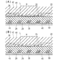
- the electromagnetic wave transmitted through the hub 40 transparent to the wavelength of the irradiated infrared laser L is generated. It is absorbed by the opaque resin or pigment of the outer layer 29 of the shaft 20 and mainly generates heat. As a result, the resin of the outer layer 29 is melted and heat H is transferred to the accommodating portion 41 of the hub 40, and at least a part of the accommodating surface 46 is melted. As shown in FIG. 5B, the melted accommodating surface 46 has a reduced diameter and is in close contact with the outer surface 25 on the base end side of the shaft, and is fused to the outer surface 25 on the base end side of the shaft.
- the hub fusion surface 49 and the shaft fusion surface 26 are fused and formed.
- the accommodating surface 46 melts and shrinks in diameter, but the outer peripheral surface of the accommodating portion 41 hardly melts because heat is hardly transferred and hardly deforms. Therefore, due to the reduced diameter of the accommodating surface 46, the material constituting the accommodating surface 46 flows so as to fill the gap between the accommodating surface 46 and the outer surface 25 on the base end side of the shaft, and as a result, the axial center X of the accommodating portion 41 is reached. The length along is reduced. As a result, the accommodating portion 41 and the outer surface 25 on the base end side of the shaft are satisfactorily fused without any gap. Further, the shaft base end surface 24 and the adjacent surface 47 are also melted and fused by the heat generated by the outer layer 29. The shaft base end surface 24 does not have to be fused to the adjacent surface 47.
- the contour lines C drawn by connecting the points of the same residual strain of the hub 40 are formed in an arc shape which is convex outward in the radial direction as shown in FIG. That is, the absolute value of the residual strain is large in the substantially center in the direction along the axis X in the fused range of the accommodating portion 41, decreases outward in the radial direction, and is the tip along the axis X. Decreases in the direction and the proximal direction.
- the contour lines C are formed in a shape similar to a part of an elliptical arc having a long axis extending along the axis X.
- the contour surface of the hub 40 connecting the points of the same residual strain has a shape similar to a part of the outer peripheral surface of a spheroid having a long axis extending along the axis X. It is formed.
- the catheter 10 is a tube body in which a lumen 21 communicating from the tip end to the base end is formed, and the shaft base end surface 24 through which the lumen 21 opens and the shaft which is the outer peripheral surface of the tube body.
- a catheter 10 having a shaft 20 with an outer surface 22 and a hub 40 attached to the proximal end of the shaft 20, the hub 40 having a tubular accommodating portion 41 accommodating the shaft 20.
- the accommodating portion 41 has a hub fusion surface 49 that is directly fused to the shaft outer surface 22, and the absolute value of the residual strain of the accommodating portion 41 decreases radially outward from the hub fusion surface 49. do.
- the absolute value of the residual strain of the accommodating portion 41 decreases radially outward from the hub fusion surface 49 due to fusion, so that the shaft 20 and the hub 40 are firmly fixed.
- it can be firmly fused, and it is possible to suppress a decrease in dimensional accuracy on the outer side of the hub 40 in the radial direction. Therefore, when the high pressure of the contrast medium injected into the catheter 10 acts, or when a tensile force acts between the hub 40 and the shaft 20 when the shaft 20 is pulled out from the body, the shaft from the hub 40 It is possible to prevent 20 from coming off.
- the shaft base end surface 24 is fused to the hub 40. As a result, the shaft 20 and the hub 40 can be fixed more firmly.
- a hub separation surface 50 is formed on the tip end side of the accommodating portion 41 so as to be separated from the outer surface 22 of the shaft outward in the radial direction and face each other.
- the shaft 20 tends to bend inside the tip of the accommodating portion 41, so that stress concentration of the shaft 20 can be suppressed and damage to the shaft 20 can be suppressed.
- the shaft 20 is easily bent inside the tip of the accommodating portion 41, it is possible to suppress the action of a force that tends to peel off from the shaft 20 on the hub fusion surface 49 of the accommodating portion 41 when the shaft 20 is bent.
- the fixing of the shaft 20 and the hub 40 can be effectively maintained.
- the heating of the shaft 20 may be performed by high frequency induction heating which heats by using electromagnetic induction.
- the electromagnetically induced conductor is, for example, a reinforcing body 30.
Abstract
【課題】シャフトとハブを強固に固定しつつ、ハブの径方向の外側の寸法精度が低下することを抑制できるカテーテルを提供する。 【解決手段】先端から基端まで連通するルーメン(21)が形成された管体であり、ルーメン(21)が開口するシャフト基端面(24)および管体の外周面であるシャフト外表面(22)を備えたシャフト(20)と、シャフト(20)の基端に取り付けられたハブ(40)と、を有するカテーテル(10)であって、ハブ(40)は、シャフト(20)を収容する筒状の収容部(41)を有し、収容部(41)は、シャフト外表面(22)と直接的に融着したハブ融着面(49)を有し、収容部(41)の残留ひずみの絶対値は、ハブ融着面(49)から径方向の外側へ向かって減少する。
Description
本発明は、カテーテルに関する。
近年、外科的侵襲が非常に低いという理由から、カテーテルを用いた血管等の管腔内の治療が盛んに行われている。カテーテルは、通常、先端から基端まで連通するルーメンを有するシャフトと、シャフトの基端に配置されるハブとを有している。ハブは、シリンジなどと接続するために、ルーメンに連通する通路が形成される。
ハブにシャフトの基端を固定する方法として、インサート成形方法、接着剤による接着方法などが知られている。
特許文献1に記載のインサート成形方法は、シャフトを射出用金型内に配置して固定ピンでシャフトの一部を抑えて、ハブ用の樹脂を高温高圧で射出成型する。このため、固定ピンによるシャフトの変形やシャフトの軸心方向へのずれが生じる可能性がある。シャフトの変形や軸心方向のずれは、シャフトとハブの固定強度の低下を生じさせる可能性がある。
また、特許文献2に記載の接着剤による接着方法では、シャフト外径とハブのシャフト収容部の内腔の隙間が小さすぎると、接着剤が流入できずに、ハブとシャフトの間に隙間が残り、シャフトとハブの固定強度の低下を生じさせる可能性がある。シャフト外径とハブのシャフト収容部の内腔の隙間が大きすぎると、ハブとシャフトの間の隙間を接着剤により完全に満たすことが困難となり、シャフトとハブの固定強度の低下を生じさせる可能性がある。
本発明は、上述した課題を解決するためになされたものであり、シャフトとハブを強固に固定しつつ、ハブの径方向の外側の寸法精度が低下することを抑制できるカテーテルを提供することを目的とする。
上記目的を達成する本発明に係るカテーテルは、先端から基端まで連通するルーメンが形成された管体であり、前記ルーメンが開口するシャフト基端面および前記管体の外周面であるシャフト外表面を備えたシャフトと、前記シャフトの基端に取り付けられたハブと、を有するカテーテルであって、前記ハブは、前記シャフトを収容する筒状の収容部を有し、前記収容部は、前記シャフト外表面と直接的に融着したハブ融着面を有し、前記収容部の残留ひずみの絶対値は、前記ハブ融着面から径方向の外側へ向かって減少することを特徴とする。
上記のように構成したカテーテルは、融着によって収容部の残留ひずみの絶対値が、ハブ融着面から径方向の外側へ向かって減少するため、シャフトとハブを強固に固定しつつ、強固に融着することができ、ハブの径方向の外側の寸法精度が低下することを抑制できる。
前記収容部の軸心を通る断面における前記収容部の残留ひずみの絶対値の等高線は、径方向の外側へ向かって凸状となる円弧状に形成されてもよい。これにより、残留ひずみの絶対値は、最も大きいハブ融着面の部位から、径方向の外側へ向かう方向および軸心方向の両方向(先端方向および基端方向)へ向かって徐々に減少する。このため、収容部の形状の歪みの発生を効果的に抑制できる。
前記シャフト基端面は、前記ハブに融着されてもよい。これにより、シャフトとハブをさらに強固に固定できる。
前記収容部の先端側に、前記シャフト外表面から径方向の外側へ離れて対向するハブ離間面が形成されてもよい。これにより、収容部の先端の内側でシャフトが曲がりやすくなるため、シャフトの応力集中を抑制し、シャフトの損傷を抑制できる。また、収容部の先端の内側でシャフトが曲がりやすくなることで、シャフトが曲がる際に、収容部のハブ融着面にシャフトから剥がれようとする力が作用することを抑制し、シャフトとハブの固定を効果的に維持できる。
以下、図面を参照して、本発明の実施の形態を説明する。なお、図面の寸法比率は、説明の都合上、誇張されて実際の比率とは異なる場合がある。以下の説明において、カテーテルの操作する側を「基端側」、生体内へ挿入される側を「先端側」と称することとする。
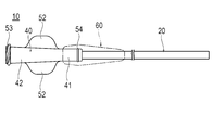
本発明の実施形態に係るカテーテル10は、図1~3に示すように、長尺な管体であるシャフト20と、シャフト20の基端に固着されたハブ40と、シャフト20の折れ曲がりを抑制するための柔軟な耐キンクプロテクタ60とを備えている。カテーテル10は、ガイドワイヤをサポートするカテーテルの他、ガイディングカテーテル、造影カテーテル、マイクロカテーテルでもよく、あるいは拡張用のルーメンを有するバルーンカテーテルや画像診断カテーテルでもよい。また、カテーテル10は、シャフトの先端からハブまで連通するガイドワイヤルーメンが形成されたオーバーザワイヤー(OTW)型でもよく、シャフトの先端部にのみガイドワイヤルーメンが形成されたラピッドエクスチェンジ(RX)型でもよい。例えば、RX型のバルーンカテーテルのガイドワイヤルーメンは、シャフトの先端からシャフトの軸心方向の途中の開口部まで形成される。RX型のバルーンカテーテルのバルーンを拡張させる流体を流通させる拡張用ルーメンは、バルーンからカテーテルの基端のハブまで連通して形成される。
シャフト20は、先端から基端まで連通するルーメン21が形成されている。シャフト20は、シャフト外表面22と、シャフト内表面23と、シャフト基端面24とを有している。
シャフト外表面22は、管体であるシャフト20の径方向の外側の面であり、シャフト20の先端から基端まで延在する。シャフト外表面22は、シャフト20の基端から先端に向かって所定の位置まで形成されるシャフト基端側外表面25を有している。シャフト基端側外表面25は、ハブ40に囲まれて収容されている。シャフト基端側外表面25は、シャフト20の軸心Xに沿って略均一の外径を有している。シャフト基端側外表面25は、ハブ40に融着されたシャフト融着面26と、シャフト融着面26の先端側に配置されてハブ40から離れているシャフト離間面27とを有している。シャフト離間面27は、ハブ40に融着されずに、ハブ40から隙間を有して離れている。
シャフト内表面23は、管体であるシャフト20の径方向の内側の面であり、シャフト20の先端から基端まで延在する。
シャフト基端面24は、シャフト20の基端で基端側を向く面であり、シャフト20の軸心Xに対して垂直に切断されて形成される。
本実施形態におけるシャフト20は、シャフト内表面23を形成する内層28と、シャフト外表面22を形成する外層29と、シャフト20に埋設される補強体30とを有している。
外層29の構成材料は、例えば、ポリアミド樹脂、ポリエステル樹脂、ポリオレフィン樹脂、ポリウレタン樹脂のほか、ポリアミドエラストマー、ポリエステルエラストマー、ポリウレタンエラストマー、あるいはこれらの1種以上の混合物あるいは硬度が異なるものの混合物が挙げられる。外層29は、基端から先端に向かって柔軟となるように硬度の異なる材料を配列したものでもよい。
内層28の構成材料は、上述した外層29の構成材料と同じ材料であってもよく、あるいは外層29の構成材料と異なる材料であってもよい。内層28の構成材料は、シャフト20内周面の摺動性を高めるために、ポリテトラフルオロエチレン樹脂等のフッ素系樹脂材料であってもよい。
補強体30は、シャフト20を補強するものであり、複数の補強線31を筒状に編組して形成される。また、補強体30は、1本以上の補強線31をらせん状に巻回して形成されてもよい。補強体30における複数の補強線31の隙間には、外層29あるいは内層28の材料が入り込んでいる。補強線31は、ステンレス鋼、NiTi等の金属で構成される。
ハブ40は、先端側に配置されてシャフト20の基端部を収容する筒状の収容部41と、収容部41の基端側に配置されるハブ本体42と、ウイング52と、ねじ切り突起53と、環状突起54とを有している。ハブ40は、収容部41の先端に形成されるハブ先端開口43から、ハブ本体42の基端に形成されるハブ基端開口44まで連通するハブ内腔45が形成される。ハブ内腔45は、収容部41の内周面である収容面46と、シャフト基端面24と対向する隣接面47と、ハブ本体42の内周面であるハブ通路48とを有する。
収容面46は、シャフト基端側外表面25のシャフト融着面26と直接的に融着したハブ融着面49と、シャフト離間面27から径方向の外側へ離れて対向するハブ離間面50とを有する。ハブ融着面49は、収容面46の基端から先端方向へ延在している。ハブ融着面49の基端は、隣接面47に接続されている。ハブ離間面50は、ハブ融着面49の先端から先端方向へ延在している。径方向におけるハブ離間面50とシャフト基端側外表面25の隙間は、先端方向へ向かって広がっている。なお、シャフト基端側外表面25との間に隙間を形成するハブ離間面50は、設けられなくてもよい。
隣接面47は、先端側を向く環状の面であり、シャフト20の軸心Xに対して略垂直に形成されている。隣接面47の径方向の外側は、ハブ融着面49に接続される。隣接面47の径方向の内側は、ハブ通路48の先端に接続される。
ハブ通路48は、隣接面47から基端方向へ延在している。ハブ通路48は、基端方向へ向かって徐々に増加する内径を有してテーパ状に形成されている。ハブ通路48は、収容面46と同軸であり、さらにルーメン21と同軸であることが好ましい。ハブ通路48の先端の内径は、シャフト20の内径と略一致することが好ましいが、これに限定されない。テーパ状のハブ通路48の一部は、シリンジ(図示せず)と連結可能なルアーテーパ部51を有してもよい。ハブ基端開口44から挿入されたガイドワイヤや治療カテーテルは、円滑にハブ内腔45およびルーメン21を通って、カテーテル10の先端から突出する。これにより、ガイドワイヤや治療カテーテル10は、病変部などの目的位置へ容易に到達できる。
ウイング52は、術者がハブ40を把持して操作しやすいように、ハブ本体42の外周面の対向する2カ所から突出して形成される。ねじ切り突起53は、ハブ本体42の基端側の外周面に形成される。ねじ切り突起53は、ロック型シリンジ等と係合可能である。環状突起54は、収容部41の外周面に360°にわたって形成される突起である。環状突起54は、耐キンクプロテクタ60の内周面に形成される溝に嵌合可能である。
ハブ40の構成材料は、射出成型が可能である熱可塑性樹脂であれば特に限定されないが、熱または電磁波を透過しやすいものが好ましく、具体的にはポリオレフィン樹脂、ポリアミド樹脂、ポリカーボネート樹脂、ポリエステル樹脂などが挙げられる。
次に、シャフト20とハブ40の融着方法について説明する。シャフト20が融着される前のハブ40は、図4に示すように、収容面46の内径が、先端側の方が基端側より大きい。具体的には、ハブ先端開口43の内径D1は、ハブ融着面49の先端および基端の内径D2よりも大きい。また、ハブ通路48の先端の内径D3は、ハブ融着面49の基端の内径D2よりも小さい。ハブ融着面49の内径D2は、シャフト基端側外表面25の外径と略一致する。ハブ先端開口43の内径D1は、例えば0.92mmである。ハブ融着面49の基端の内径D2は、例えば0.88mmである。ハブ通路48の先端の内径D3は、例えば0.57mmである。
まず、シャフト20の基端側を収容部41に挿入し、シャフト基端面24を隣接面47に当接させる。なお、シャフト基端面24は、隣接面47に当接せずに、シャフト基端面24と隣接面47の間に隙間があってもよい。また、シャフト基端側外表面25の基端は、ハブ融着面49の基端に当接する。なお、シャフト基端側外表面25は、ハブ融着面49に当接せずに、シャフト基端側外表面25とハブ融着面49の間に隙間があってもよい。
次に、シャフト20のルーメン21にマンドレル(図示せず)を挿入して、シャフト基端側外表面25と、ハブ40の収容部41を加熱する。これにより、シャフト基端側外表面25と収容面46が融解し、ハブ融着面49およびシャフト融着面26が融着される。ハブ融着面49およびシャフト融着面26は、混ざり合うことで、一体的な構造となってもよい。加熱方法は、特に限定されないが、例えばハブ40を透過し、シャフト外表面22を透過しない波長の電磁波を照射する方法などが挙げられる。シャフト外表面22が電磁波を透過しないため、まずシャフト基端側外表面25が加熱されて融解する。そして、シャフト基端側外表面25の熱が収容部41に伝達して、収容部41を融解させる。
電磁波とは、熱、マイクロ波、可視光のほか赤外線を含む。赤外線は波長がおよそ0.7μmから2.5μmの近赤外線、波長がおよそ2.5μmから4μmの中赤外線あるいは波長がおよそ4μmから1000μmの遠赤外線であるが、近赤外線、中赤外線または遠赤外線の単独あるいは2種以上含んだものでもよく、可視光あるいはマイクロ波を含んだものでもよい。
電磁波の照射方法は特に限定しないが、ネオジムを用いたYAGレーザー等の半導体固体レーザー、あるいはファイバーレーザーなどであってもよい。
電磁波が透過するとは、可視光により肉眼で透明に見えることのほか、測定した透過率(以下透過率)が80%以上、より好ましくは85%以上であることをいう。透過率は、樹脂ペレットを溶融プレスして作成した厚さ0.4mm~0.5mmのシートに特定の波長の電磁波を照射し、分光分析装置、例えばフーリエ変換赤外・近赤外分光分析装置を用いて測定できる。したがって、電磁波は可視光に限定されないため、電磁波が透過するとは、肉眼で着色あるいは不透明に見えても特定の波長に対して透明であることを含む。
また、電磁波が透過しないとは、可視光により肉眼で不透明あるいは着色されていると見えることのほか、透過率が80%未満、好ましくは10%未満、より好ましくは1%未満であることをいう。したがって、電磁波は可視光に限定されないため、電磁波が不透過であるとは、肉眼で透明に見えても特定の波長に対して不透明あるいは吸収することを含む。
外層29は、熱または電磁波を透過しないあるいは吸収する顔料を、樹脂全体の0.01wt%以上10wt%未満、好ましくは0.05wt%以上5wt%以下、より好ましくは0.1wt%以上1%以下、混合されてもよい。あるいは、外層29は、顔料や造影剤などを含まず、外層29を形成する樹脂が、特定の波長に対する透過率が低いものであってもよい。または、外層29は、顔料に変えてあるいは顔料とともにX線造影性を有する金属を混合されてもよい。
顔料は、白色、黒色、青、赤、黄を発色する顔料またはその混合物であれば、特に限定されないが、電磁波を吸収しやすいものとして黒色顔料例えばカーボンブラックが好ましい。X線造影剤は、例えば金、ビスマス、タングステンの化合物であり、粉末状のものがより好ましい。
例えば、図5(A)に示すように、赤外線レーザーLを照射してシャフト20とハブ40を融着する場合、照射した赤外線レーザーLの波長に対して透明なハブ40を透過した電磁波が、シャフト20の外層29の不透明な樹脂あるいは顔料などによりに吸収されて主に発熱する。これにより、外層29の樹脂が融解してハブ40の収容部41に熱Hを伝え、収容面46の少なくとも一部が融解する。融解した収容面46は、図5(B)に示すように、縮径してシャフト基端側外表面25に密着し、シャフト基端側外表面25に融着される。これにより、ハブ融着面49およびシャフト融着面26が融着して形成される。このとき、収容面46が融解して縮径するが、収容部41の外周面は、熱がほとんど伝わらないために溶解せず、ほとんど変形しない。このため、収容面46の縮径により、収容面46を構成する材料がシャフト基端側外表面25との間の隙間を充てんするように流動し、その結果、収容部41の軸心Xに沿う長さが減少する。これにより、収容部41とシャフト基端側外表面25が隙間なく良好に融着される。また、シャフト基端面24および隣接面47も、外層29の発熱により融解して融着される。なお、シャフト基端面24は、隣接面47に融着されなくてもよい。
図3に示すように、ハブ融着面49の先端に位置するハブ離間面50は、シャフト離間面27に融着されず、シャフト離間面27との間に隙間を維持する。ハブ離間面50より基端側に位置するハブ融着面49の全体がシャフト融着面26に融着されると、赤外線レーザーLの照射を停止する。これにより、ハブ40とシャフト20の固定が完了する。融解した材料が冷えて固まると、ハブ40には、図6に示すように、残留ひずみが残る。なお、残留ひずみは、X線残留応力測定装置、2次元複屈曲測定器等により測定できる。軸心Xを通る断面において、ハブ40の同じ残留ひずみの地点を連ねて描いた等高線Cは、図6に示すように、径方向の外側へ向かって凸状となる円弧状に形成される。すなわち、残留ひずみの絶対値は、収容部41の融着されている範囲の軸心Xに沿う方向における略中央において大きく、径方向の外側へ向かって減少するとともに、軸心Xに沿って先端方向および基端方向へ向かって減少する。換言すれば、等高線Cは、軸心Xに沿って延在する長軸を有する楕円の円弧の一部に近似した形状で形成される。ハブ40の立体形状において、ハブ40の同じ残留ひずみの地点を連ねた等高面は、軸心Xに沿って延在する長軸を有する回転楕円体の外周面の一部に近似した形状で形成される。
以上のように、本実施形態に係るカテーテル10は、先端から基端まで連通するルーメン21が形成された管体であり、ルーメン21が開口するシャフト基端面24および管体の外周面であるシャフト外表面22を備えたシャフト20と、シャフト20の基端に取り付けられたハブ40と、を有するカテーテル10であって、ハブ40は、シャフト20を収容する筒状の収容部41を有し、収容部41は、シャフト外表面22と直接的に融着したハブ融着面49を有し、収容部41の残留ひずみの絶対値は、ハブ融着面49から径方向の外側へ向かって減少する。
上記のように構成したカテーテル10は、融着によって収容部41の残留ひずみの絶対値が、ハブ融着面49から径方向の外側へ向かって減少するため、シャフト20とハブ40を強固に固定しつつ、強固に融着することができ、ハブ40の径方向の外側の寸法精度が低下することを抑制できる。したがって、カテーテル10の内部へ注入される造影剤の高い圧力が作用する場合や、体内からシャフト20を引き抜く際にハブ40とシャフト20の間で引張力が作用する場合などに、ハブ40からシャフト20が抜けることを防止できる。さらに、収容部41の径方向の外側の寸法変化を低減できるため、収容部41の外側に耐キンクプロテクタ60等の部品を取り付けやすい。また、圧縮の残留ひずみが、ハブ融着面49から径方向の外側へ向かって減少する場合には、シャフト20に対するハブ40の固定力を増加させることができる。
また、収容部41の軸心を通る断面における収容部41の残留ひずみの絶対値の等高線Cは、径方向の外側へ向かって凸状となる円弧状に形成される。これにより、残留ひずみの絶対値は、最も大きいハブ融着面49の部位から、径方向の外側および軸心方向の両方向(先端方向および基端方向)へ向かって徐々に減少する。このため、収容部41の形状の歪みの発生を効果的に抑制できる。
また、シャフト基端面24は、ハブ40に融着されている。これにより、シャフト20とハブ40をさらに強固に固定できる。
また、収容部41の先端側に、シャフト外表面22から径方向の外側へ離れて対向するハブ離間面50が形成される。これにより、収容部41の先端の内側でシャフト20が曲がりやすくなるため、シャフト20の応力集中を抑制し、シャフト20の損傷を抑制できる。また、収容部41の先端の内側でシャフト20が曲がりやすくなることで、シャフト20が曲がる際に、収容部41のハブ融着面49にシャフト20から剥がれようとする力が作用することを抑制し、シャフト20とハブ40の固定を効果的に維持できる。
なお、本発明は、上述した実施形態のみに限定されるものではなく、本発明の技術的思想内において当業者により種々変更が可能である。例えば、シャフト20の加熱は、電磁誘導を利用して加熱する高周波誘導加熱により行われてもよい。電磁誘導される導電体は、例えば補強体30である。
なお、本出願は、2020年6月1日に出願された日本特許出願2020-95665号に基づいており、それらの開示内容は、参照され、全体として、組み入れられている。
10 カテーテル
20 シャフト
21 ルーメン
22 シャフト外表面
23 シャフト内表面
24 シャフト基端面
25 シャフト基端側外表面
26 シャフト融着面
27 シャフト離間面
28 内層
29 外層
30 補強体
40 ハブ
41 収容部
42 ハブ本体
43 ハブ先端開口
44 ハブ基端開口
45 ハブ内腔
46 収容面
47 隣接面
48 ハブ通路
49 ハブ融着面
50 ハブ離間面
60 耐キンクプロテクタ
20 シャフト
21 ルーメン
22 シャフト外表面
23 シャフト内表面
24 シャフト基端面
25 シャフト基端側外表面
26 シャフト融着面
27 シャフト離間面
28 内層
29 外層
30 補強体
40 ハブ
41 収容部
42 ハブ本体
43 ハブ先端開口
44 ハブ基端開口
45 ハブ内腔
46 収容面
47 隣接面
48 ハブ通路
49 ハブ融着面
50 ハブ離間面
60 耐キンクプロテクタ
Claims (4)
- 先端から基端まで連通するルーメンが形成された管体であり、前記ルーメンが開口するシャフト基端面および前記管体の外周面であるシャフト外表面を備えたシャフトと、
前記シャフトの基端に取り付けられたハブと、を有するカテーテルであって、
前記ハブは、前記シャフトを収容する筒状の収容部を有し、
前記収容部は、前記シャフト外表面と直接的に融着したハブ融着面を有し、
前記収容部の残留ひずみの絶対値は、前記融着面から径方向の外側へ向かって減少することを特徴とするカテーテル。 - 前記収容部の軸心を通る断面における前記収容部の残留ひずみの絶対値の等高線は、径方向の外側へ向かって凸状となる円弧状に形成されることを特徴とする請求項1に記載のカテーテル。
- 前記シャフト基端面は、前記ハブに融着されていることを特徴とする請求項1または2に記載のカテーテル。
- 前記収容部の先端側に、前記シャフト外表面から径方向の外側へ離れて対向するハブ離間面を有することを特徴とする請求項1~3のいずれか1項に記載のカテーテル。
Priority Applications (4)
| Application Number | Priority Date | Filing Date | Title |
|---|---|---|---|
| JP2022528455A JPWO2021246032A1 (ja) | 2020-06-01 | 2021-03-26 | |
| CN202180038126.6A CN115697455A (zh) | 2020-06-01 | 2021-03-26 | 导管 |
| EP21818778.9A EP4144396A4 (en) | 2020-06-01 | 2021-03-26 | CATHETER |
| US18/057,313 US20230089179A1 (en) | 2020-06-01 | 2022-11-21 | Catheter |
Applications Claiming Priority (2)
| Application Number | Priority Date | Filing Date | Title |
|---|---|---|---|
| JP2020095665 | 2020-06-01 | ||
| JP2020-095665 | 2020-06-01 |
Related Child Applications (1)
| Application Number | Title | Priority Date | Filing Date |
|---|---|---|---|
| US18/057,313 Continuation US20230089179A1 (en) | 2020-06-01 | 2022-11-21 | Catheter |
Publications (1)
| Publication Number | Publication Date |
|---|---|
| WO2021246032A1 true WO2021246032A1 (ja) | 2021-12-09 |
Family
ID=78830782
Family Applications (1)
| Application Number | Title | Priority Date | Filing Date |
|---|---|---|---|
| PCT/JP2021/012979 WO2021246032A1 (ja) | 2020-06-01 | 2021-03-26 | カテーテル |
Country Status (5)
| Country | Link |
|---|---|
| US (1) | US20230089179A1 (ja) |
| EP (1) | EP4144396A4 (ja) |
| JP (1) | JPWO2021246032A1 (ja) |
| CN (1) | CN115697455A (ja) |
| WO (1) | WO2021246032A1 (ja) |
Citations (5)
| Publication number | Priority date | Publication date | Assignee | Title |
|---|---|---|---|---|
| US4802947A (en) * | 1986-07-16 | 1989-02-07 | Becton Dickinson And Company | Apparatus for attaching a catheter to a hub |
| US20110139754A1 (en) * | 2009-12-11 | 2011-06-16 | Jason Romanowski | Method of laser welding a hub to a catheter shaft |
| WO2014103599A1 (ja) * | 2012-12-25 | 2014-07-03 | テルモ株式会社 | カテーテル |
| US20170340860A1 (en) * | 2016-05-26 | 2017-11-30 | Terumo Medical Corporation | Welded on catheter hub |
| JP2020095665A (ja) | 2019-03-26 | 2020-06-18 | キーンソリッド株式会社 | 音楽投稿装置及び音楽投稿システム |
Family Cites Families (4)
| Publication number | Priority date | Publication date | Assignee | Title |
|---|---|---|---|---|
| US10232140B2 (en) * | 2007-12-18 | 2019-03-19 | Becton, Dickinson And Company | Anti-occlusion catheter adapter |
| US8353876B2 (en) * | 2008-01-30 | 2013-01-15 | Becton, Dickinson And Company | Occlusion resistant catheters |
| FR3029828B1 (fr) * | 2014-12-11 | 2017-07-21 | Arkema France | Composition polymerique de couleur noire adaptee a la soudure laser et son utilisation pour la preparation de pieces |
| CN110171101B (zh) * | 2018-02-20 | 2023-04-28 | 泰尔茂株式会社 | 导管的制造方法及由该制造方法制造的导管 |
-
2021
- 2021-03-26 WO PCT/JP2021/012979 patent/WO2021246032A1/ja unknown
- 2021-03-26 EP EP21818778.9A patent/EP4144396A4/en active Pending
- 2021-03-26 JP JP2022528455A patent/JPWO2021246032A1/ja active Pending
- 2021-03-26 CN CN202180038126.6A patent/CN115697455A/zh active Pending
-
2022
- 2022-11-21 US US18/057,313 patent/US20230089179A1/en active Pending
Patent Citations (5)
| Publication number | Priority date | Publication date | Assignee | Title |
|---|---|---|---|---|
| US4802947A (en) * | 1986-07-16 | 1989-02-07 | Becton Dickinson And Company | Apparatus for attaching a catheter to a hub |
| US20110139754A1 (en) * | 2009-12-11 | 2011-06-16 | Jason Romanowski | Method of laser welding a hub to a catheter shaft |
| WO2014103599A1 (ja) * | 2012-12-25 | 2014-07-03 | テルモ株式会社 | カテーテル |
| US20170340860A1 (en) * | 2016-05-26 | 2017-11-30 | Terumo Medical Corporation | Welded on catheter hub |
| JP2020095665A (ja) | 2019-03-26 | 2020-06-18 | キーンソリッド株式会社 | 音楽投稿装置及び音楽投稿システム |
Non-Patent Citations (1)
| Title |
|---|
| See also references of EP4144396A4 |
Also Published As
| Publication number | Publication date |
|---|---|
| US20230089179A1 (en) | 2023-03-23 |
| JPWO2021246032A1 (ja) | 2021-12-09 |
| CN115697455A (zh) | 2023-02-03 |
| EP4144396A4 (en) | 2023-11-22 |
| EP4144396A1 (en) | 2023-03-08 |
Similar Documents
| Publication | Publication Date | Title |
|---|---|---|
| EP1004327B1 (en) | Soft tip guiding catheter | |
| EP2407200B1 (en) | Aspiration catheter | |
| US5509910A (en) | Method of soft tip attachment for thin walled catheters | |
| US3720210A (en) | Indwelling catheter device | |
| CA2304631C (en) | Catheter having a high tensile strength braid wire constraint and method of manufacture | |
| US9044574B2 (en) | Catheter | |
| US20090159189A1 (en) | Multi-lumen balloon catheter including manifold | |
| US20050215942A1 (en) | Small vessel ultrasound catheter | |
| US10842465B2 (en) | Medical device | |
| CA2395357A1 (en) | Catheter incorporating an insert molded hub and method of manufacture | |
| US11951262B2 (en) | Catheter devices and methods for making them | |
| EP3395395A1 (en) | Balloon catheter and medical elongated body | |
| US10293145B2 (en) | Balloon catheter | |
| US20080097396A1 (en) | Medical devices and related systems and methods | |
| WO2021246032A1 (ja) | カテーテル | |
| WO2022064742A1 (ja) | カテーテル | |
| WO2021246031A1 (ja) | カテーテル | |
| WO2021177434A1 (ja) | カテーテル | |
| WO2021250980A1 (ja) | カテーテル | |
| US20230089786A1 (en) | Laser ablation catheter with outer jacket support | |
| WO2024024350A1 (ja) | カテーテル | |
| EP3744379B1 (en) | Catheter | |
| EP4327853A1 (en) | Ablation catheter | |
| WO2021171849A1 (ja) | 医療用シャフト、医療デバイスおよび医療用シャフトの製造方法 |
Legal Events
| Date | Code | Title | Description |
|---|---|---|---|
| 121 | Ep: the epo has been informed by wipo that ep was designated in this application |
Ref document number: 21818778 Country of ref document: EP Kind code of ref document: A1 |
|
| ENP | Entry into the national phase |
Ref document number: 2022528455 Country of ref document: JP Kind code of ref document: A |
|
| ENP | Entry into the national phase |
Ref document number: 2021818778 Country of ref document: EP Effective date: 20221128 |
|
| NENP | Non-entry into the national phase |
Ref country code: DE |