WO2021246000A1 - 表示装置、ヘッドアップディスプレイ、および移動体 - Google Patents
表示装置、ヘッドアップディスプレイ、および移動体 Download PDFInfo
- Publication number
- WO2021246000A1 WO2021246000A1 PCT/JP2021/006900 JP2021006900W WO2021246000A1 WO 2021246000 A1 WO2021246000 A1 WO 2021246000A1 JP 2021006900 W JP2021006900 W JP 2021006900W WO 2021246000 A1 WO2021246000 A1 WO 2021246000A1
- Authority
- WO
- WIPO (PCT)
- Prior art keywords
- display panel
- angle
- light
- display
- center
- Prior art date
Links
- 230000003287 optical effect Effects 0.000 claims abstract description 46
- 230000005540 biological transmission Effects 0.000 claims description 22
- 230000000052 comparative effect Effects 0.000 description 10
- 238000010586 diagram Methods 0.000 description 4
- 239000000463 material Substances 0.000 description 3
- 239000011347 resin Substances 0.000 description 3
- 229920005989 resin Polymers 0.000 description 3
- 239000012780 transparent material Substances 0.000 description 3
- 239000004973 liquid crystal related substance Substances 0.000 description 2
- 238000007792 addition Methods 0.000 description 1
- 230000001678 irradiating effect Effects 0.000 description 1
- 238000000034 method Methods 0.000 description 1
Images


Classifications
-
- G—PHYSICS
- G02—OPTICS
- G02B—OPTICAL ELEMENTS, SYSTEMS OR APPARATUS
- G02B6/00—Light guides; Structural details of arrangements comprising light guides and other optical elements, e.g. couplings
- G02B6/0001—Light guides; Structural details of arrangements comprising light guides and other optical elements, e.g. couplings specially adapted for lighting devices or systems
- G02B6/0011—Light guides; Structural details of arrangements comprising light guides and other optical elements, e.g. couplings specially adapted for lighting devices or systems the light guides being planar or of plate-like form
- G02B6/0033—Means for improving the coupling-out of light from the light guide
- G02B6/005—Means for improving the coupling-out of light from the light guide provided by one optical element, or plurality thereof, placed on the light output side of the light guide
- G02B6/0053—Prismatic sheet or layer; Brightness enhancement element, sheet or layer
-
- B—PERFORMING OPERATIONS; TRANSPORTING
- B60—VEHICLES IN GENERAL
- B60K—ARRANGEMENT OR MOUNTING OF PROPULSION UNITS OR OF TRANSMISSIONS IN VEHICLES; ARRANGEMENT OR MOUNTING OF PLURAL DIVERSE PRIME-MOVERS IN VEHICLES; AUXILIARY DRIVES FOR VEHICLES; INSTRUMENTATION OR DASHBOARDS FOR VEHICLES; ARRANGEMENTS IN CONNECTION WITH COOLING, AIR INTAKE, GAS EXHAUST OR FUEL SUPPLY OF PROPULSION UNITS IN VEHICLES
- B60K35/00—Arrangement of adaptations of instruments
-
- B60K35/23—
-
- G—PHYSICS
- G02—OPTICS
- G02B—OPTICAL ELEMENTS, SYSTEMS OR APPARATUS
- G02B27/00—Optical systems or apparatus not provided for by any of the groups G02B1/00 - G02B26/00, G02B30/00
- G02B27/01—Head-up displays
- G02B27/0101—Head-up displays characterised by optical features
-
- G—PHYSICS
- G02—OPTICS
- G02B—OPTICAL ELEMENTS, SYSTEMS OR APPARATUS
- G02B3/00—Simple or compound lenses
- G02B3/02—Simple or compound lenses with non-spherical faces
- G02B3/08—Simple or compound lenses with non-spherical faces with discontinuous faces, e.g. Fresnel lens
-
- B60K2360/334—
-
- G—PHYSICS
- G02—OPTICS
- G02B—OPTICAL ELEMENTS, SYSTEMS OR APPARATUS
- G02B6/00—Light guides; Structural details of arrangements comprising light guides and other optical elements, e.g. couplings
- G02B6/0001—Light guides; Structural details of arrangements comprising light guides and other optical elements, e.g. couplings specially adapted for lighting devices or systems
- G02B6/0011—Light guides; Structural details of arrangements comprising light guides and other optical elements, e.g. couplings specially adapted for lighting devices or systems the light guides being planar or of plate-like form
- G02B6/0033—Means for improving the coupling-out of light from the light guide
- G02B6/0035—Means for improving the coupling-out of light from the light guide provided on the surface of the light guide or in the bulk of it
- G02B6/0045—Means for improving the coupling-out of light from the light guide provided on the surface of the light guide or in the bulk of it by shaping at least a portion of the light guide
- G02B6/0046—Tapered light guide, e.g. wedge-shaped light guide
-
- G—PHYSICS
- G02—OPTICS
- G02B—OPTICAL ELEMENTS, SYSTEMS OR APPARATUS
- G02B6/00—Light guides; Structural details of arrangements comprising light guides and other optical elements, e.g. couplings
- G02B6/0001—Light guides; Structural details of arrangements comprising light guides and other optical elements, e.g. couplings specially adapted for lighting devices or systems
- G02B6/0011—Light guides; Structural details of arrangements comprising light guides and other optical elements, e.g. couplings specially adapted for lighting devices or systems the light guides being planar or of plate-like form
- G02B6/0033—Means for improving the coupling-out of light from the light guide
- G02B6/0058—Means for improving the coupling-out of light from the light guide varying in density, size, shape or depth along the light guide
-
- G—PHYSICS
- G02—OPTICS
- G02B—OPTICAL ELEMENTS, SYSTEMS OR APPARATUS
- G02B6/00—Light guides; Structural details of arrangements comprising light guides and other optical elements, e.g. couplings
- G02B6/0001—Light guides; Structural details of arrangements comprising light guides and other optical elements, e.g. couplings specially adapted for lighting devices or systems
- G02B6/0011—Light guides; Structural details of arrangements comprising light guides and other optical elements, e.g. couplings specially adapted for lighting devices or systems the light guides being planar or of plate-like form
- G02B6/0066—Light guides; Structural details of arrangements comprising light guides and other optical elements, e.g. couplings specially adapted for lighting devices or systems the light guides being planar or of plate-like form characterised by the light source being coupled to the light guide
- G02B6/0068—Arrangements of plural sources, e.g. multi-colour light sources
Definitions
- the present disclosure relates to a display device, a head-up display including a display device, and a mobile body including a head-up display.
- Patent Document 1 discloses a head-up display mounted on a vehicle and provided with a display device.
- the light (video) output from the head-up display is guided into the occupant's (observer's) eyebox via the windshield.
- the display device of the head-up display described in Patent Document 1 includes a lighting device (backlight device) and a transmissive display panel (liquid crystal display panel) for displaying an image.
- the display panel is arranged so that its normal direction is tilted at a predetermined angle with respect to the optical axis of the illuminating device. That is, the light of the lighting device passes through the display panel in a state of being tilted by a predetermined angle from the normal direction.
- external light such as sunlight is reflected by the display panel, and the reflected external light is suppressed from traveling on the optical path through which the light of the lighting device travels and finally reaching the eye box.
- an object of the present disclosure is to reduce the space for arranging the display panel and the lighting device while transmitting the light of the lighting device through the display panel in a direction inclined with respect to the normal direction of the display panel.
- a display device that emits video light toward the eyebox.
- a display panel that displays images and It has a lighting device that irradiates light toward the display panel.
- the lighting device A light source that emits light, A light guide panel having an exit surface on which light from the light source is incident and emits light toward the display panel, and A first unit that is arranged between the display panel and the light guide panel and has an incident surface having a prism array on the surface facing the emission surface of the light guide panel and an emission surface facing the display panel.
- the prism array includes a plurality of prisms parallel to each other in a first direction orthogonal to the normal direction in the normal direction of the display panel.
- the angle between the two prisms formed by the emission surface and each of the two prism surfaces is the angle between the display panel and the light guide.
- the first angle formed by the emission surface of the panel is smaller than the second angle formed by the light directed from the center of the transmission region of the display panel toward the center of the eyebox and the normal direction.
- a heads-up display with the display device described above is provided.
- a moving body having a windshield on which an image output from the head-up display is projected.
- the present disclosure it is possible to reduce the space for arranging the display panel and the lighting device while transmitting the light of the lighting device through the display panel in a direction inclined with respect to the normal direction of the display panel.
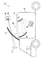
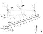
- FIG. 1 Schematic diagram of a vehicle equipped with a head-up display according to an embodiment of the present disclosure.
- Sectional drawing of the display device along the line BB of FIG. Perspective view of the first optical member and the second optical member as seen from the light guide panel side.
- Diagram showing the propagation of light through a prism array The figure which shows the propagation of the light of the side view of a display panel when the display panel is tilted with respect to the emission surface of a light guide panel.
- the figure which shows the propagation of the light in the short direction of the display panel when the full width at half maximum of the light transmitted through the display panel is about 30 degrees.
- the figure which shows the propagation of the light in the longitudinal direction of a display panel when the full width at half maximum of the light transmitted through the display panel is about 30 degrees.
- FIG. 1 is a schematic view of a vehicle equipped with a head-up display according to an embodiment of the present disclosure.
- the vehicle 10 is, for example, an automobile, and is equipped with a transparent windshield 12, that is, a head-up display 14 that projects light (image) onto a windshield.
- the light (video) output from the head-up display 14 is guided into the eyebox EB of the observer Ob, such as the driver boarding the vehicle 10, via the windshield 12.
- the observer Ob visually recognizes the virtual image Iv. That is, the observer Ob visually recognizes the landscape seen through the windshield 12 and the virtual image Iv overlapping the landscape.
- the eye box EB is a spatial area in which the observer Ob can visually recognize the virtual image Iv without missing it.
- the head-up display 14 has a housing 16. Inside the housing 16, a display device 20 and a plurality of mirrors 22 and 24 for guiding the light (video) output from the display device 20 to the windshield 12 are provided. For example, a convex mirror 22 that reflects the light output from the display device 20 and a concave mirror 24 that reflects the light from the convex mirror 22 toward the windshield 12 are provided in the housing 16.
- the windshield 12 and the plurality of mirrors 22 and 24 constitute a catadioptric system RS that guides the light output from the display device 20 to the eyebox EB of the observer Ob.
- the reflection optical system RS from the display device 20 to the eyebox EB differs depending on the vehicle mounting conditions of the head-up display 14.
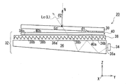
- FIG. 2 is a perspective view of the display device according to the embodiment of the present disclosure.
- FIG. 3 is a cross-sectional view of the display device along the line AA of FIG.
- FIG. 4 is a cross-sectional view of the display device along the line BB of FIG.
- the XYZ coordinate system shown in the figure is for facilitating the understanding of the present disclosure, and does not limit the present disclosure.
- the display device 20 includes a display panel 30 for displaying an image and a lighting device 32 for irradiating light toward the display panel 30.
- the display panel 30 is a transmissive liquid crystal panel. Further, in the case of the present embodiment, the display panel 30 has a rectangular shape including a longitudinal direction S1 (Y-axis direction) and a lateral direction S2 (X-axis direction). That is, the display panel 30 displays an image including a longitudinal direction and a lateral direction.
- the lighting device 32 has a plurality of light sources 34 and a light guide panel 36 that guides the light emitted from the plurality of light sources 34 toward the display panel 30.
- the plurality of light sources 34 are LEDs in the case of this embodiment.
- the number of light sources is not limited to 5, and may be 1 to 4 or 6 or more depending on the case.
- the light guide panel 36 is a panel-shaped member made of a transparent material such as a resin material.
- the light guide panel 36 includes an incident surface 36a facing the plurality of light sources 34, an emitting surface 36b facing the display panel 30, and a reflecting surface 36c facing the emitting surface 36b.
- the incident surface 36a is adjacent to the exit surface 36b perpendicularly (85 to 95 degrees).
- each of the plurality of light sources 34 faces the incident surface 36a of the light guide panel 36 in the longitudinal direction S1 (Y-axis direction) of the display panel 30. is doing. Further, a plurality of light sources 34 are arranged along the incident surface 36a in the lateral direction S2 (X-axis direction) of the display panel 30. The light emitted from each of the plurality of light sources 34 enters the light guide panel 36 via the incident surface 36a. The light that has entered is reflected a plurality of times by the exit surface 36b and the reflection surface 36c, and finally is emitted from the exit surface 36b.
- the emission surface 36b of the light guide panel 36 is a surface facing the display panel 30.
- the display panel 30 is arranged parallel to the exit surface 36b of the light guide panel 36. The light emitted from the emission surface 36b passes through the display panel 30 and finally reaches the eye box EB of the observer Ob.
- the display device 20 has a first optical member 38 and a second optical member 40 between the display panel 30 and the light guide panel 36.
- FIG. 5 is a perspective view of the first optical member and the second optical member as seen from the light guide panel side.
- the display panel 30 emits light L (image light) in a direction inclined with respect to the normal direction N, not in the normal direction N (Z-axis direction). Emit. Specifically, as shown in FIG. 3, the display panel is tilted by an angle ⁇ 2 (second angle) with respect to the normal direction N when viewed in the lateral direction S2 (X-axis direction) of the display panel 30. 30 emits light Lc. At the same time, as shown in FIG. 4, the display panel 30 is illuminated in a direction inclined by an angle ⁇ 5 (fifth angle) with respect to the normal direction N in the longitudinal direction S1 (Y-axis direction) of the display panel 30. Emit Lc.
- This light Lc is the center of the eye box EB (for example, the center of both eyes of the driver sitting in the driver's seat) from the center of the transmission region of the display panel 30 in the entire light L directed from the display panel 30 to the eye box EB. It is the light toward.
- the "transmissive region” referred to here is a region through which light can be transmitted and is a region in which an image (image) is formed. That is, the lighting device 32 emits the light L toward the display panel 30 at an inclination angle with respect to the normal direction N in this way. Due to this tilt angle, it is possible to prevent external light such as sunlight from being reflected by the display panel 30 and traveling on the optical path through which the light L of the lighting device 32 travels to finally reach the eyebox EB. ..
- the lighting device 32 is a first optical member that emits light Lc at a second angle ⁇ 2 with respect to the normal direction N of the display panel 30 when viewed in the lateral direction S2 (X-axis direction) of the display panel 30.
- the lighting device 32 includes a second optical member 40 that emits light Lc at a fifth angle ⁇ 5 with respect to the normal direction N of the display panel 30 when viewed in the longitudinal direction S1 (Y-axis direction) of the display panel 30.
- the first optical member 38 is a panel-shaped member made of a transparent material such as a resin material. Further, the first optical member 38 is arranged between the display panel 30 and the light guide panel 36, and the light L emitted from the emission surface 36b of the light guide panel 36 is incident.
- the first optical member 38 is provided with a prism array 38a on the surface of the incident surface facing the exit surface 36b of the light guide panel 36.
- the prism array 38a includes a plurality of prisms 38b parallel to each other in the longitudinal direction S1 (Y-axis direction) of the display panel 30 in the normal direction N (Z-axis direction) view of the display panel 30.
- the plurality of prisms 38b are arranged at a sufficiently large and equal pitch with respect to the wavelength of the light L.
- the first optical member 38 is incident with light L from the emission surface 36b of the light guide panel 36 by the prism array 38a, and emits the light from the emission surface 38c facing the display panel 30.
- the light L emitted from the first optical member 38 is emitted from the display panel 30 at the second angle ⁇ 2.
- the prism 38b of the prism array 38a is optically designed so that the light can be emitted at the second angle ⁇ 2.
- the absolute value of the second angle ⁇ 2 required for the light Lc from the center Cd of the transmission region of the display panel 30 toward the center of the eyebox EB is 0 ° ⁇
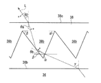
- FIG. 6 is a diagram showing the propagation of light through the prism array.
- the prism 38b of the prism array 38a of the first optical member 38 is a so-called triangular prism.
- the prism 38b has an emission angle ⁇ of the light L emitted from the emission surface 36b of the light guide panel 36 and a second angle required for the light Lc from the center Cd of the transmission region of the display panel 30 toward the center of the eyebox EB.
- the shape is designed based on ⁇ 2.
- ⁇ and ⁇ be the two angles formed by the two prism surfaces of the exit surface 38c and the prism 38b.
- the angle ⁇ is an angle that defines the inclination of the prism surface of the prism 38b on which the light L is incident.
- n be the refractive index of the prism 38b
- ⁇ a be the angle of incidence on the exit surface 38c
- ⁇ b be the angle of incidence on the prism surface between the angle ⁇ and the apex angle.
- the shape of the prism 38b can be determined.
- the prism 38b has, for example, an angle of 67 degrees. It is designed to have ⁇ and an angle ⁇ of 49.9 degrees. Further, when the second angle ⁇ 2 is ⁇ 30 degrees, the prism 38b is designed to include, for example, an angle ⁇ of 55 degrees and an angle ⁇ of 68.2 degrees.
- the display panel 30 is viewed on the light emitting surface 36b of the light guide panel 36 in the lighting device 32 in the lateral view (X-axis direction view) of the display panel 30. It may be arranged at an angle to the other.
- the display panel 30 is parallel to the emission surface 36b of the light guide panel 36 in the lighting device 32. That is, the first angle ⁇ 1 formed by the display panel 30 and the emission surface 36b of the light guide panel 36 is zero in the lateral view (X-axis direction view) of the display panel 30.
- the angles ⁇ and ⁇ of the prism 38b satisfying the following formulas 1A to 3A are determined.
- the emission angle ⁇ of the light guide panel 36 is 67 degrees
- the second angle ⁇ 2 is 20 degrees
- the first angle ⁇ 1 formed by the display panel and the emission surface 36b is 5 degrees
- the refractive index n of the prism 38b is 1.5.
- the prism 38b is designed to include, for example, an angle ⁇ of 67 degrees and an angle ⁇ of 51.5 degrees.
- the two angles ⁇ and ⁇ of the prism 38b are determined so as to be smaller than the second angle ⁇ 2 formed by the normal direction N of the display panel 30. The reason will be described later.
- the full width at half maximum of the light transmitted through the display panel 30 is about 30 degrees. Therefore, as shown in FIG. 7B, the light Lc required to move from the center Cd of the transmission region of the display panel 30 toward the center of the eyebox EB in the lateral direction (S2 (X-axis direction) view of the display panel 30).
- the angle ⁇ 3 (third angle) of the light L'actually emitted from the center Cd deviates by 3 degrees or more with respect to the second angle ⁇ 2, the brightness at the center of the eyebox EB changes.
- the angle ⁇ 3 of 3 is preferably in the range of ⁇ 3 degrees of the second angle ⁇ 2.
- the third angle ⁇ 3 is an angle with respect to the normal direction N as in the second angle ⁇ 2.
- each of the two angles of the prism 38b may not be one value, that is, a value within an appropriate range. That is, the two angles of the prism 38b may be values within an appropriate range centered on the angles ⁇ and ⁇ when the second angle ⁇ 2 and the third angle ⁇ 3 are equal.
- the prism 38b has, for example, an angle ⁇ of 67 degrees and an angle ⁇ of 50.9 degrees. Then, the display panel 30 may emit light L'at a third angle ⁇ 3 of 17 degrees.
- the prism 38b may have an angle ⁇ of 67 degrees and an angle ⁇ of 48.9 degrees, and the display panel 30 may emit light L'at a third angle ⁇ 3 of 23 degrees.
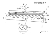
- the second optical member 40 is a panel-shaped member made of a transparent material such as a resin material. Further, the second optical member 40 is arranged between the display panel 30 and the first optical member 38, and the light L emitted from the first optical member 38 is incident on the second optical member 40.
- the second optical member 40 is provided with a Fresnel lens 40a on the surface of the light guide panel 36 facing the exit surface 36b via the first optical member 38. ing.
- the center Cf of the Fresnel lens 40a is deviated from the center Cd of the transmission region of the display panel 30 in the normal direction N view (Z-axis direction view) of the display panel 30.
- the center Cf of the Fresnel lens 40a is displaced by the deviation amount D with respect to the center Cd of the display panel 30 in the lateral direction S2 (X-axis direction) of the display panel 30.
- the second optical member 40 is tilted by a fifth angle ⁇ 5 with respect to the normal direction N from the exit surface 40b in the longitudinal direction S1 (Y-axis direction) of the display panel 30.
- Light L is emitted in the direction. Strictly speaking, the second optical member 40 emits light Lc from the center Cd of the transmission region of the display panel 30 toward the center of the eyebox EB at a fifth angle ⁇ 5 with respect to the normal direction N.
- the center Cf of the circle of the Fresnel lens 40a is deviated from the shape center of the second optical member 40 in the normal direction N view (Z-axis direction view) of the display panel 30. .. As shown in FIG. 5, the center Cf of the Fresnel lens 40a may be located on the second optical member 40, or may be located outside the second optical member 40 instead.
- the Fresnel lens 40a is optically designed based on the fifth angle ⁇ 5 required to move from the center Cd of the transmission region of the display panel 30 toward the center of the eyebox EB and the focal length F of the Fresnel lens. Specifically, the deviation amount D (center deviation amount) between the center Cf of the Fresnel lens 40a and the center Cd of the display panel 30 is determined.
- the center deviation amount D is 17. It is 5.5 mm.
- the display panel 30 in the longitudinal direction S1 view (Y-axis direction view) of the display panel 30, the display panel 30 is mounted on the emission surface 36b of the light guide panel 36 in the lighting device 32. It may be arranged at an angle to the other.
- the display panel 30 is parallel to the emission surface 36b of the light guide panel 36 in the lighting device 32. That is, the angle ⁇ 4 (fourth angle) formed by the display panel 30 and the emission surface 36b of the light guide panel 36 is zero in the longitudinal direction S1 view (Y-axis direction view) of the display panel 30.
- the fourth angle ⁇ 4 formed by the display panel 30 and the emission surface 36b of the light guide panel 36 is If it is not zero, the above formula 5 is replaced with the following formula 5A.
- the required fifth angle ⁇ 5 is 5 degrees
- the fourth angle ⁇ 4 formed by the display panel and the exit surface 36b is 1 degree
- the focal length F is 200 mm
- the center deviation amount D is 13.4 mm. Is.
- the fourth angle ⁇ 4 formed by the display panel 30 and the emission surface 36b of the light guide panel 36 is the light Lc directed from the center Cd of the transmission region of the display panel 30 toward the center of the eyebox EB.
- the center Cd of the transmission region of the display panel 30 and the center Cf of the Fresnel lens 40a are deviated from each other so as to be smaller than the fifth angle ⁇ 5 formed by the vertical direction N of the display panel 30. The reason will be described later.
- the full width at half maximum of the light transmitted through the display panel 30 is about 30 degrees. Therefore, as shown in FIG. 8B, the fifth angle ⁇ 5 required to move from the center Cd of the transmission region of the display panel 30 toward the center of the eyebox EB in the longitudinal direction S1 (Y-axis direction) of the display panel 30.
- the angle ⁇ 6 (sixth angle) of the light L'actually emitted from the center Cd deviates by 3 degrees or more, the brightness at the center of the eyebox EB changes. Therefore, the sixth angle ⁇ 6 is preferably in the range of ⁇ 3 degrees of the fifth angle ⁇ 5.
- the sixth angle ⁇ 6 is an angle with respect to the normal direction N, similarly to the fifth angle ⁇ 5.
- the amount of center deviation may not be one value, that is, a value within an appropriate range. That is, the center deviation amount may be a value within an appropriate range centered on the center deviation amount D when the fifth angle ⁇ 5 and the sixth angle ⁇ 6 are equal.
- the display panel 30 has the light L at the sixth angle ⁇ 6 of 2 degrees. May be emitted.
- the light L may be emitted by the display panel 30 at a sixth angle ⁇ 6 of 8 degrees with a center deviation amount of 28.1 mm.
- the display panel 30 and the lighting device 32 are transmitted while transmitting the light Lc of the lighting device 32 through the display panel 30 in a direction inclined with respect to the normal direction N of the display panel 30.
- the placement space can be reduced.
- FIG. 9 is a diagram showing a comparison between the display device according to the embodiment and the display device of the comparative example.
- the lighting device 132 in the display device of the comparative example is configured to emit light L in the normal direction of the emission surface 138c of the first optical member 138.
- the emission direction of the lighting device 132 is tilted with respect to the normal direction of the display panel 30. That is, the angle formed by the emission surface of the display panel 30 and the light guide panel 136 of the comparative example corresponding to the first angle ⁇ 1 (smaller than the second angle ⁇ 2) in the embodiment is relative to the second angle ⁇ 2.
- the lighting device 132 of the comparative example is larger by ⁇ V than the lighting device 32 of the present embodiment.
- a larger space is required as the arrangement space of the display panel 30 and the lighting device 132.
- the display device of the comparative example including the lighting device 132 is tilted in both the longitudinal direction S1 (Y-axis direction) and the lateral direction S2 (X-axis direction) of the display panel 30 with respect to the normal direction of the display panel 30.
- S1 Y-axis direction
- S2 X-axis direction
- a larger space is required as the arrangement space of the display panel 30 and the lighting device 132.
- the entire lighting device is the display panel. It is arranged substantially parallel to the relative. That is, the first angle ⁇ 1 shown in FIG. 7A is smaller than the second angle ⁇ 2, and similarly, the fourth angle ⁇ 4 shown in FIG. 8A is smaller than the fifth angle ⁇ 5.
- the space for arranging the display panel and the lighting device is smaller than that in the comparative example.
- FIG. 10 is a perspective view of a display device according to another embodiment.
- the display device 220 has a normal direction N only in the longitudinal direction S1 (Y-axis direction) of the display panel 30. It is configured to output the light L in a direction tilted with respect to the light L. Therefore, the illuminating device 232 includes a plurality of light sources 34, a light guide panel 36, and a first optical member 38, and does not include a second optical member 40.
- the display device is configured to output light L only in the lateral direction S2 (X-axis direction) of the display panel 30 in a direction inclined from the normal direction N. May be done.
- the display panel 30 is arranged parallel to or inclined with respect to the emission surface 36b of the light guide panel 36.
- the entire lighting device 32 is tilted with respect to the display panel 30, and in addition, the first optical member 38 and / or the second optical member 40 in the lighting device 32 tilts the light, so that the normal line is obtained.
- Light is emitted from the display panel 30 in a direction tilted by a required second and / or fifth angle with respect to the direction N.
- the space for arranging the display panel and the lighting device is smaller than in the case where the entire lighting device is tilted with respect to the display panel to realize the required second and / or fifth angles. That is, as shown in FIG.
- the first angle ⁇ 1 is made smaller than the second angle ⁇ 2, and / or, as shown in FIG. 8A, the fourth angle ⁇ 4 is made smaller than the fifth angle ⁇ 5. This reduces the space for arranging the display panel and the lighting device.
- the second angle ⁇ 2 is realized by the first optical member 38 as shown in FIG. 3, and the fifth angle ⁇ 5 is the second optical as shown in FIG. It is realized by the member 40.
- the second angle ⁇ 2 may be realized by both the first optical member 38 and the second optical member 40.
- the center Cd of the transmission region of the display panel 30 and the center Cf of the circle of the Fresnel lens 40a are displaced in both the longitudinal direction S1 (Y-axis direction) and the lateral direction S2 (X-axis direction) of the display panel 30.
- the center Cd of the transmission region of the display panel 30 and the center Cf of the Fresnel lens 40a may be displaced only in the longitudinal direction of the display panel 30 (in this case, the fifth angle ⁇ 5 becomes zero).
- the plurality of light sources 34 are arranged in the lateral direction S2 (X-axis direction) of the display panel 34.
- a plurality of light sources 34 may be arranged in the longitudinal direction S1 (Y-axis direction) of the display panel 30.
- the plurality of prisms of the prism array are arranged in parallel in the lateral direction S2 (X-axis direction) of the display panel 30.
- the head-up display 14 is mounted on a vehicle 10 such as an automobile.
- the moving body on which the head-up display is mounted is not limited to the vehicle.
- the moving body may be a vehicle on which a person rides, for example, an airplane or a ship.
- the mobile body may be an unmanned aerial vehicle.
- the moving body may be one that moves on the spot (for example, one that vibrates) rather than traveling.
- This disclosure is applicable to display devices.
- the present disclosure is also applicable to head-up displays.
Abstract
表示装置は、表示パネルと、照明装置を有する。照明装置は、光源と、光源の光を表示パネルに向かって出射する出射面を備える導光パネルと、導光パネルの出射面に対向するプリズムアレイを備える第1の光学部材とを含む。プリズムアレイが、表示パネルの法線方向視で、法線方向に対して直交する第1の方向に並列する複数のプリズムを含む。法線方向と第1の方向に対して直交する第2の方向視で、表示パネルと導光パネルとがなす第1の角度がアイボックスに向かう光と表示パネルの法線方向とがなす第2の角度に比べて小さくなるような角度を、プリズムは備える。
Description
本開示は、表示装置、表示装置を備えるヘッドアップディスプレイ、およびヘッドアップディスプレイを備える移動体に関する。
特許文献1には、車両に搭載されて表示装置を備えるヘッドアップディスプレイが開示されている。ヘッドアップディスプレイから出力された光(映像)は、ウインドシールドを介して、乗員(観察者)のアイボックス内に導かれる。
特許文献1に記載のヘッドアップディスプレイの表示装置は、照明装置(バックライト装置)と、映像を表示する透過型の表示パネル(液晶表示パネル)とを有する。表示パネルは、その法線方向が照明装置の光軸に対して所定の角度傾くように配置されている。すなわち、照明装置の光が、法線方向から所定の角度傾いた状態で表示パネルを透過する。その結果、例えば太陽光などの外光が表示パネルで反射し、その反射した外光が照明装置の光が進む光路上を進んで最終的にアイボックスに到達することを抑制している。
しかしながら、特許文献1に記載されたヘッドアップディスプレイの表示装置の場合、表示パネルが、その法線方向が照明装置の光の出射方向に対して傾くように配置されているために、これらの配置スペースが大きくなる。その結果、表示装置が大型化する。
そこで、本開示は、照明装置の光を表示パネルの法線方向に対して傾いた方向に該表示パネルを透過させつつ、表示パネルと照明装置の配置スペースを小さくすることを課題とする。
本開示の一態様によれば、
アイボックスに向かって映像光を出射する表示装置であって、
映像を表示する表示パネルと、
前記表示パネルに向かって光を照射する照明装置と、を有し、
前記照明装置が、
光を出射する光源、
前記光源からの光が入射され、前記表示パネルに向かって光を出射する出射面を備える導光パネル、および、
前記表示パネルと前記導光パネルとの間に配置され、前記導光パネルの出射面に対向する表面にプリズムアレイが設けられた入射面と、前記表示パネルに対向する出射面を備える第1の光学部材を含み、
前記プリズムアレイが、前記表示パネルの法線方向視で、前記法線方向に対して直交する第1の方向に並列する複数のプリズムを含み、
前記プリズムにおいて、
前記法線方向と前記第1の方向の両方に対して直交する第2の方向視で、前記出射面と2つのプリズム面それぞれとがなす2つのプリズムの角度は、前記表示パネルと前記導光パネルの出射面とがなす第1の角度が前記表示パネルの透過領域の中心から前記アイボックスの中心に向かう光と前記法線方向とがなす第2の角度に比べて小さくなるような角度である、表示装置が提供される。
本開示の異なる態様によれば、
上述の表示装置を有する、ヘッドアップディスプレイが提供される。
上述の表示装置を有する、ヘッドアップディスプレイが提供される。
本開示のさらに異なる態様によれば、
上述のヘッドアップディスプレイと、
前記ヘッドアップディスプレイから出力された映像が投影されるウインドシールドと、を有する、移動体が提供される。
上述のヘッドアップディスプレイと、
前記ヘッドアップディスプレイから出力された映像が投影されるウインドシールドと、を有する、移動体が提供される。
本開示によれば、照明装置の光を表示パネルの法線方向に対して傾いた方向に該表示パネルを透過させつつ、表示パネルと照明装置の配置スペースを小さくすることができる。
以下、適宜図面を参照しながら、実施の形態を詳細に説明する。但し、必要以上に詳細な説明は省略する場合がある。例えば、既によく知られた事項の詳細説明や実質的に同一の構成に対する重複説明を省略する場合がある。これは、以下の説明が不必要に冗長になるのを避け、当業者の理解を容易にするためである。
なお、発明者(ら)は、当業者が本開示を十分に理解するために添付図面および以下の説明を提供するのであって、これらによって特許請求の範囲に記載の主題を限定することを意図するものではない。
以下に、本開示の複数の実施の形態に係る表示装置について図1~図7を参照して説明する。
図1は、本開示の一実施の形態に係るヘッドアップディスプレイを搭載した車両の概略図である。
図1に示すように、車両10は、例えば自動車であって、透明のウインドシールド12、すなわちフロントガラスに光(映像)を投影するヘッドアップディスプレイ14を搭載している。
ヘッドアップディスプレイ14から出力された光(映像)は、ウインドシールド12を介して、車両10に搭乗する運転者などの観察者ObのアイボックスEB内に導かれる。これにより、観察者Obは虚像Ivを視認する。すなわち、ウインドシールド12を介して見える風景とそれに重なった虚像Ivとを、観察者Obは視認する。なお、アイボックスEBは、観察者Obが虚像Ivを欠けることなく視認できる空間領域である。
ヘッドアップディスプレイ14は、筐体16を有する。その筐体16内部に、表示装置20と、表示装置20から出力された光(映像)をウインドシールド12に導くための複数のミラー22、24とを有する。例えば、表示装置20から出力された光を反射する凸ミラー22と、凸ミラー22からの光をウインドシールド12に向かって反射する凹ミラー24とが筐体16内に設けられている。ウインドシールド12と、複数のミラー22、24が、表示装置20から出力された光を観察者ObのアイボックスEBに導く反射光学系RSを構成している。なお、表示装置20からアイボックスEBまでの反射光学系RSについては、ヘッドアップディスプレイ14の車両搭載条件によって異なる。
図2は、本開示の一実施の形態に係る表示装置の斜視図である。図3は、図2のA-A線に沿った表示装置の断面図である。図4は、図2のB-B線に沿った表示装置の断面図である。なお、図中において示すX-Y-Z座標系は、本開示の理解を容易にするためのものであって、本開示を限定するものではない。
図2および図3に示すように、本実施の形態に係る表示装置20は、映像を表示する表示パネル30と、表示パネル30に向かって光を照射する照明装置32とを有する。
表示パネル30は、本実施の形態の場合、透過型の液晶パネルである。また、本実施の形態の場合、表示パネル30は、長手方向S1(Y軸方向)と短手方向S2(X軸方向)とを備える矩形状である。すなわち、表示パネル30は、長手方向と短手方向とを備える映像を表示する。
照明装置32は、複数の光源34と、複数の光源34から出射された光を表示パネル30に向かって導光する導光パネル36とを有する。
複数の光源34は、本実施の形態の場合、LEDである。なお、光源の数は、5個に限らず、場合によっては1~4個または6個以上であってもよい。
導光パネル36は、透明な材料、例えば樹脂材料などから作製されたパネル状の部材である。具体的には、導光パネル36は、複数の光源34に対向する入射面36aと、表示パネル30に対向する出射面36bと、出射面36bに対向する反射面36cとを含んでいる。なお、本実施の形態の場合には、入射面36aは、出射面36bに対して垂直(85~95度)に隣接している。
本実施の形態の場合、図2および図3に示すように、導光パネル36の入射面36aに対して、複数の光源34それぞれは、表示パネル30の長手方向S1(Y軸方向)に対向している。また、入射面36aに沿うように、表示パネル30の短手方向S2(X軸方向)に、複数の光源34は並んでいる。複数の光源34それぞれから出射された光は、入射面36aを介して導光パネル36内に進入する。進入した光は、出射面36bと反射面36cで複数回反射され、最終的に出射面36bから出射する。
導光パネル36の出射面36bは、表示パネル30に対向する面である。本実施の形態の場合、表示パネル30が、導光パネル36の出射面36bに対して平行に配置されている。この出射面36bから出射された光は、表示パネル30を透過して最終的に観察者ObのアイボックスEBに到達する。
さらに、本実施の形態の場合、表示装置20は、表示パネル30と導光パネル36との間に、第1の光学部材38と、第2の光学部材40とを有する。
図5は、導光パネル側から見た第1の光学部材と第2の光学部材の斜視図である。
本実施の形態の場合、図2に示すように、表示パネル30は、その法線方向N(Z軸方向)ではなく、法線方向Nに対して傾いた方向に光L(映像光)を出射する。具体的には、図3に示すように、表示パネル30の短手方向S2(X軸方向)視で、法線方向Nに対して角度θ2(第2の角度)傾いた方向に、表示パネル30は光Lcを出射する。それとともに、図4に示すように、表示パネル30の長手方向S1(Y軸方向)視で、法線方向Nに対して角度φ5(第5の角度)傾いた方向に、表示パネル30は光Lcを出射する。この光Lcは、表示パネル30からアイボックスEBに向かう光Lの全体において、表示パネル30の透過領域の中心から、アイボックスEBの中心(例えば、運転席に着座する運転者の両目の中央)に向かう光である。ここで言う「透過領域」は、光が透過可能な領域であって、映像(画像)が形成される領域である。すなわち、このように法線方向Nに対する傾き角度で光Lを照明装置32が表示パネル30に向かって出射する。この傾き角度により、例えば太陽光などの外光が、表示パネル30で反射し、照明装置32の光Lが進む光路上を進んで最終的にアイボックスEBに到達することを抑制することができる。
そのために、照明装置32は、表示パネル30の短手方向S2(X軸方向)視で表示パネル30の法線方向Nに対して第2の角度θ2で光Lcを出射する第1の光学部材38を有する。また、照明装置32は、表示パネル30の長手方向S1(Y軸方向)視で表示パネル30の法線方向Nに対して第5の角度φ5で光Lcを出射する第2の光学部材40とを有する。
第1の光学部材38は、透明な材料、例えば樹脂材料などから作製されたパネル状の部材である。また、第1の光学部材38は、表示パネル30と導光パネル36との間に配置され、導光パネル36の出射面36bから出射された光Lが入射される。
さらに、第1の光学部材38は、図3および図5に示すように、導光パネル36の出射面36bに対向する入射面の表面に、プリズムアレイ38aが設けられている。プリズムアレイ38aは、表示パネル30の法線方向N(Z軸方向)視で、表示パネル30の長手方向S1(Y軸方向)に並列する複数のプリズム38bを含んでいる。複数のプリズム38bは、光Lの波長に対して十分に大きく且つ等しいピッチで並んでいる。
第1の光学部材38は、プリズムアレイ38aにより、導光パネル36の出射面36bからの光Lを入射し、その光を表示パネル30に対向する出射面38cから出射する。第1の光学部材38から出射した光Lは、第2の角度θ2で表示パネル30から出射する。この第2の角度θ2で出射できるように、プリズムアレイ38aのプリズム38bが光学設計されている。なお、表示パネル30の透過領域の中心CdからアイボックスEBの中心に向かう光Lcに必要な第2の角度θ2の絶対値は、0°<|θ2|≦45°である。
図6は、プリズムアレイを介する光の伝播を示す図である。
図6に示すように、第1の光学部材38のプリズムアレイ38aのプリズム38bは、いわゆる三角プリズムである。プリズム38bは、導光パネル36の出射面36bから出射される光Lの出射角γと、表示パネル30の透過領域の中心CdからアイボックスEBの中心に向かう光Lcに必要な第2の角度θ2とに基づいて、その形状が設計されている。
図6に示すように、まず、出射面38cとプリズム38bの2つのプリズム面とがなす2つの角度をα、βとする。一方の角度αは、光Lが入射するプリズム38bのプリズム面の傾きを定義する角度である。プリズム38bの屈折率をn、出射面38cに対する入射角をθa、角度αと頂角との間のプリズム面に対する入射角をθbとする。出射面38cに対してスネルの法則を適用すると、下記の数式1を得ることができる。

また、図6により、下記の角度関係式(数式2)を得ることができる。

さらに、角度αと頂角との間のプリズム面に対してスネルの法則を適用すると、下記の数式3を得ることができる。

これらの3つの数式1~数式3を用いることにより、プリズム38bの形状を決定することができる。
導光パネル36の出射角γが67度であって、第2の角度θ2が20度であって、プリズム38bの屈折率nが1.5の場合、プリズム38bは、例えば、67度の角度αと、49.9度の角度βとを備えるように設計される。また、第2の角度θ2が-30度である場合、プリズム38bは、例えば、55度の角度αと、68.2度の角度βとを備えるように設計される。
なお、別の実施の形態において、図7Aのように、表示パネル30の短手方向S2視(X軸方向視)で、表示パネル30は、照明装置32における導光パネル36の出射面36bに対して傾いて配置されてもよい。
図3に示す実施の形態の場合、表示パネル30は、照明装置32における導光パネル36の出射面36bに対して平行である。すなわち、表示パネル30の短手方向S2視(X軸方向視)で、表示パネル30と導光パネル36の出射面36bとがなす第1の角度θ1がゼロである。
図7Aに示す別の実施の形態のように、表示パネル30の短手方向S2視(X軸方向視)で、表示パネル30と導光パネル36の出射面36bとがなす角度θ1(第1の角度)がゼロでない場合、下記の数式1A~数式3Aを満足するプリズム38bの角度α、βが決定される。


なお、数式1~数式3は、θ1=0の場合の数式1A~数式3Aに対応する。
導光パネル36の出射角γが67度、第2の角度θ2が20度、表示パネルと出射面36bのなす第1の角度θ1が5度、そしてプリズム38bの屈折率nが1.5の場合、プリズム38bは、例えば、67度の角度αと、51.5度の角度βとを備えるように設計される。
また、図7Aに示すように、表示パネル30と導光パネル36の出射面36bとがなす第1の角度θ1が、表示パネル30の透過領域の中心CdからアイボックスEBの中心に向かう光Lcと表示パネル30の法線方向Nとがなす第2の角度θ2に比べて小さくなるように、プリズム38bの2つの角度α、βが決定されている。その理由については後述する。
また、ヘッドアップディスプレイの照明の特徴として表示パネル30を透過する光の半値全幅は約30度である。そのため、図7Bに示すように、表示パネル30の短手方向(S2(X軸方向)視で、表示パネル30の透過領域の中心CdからアイボックスEBの中心に向かうために必要な光Lcの第2の角度θ2に対して、実際に中心Cdから出射する光L’の角度θ3(第3の角度)が3度以上ずれると、アイボックスEBの中心での輝度が変化する。そのため、第3の角度θ3は、第2の角度θ2の±3度の範囲であることが好ましい。なお、第3の角度θ3は、第2の角度θ2と同様に、法線方向Nに対する角度である。
これは、プリズム38bの2つの角度それぞれが、1つの値ではなく、すなわち適当な範囲内の値でもよいことを意味する。すなわち、プリズム38bの2つの角度は、第2の角度θ2と第3の角度θ3とが等しい場合の角度α、βを中心値とする適当な範囲内の値であればよい。
例えば、必要とされる第2の角度θ2が20度である場合、プリズム38bの屈折率nが1.5のとき、プリズム38bが例えば67度の角度αと50.9度の角度βを有し、表示パネル30が17度の第3の角度θ3で光L’を出射してもよい。あるいは、プリズム38bが67度の角度αと48.9の角度βを有し、表示パネル30が23度の第3の角度θ3で光L’を出射してもよい。
このことを考慮した場合、下記の数式1B~数式3B、数式4を満足するプリズム38bの2つの角度α、βが決定される。


図4に戻って、第2の光学部材40は、透明な材料、例えば樹脂材料などから作製されたパネル状の部材である。また、第2の光学部材40は、表示パネル30と第1の光学部材38との間に配置され、第1の光学部材38から出射された光Lが入射される。
さらに、第2の光学部材40は、図4および図5に示すように、第1の光学部材38を介して、導光パネル36の出射面36bに対向する表面に、フレネルレンズ40aが設けられている。
本実施の形態の場合、表示パネル30の法線方向N視(Z軸方向視)で、フレネルレンズ40aの中心Cfは、表示パネル30の透過領域の中心Cdに対してずれている。具体的には、表示パネル30の短手方向S2(X軸方向)に、フレネルレンズ40aの中心Cfは、表示パネル30の中心Cdに対してずれ量Dでずれている。このような中心のずれにより、第2の光学部材40は、表示パネル30の長手方向S1(Y軸方向)視で、その出射面40bから法線方向Nに対して第5の角度φ5傾いた方向に光Lを出射する。厳密には、第2の光学部材40は、表示パネル30の透過領域の中心CdからアイボックスEBの中央に向かう光Lcを、法線方向Nに対する第5の角度φ5で出射する。
なお、本実施の形態の場合、表示パネル30の法線方向N視(Z軸方向視)で、第2の光学部材40の形状中心に対して、フレネルレンズ40aの円の中心Cfはずれている。なお、図5に示すように、フレネルレンズ40aの中心Cfは、第2の光学部材40上に位置してもよく、また代わりとして第2の光学部材40の外側に位置してもよい。
表示パネル30の透過領域の中心CdからアイボックスEBの中央に向かうために必要な第5の角度φ5とフレネルレンズの焦点距離Fに基づいて、フレネルレンズ40aが光学設計される。具体的には、フレネルレンズ40aの中心Cfと表示パネル30の中心Cdとの間のずれ量D(中心ずれ量)が決定される。
第5の角度φ5、中心ずれ量D、および焦点距離Fの関係は、下記の数式5によって表すことができる。

表示パネル30の透過領域の中心CdからアイボックスEBの中央に向かうために必要な第5の角度φ5が5度であって、焦点距離Fが200mmである場合、例えば、中心ずれ量Dは17.5mmである。
なお、別の実施の形態において、図8Aに示すように、表示パネル30の長手方向S1視(Y軸方向視)で、表示パネル30は、照明装置32における導光パネル36の出射面36bに対して傾いて配置されてもよい。
図4に示す実施の形態の場合、表示パネル30は、照明装置32における導光パネル36の出射面36bに対して平行である。すなわち、表示パネル30の長手方向S1視(Y軸方向視)で、表示パネル30と導光パネル36の出射面36bとがなす角度φ4(第4の角度)がゼロである。
図8Aに示す別の実施の形態のように、表示パネル30の長手方向S1視(Y軸方向視)で、表示パネル30と導光パネル36の出射面36bとがなす第4の角度φ4がゼロでない場合、上述の数式5が、下記の数式5Aに置き換わる。

なお、数式5は、φ4=0の場合の数式5Aに対応する。
必要な第5の角度φ5が5度であって、表示パネルと出射面36bのなす第4の角度φ4が1度であって、焦点距離Fが200mmの場合、中心ずれ量Dは13.4mmである。
また、図8Aに示すように、表示パネル30と導光パネル36の出射面36bとがなす第4の角度φ4が表示パネル30の透過領域の中心CdからアイボックスEBの中心に向かう光Lcと表示パネル30の垂直方向Nとがなす第5の角度φ5に比べて小さくなるように、表示パネル30の透過領域の中心Cdとフレネルレンズ40aの中心Cfとがずれている。その理由については後述する。
なお、ヘッドアップディスプレイの照明の特徴として表示パネル30を透過する光の半値全幅は約30度である。そのため、図8Bに示すように、表示パネル30の長手方向S1(Y軸方向)視で、表示パネル30の透過領域の中心CdからアイボックスEBの中央に向かうために必要な第5の角度φ5に対して、実際に中心Cdから出射する光L’の角度φ6(第6の角度)が3度以上ずれると、アイボックスEBの中心での輝度が変化する。そのため、第6の角度φ6は、第5の角度φ5の±3度の範囲であることが好ましい。なお、第6の角度φ6は、第5の角度φ5と同様に、法線方向Nに対する角度である。
これは、中心ずれ量が、1つの値ではなく、すなわち適当な範囲内の値でもよいことを意味する。すなわち、中心ずれ量は、第5の角度φ5と第6の角度φ6とが等しい場合の中心ずれ量Dを中心とする適当な範囲内の値であればよい。
例えば、必要とされる第5の角度φ5が5度であって、焦点距離Fが200mmの場合、中心ずれ量が6.7mmで、表示パネル30が2度の第6の角度φ6で光Lを出射してもよい。あるいは、中心ずれ量が28.1mmで、表示パネル30が8度の第6の角度φ6で光Lを出射してもよい。
このことを考慮した場合、下記の数式5Bおよび数式6を満足する中心ずれ量Dが決定される。


以上のような実施の形態によれば、照明装置32の光Lcを表示パネル30の法線方向Nに対して傾いた方向に該表示パネル30を透過させつつ、表示パネル30と照明装置32の配置スペースを小さくすることができる。
このことについて具体的に説明する。
図9は、実施の形態に係る表示装置と比較例の表示装置との比較を示す図である。
図9に示すように、比較例の表示装置における照明装置132は、その第1の光学部材138の出射面138cの法線方向に光Lを出射するように構成されている。この場合、表示パネル30から第2の角度θ2で光Lcを出射させるためには、表示パネル30の法線方向に対して照明装置132の出射方向が傾く必要がある。すなわち、実施の形態における第1の角度θ1(第2の角度θ2に比べて小さい)に対応する比較例の表示パネル30と導光パネル136の出射面のなす角度が第2の角度θ2に対して等しくなる。その結果、第2の角度θ2が大きくなればなるほど、図9に示す比較例の表示装置のように、表示パネル30と照明装置132の配置スペースとして、大きなスペースが必要になる(二点鎖線で示す本実施の形態の照明装置32と表示パネル30の配置スペースに比べて)。
また、図9に示すように、表示パネル30の各位置から出射される光Lは、拡散する必要がある。その結果、比較例の照明装置132は、本実施の形態の照明装置32に比べてΔVだけ大型化する。それにより、さらに、比較例の表示装置においては、表示パネル30と照明装置132の配置スペースとして、さらに大きなスペースが必要になる。
なお、照明装置132を備える比較例の表示装置が、表示パネル30の長手方向S1(Y軸方向)と短手方向S2(X軸方向)の両方に表示パネル30の法線方向に対して傾いた方向に光Lを出射する場合(第2の角度θ2および第5の角度φ5で光が出射される場合)、その表示パネル30と照明装置132の配置スペースとして、よりさらに大きなスペースが必要になる。
したがって、表示パネルがその法線方向に対して傾いた方向に光を出射するために、照明装置全体を表示パネルに対して傾ける比較例と異なり、本実施の形態では、照明装置全体が表示パネルに対して実質的に平行に配置される。すなわち、図7Aに示す第1の角度θ1が第2の角度θ2に比べて小さく、同様に、図8Aに示す第4の角度φ4が第5の角度φ5に比べて小さい。その結果、本実施の形態の場合、表示パネルと照明装置の配置スペースが、比較例に比べて小さくなる。
以上、上述の実施の形態を挙げて本開示を説明したが、本開示の実施の形態はこれに限定されない。
図10は、別の実施の形態に係る表示装置の斜視図である。
図10に示すように、別の実施の形態に係る表示装置220は、図2に示す上述の実施の形態と異なり、表示パネル30の長手方向S1(Y軸方向)のみにその法線方向Nに対して傾いた方向に光Lを出力するように構成されている。そのために、照明装置232は、複数の光源34、導光パネル36、および第1の光学部材38を備え、第2の光学部材40を備えていない。
なお、さらに別の実施の形態に係る表示装置として、表示パネル30の短手方向S2(X軸方向)のみにその法線方向Nから傾いた方向に光Lを出力するように表示装置が構成されてもよい。
また、上述したように、表示パネル30は、導光パネル36の出射面36bに対して平行または傾いて配置される。傾く場合、照明装置32全体が表示パネル30に対して傾くことにより、それに加えて照明装置32内の第1の光学部材38および/または第2の光学部材40が光を傾けることにより、法線方向Nに対して必要な第2および/または第5の角度だけ傾いた方向に表示パネル30から光が出射される。この場合も、照明装置全体が表示パネルに対して傾くのみで必要な第2および/または第5の角度を実現する場合に比べて、表示パネルと照明装置の配置スペースが小さくなる。すなわち、図7Aに示すように第1の角度θ1を第2の角度θ2に比べて小さくし、および/または、図8Aに示すように第4の角度φ4を第5の角度φ5に比べて小さくすれば、表示パネルと照明装置の配置スペースが小さくなる。
さらに、上述の実施の形態の場合、図3に示すように第2の角度θ2は、第1の光学部材38によって実現され、図4に示すように第5の角度φ5は、第2の光学部材40によって実現されている。しかしながら、本開示の実施の形態はこれに限らない。第2の角度θ2は、第1の光学部材38と第2の光学部材40の両方によって実現してもよい。この場合、表示パネル30の透過領域の中心Cdとフレネルレンズ40aの円の中心Cfとが、表示パネル30の長手方向S1(Y軸方向)と短手方向S2(X軸方向)の両方にずれている。なお、表示パネル30の透過領域の中心Cdとフレネルレンズ40aの中心Cfは表示パネル30の長手方向のみにずれてもよい(この場合、第5の角度φ5はゼロになる)。
さらにまた、上述の実施の形態の場合、複数の光源34は、表示パネル34の短手方向S2(X軸方向)に並んでいる。しかしながら、本開示の実施の形態はこれに限らない。複数の光源34が表示パネル30の長手方向S1(Y軸方向)に並んでもよい。この場合、プリズムアレイの複数のプリズムは、表示パネル30の短手方向S2(X軸方向)に並列する。
さらにまた、上述の実施の形態の場合、図1に示すように、ヘッドアップディスプレイ14は、自動車などの車両10に搭載されている。しかしながら、ヘッドアップディスプレイが搭載される移動体は車両に限らない。移動体は、人が乗る乗り物であってもよく、例えば、飛行機又は船であってもよい。移動体は、無人機であってもよい。移動体は、走行するようなものではなく、その場で可動するもの(例えば振動するもの)であってもよい。
以上のように、本開示における技術の例示として、複数の実施の形態を説明した。そのために、添付図面および詳細な説明を提供した。
したがって、添付図面および詳細な説明に記載された構成要素の中には、課題解決のために必須な構成要素だけでなく、前記技術を例示するために、課題解決のためには必須でない構成要素も含まれ得る。そのため、それらの必須ではない構成要素が添付図面や詳細な説明に記載されていることをもって、直ちに、それらの必須ではない構成要素が必須であるとの認定をするべきではない。
また、上述の実施の形態は、本開示における技術を例示するためのものであるから、請求の範囲またはその均等の範囲において種々の変更、置き換え、付加、省略などを行うことができる。
本開示は、表示装置に適用可能である。また、ヘッドアップディスプレイに本開示は適用可能である。
Claims (10)
- 観察者のアイボックスに向かって映像光を出射する表示装置であって、
映像を表示する表示パネルと、
前記表示パネルに向かって光を照射する照明装置と、を有し、
前記照明装置が、
光を出射する光源、
前記光源からの光が入射され、前記表示パネルに向かって光を出射する出射面を備える導光パネル、および、
前記表示パネルと前記導光パネルとの間に配置され、前記導光パネルの出射面に対向する表面にプリズムアレイが設けられた入射面と、前記表示パネルに対向する出射面とを備える第1の光学部材を含み、
前記プリズムアレイが、前記表示パネルの法線方向視で、前記法線方向に対して直交する第1の方向に並列する複数のプリズムを含み、
前記プリズムにおいて、
前記法線方向と前記第1の方向の両方に対して直交する第2の方向視で、前記出射面と2つのプリズム面それぞれとがなす2つのプリズムの角度は、前記表示パネルと前記導光パネルの出射面とがなす第1の角度が前記表示パネルの透過領域の中心から前記アイボックスの中心に向かう光と前記法線方向とがなす第2の角度に比べて小さくなるような角度である、表示装置。
- 前記第2の方向視で、前記導光パネルの出射角をγ、前記第1の角度をθ1、前記第2の角度をθ2、前記2つのプリズムの角度において前記導光パネルからの光が入射する前記プリズムのプリズム面の傾きを定義する一方のプリズムの角度をα、他方のプリズムの角度をβ、前記表示パネルの透過領域の中心から出射する光の前記法線方向に対する第3の角度をθ3、前記プリズムの屈折率をnとした場合、数式1~数式4を満たす、請求項1に記載の表示装置。


- 前記第2の角度θ2と前記第3の角度θ3とが等しい、請求項2に記載の表示装置。
- 前記照明装置が、
前記表示パネルと前記第1の光学部材との間に配置され、前記第1の光学部材の出射面に対向する表面にフレネルレンズが設けられ、前記表示パネルに対向する出射面を備える第2の光学部材を、さらに含み、
前記法線方向視で、前記表示パネルの透過領域の中心と前記フレネルレンズの中心とが、前記第1の方向および前記第2の方向の少なくとも一方にずれている、請求項1から3のいずれか一項に記載の表示装置。
- 前記第1の方向視で、前記表示パネルと前記導光パネルの出射面とがなす第4の角度が前記表示パネルの透過領域の中心から前記アイボックスの中心に向かう光と前記法線方向とがなす第5の角度に比べて小さくなるように、前記表示パネルの透過領域の中心と前記フレネルレンズの中心とが前記第2の方向にずれている、請求項4に記載の表示装置。
- 前記第1の方向視で、前記第4の角度をφ4、前記第5の角度をφ5、前記表示パネルの透過領域の中心から出射する光の前記法線方向に対する第6の傾き角度をφ6、前記フレネルレンズの焦点距離をF、前記表示パネルの透過領域の中心と前記フレネルレンズの中心と間のずれ量をDとした場合、数式5および6を満たす、請求項5に記載の表示装置。


- 前記第5の角度φ5と前記第6の角度φ6とが等しい、請求項6に記載の表示装置。
- 前記表示パネルが、前記導光パネルの出射面に対して平行に配置されている、請求項1から7のいずれか一項に記載の表示装置。
- 請求項1から8のいずれか一項に記載の表示装置を有するヘッドアップディスプレイ。
- 請求項9に記載のヘッドアップディスプレイと、
前記ヘッドアップディスプレイから出力された映像が投影されるウインドシールドと、を有する移動体。
Priority Applications (3)
| Application Number | Priority Date | Filing Date | Title |
|---|---|---|---|
| EP21817379.7A EP4163712A4 (en) | 2020-06-04 | 2021-02-24 | DISPLAY DEVICE, HEAD-UP DISPLAY AND MOBILE OBJECT |
| JP2022528435A JPWO2021246000A1 (ja) | 2020-06-04 | 2021-02-24 | |
| US18/071,831 US20230093703A1 (en) | 2020-06-04 | 2022-11-30 | Display device, head-up display, and mobile object |
Applications Claiming Priority (2)
| Application Number | Priority Date | Filing Date | Title |
|---|---|---|---|
| JP2020-097744 | 2020-06-04 | ||
| JP2020097744 | 2020-06-04 |
Related Child Applications (1)
| Application Number | Title | Priority Date | Filing Date |
|---|---|---|---|
| US18/071,831 Continuation US20230093703A1 (en) | 2020-06-04 | 2022-11-30 | Display device, head-up display, and mobile object |
Publications (1)
| Publication Number | Publication Date |
|---|---|
| WO2021246000A1 true WO2021246000A1 (ja) | 2021-12-09 |
Family
ID=78830791
Family Applications (1)
| Application Number | Title | Priority Date | Filing Date |
|---|---|---|---|
| PCT/JP2021/006900 WO2021246000A1 (ja) | 2020-06-04 | 2021-02-24 | 表示装置、ヘッドアップディスプレイ、および移動体 |
Country Status (4)
| Country | Link |
|---|---|
| US (1) | US20230093703A1 (ja) |
| EP (1) | EP4163712A4 (ja) |
| JP (1) | JPWO2021246000A1 (ja) |
| WO (1) | WO2021246000A1 (ja) |
Citations (4)
| Publication number | Priority date | Publication date | Assignee | Title |
|---|---|---|---|---|
| WO2007100458A1 (en) * | 2006-03-03 | 2007-09-07 | 3M Innovative Properties Company | Improved light control film composite and lcd device comprising the same |
| WO2017094209A1 (ja) * | 2015-11-30 | 2017-06-08 | パナソニックIpマネジメント株式会社 | 映像表示装置および映像表示装置を搭載したヘッドアップディスプレイ |
| WO2018088342A1 (ja) * | 2016-11-09 | 2018-05-17 | シャープ株式会社 | 表示装置及びヘッドマウントディスプレイ |
| JP2019101056A (ja) | 2017-11-28 | 2019-06-24 | 株式会社ジャパンディスプレイ | 表示装置およびヘッドアップ表示装置 |
Family Cites Families (1)
| Publication number | Priority date | Publication date | Assignee | Title |
|---|---|---|---|---|
| US7777960B2 (en) * | 2007-09-10 | 2010-08-17 | Microvision, Inc. | Wide field of view head-up display system |
-
2021
- 2021-02-24 WO PCT/JP2021/006900 patent/WO2021246000A1/ja unknown
- 2021-02-24 JP JP2022528435A patent/JPWO2021246000A1/ja active Pending
- 2021-02-24 EP EP21817379.7A patent/EP4163712A4/en active Pending
-
2022
- 2022-11-30 US US18/071,831 patent/US20230093703A1/en active Pending
Patent Citations (4)
| Publication number | Priority date | Publication date | Assignee | Title |
|---|---|---|---|---|
| WO2007100458A1 (en) * | 2006-03-03 | 2007-09-07 | 3M Innovative Properties Company | Improved light control film composite and lcd device comprising the same |
| WO2017094209A1 (ja) * | 2015-11-30 | 2017-06-08 | パナソニックIpマネジメント株式会社 | 映像表示装置および映像表示装置を搭載したヘッドアップディスプレイ |
| WO2018088342A1 (ja) * | 2016-11-09 | 2018-05-17 | シャープ株式会社 | 表示装置及びヘッドマウントディスプレイ |
| JP2019101056A (ja) | 2017-11-28 | 2019-06-24 | 株式会社ジャパンディスプレイ | 表示装置およびヘッドアップ表示装置 |
Non-Patent Citations (1)
| Title |
|---|
| See also references of EP4163712A4 |
Also Published As
| Publication number | Publication date |
|---|---|
| US20230093703A1 (en) | 2023-03-23 |
| EP4163712A1 (en) | 2023-04-12 |
| EP4163712A4 (en) | 2023-12-06 |
| JPWO2021246000A1 (ja) | 2021-12-09 |
Similar Documents
| Publication | Publication Date | Title |
|---|---|---|
| US11846776B2 (en) | Head-up display apparatus | |
| US9989760B2 (en) | Headup display device | |
| US8659840B2 (en) | Optical element, display apparatus, display method, and moving body | |
| US10901209B2 (en) | Head-up display device | |
| US9507152B2 (en) | Head-up display device | |
| US11155208B2 (en) | Image display unit | |
| JP7365621B2 (ja) | 結像光学系および結像光学系を搭載した移動体 | |
| US20160004081A1 (en) | Headup display device | |
| JP2015045808A (ja) | ヘッドアップディスプレイ装置 | |
| KR102215823B1 (ko) | 표시 장치 및 표시 방법 | |
| WO2021246000A1 (ja) | 表示装置、ヘッドアップディスプレイ、および移動体 | |
| US11867902B2 (en) | Display device, head-up display, moving body, and light guide panel | |
| US20240151955A1 (en) | Image projection device | |
| WO2021246001A1 (ja) | 表示装置、ヘッドアップディスプレイ、および移動体 | |
| JP2018180291A (ja) | 車両用表示装置 | |
| WO2020241218A1 (ja) | 投影装置及びヘッドアップディスプレイ | |
| US20200292800A1 (en) | Optical device | |
| JP7357233B2 (ja) | ヘッドアップディスプレイ | |
| JP7403105B2 (ja) | 映像表示装置および映像表示装置を搭載したヘッドアップディスプレイ、車両 | |
| JPWO2021246000A5 (ja) | ||
| JP2023173159A (ja) | ヘッドアップディスプレイ及び表示装置 | |
| WO2020059618A1 (ja) | ヘッドアップディスプレイ装置 | |
| WO2018173955A1 (ja) | 画像表示装置、虚像表示装置、移動体 | |
| JP2023173158A (ja) | ヘッドアップディスプレイ及び表示装置 | |
| JP2023167074A (ja) | 車両用表示装置 |
Legal Events
| Date | Code | Title | Description |
|---|---|---|---|
| 121 | Ep: the epo has been informed by wipo that ep was designated in this application |
Ref document number: 21817379 Country of ref document: EP Kind code of ref document: A1 |
|
| ENP | Entry into the national phase |
Ref document number: 2022528435 Country of ref document: JP Kind code of ref document: A |
|
| NENP | Non-entry into the national phase |
Ref country code: DE |
|
| ENP | Entry into the national phase |
Ref document number: 2021817379 Country of ref document: EP Effective date: 20230104 |