WO2021246000A1 - 表示装置、ヘッドアップディスプレイ、および移動体 - Google Patents
表示装置、ヘッドアップディスプレイ、および移動体 Download PDFInfo
- Publication number
- WO2021246000A1 WO2021246000A1 PCT/JP2021/006900 JP2021006900W WO2021246000A1 WO 2021246000 A1 WO2021246000 A1 WO 2021246000A1 JP 2021006900 W JP2021006900 W JP 2021006900W WO 2021246000 A1 WO2021246000 A1 WO 2021246000A1
- Authority
- WO
- WIPO (PCT)
- Prior art keywords
- display panel
- angle
- light
- display
- center
- Prior art date
- Legal status (The legal status is an assumption and is not a legal conclusion. Google has not performed a legal analysis and makes no representation as to the accuracy of the status listed.)
- Ceased
Links
Images





Classifications
-
- G—PHYSICS
- G02—OPTICS
- G02B—OPTICAL ELEMENTS, SYSTEMS OR APPARATUS
- G02B6/00—Light guides; Structural details of arrangements comprising light guides and other optical elements, e.g. couplings
- G02B6/0001—Light guides; Structural details of arrangements comprising light guides and other optical elements, e.g. couplings specially adapted for lighting devices or systems
- G02B6/0011—Light guides; Structural details of arrangements comprising light guides and other optical elements, e.g. couplings specially adapted for lighting devices or systems the light guides being planar or of plate-like form
- G02B6/0033—Means for improving the coupling-out of light from the light guide
- G02B6/005—Means for improving the coupling-out of light from the light guide provided by one optical element, or plurality thereof, placed on the light output side of the light guide
- G02B6/0053—Prismatic sheet or layer; Brightness enhancement element, sheet or layer
-
- B—PERFORMING OPERATIONS; TRANSPORTING
- B60—VEHICLES IN GENERAL
- B60K—ARRANGEMENT OR MOUNTING OF PROPULSION UNITS OR OF TRANSMISSIONS IN VEHICLES; ARRANGEMENT OR MOUNTING OF PLURAL DIVERSE PRIME-MOVERS IN VEHICLES; AUXILIARY DRIVES FOR VEHICLES; INSTRUMENTATION OR DASHBOARDS FOR VEHICLES; ARRANGEMENTS IN CONNECTION WITH COOLING, AIR INTAKE, GAS EXHAUST OR FUEL SUPPLY OF PROPULSION UNITS IN VEHICLES
- B60K35/00—Instruments specially adapted for vehicles; Arrangement of instruments in or on vehicles
- B60K35/20—Output arrangements, i.e. from vehicle to user, associated with vehicle functions or specially adapted therefor
- B60K35/21—Output arrangements, i.e. from vehicle to user, associated with vehicle functions or specially adapted therefor using visual output, e.g. blinking lights or matrix displays
- B60K35/23—Head-up displays [HUD]
-
- B—PERFORMING OPERATIONS; TRANSPORTING
- B60—VEHICLES IN GENERAL
- B60K—ARRANGEMENT OR MOUNTING OF PROPULSION UNITS OR OF TRANSMISSIONS IN VEHICLES; ARRANGEMENT OR MOUNTING OF PLURAL DIVERSE PRIME-MOVERS IN VEHICLES; AUXILIARY DRIVES FOR VEHICLES; INSTRUMENTATION OR DASHBOARDS FOR VEHICLES; ARRANGEMENTS IN CONNECTION WITH COOLING, AIR INTAKE, GAS EXHAUST OR FUEL SUPPLY OF PROPULSION UNITS IN VEHICLES
- B60K35/00—Instruments specially adapted for vehicles; Arrangement of instruments in or on vehicles
- B60K35/60—Instruments characterised by their location or relative disposition in or on vehicles
-
- G—PHYSICS
- G02—OPTICS
- G02B—OPTICAL ELEMENTS, SYSTEMS OR APPARATUS
- G02B27/00—Optical systems or apparatus not provided for by any of the groups G02B1/00 - G02B26/00, G02B30/00
- G02B27/01—Head-up displays
- G02B27/0101—Head-up displays characterised by optical features
-
- G—PHYSICS
- G02—OPTICS
- G02B—OPTICAL ELEMENTS, SYSTEMS OR APPARATUS
- G02B3/00—Simple or compound lenses
- G02B3/02—Simple or compound lenses with non-spherical faces
- G02B3/08—Simple or compound lenses with non-spherical faces with discontinuous faces, e.g. Fresnel lens
-
- B—PERFORMING OPERATIONS; TRANSPORTING
- B60—VEHICLES IN GENERAL
- B60K—ARRANGEMENT OR MOUNTING OF PROPULSION UNITS OR OF TRANSMISSIONS IN VEHICLES; ARRANGEMENT OR MOUNTING OF PLURAL DIVERSE PRIME-MOVERS IN VEHICLES; AUXILIARY DRIVES FOR VEHICLES; INSTRUMENTATION OR DASHBOARDS FOR VEHICLES; ARRANGEMENTS IN CONNECTION WITH COOLING, AIR INTAKE, GAS EXHAUST OR FUEL SUPPLY OF PROPULSION UNITS IN VEHICLES
- B60K2360/00—Indexing scheme associated with groups B60K35/00 or B60K37/00 relating to details of instruments or dashboards
- B60K2360/20—Optical features of instruments
- B60K2360/33—Illumination features
- B60K2360/334—Projection means
-
- G—PHYSICS
- G02—OPTICS
- G02B—OPTICAL ELEMENTS, SYSTEMS OR APPARATUS
- G02B6/00—Light guides; Structural details of arrangements comprising light guides and other optical elements, e.g. couplings
- G02B6/0001—Light guides; Structural details of arrangements comprising light guides and other optical elements, e.g. couplings specially adapted for lighting devices or systems
- G02B6/0011—Light guides; Structural details of arrangements comprising light guides and other optical elements, e.g. couplings specially adapted for lighting devices or systems the light guides being planar or of plate-like form
- G02B6/0033—Means for improving the coupling-out of light from the light guide
- G02B6/0035—Means for improving the coupling-out of light from the light guide provided on the surface of the light guide or in the bulk of it
- G02B6/0045—Means for improving the coupling-out of light from the light guide provided on the surface of the light guide or in the bulk of it by shaping at least a portion of the light guide
- G02B6/0046—Tapered light guide, e.g. wedge-shaped light guide
-
- G—PHYSICS
- G02—OPTICS
- G02B—OPTICAL ELEMENTS, SYSTEMS OR APPARATUS
- G02B6/00—Light guides; Structural details of arrangements comprising light guides and other optical elements, e.g. couplings
- G02B6/0001—Light guides; Structural details of arrangements comprising light guides and other optical elements, e.g. couplings specially adapted for lighting devices or systems
- G02B6/0011—Light guides; Structural details of arrangements comprising light guides and other optical elements, e.g. couplings specially adapted for lighting devices or systems the light guides being planar or of plate-like form
- G02B6/0033—Means for improving the coupling-out of light from the light guide
- G02B6/0058—Means for improving the coupling-out of light from the light guide varying in density, size, shape or depth along the light guide
-
- G—PHYSICS
- G02—OPTICS
- G02B—OPTICAL ELEMENTS, SYSTEMS OR APPARATUS
- G02B6/00—Light guides; Structural details of arrangements comprising light guides and other optical elements, e.g. couplings
- G02B6/0001—Light guides; Structural details of arrangements comprising light guides and other optical elements, e.g. couplings specially adapted for lighting devices or systems
- G02B6/0011—Light guides; Structural details of arrangements comprising light guides and other optical elements, e.g. couplings specially adapted for lighting devices or systems the light guides being planar or of plate-like form
- G02B6/0066—Light guides; Structural details of arrangements comprising light guides and other optical elements, e.g. couplings specially adapted for lighting devices or systems the light guides being planar or of plate-like form characterised by the light source being coupled to the light guide
- G02B6/0068—Arrangements of plural sources, e.g. multi-colour light sources
Definitions
- the present disclosure relates to a display device, a head-up display including a display device, and a mobile body including a head-up display.
- Patent Document 1 discloses a head-up display mounted on a vehicle and provided with a display device.
- the light (video) output from the head-up display is guided into the occupant's (observer's) eyebox via the windshield.
- the display device of the head-up display described in Patent Document 1 includes a lighting device (backlight device) and a transmissive display panel (liquid crystal display panel) for displaying an image.
- the display panel is arranged so that its normal direction is tilted at a predetermined angle with respect to the optical axis of the illuminating device. That is, the light of the lighting device passes through the display panel in a state of being tilted by a predetermined angle from the normal direction.
- external light such as sunlight is reflected by the display panel, and the reflected external light is suppressed from traveling on the optical path through which the light of the lighting device travels and finally reaching the eye box.
- an object of the present disclosure is to reduce the space for arranging the display panel and the lighting device while transmitting the light of the lighting device through the display panel in a direction inclined with respect to the normal direction of the display panel.
- a display device that emits video light toward the eyebox.
- a display panel that displays images and It has a lighting device that irradiates light toward the display panel.
- the lighting device A light source that emits light, A light guide panel having an exit surface on which light from the light source is incident and emits light toward the display panel, and A first unit that is arranged between the display panel and the light guide panel and has an incident surface having a prism array on the surface facing the emission surface of the light guide panel and an emission surface facing the display panel.
- the prism array includes a plurality of prisms parallel to each other in a first direction orthogonal to the normal direction in the normal direction of the display panel.
- the angle between the two prisms formed by the emission surface and each of the two prism surfaces is the angle between the display panel and the light guide.
- the first angle formed by the emission surface of the panel is smaller than the second angle formed by the light directed from the center of the transmission region of the display panel toward the center of the eyebox and the normal direction.
- a heads-up display with the display device described above is provided.
- a moving body having a windshield on which an image output from the head-up display is projected.
- the present disclosure it is possible to reduce the space for arranging the display panel and the lighting device while transmitting the light of the lighting device through the display panel in a direction inclined with respect to the normal direction of the display panel.
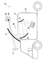
- FIG. 1 Schematic diagram of a vehicle equipped with a head-up display according to an embodiment of the present disclosure.
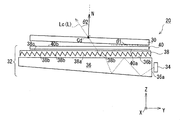
- Sectional drawing of the display device along the line BB of FIG. Perspective view of the first optical member and the second optical member as seen from the light guide panel side.
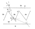
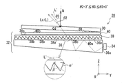
- Diagram showing the propagation of light through a prism array The figure which shows the propagation of the light of the side view of a display panel when the display panel is tilted with respect to the emission surface of a light guide panel.
- the figure which shows the propagation of the light in the short direction of the display panel when the full width at half maximum of the light transmitted through the display panel is about 30 degrees.
- the figure which shows the propagation of the light in the longitudinal direction of a display panel when the full width at half maximum of the light transmitted through the display panel is about 30 degrees.
- FIG. 1 is a schematic view of a vehicle equipped with a head-up display according to an embodiment of the present disclosure.
- the vehicle 10 is, for example, an automobile, and is equipped with a transparent windshield 12, that is, a head-up display 14 that projects light (image) onto a windshield.
- the light (video) output from the head-up display 14 is guided into the eyebox EB of the observer Ob, such as the driver boarding the vehicle 10, via the windshield 12.
- the observer Ob visually recognizes the virtual image Iv. That is, the observer Ob visually recognizes the landscape seen through the windshield 12 and the virtual image Iv overlapping the landscape.
- the eye box EB is a spatial area in which the observer Ob can visually recognize the virtual image Iv without missing it.
- the head-up display 14 has a housing 16. Inside the housing 16, a display device 20 and a plurality of mirrors 22 and 24 for guiding the light (video) output from the display device 20 to the windshield 12 are provided. For example, a convex mirror 22 that reflects the light output from the display device 20 and a concave mirror 24 that reflects the light from the convex mirror 22 toward the windshield 12 are provided in the housing 16.
- the windshield 12 and the plurality of mirrors 22 and 24 constitute a catadioptric system RS that guides the light output from the display device 20 to the eyebox EB of the observer Ob.
- the reflection optical system RS from the display device 20 to the eyebox EB differs depending on the vehicle mounting conditions of the head-up display 14.
- FIG. 2 is a perspective view of the display device according to the embodiment of the present disclosure.
- FIG. 3 is a cross-sectional view of the display device along the line AA of FIG.
- FIG. 4 is a cross-sectional view of the display device along the line BB of FIG.
- the XYZ coordinate system shown in the figure is for facilitating the understanding of the present disclosure, and does not limit the present disclosure.
- the display device 20 includes a display panel 30 for displaying an image and a lighting device 32 for irradiating light toward the display panel 30.
- the display panel 30 is a transmissive liquid crystal panel. Further, in the case of the present embodiment, the display panel 30 has a rectangular shape including a longitudinal direction S1 (Y-axis direction) and a lateral direction S2 (X-axis direction). That is, the display panel 30 displays an image including a longitudinal direction and a lateral direction.
- the lighting device 32 has a plurality of light sources 34 and a light guide panel 36 that guides the light emitted from the plurality of light sources 34 toward the display panel 30.
- the plurality of light sources 34 are LEDs in the case of this embodiment.
- the number of light sources is not limited to 5, and may be 1 to 4 or 6 or more depending on the case.
- the light guide panel 36 is a panel-shaped member made of a transparent material such as a resin material.
- the light guide panel 36 includes an incident surface 36a facing the plurality of light sources 34, an emitting surface 36b facing the display panel 30, and a reflecting surface 36c facing the emitting surface 36b.
- the incident surface 36a is adjacent to the exit surface 36b perpendicularly (85 to 95 degrees).
- each of the plurality of light sources 34 faces the incident surface 36a of the light guide panel 36 in the longitudinal direction S1 (Y-axis direction) of the display panel 30. is doing. Further, a plurality of light sources 34 are arranged along the incident surface 36a in the lateral direction S2 (X-axis direction) of the display panel 30. The light emitted from each of the plurality of light sources 34 enters the light guide panel 36 via the incident surface 36a. The light that has entered is reflected a plurality of times by the exit surface 36b and the reflection surface 36c, and finally is emitted from the exit surface 36b.
- the emission surface 36b of the light guide panel 36 is a surface facing the display panel 30.
- the display panel 30 is arranged parallel to the exit surface 36b of the light guide panel 36. The light emitted from the emission surface 36b passes through the display panel 30 and finally reaches the eye box EB of the observer Ob.
- the display device 20 has a first optical member 38 and a second optical member 40 between the display panel 30 and the light guide panel 36.
- FIG. 5 is a perspective view of the first optical member and the second optical member as seen from the light guide panel side.
- the display panel 30 emits light L (image light) in a direction inclined with respect to the normal direction N, not in the normal direction N (Z-axis direction). Emit. Specifically, as shown in FIG. 3, the display panel is tilted by an angle ⁇ 2 (second angle) with respect to the normal direction N when viewed in the lateral direction S2 (X-axis direction) of the display panel 30. 30 emits light Lc. At the same time, as shown in FIG. 4, the display panel 30 is illuminated in a direction inclined by an angle ⁇ 5 (fifth angle) with respect to the normal direction N in the longitudinal direction S1 (Y-axis direction) of the display panel 30. Emit Lc.
- This light Lc is the center of the eye box EB (for example, the center of both eyes of the driver sitting in the driver's seat) from the center of the transmission region of the display panel 30 in the entire light L directed from the display panel 30 to the eye box EB. It is the light toward.
- the "transmissive region” referred to here is a region through which light can be transmitted and is a region in which an image (image) is formed. That is, the lighting device 32 emits the light L toward the display panel 30 at an inclination angle with respect to the normal direction N in this way. Due to this tilt angle, it is possible to prevent external light such as sunlight from being reflected by the display panel 30 and traveling on the optical path through which the light L of the lighting device 32 travels to finally reach the eyebox EB. ..
- the lighting device 32 is a first optical member that emits light Lc at a second angle ⁇ 2 with respect to the normal direction N of the display panel 30 when viewed in the lateral direction S2 (X-axis direction) of the display panel 30.
- the lighting device 32 includes a second optical member 40 that emits light Lc at a fifth angle ⁇ 5 with respect to the normal direction N of the display panel 30 when viewed in the longitudinal direction S1 (Y-axis direction) of the display panel 30.
- the first optical member 38 is a panel-shaped member made of a transparent material such as a resin material. Further, the first optical member 38 is arranged between the display panel 30 and the light guide panel 36, and the light L emitted from the emission surface 36b of the light guide panel 36 is incident.
- the first optical member 38 is provided with a prism array 38a on the surface of the incident surface facing the exit surface 36b of the light guide panel 36.
- the prism array 38a includes a plurality of prisms 38b parallel to each other in the longitudinal direction S1 (Y-axis direction) of the display panel 30 in the normal direction N (Z-axis direction) view of the display panel 30.
- the plurality of prisms 38b are arranged at a sufficiently large and equal pitch with respect to the wavelength of the light L.
- the first optical member 38 is incident with light L from the emission surface 36b of the light guide panel 36 by the prism array 38a, and emits the light from the emission surface 38c facing the display panel 30.
- the light L emitted from the first optical member 38 is emitted from the display panel 30 at the second angle ⁇ 2.
- the prism 38b of the prism array 38a is optically designed so that the light can be emitted at the second angle ⁇ 2.
- the absolute value of the second angle ⁇ 2 required for the light Lc from the center Cd of the transmission region of the display panel 30 toward the center of the eyebox EB is 0 ° ⁇
- FIG. 6 is a diagram showing the propagation of light through the prism array.
- the prism 38b of the prism array 38a of the first optical member 38 is a so-called triangular prism.
- the prism 38b has an emission angle ⁇ of the light L emitted from the emission surface 36b of the light guide panel 36 and a second angle required for the light Lc from the center Cd of the transmission region of the display panel 30 toward the center of the eyebox EB.
- the shape is designed based on ⁇ 2.
- ⁇ and ⁇ be the two angles formed by the two prism surfaces of the exit surface 38c and the prism 38b.
- the angle ⁇ is an angle that defines the inclination of the prism surface of the prism 38b on which the light L is incident.
- n be the refractive index of the prism 38b
- ⁇ a be the angle of incidence on the exit surface 38c
- ⁇ b be the angle of incidence on the prism surface between the angle ⁇ and the apex angle.
- the shape of the prism 38b can be determined.
- the prism 38b has, for example, an angle of 67 degrees. It is designed to have ⁇ and an angle ⁇ of 49.9 degrees. Further, when the second angle ⁇ 2 is ⁇ 30 degrees, the prism 38b is designed to include, for example, an angle ⁇ of 55 degrees and an angle ⁇ of 68.2 degrees.
- the display panel 30 is viewed on the light emitting surface 36b of the light guide panel 36 in the lighting device 32 in the lateral view (X-axis direction view) of the display panel 30. It may be arranged at an angle to the other.
- the display panel 30 is parallel to the emission surface 36b of the light guide panel 36 in the lighting device 32. That is, the first angle ⁇ 1 formed by the display panel 30 and the emission surface 36b of the light guide panel 36 is zero in the lateral view (X-axis direction view) of the display panel 30.
- the angles ⁇ and ⁇ of the prism 38b satisfying the following formulas 1A to 3A are determined.
- the emission angle ⁇ of the light guide panel 36 is 67 degrees
- the second angle ⁇ 2 is 20 degrees
- the first angle ⁇ 1 formed by the display panel and the emission surface 36b is 5 degrees
- the refractive index n of the prism 38b is 1.5.
- the prism 38b is designed to include, for example, an angle ⁇ of 67 degrees and an angle ⁇ of 51.5 degrees.
- the two angles ⁇ and ⁇ of the prism 38b are determined so as to be smaller than the second angle ⁇ 2 formed by the normal direction N of the display panel 30. The reason will be described later.
- the full width at half maximum of the light transmitted through the display panel 30 is about 30 degrees. Therefore, as shown in FIG. 7B, the light Lc required to move from the center Cd of the transmission region of the display panel 30 toward the center of the eyebox EB in the lateral direction (S2 (X-axis direction) view of the display panel 30).
- the angle ⁇ 3 (third angle) of the light L'actually emitted from the center Cd deviates by 3 degrees or more with respect to the second angle ⁇ 2, the brightness at the center of the eyebox EB changes.
- the angle ⁇ 3 of 3 is preferably in the range of ⁇ 3 degrees of the second angle ⁇ 2.
- the third angle ⁇ 3 is an angle with respect to the normal direction N as in the second angle ⁇ 2.
- each of the two angles of the prism 38b may not be one value, that is, a value within an appropriate range. That is, the two angles of the prism 38b may be values within an appropriate range centered on the angles ⁇ and ⁇ when the second angle ⁇ 2 and the third angle ⁇ 3 are equal.
- the prism 38b has, for example, an angle ⁇ of 67 degrees and an angle ⁇ of 50.9 degrees. Then, the display panel 30 may emit light L'at a third angle ⁇ 3 of 17 degrees.
- the prism 38b may have an angle ⁇ of 67 degrees and an angle ⁇ of 48.9 degrees, and the display panel 30 may emit light L'at a third angle ⁇ 3 of 23 degrees.
- the second optical member 40 is a panel-shaped member made of a transparent material such as a resin material. Further, the second optical member 40 is arranged between the display panel 30 and the first optical member 38, and the light L emitted from the first optical member 38 is incident on the second optical member 40.
- the second optical member 40 is provided with a Fresnel lens 40a on the surface of the light guide panel 36 facing the exit surface 36b via the first optical member 38. ing.
- the center Cf of the Fresnel lens 40a is deviated from the center Cd of the transmission region of the display panel 30 in the normal direction N view (Z-axis direction view) of the display panel 30.
- the center Cf of the Fresnel lens 40a is displaced by the deviation amount D with respect to the center Cd of the display panel 30 in the lateral direction S2 (X-axis direction) of the display panel 30.
- the second optical member 40 is tilted by a fifth angle ⁇ 5 with respect to the normal direction N from the exit surface 40b in the longitudinal direction S1 (Y-axis direction) of the display panel 30.
- Light L is emitted in the direction. Strictly speaking, the second optical member 40 emits light Lc from the center Cd of the transmission region of the display panel 30 toward the center of the eyebox EB at a fifth angle ⁇ 5 with respect to the normal direction N.
- the center Cf of the circle of the Fresnel lens 40a is deviated from the shape center of the second optical member 40 in the normal direction N view (Z-axis direction view) of the display panel 30. .. As shown in FIG. 5, the center Cf of the Fresnel lens 40a may be located on the second optical member 40, or may be located outside the second optical member 40 instead.
- the Fresnel lens 40a is optically designed based on the fifth angle ⁇ 5 required to move from the center Cd of the transmission region of the display panel 30 toward the center of the eyebox EB and the focal length F of the Fresnel lens. Specifically, the deviation amount D (center deviation amount) between the center Cf of the Fresnel lens 40a and the center Cd of the display panel 30 is determined.
- the center deviation amount D is 17. It is 5.5 mm.
- the display panel 30 in the longitudinal direction S1 view (Y-axis direction view) of the display panel 30, the display panel 30 is mounted on the emission surface 36b of the light guide panel 36 in the lighting device 32. It may be arranged at an angle to the other.
- the display panel 30 is parallel to the emission surface 36b of the light guide panel 36 in the lighting device 32. That is, the angle ⁇ 4 (fourth angle) formed by the display panel 30 and the emission surface 36b of the light guide panel 36 is zero in the longitudinal direction S1 view (Y-axis direction view) of the display panel 30.
- the fourth angle ⁇ 4 formed by the display panel 30 and the emission surface 36b of the light guide panel 36 is If it is not zero, the above formula 5 is replaced with the following formula 5A.
- the required fifth angle ⁇ 5 is 5 degrees
- the fourth angle ⁇ 4 formed by the display panel and the exit surface 36b is 1 degree
- the focal length F is 200 mm
- the center deviation amount D is 13.4 mm. Is.
- the fourth angle ⁇ 4 formed by the display panel 30 and the emission surface 36b of the light guide panel 36 is the light Lc directed from the center Cd of the transmission region of the display panel 30 toward the center of the eyebox EB.
- the center Cd of the transmission region of the display panel 30 and the center Cf of the Fresnel lens 40a are deviated from each other so as to be smaller than the fifth angle ⁇ 5 formed by the vertical direction N of the display panel 30. The reason will be described later.
- the full width at half maximum of the light transmitted through the display panel 30 is about 30 degrees. Therefore, as shown in FIG. 8B, the fifth angle ⁇ 5 required to move from the center Cd of the transmission region of the display panel 30 toward the center of the eyebox EB in the longitudinal direction S1 (Y-axis direction) of the display panel 30.
- the angle ⁇ 6 (sixth angle) of the light L'actually emitted from the center Cd deviates by 3 degrees or more, the brightness at the center of the eyebox EB changes. Therefore, the sixth angle ⁇ 6 is preferably in the range of ⁇ 3 degrees of the fifth angle ⁇ 5.
- the sixth angle ⁇ 6 is an angle with respect to the normal direction N, similarly to the fifth angle ⁇ 5.
- the amount of center deviation may not be one value, that is, a value within an appropriate range. That is, the center deviation amount may be a value within an appropriate range centered on the center deviation amount D when the fifth angle ⁇ 5 and the sixth angle ⁇ 6 are equal.
- the display panel 30 has the light L at the sixth angle ⁇ 6 of 2 degrees. May be emitted.
- the light L may be emitted by the display panel 30 at a sixth angle ⁇ 6 of 8 degrees with a center deviation amount of 28.1 mm.
- the display panel 30 and the lighting device 32 are transmitted while transmitting the light Lc of the lighting device 32 through the display panel 30 in a direction inclined with respect to the normal direction N of the display panel 30.
- the placement space can be reduced.
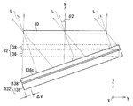
- FIG. 9 is a diagram showing a comparison between the display device according to the embodiment and the display device of the comparative example.
- the lighting device 132 in the display device of the comparative example is configured to emit light L in the normal direction of the emission surface 138c of the first optical member 138.
- the emission direction of the lighting device 132 is tilted with respect to the normal direction of the display panel 30. That is, the angle formed by the emission surface of the display panel 30 and the light guide panel 136 of the comparative example corresponding to the first angle ⁇ 1 (smaller than the second angle ⁇ 2) in the embodiment is relative to the second angle ⁇ 2.
- the lighting device 132 of the comparative example is larger by ⁇ V than the lighting device 32 of the present embodiment.
- a larger space is required as the arrangement space of the display panel 30 and the lighting device 132.
- the display device of the comparative example including the lighting device 132 is tilted in both the longitudinal direction S1 (Y-axis direction) and the lateral direction S2 (X-axis direction) of the display panel 30 with respect to the normal direction of the display panel 30.
- S1 Y-axis direction
- S2 X-axis direction
- a larger space is required as the arrangement space of the display panel 30 and the lighting device 132.
- the entire lighting device is the display panel. It is arranged substantially parallel to the relative. That is, the first angle ⁇ 1 shown in FIG. 7A is smaller than the second angle ⁇ 2, and similarly, the fourth angle ⁇ 4 shown in FIG. 8A is smaller than the fifth angle ⁇ 5.
- the space for arranging the display panel and the lighting device is smaller than that in the comparative example.
- FIG. 10 is a perspective view of a display device according to another embodiment.
- the display device 220 has a normal direction N only in the longitudinal direction S1 (Y-axis direction) of the display panel 30. It is configured to output the light L in a direction tilted with respect to the light L. Therefore, the illuminating device 232 includes a plurality of light sources 34, a light guide panel 36, and a first optical member 38, and does not include a second optical member 40.
- the display device is configured to output light L only in the lateral direction S2 (X-axis direction) of the display panel 30 in a direction inclined from the normal direction N. May be done.
- the display panel 30 is arranged parallel to or inclined with respect to the emission surface 36b of the light guide panel 36.
- the entire lighting device 32 is tilted with respect to the display panel 30, and in addition, the first optical member 38 and / or the second optical member 40 in the lighting device 32 tilts the light, so that the normal line is obtained.
- Light is emitted from the display panel 30 in a direction tilted by a required second and / or fifth angle with respect to the direction N.
- the space for arranging the display panel and the lighting device is smaller than in the case where the entire lighting device is tilted with respect to the display panel to realize the required second and / or fifth angles. That is, as shown in FIG.
- the first angle ⁇ 1 is made smaller than the second angle ⁇ 2, and / or, as shown in FIG. 8A, the fourth angle ⁇ 4 is made smaller than the fifth angle ⁇ 5. This reduces the space for arranging the display panel and the lighting device.
- the second angle ⁇ 2 is realized by the first optical member 38 as shown in FIG. 3, and the fifth angle ⁇ 5 is the second optical as shown in FIG. It is realized by the member 40.
- the second angle ⁇ 2 may be realized by both the first optical member 38 and the second optical member 40.
- the center Cd of the transmission region of the display panel 30 and the center Cf of the circle of the Fresnel lens 40a are displaced in both the longitudinal direction S1 (Y-axis direction) and the lateral direction S2 (X-axis direction) of the display panel 30.
- the center Cd of the transmission region of the display panel 30 and the center Cf of the Fresnel lens 40a may be displaced only in the longitudinal direction of the display panel 30 (in this case, the fifth angle ⁇ 5 becomes zero).
- the plurality of light sources 34 are arranged in the lateral direction S2 (X-axis direction) of the display panel 34.
- a plurality of light sources 34 may be arranged in the longitudinal direction S1 (Y-axis direction) of the display panel 30.
- the plurality of prisms of the prism array are arranged in parallel in the lateral direction S2 (X-axis direction) of the display panel 30.
- the head-up display 14 is mounted on a vehicle 10 such as an automobile.
- the moving body on which the head-up display is mounted is not limited to the vehicle.
- the moving body may be a vehicle on which a person rides, for example, an airplane or a ship.
- the mobile body may be an unmanned aerial vehicle.
- the moving body may be one that moves on the spot (for example, one that vibrates) rather than traveling.
- This disclosure is applicable to display devices.
- the present disclosure is also applicable to head-up displays.
Landscapes
- Physics & Mathematics (AREA)
- Engineering & Computer Science (AREA)
- General Physics & Mathematics (AREA)
- Optics & Photonics (AREA)
- Chemical & Material Sciences (AREA)
- Combustion & Propulsion (AREA)
- Transportation (AREA)
- Mechanical Engineering (AREA)
- Instrument Panels (AREA)
Priority Applications (3)
| Application Number | Priority Date | Filing Date | Title |
|---|---|---|---|
| EP21817379.7A EP4163712A4 (en) | 2020-06-04 | 2021-02-24 | DISPLAY DEVICE, HEAD-UP DISPLAY AND MOBILE OBJECT |
| JP2022528435A JP7630065B2 (ja) | 2020-06-04 | 2021-02-24 | 表示装置、ヘッドアップディスプレイ、および移動体 |
| US18/071,831 US20230093703A1 (en) | 2020-06-04 | 2022-11-30 | Display device, head-up display, and mobile object |
Applications Claiming Priority (2)
| Application Number | Priority Date | Filing Date | Title |
|---|---|---|---|
| JP2020097744 | 2020-06-04 | ||
| JP2020-097744 | 2020-06-04 |
Related Child Applications (1)
| Application Number | Title | Priority Date | Filing Date |
|---|---|---|---|
| US18/071,831 Continuation US20230093703A1 (en) | 2020-06-04 | 2022-11-30 | Display device, head-up display, and mobile object |
Publications (1)
| Publication Number | Publication Date |
|---|---|
| WO2021246000A1 true WO2021246000A1 (ja) | 2021-12-09 |
Family
ID=78830791
Family Applications (1)
| Application Number | Title | Priority Date | Filing Date |
|---|---|---|---|
| PCT/JP2021/006900 Ceased WO2021246000A1 (ja) | 2020-06-04 | 2021-02-24 | 表示装置、ヘッドアップディスプレイ、および移動体 |
Country Status (4)
| Country | Link |
|---|---|
| US (1) | US20230093703A1 (https=) |
| EP (1) | EP4163712A4 (https=) |
| JP (1) | JP7630065B2 (https=) |
| WO (1) | WO2021246000A1 (https=) |
Citations (4)
| Publication number | Priority date | Publication date | Assignee | Title |
|---|---|---|---|---|
| WO2007100458A1 (en) * | 2006-03-03 | 2007-09-07 | 3M Innovative Properties Company | Improved light control film composite and lcd device comprising the same |
| WO2017094209A1 (ja) * | 2015-11-30 | 2017-06-08 | パナソニックIpマネジメント株式会社 | 映像表示装置および映像表示装置を搭載したヘッドアップディスプレイ |
| WO2018088342A1 (ja) * | 2016-11-09 | 2018-05-17 | シャープ株式会社 | 表示装置及びヘッドマウントディスプレイ |
| JP2019101056A (ja) | 2017-11-28 | 2019-06-24 | 株式会社ジャパンディスプレイ | 表示装置およびヘッドアップ表示装置 |
Family Cites Families (1)
| Publication number | Priority date | Publication date | Assignee | Title |
|---|---|---|---|---|
| US7777960B2 (en) * | 2007-09-10 | 2010-08-17 | Microvision, Inc. | Wide field of view head-up display system |
-
2021
- 2021-02-24 JP JP2022528435A patent/JP7630065B2/ja active Active
- 2021-02-24 EP EP21817379.7A patent/EP4163712A4/en active Pending
- 2021-02-24 WO PCT/JP2021/006900 patent/WO2021246000A1/ja not_active Ceased
-
2022
- 2022-11-30 US US18/071,831 patent/US20230093703A1/en active Pending
Patent Citations (4)
| Publication number | Priority date | Publication date | Assignee | Title |
|---|---|---|---|---|
| WO2007100458A1 (en) * | 2006-03-03 | 2007-09-07 | 3M Innovative Properties Company | Improved light control film composite and lcd device comprising the same |
| WO2017094209A1 (ja) * | 2015-11-30 | 2017-06-08 | パナソニックIpマネジメント株式会社 | 映像表示装置および映像表示装置を搭載したヘッドアップディスプレイ |
| WO2018088342A1 (ja) * | 2016-11-09 | 2018-05-17 | シャープ株式会社 | 表示装置及びヘッドマウントディスプレイ |
| JP2019101056A (ja) | 2017-11-28 | 2019-06-24 | 株式会社ジャパンディスプレイ | 表示装置およびヘッドアップ表示装置 |
Non-Patent Citations (1)
| Title |
|---|
| See also references of EP4163712A4 |
Also Published As
| Publication number | Publication date |
|---|---|
| JPWO2021246000A1 (https=) | 2021-12-09 |
| US20230093703A1 (en) | 2023-03-23 |
| EP4163712A4 (en) | 2023-12-06 |
| JP7630065B2 (ja) | 2025-02-17 |
| EP4163712A1 (en) | 2023-04-12 |
Similar Documents
| Publication | Publication Date | Title |
|---|---|---|
| US9989760B2 (en) | Headup display device | |
| EP2372407A2 (en) | Optical element with a Fresnel lens, display apparatus, display method, and moving body | |
| JP6601431B2 (ja) | ヘッドアップディスプレイ装置 | |
| JP7715889B2 (ja) | ヘッドアップディスプレイ | |
| JP7365621B2 (ja) | 結像光学系および結像光学系を搭載した移動体 | |
| US9507152B2 (en) | Head-up display device | |
| CN107238927A (zh) | 车辆用投影显示设备 | |
| US11155208B2 (en) | Image display unit | |
| US20160004081A1 (en) | Headup display device | |
| JP2015045808A (ja) | ヘッドアップディスプレイ装置 | |
| US20240151955A1 (en) | Image projection device | |
| KR102215823B1 (ko) | 표시 장치 및 표시 방법 | |
| US11867902B2 (en) | Display device, head-up display, moving body, and light guide panel | |
| JP2018180291A (ja) | 車両用表示装置 | |
| US12072488B2 (en) | Display device, head-up display, and mobile object | |
| JP7630065B2 (ja) | 表示装置、ヘッドアップディスプレイ、および移動体 | |
| WO2020241218A1 (ja) | 投影装置及びヘッドアップディスプレイ | |
| JP7403105B2 (ja) | 映像表示装置および映像表示装置を搭載したヘッドアップディスプレイ、車両 | |
| WO2018173955A1 (ja) | 画像表示装置、虚像表示装置、移動体 | |
| US20200292800A1 (en) | Optical device | |
| JP7839546B2 (ja) | ヘッドアップディスプレイ及び表示装置 | |
| US12576780B2 (en) | Light source device | |
| JP7357233B2 (ja) | ヘッドアップディスプレイ | |
| JP2023173159A (ja) | ヘッドアップディスプレイ及び表示装置 | |
| JPWO2021246000A5 (https=) |
Legal Events
| Date | Code | Title | Description |
|---|---|---|---|
| 121 | Ep: the epo has been informed by wipo that ep was designated in this application |
Ref document number: 21817379 Country of ref document: EP Kind code of ref document: A1 |
|
| ENP | Entry into the national phase |
Ref document number: 2022528435 Country of ref document: JP Kind code of ref document: A |
|
| NENP | Non-entry into the national phase |
Ref country code: DE |
|
| ENP | Entry into the national phase |
Ref document number: 2021817379 Country of ref document: EP Effective date: 20230104 |