WO2021245976A1 - 流量測定装置 - Google Patents
流量測定装置 Download PDFInfo
- Publication number
- WO2021245976A1 WO2021245976A1 PCT/JP2021/003178 JP2021003178W WO2021245976A1 WO 2021245976 A1 WO2021245976 A1 WO 2021245976A1 JP 2021003178 W JP2021003178 W JP 2021003178W WO 2021245976 A1 WO2021245976 A1 WO 2021245976A1
- Authority
- WO
- WIPO (PCT)
- Prior art keywords
- passage
- sub
- gas
- measured
- flow rate
- Prior art date
- Legal status (The legal status is an assumption and is not a legal conclusion. Google has not performed a legal analysis and makes no representation as to the accuracy of the status listed.)
- Ceased
Links
Images


Classifications
-
- G—PHYSICS
- G01—MEASURING; TESTING
- G01F—MEASURING VOLUME, VOLUME FLOW, MASS FLOW OR LIQUID LEVEL; METERING BY VOLUME
- G01F5/00—Measuring a proportion of the volume flow
- G01F5/005—Measuring a proportion of the volume flow by measuring pressure or differential pressure, created by the use of flow constriction
-
- G—PHYSICS
- G01—MEASURING; TESTING
- G01F—MEASURING VOLUME, VOLUME FLOW, MASS FLOW OR LIQUID LEVEL; METERING BY VOLUME
- G01F1/00—Measuring the volume flow or mass flow of fluid or fluent solid material wherein the fluid passes through a meter in a continuous flow
- G01F1/68—Measuring the volume flow or mass flow of fluid or fluent solid material wherein the fluid passes through a meter in a continuous flow by using thermal effects
- G01F1/684—Structural arrangements; Mounting of elements, e.g. in relation to fluid flow
-
- G—PHYSICS
- G01—MEASURING; TESTING
- G01F—MEASURING VOLUME, VOLUME FLOW, MASS FLOW OR LIQUID LEVEL; METERING BY VOLUME
- G01F1/00—Measuring the volume flow or mass flow of fluid or fluent solid material wherein the fluid passes through a meter in a continuous flow
- G01F1/05—Measuring the volume flow or mass flow of fluid or fluent solid material wherein the fluid passes through a meter in a continuous flow by using mechanical effects
- G01F1/34—Measuring the volume flow or mass flow of fluid or fluent solid material wherein the fluid passes through a meter in a continuous flow by using mechanical effects by measuring pressure or differential pressure
- G01F1/36—Measuring the volume flow or mass flow of fluid or fluent solid material wherein the fluid passes through a meter in a continuous flow by using mechanical effects by measuring pressure or differential pressure the pressure or differential pressure being created by the use of flow constriction
- G01F1/40—Details of construction of the flow constriction devices
-
- G—PHYSICS
- G01—MEASURING; TESTING
- G01F—MEASURING VOLUME, VOLUME FLOW, MASS FLOW OR LIQUID LEVEL; METERING BY VOLUME
- G01F1/00—Measuring the volume flow or mass flow of fluid or fluent solid material wherein the fluid passes through a meter in a continuous flow
- G01F1/68—Measuring the volume flow or mass flow of fluid or fluent solid material wherein the fluid passes through a meter in a continuous flow by using thermal effects
- G01F1/684—Structural arrangements; Mounting of elements, e.g. in relation to fluid flow
- G01F1/6842—Structural arrangements; Mounting of elements, e.g. in relation to fluid flow with means for influencing the fluid flow
-
- G—PHYSICS
- G01—MEASURING; TESTING
- G01F—MEASURING VOLUME, VOLUME FLOW, MASS FLOW OR LIQUID LEVEL; METERING BY VOLUME
- G01F5/00—Measuring a proportion of the volume flow
Definitions
- Patent Document 1 The technique of Patent Document 1 is disclosed as an example of a flow rate measuring device.
- An object of the present invention is to provide a flow rate measuring device capable of improving the stain resistance and accurately measuring the flow rate of the gas to be measured.
- the gas to be measured is between a first passage portion having a first gap through which the gas to be measured passes and a passage wall surface of the sub-passage facing the other surface of the substrate and the other surface of the substrate.
- a second passage portion having a second gap through which the gas to be measured passes, and a third gap through which the gas to be measured passes between the support and the passage wall surface of the sub-passage facing the support. It has three passage portions, and the support is characterized by having side surfaces facing the flow direction of the gas to be measured in the sub passage.
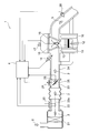
- FIG. 1 is a system diagram showing an embodiment in which a physical quantity detection device according to the present embodiment is used in an electronic fuel injection type internal combustion engine control system 1.
- the intake air is sucked from the air cleaner 21 as the measured gas 2, and the intake body, for example, the throttle body 23, and the intake manifold 24, which are the main passages 22, are formed. It is guided to the combustion chamber of the engine cylinder 11 via the engine.
- the physical quantity of the gas to be measured 2 which is the intake air guided to the combustion chamber is detected by the physical quantity detection device 20, fuel is supplied from the fuel injection valve 14 based on the detected physical quantity, and the air-fuel mixture is supplied together with the gas to be measured 2.
- the fuel injection valve 14 is provided in the intake port of the internal combustion engine, and the fuel injected into the intake port forms an air-fuel mixture together with the gas to be measured 2 and is guided to the combustion chamber via the intake valve 15. It burns and generates mechanical energy.
- the fuel and air guided to the combustion chamber are in a mixed state of fuel and air, and are explosively burned by the spark ignition of the spark plug 13 to generate mechanical energy.
- the gas after combustion is guided to the exhaust pipe from the exhaust valve 16 and is discharged to the outside of the vehicle from the exhaust pipe as exhaust gas 3.
- the flow rate of the gas to be measured 2 which is the intake air guided to the combustion chamber is controlled by the throttle valve 25 whose opening degree changes based on the operation of the accelerator pedal.
- the fuel supply amount is controlled based on the flow rate of the intake air guided to the combustion chamber, and the driver controls the opening degree of the throttle valve 25 to control the flow rate of the intake air guided to the combustion chamber, thereby internal combustion.
- the mechanical energy generated by the engine can be controlled.
- the control device 4 calculates the fuel injection amount and the ignition timing based on the physical quantity of the intake air which is the output of the physical quantity detection device 20 and the rotation speed of the internal combustion engine measured based on the output of the rotation angle sensor 17. Based on these calculation results, the amount of fuel supplied from the fuel injection valve 14 and the ignition timing ignited by the spark plug 13 are controlled. The fuel supply amount and ignition timing are actually based on the state of change in temperature and throttle angle detected by the physical quantity detection device 20, the state of change in engine rotation speed, and the state of air-fuel ratio measured by the oxygen sensor 28. It is finely controlled. Further, the control device 4 controls the amount of air bypassing the throttle valve 25 by the idle air control valve 27 in the idle operation state of the internal combustion engine, and controls the rotation speed of the internal combustion engine in the idle operation state.
- the fuel supply amount and ignition timing which are the main control amounts of the internal combustion engine, are both calculated using the output of the physical quantity detection device 20 as the main parameter. Therefore, it is important to improve the detection accuracy of the physical quantity detecting device 20, suppress the change with time, and improve the reliability in order to improve the control accuracy and the reliability of the vehicle.
- the vehicle equipped with the physical quantity detection device 20 is used in an environment where changes in temperature and humidity are large. It is desirable that the physical quantity detecting device 20 also considers the response to changes in temperature and humidity in the usage environment and the response to dust and pollutants.
- the physical quantity detecting device 20 is mounted on the intake pipe which is affected by the heat generated from the internal combustion engine. Therefore, the heat generated by the internal combustion engine is transmitted to the physical quantity detecting device 20 via the intake pipe. Since the physical quantity detecting device 20 detects the flow rate of the measured gas by conducting heat transfer with the measured gas, it is important to suppress the influence of heat from the outside as much as possible.
- the physical quantity detecting device 20 mounted on the vehicle simply solves the problems described in the column of the problems to be solved by the invention, and merely exerts the effects described in the column of the effects of the invention. Instead, as explained below, the various problems described above are fully considered, the various problems required for the product are solved, and various effects are achieved. Specific problems to be solved by the physical quantity detecting device 20 and specific effects to be achieved will be described in the description of the following examples.
- the physical quantity detecting device 20 is used in a state of being inserted into the inside of the main passage 22 through an attachment hole provided in the passage wall of the main passage 22 and fixed to the main passage 22.
- the physical quantity detecting device 20 includes a housing arranged in the main passage 22 through which the gas to be measured flows.
- the housing of the physical quantity detecting device 20 has a housing 100 and a cover 200 attached to the housing 100.
- the housing 100 is configured, for example, by injection molding a synthetic resin material.
- the housing 100 has a flange 111 for fixing the physical quantity detecting device 20 to the intake body which is the main passage 22, and a connector which protrudes from the flange 111 and is exposed to the outside from the intake body for making an electrical connection with an external device. It has 112 and a measuring unit 113 extending from the flange 111 toward the center of the main passage 22.
- the measuring unit 113 is inserted inside through a mounting hole provided in the main passage 22, the flange 111 of the physical quantity detecting device 20 is brought into contact with the main passage 22, and is fixed to the main passage 22 with screws.
- the measuring unit 113 has a thin and long shape extending straight from the flange 111, and has a wide front surface 121 and a back surface 122, and a pair of narrow side surfaces 123 and 124.
- the measuring unit 113 projects from the inner wall of the main passage 22 toward the center of the passage 22 in a state where the physical quantity detecting device 20 is attached to the main passage 22.
- the front surface 121 and the back surface 122 are arranged in parallel along the central axis 22A of the main passage 22, and the side surface 123 on one side in the longitudinal direction of the measurement unit 113 among the narrow side surfaces 123 and 124 of the measurement unit 113 is the main passage. 22 is arranged to face the upstream side (air cleaner side), and the side surface 124 on the other side in the lateral direction of the measuring unit 113 is arranged to face the downstream side (engine side) of the main passage 22.
- the axis in the longitudinal direction of the measuring unit 113 which is the direction in which the measuring unit 113 extends from the flange 111, is the Z axis, and the measuring unit in the direction extending from the sub-passage inlet 131 of the measuring unit 113 toward the first exit 132.
- the axis in the lateral direction of 113 may be referred to as the X axis
- the axis in the thickness direction of the measurement unit 113 in the direction from the front surface 121 to the back surface 122 of the measurement unit 113 may be referred to as the Y axis.
- the measuring unit 113 is provided with a sub-passage inlet 131 on the side surface 123 on one side in the X-axis direction, and a first exit 132 and a second exit 133 on the side surface 124 on the other side in the X-axis direction.
- the sub-passage inlet 131, the first outlet 132, and the second outlet 133 are provided at the tip of the measuring unit 113 extending from the flange 111 toward the center of the main passage 22 in the Z-axis direction. Therefore, of the gas to be measured 2 flowing through the main passage 22, the gas to be measured 2 in the portion near the central portion away from the inner wall surface of the main passage 22 can be taken into the sub-passage 134. Therefore, the physical quantity detecting device 20 can measure the flow rate of the gas to be measured 2 in the portion away from the inner wall surface of the main passage 22, and can suppress the deterioration of the measurement accuracy due to the influence of heat or the like.
- the measuring unit 113 has a shape in which the measuring unit 113 extends long along the Z axis toward the center from the outer wall of the main passage 22, but the widths of the side surfaces 123 and 124 in the Y-axis direction are narrow. ing. As a result, the physical quantity detecting device 20 can suppress the fluid resistance to a small value with respect to the gas to be measured 2.
- the measuring unit 113 is inserted inside through a mounting hole provided in the main passage 22, the flange 111 is brought into contact with the main passage 22, and is fixed to the main passage 22 with screws.
- the flange 111 has a substantially rectangular shape in a plan view having a predetermined plate thickness, and as shown in FIGS. 6 and 7, fixed hole portions 141 are provided in pairs at the diagonal corner portions. There is.
- the fixing hole portion 141 has a through hole 142 penetrating the flange 111.
- the flange 111 is fixed to the main passage 22 by inserting a fixing screw (not shown) into the through hole 142 of the fixing hole portion 141 and screwing it into the screw hole of the main passage 22.
- the connector 112 is provided with three external terminals 147 and a correction terminal 148 inside.
- the external terminal 147 is a terminal for outputting a physical quantity such as a flow rate and a temperature, which is a measurement result of the physical quantity detecting device 20, and a power supply terminal for supplying DC power for operating the physical quantity detecting device 20.
- the correction terminal 148 is a terminal used to measure the produced physical quantity detection device 20, obtain a correction value for each physical quantity detection device 20, and store the correction value in the memory inside the physical quantity detection device 20. In the subsequent measurement operation of the physical quantity detecting device 20, the correction data representing the correction value stored in the above-mentioned memory is used, and the correction terminal 148 is not used.
- FIG. 8 is a sectional view taken along line VIII-VIII of FIG. 4
- FIG. 9 is a sectional view taken along line IX-IX of FIG. 2
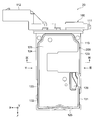
- FIG. 10 is a view showing a state in which the cover of the physical quantity detecting device shown in FIG. 2 is removed.
- 11 is a diagram showing a state in which the circuit board is removed from the physical quantity detection device shown in FIG. 10
- FIG. 12 is a diagram showing a state before sealing the opening window of the physical quantity detection device shown in FIG.
- the measurement unit 113 of the housing 100 is provided with a flow rate sensor 411, which is a flow rate detection element, an intake air temperature sensor 321 and a humidity sensor 322.
- the flow rate sensor 411 detects the flow rate of the gas to be measured 2 flowing through the main passage.
- the flow rate sensor 411 has a diaphragm structure and is arranged in the middle of the sub-passage 134.
- the intake air temperature sensor 321 is arranged in the middle of the passage of the temperature detection passage 136, one end of which is open near the sub-passage inlet 131 of the side surface 123 and the other end of which is open on both the front surface 121 and the back surface of the measurement unit 113.
- the intake air temperature sensor 321 detects the temperature of the gas to be measured 2 flowing through the main passage.
- the humidity sensor 322 is arranged in the humidity measurement room 137 of the measurement unit 113.
- the humidity sensor 322 measures the humidity of the gas to be measured taken into the humidity measuring chamber 137 from the window portion 138 opening on the back surface of the measuring unit 113.
- the measuring unit 113 is provided with a sub-passage groove 150 for forming the sub-passage 134 and a circuit chamber 135 for accommodating the circuit board 300.
- the circuit chamber 135 and the sub-passage groove 150 are recessed in the front surface 121 of the measuring unit 113, and are covered and covered by attaching the cover 200 to the front surface 121 of the measuring unit 113.
- the sub-passage groove 150 has a region on the Z-axis direction tip side (lower surface 125 side) of the measurement unit 113 with respect to the circuit chamber 135 and a position on the main passage 22 on the downstream side in the flow direction of the measured gas 2 with respect to the circuit chamber 135. It is provided over the region on the other side (side surface 124 side) in the X-axis direction.
- the sub-passage groove 150 forms the sub-passage 134 in cooperation with the cover 200 that covers the front surface 121 of the measuring unit 113.
- the sub-passage groove 150 has a first sub-passage groove 151 and a second sub-passage groove 152 that branches in the middle of the first sub-passage groove 151.
- the first sub-passage groove 151 measures the sub-passage inlet 131 that opens on one side surface 123 of the measurement unit 113 and the first outlet 132 that opens on the other side surface 124 of the measurement unit 113.
- the portion 113 is formed so as to extend along the X-axis direction.
- the first sub-passage groove 151 takes in the measured gas 2 flowing in the main passage 22 from the sub-passage inlet 131, and returns the taken-in measured gas 2 from the first outlet 132 to the main passage 22 through the first sub-passage 1331.
- the first sub-passage 1331 has a flow path extending from the sub-passage inlet 131 along the flow direction of the gas to be measured 2 in the main passage 22 and connecting to the first outlet 132.
- the second sub-passage groove 152 branches at an intermediate position of the first sub-passage groove 151, is bent toward the base end portion side (flange side) of the measurement unit 113, and extends along the Z-axis direction of the measurement unit 113. There is. Then, the base end portion of the measurement unit 113 bends toward the other side (side surface 124 side) of the measurement unit 113 in the X-axis direction, makes a U-turn toward the tip end portion of the measurement unit 113, and again in the Z-axis direction of the measurement unit 113. It extends along.
- the second outlet 133 is arranged to face the downstream side in the flow direction of the gas to be measured 2 in the main passage 22.
- the second outlet 133 has a slightly larger opening area than the first outlet 132, and is formed at a position adjacent to the first outlet 132 on the longitudinal proximal end side of the measuring unit 113.
- the second sub-passage groove 152 collaborates with the cover 200 to cover the second sub-passage 1332, which is branched from the first sub-passage 1331 and allows the gas to be measured 2 to pass through and returns to the main passage 22 from the second outlet 133.
- the second sub-passage 1332 has a flow path that reciprocates along the Z-axis direction of the measuring unit 113. That is, the second sub-passage 1332 branches with the outbound passage portion 1333 that branches in the middle of the first sub-passage 1331 and extends toward the proximal end side (direction away from the first sub-passage 1331) of the measurement unit 113.
- the return passage portion 1334 is a flow connected to a second outlet 133 that opens toward the downstream side in the flow direction of the measured gas 2 at a position on the downstream side in the flow direction of the measured gas 2 in the main passage 22 with respect to the sub-passage inlet 131. Have a road.
- a flow rate sensor (flow rate detection unit) 411 is arranged at an intermediate position of the outward passage unit 1333. Since the second sub-passage 1332 is formed so as to extend and reciprocate along the longitudinal direction of the measuring unit 113, the passage length can be secured longer, and pulsation can occur in the main passage. When it occurs, the influence on the flow rate sensor 411 can be reduced.
- the flow rate sensor 411 is provided in the sensor assembly 400, and the sensor assembly 400 is mounted on the circuit board 300.
- the circuit board 300 has circuit components such as a sensor assembly 400, a pressure sensor 320, an intake air temperature sensor 321 and a humidity sensor 322 mounted on the mounting surface on the front side, and a chip resistor and a chip capacitor on the mounting surface on the back side.
- the circuit component 334 and the bonding pad 332 such as the above are provided.
- the circuit board 300 has a substantially rectangular shape in a plan view, and as shown in FIG. 10, the longitudinal direction of the circuit board 300 extends from the base end portion to the tip end portion of the measurement unit 113, and the circuit board 300 has a substantially rectangular shape.
- the lateral direction of the 300 is arranged in the measuring unit 113 so as to extend from the side surface 123 of the measuring unit 113 toward the side surface 124.
- the circuit board 300 has a substrate main body 301 arranged in the circuit chamber 135, and has a first protruding portion 302 arranged in the temperature detection passage 136 and a second protruding portion 303 arranged in the humidity measurement chamber 137. And the third protruding portion 304 arranged in the outward passage portion 1333 of the second sub-passage 1332 are provided so as to extend flush with each other from the substrate main body 301.
- An intake air temperature sensor 321 is mounted on the tip of the first protrusion 302, and a humidity sensor 322 is mounted on the second protrusion 303.
- the third protrusion 304 is arranged in the outbound passage portion 1333 of the second sub-passage 1332 so as to face the sensor assembly 400.
- the third protruding portion 304 of the circuit board 300 closes the open portion of the concave groove 404 of the sensor assembly 400 to form the first passage portion D1. Further, the third protruding portion 304 of the circuit board 300 forms the second passage portion D2 with the bottom wall surface 152a of the second sub-passage groove 152.
- FIG. 15 is a perspective view of the sensor assembly according to the first embodiment
- FIG. 16 is an enlarged cross-sectional view of only the sensor assembly from the configuration shown in FIG.
- the sensor assembly 400 has a resin package structure in which the flow rate sensor 411, the LSI 412, and the lead frame 413 are molded with resin.
- the flow rate sensor 411 and the LSI 412 are mounted on the lead frame 413.
- the sensor assembly 400 is formed by sealing the flow rate sensor 411 with a resin so that the diaphragm of the flow rate sensor 411 is exposed.
- the sensor assembly 400 has a flat plate-shaped support 401 formed of a mold resin and having a predetermined plate thickness.
- the base end portion 401A of the support body 401 is arranged in the circuit chamber 135, and the tip end portion 401B of the support body 401 is arranged so as to project into the second sub-passage groove 152.
- the sensor assembly 400 is electrically connected to and mechanically fixed to the circuit board 300 by a fixing portion.
- a plurality of connection terminals 414 are provided at the base end portion 401A of the support body 401.
- the plurality of connection terminals 414 are provided so as to project from both ends in the width direction of the base end portion 401A of the support 401 in a direction away from each other along the width direction of the support 401 (Z axis in FIG. 15).
- the tip of each connection terminal 414 is bent in the thickness direction of the base end portion 401A and is arranged at a position protruding in the thickness direction (Y axis in FIG. 15) from the front surface 403 of the base end portion 401A. ..
- the tip portion 401B of the support body 401 is arranged in the outward passage portion 1333 of the second sub-passage 1332 so as to face the third protruding portion 304 of the circuit board 300.
- a concave groove 404 is formed in the tip portion 401B of the support body 401.
- the concave groove 404 is formed so as to extend in the width direction (Z axis of FIG. 15) of the tip portion 401B of the support 401 on the front surface 403 of the tip portion 401B of the support 401, and extends.
- the flow rate sensor 411 is exposed and arranged at an intermediate position in the direction.
- the concave groove 404 has bottom surfaces 405a and 405b extending in directions away from each other from the flow rate sensor 411, and a pair of wall surfaces 406 facing each other.
- the bottom surface 405a is formed so as to be inclined so that the groove depth gradually becomes shallower as the support 401 moves from one end on one side in the width direction toward the flow rate sensor 411.
- the bottom surface 405b is formed flat so as to have a constant groove depth between the end portion of the support 401 on the other side in the width direction and the flow rate sensor 411.
- the pair of wall surfaces 406 have a diaphragm shape that gradually approaches each other as the support 401 moves from both ends in the width direction toward the flow sensor 411.
- the sensor assembly 400 is preferable because the positional relationship between the diaphragm and the measuring unit can be accurately configured by forming the diaphragm shape with the resin that seals the flow sensor 411, and the measurement accuracy is improved. In addition, compared to the case of squeezing in the direction perpendicular to the measurement surface, by squeezing in the direction parallel to the measurement surface, the amount of air containing pollutants guided by the measurement surface is reduced, resulting in stain resistance. Is also excellent.
- the LSI 412 and the flow rate sensor 411 may be integrated, or the LSI 412 may be fixed to the circuit board 300.
- the sensor assembly 400 may have a structure in which the flow rate sensor 411 is mounted on a resin molded body (sensor support) in which metal terminals are sealed with a resin.
- the sensor assembly 400 is a support that includes at least a member that supports the flow rate sensor 411 and the flow rate sensor 411.
- the sensor assembly 400 is arranged so that the concave groove 404 extends along the outward passage portion 1333 of the second sub-passage 1332.
- the sensor assembly 400 is arranged so that the flow rate sensor 411 faces the third protrusion 304, which is a part of the circuit board 300.
- the first passage portion D1 is formed between the passage wall 314 of the support 401 and the third protrusion 304 of the circuit board 300.
- the gas to be measured passing through the second sub-passage 1332 passes through the first passage portion D1, and the flow rate sensor 411 detects the flow rate of the gas to be measured.
- the sensor assembly 400 is fixed to the circuit board 300 by soldering the connection terminal 414 to the circuit board 300. That is, the soldered portion constitutes a fixing portion that electrically connects the sensor assembly 400 to the circuit board 300 and mechanically fixes it.
- the fixing method for fixing the sensor assembly 400 to the circuit board 300 is not limited to soldering.
- a press fit in which a plurality of connection terminals are composed of press fit terminals and these press fit terminals are inserted into through holes formed in a circuit board 300, or a conductive adhesive such as silver paste is used.
- a method of applying and fixing the plurality of connection terminals 414 to the connection pad of the circuit board 300 may be adopted.
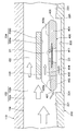
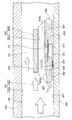
- FIG. 17 is an enlarged diagram schematically showing a main part of the configuration shown in FIG.
- the third protruding portion 304 of the circuit board 300 is arranged so that one surface 304a and the other surface 304b are arranged in the sub-passage 134 along the passage direction of the sub-passage 134, which is the flow direction of the gas to be measured.
- the support 401 of the sensor assembly 400 is arranged at a position facing the one surface 304a of the third protrusion 304.
- the support 401 of the sensor assembly 400 is arranged in the sub-passage 134 so as to face the third protrusion 304 of the circuit board 300 and to overlap in the direction intersecting the flow direction of the gas to be measured.
- the direction in which the third protrusion 304 of the circuit board 300 and the support 401 of the sensor assembly 400 overlap may be referred to as a stacking direction.
- the support 401 of the sensor assembly 400 is arranged such that the concave groove 404 is along the passage direction of the sub-passage 134.
- the third protrusion 304 of the circuit board 300 and the sensor assembly 400 correspond to the substrate and the support in the claims, respectively.
- the concave groove 404 of the support 401 is covered by the third protrusion 304 of the circuit board 300, and the first passage portion having a closed cross section through which the gas to be measured can flow between the support 401 and the circuit board 300.
- D1 is formed.
- the first passage portion D1 has a first gap between the bottom surfaces 405a and 405b of the concave groove 404 and one surface 304a of the third protrusion 304 of the circuit board 300.
- the flow rate sensor 411 exposed in the concave groove 404 of the support 401 is arranged so as to face one surface 304a of the third protrusion 304 of the circuit board 300.
- the flow rate sensor 411 measures the flow rate of the gas to be measured passing between the support 401 and the third protrusion 304 of the circuit board 300.
- the third protrusion 304 of the circuit board 300 is arranged in the sub-passage 134 at a position away from the bottom wall surface 152a of the second sub-passage groove 152.
- a second passage portion D2 having a closed cross section through which the gas to be measured can flow is formed between the third protrusion 304 of the circuit board 300 and the bottom wall surface 152a of the second sub-passage groove 152.
- the second passage portion D2 has a second gap through which the gas to be measured passes between the third protrusion 304 of the circuit board 300 and the bottom wall surface 152a of the second sub-passage groove 152.
- the support 401 is arranged at a position away from the cover 200 in the sub-passage 134.
- a third passage portion D3 having a closed cross section through which the gas to be measured can flow is formed between the support 401 and the cover 200 in the sub-passage 134.
- the third passage portion D3 has a third gap between the support 401 and the cover 200.
- the first passage portion D1 having a first gap through which the gas to be measured passes between the third protrusion 304 of the circuit board 300 and the concave groove 404 of the support 401, and the circuit.
- the second passage portion D2 having a second gap through which the gas to be measured passes between the third protrusion 304 of the substrate 300 and the bottom wall surface 152a of the second sub-passage groove 152, the back surface 402 of the support 401, and the cover.
- a third passage portion D3 having a third gap through which the gas to be measured passes is formed between the 200 and the passage portion D3.
- the first passage portion D1 to the third passage portion D3 are arranged side by side in the sub-passage 134 in the stacking direction in which the third protrusion 304 and the support 401 face each other. That is, the sub-passage 134 has a configuration in which the flow sensor 411 is provided in the middle of the passage and is divided into three passage portions D1 to D3 in the stacking direction.
- the third protrusion 304 and the support 401 of the circuit board 300 cooperate with each other to contact both the bottom wall surface 152a and the cover 200 of the second sub-passage groove 152 constituting the passage wall surface of the sub-passage 134. Instead, it is arranged in a state of floating in the air in the sub-passage 134, that is, at an intermediate position in the groove depth direction of the second sub-passage groove 152.
- the flow rate sensor 411 faces only the third protrusion 304 of the circuit board 300, and is arranged at a position not facing the passage wall surface of the sub-passage 134 and the cover 200.
- the support 401 has a first side surface 407 and a second side surface 408 facing each other in the sub-passage 134 in the flow direction of the gas to be measured.
- the first side surface 407 faces the sub-passage 134 toward the upstream side in the flow direction of the gas to be measured, which is on the sub-passage inlet 131 side.
- the second side surface 408 faces the downstream side in the flow direction of the gas to be measured, which is on the side of the second outlet 133 in the sub-passage 134.
- the first side surface 407 and the second side surface 408 are formed in the sub-passage 134 so as to extend in the X-axis direction between the pair of side wall surfaces 152b of the second sub-passage groove 152 facing each other.
- the support 401 is arranged at a position where the first side surface 407 is exposed in the sub-passage 134 when the support 401 is viewed from the upstream side in the flow direction of the gas to be measured through the sub-passage 134.
- the first side surface 407 constitutes a dynamic pressure passive portion that receives the dynamic pressure of the gas to be measured that has flowed through the sub-passage 134.
- the first side surface 407 collides a part of the measured gas flowing from the sub-passage inlet 131 side toward the second outlet 133 side in the sub-passage 134 to passively pass the dynamic pressure of the measured gas, and the measured gas.
- the gas to be measured can be taken into the third passage portion D3 by deflecting the flow of the gas.
- the first side surface 407 is an inclined surface inclined with respect to the flow direction of the gas to be measured.
- the first side surface 407 gradually inclines along the stacking direction from the 1st passage portion D1 side toward the 3rd passage portion D3 side as it shifts in the sub-passage 134 in the flow direction of the gas to be measured. ing. That is, the first side surface 407 is the front surface of the support 401 along the gradually laminating direction as it moves from one end of the tip 401B in the width direction (Z-axis direction) toward the other along the width direction. It is tilted so as to move from the 403 side to the back 402 side. Due to the inclination of the first side surface 407, the gas to be measured that has passively passed the dynamic pressure can be positively guided in the direction toward the third passage portion D3.
- the support 401 is arranged at a position where the second side surface 408 is exposed in the sub-passage 134 when the support 401 is viewed from the downstream side in the flow direction of the gas to be measured through the sub-passage 134.
- the second side surface 408 is an inclined surface inclined with respect to the flow direction of the gas to be measured.
- the second side surface 408 gradually shifts from the end on the other side in the width direction (Z-axis direction) of the tip portion 401B toward one side along the width direction from the front 403 side to the back 402 side along the stacking direction. It is tilted to move to.
- the second side surface 408 is a subject that flows in the opposite direction when the gas to be measured flows in the sub-passage 134 in the opposite direction from the second outlet 133 side toward the sub-passage inlet 131 side due to pulsation in the main passage or the like. A part of the measured gas is made to collide, the dynamic pressure of the measured gas is passive, the flow of the measured gas is deflected, and the measured gas can be taken into the third passage portion D3.
- a recess 202 is formed in a region portion facing the tip portion 401B of the support 401.
- the facing region portion facing the support 401 is recessed in the stacking direction with respect to the periphery of the facing region portion, that is, the region portions upstream and downstream of the facing region portion. Is formed.
- the recess 202 is slightly larger in the width direction than the tip portion 401B of the support 401, and is provided so as to extend between the pair of side wall surfaces 152b of the second sub-passage groove 152.
- the third passage portion D3 is formed by a gap between the recess 202 and the support 401.
- the cover 200 has a recess 202, an inner wall surface 201 continuous via a step 204 arranged on the sub-passage inlet 131 side (upstream side in the flow direction of the gas to be measured) of the sub-passage 134, and a second outlet of the sub-passage 134. It has an inner wall surface 203 continuous with a step 205 on the 133 side (downstream side in the flow direction of the gas to be measured).
- the inner wall surfaces 201 and 203 extend in parallel with the bottom wall surface 152a of the second sub-passage groove 152 along the flow direction of the gas to be measured, and the recess 202 is recessed one step from the inner wall surfaces 201 and 203 to support it. It is formed so as to extend parallel to the back surface 402 of the body 401.
- the first side surface 407 of the support 401 is arranged at a position facing the flow direction of the measured gas, and the measured gas flowing through the sub-passage 134 It constitutes a dynamic pressure passive part that receives dynamic pressure. Therefore, a part of the gas to be measured flowing in the sub-passage 134 is made to collide with the first side surface 407, the dynamic pressure of the gas to be measured is passive, and the flow of the gas to be measured is deflected and taken into the third passage portion D3. be able to. Therefore, it is possible to suppress the invasion of pollutants such as dust and water droplets contained in the gas to be measured into the second passage portion D2.
- the inner wall surface 223 is in a direction away from the bottom wall surface 152a of the second sub-passage groove 152 as it moves downstream along the flow direction of the gas to be measured, that is, from the first passage portion D1 side to the third passage. It is inclined so as to move to the portion D3 side.
Landscapes
- Physics & Mathematics (AREA)
- Fluid Mechanics (AREA)
- General Physics & Mathematics (AREA)
- Measuring Volume Flow (AREA)
Abstract
本発明の課題は。耐汚損性を向上させ、被計測気体の流量を正確に測定することができる流量測定装置を得ることである。 本発明の流量測定装置(20)は、副通路(134)内において被計測気体(2)の流れ方向に沿って配置される基板(304)と、基板の一方面(304a)に対向して配置される支持体(401)と、支持体に支持されて基板の一方面に対向し支持体と基板との間を通過する被計測気体の流量を計測する流量センサ(411)とを備える。そして、副通路は、支持体と基板の一方面との間に第1通路部D1と、基板の他方面とこれに対向する副通路の通路壁面との間に第2通路部D2と、支持体とこれに対向する副通路の通路壁面との間に第3通路部D3とを有している。そして、支持体は、副通路内において被計測気体の流れ方向に向かって対向する第1側面(407)を有することを特徴とする。
Description
本発明は、例えば内燃機関の吸入空気の流量を測定する流量測定装置に関する。
流量測定装置の例として特許文献1の技術が開示されている。
特許文献1の流量測定装置は、支持体に搭載された流量検出素子が副通路内で通路壁面に対向して配置され、支持体によって副通路内の流路が、流量測定素子の計測面が配置される流路d1と、計測面が配置されない流路d2とに分流された構造を有している。
しかしながら、被計測気体に水滴や油分等の液状の汚損物が混ざって副通路内に侵入してきた場合や、結露などで通路壁面に付着した液状の汚損物が通路壁面を滴ってきた場合に、流路d1にそのまま流れ込み、流量測定素子に付着するおそれがある。流量測定素子は、液状の汚損物が付着すると、被計測気体の流量の測定精度に影響を与えるおそれがある。
本発明の目的は、耐汚損性を向上させ、被計測気体の流量を正確に測定することができる流量測定装置を提供することを目的とする。
本発明の目的は、耐汚損性を向上させ、被計測気体の流量を正確に測定することができる流量測定装置を提供することを目的とする。
上記課題を解決する本発明の流量測定装置は、主通路を流れる被計測気体の一部を取り込む副通路を備える流量測定装置であって、前記副通路内において前記被計測気体の流れ方向に沿って配置される基板と、前記副通路内において前記基板の一方面に対向して前記被計測気体の流れ方向に交差する方向に重ねて配置される支持体と、該支持体に支持されて前記基板の一方面に対向し前記支持体と前記基板との間を通過する前記被計測気体の流量を計測する流量センサと、を備え、前記副通路は、前記支持体と前記基板の一方面との間に前記被計測気体が通過する第1の空隙を有する第1通路部と、前記基板の他方面と該基板の他方面に対向する前記副通路の通路壁面との間に前記被計測気体が通過する第2の空隙を有する第2通路部と、前記支持体と、該支持体に対向する前記副通路の通路壁面との間に前記被計測気体が通過する第3の空隙を有する第3通路部と、を有し、前記支持体は、前記副通路内において前記被計測気体の流れ方向に向かって対向する側面を有することを特徴とする。
本発明によれば、耐汚損性を向上させ、被計測気体の流量を正確に測定することができる流量測定装置を得ることができる。本発明に関連する更なる特徴は、本明細書の記述、添付図面から明らかになるものである。また、上記した以外の、課題、構成及び効果は、以下の実施形態の説明により明らかにされる。
以下に説明する、発明を実施するための形態(以下、実施例)は、実際の製品として要望されている種々の課題を解決しており、特に車両の吸入空気の物理量を検出する検出装置として使用するために望ましい色々な課題を解決し、種々の効果を奏している。下記実施例が解決している色々な課題の内の一つが、上述した発明が解決しようとする課題の欄に記載した内容であり、また下記実施例が奏する種々の効果のうちの1つが、発明の効果の欄に記載された効果である。下記実施例が解決している色々な課題について、さらに下記実施例により奏される種々の効果について、下記実施例の説明の中で述べる。従って、下記実施例の中で述べる、実施例が解決している課題や効果は、発明が解決しようとする課題の欄や発明の効果の欄の内容以外の内容についても記載されている。
以下の実施例で、同一の参照符号は、図番が異なっていても同一の構成を示しており、同じ作用効果を成す。既に説明済みの構成について、図に参照符号のみを付し、説明を省略する場合がある。
図1は、電子燃料噴射方式の内燃機関制御システム1に、本実施形態に係る物理量検出装置を使用した一実施例を示す、システム図である。エンジンシリンダ11とエンジンピストン12を備える内燃機関10の動作に基づき、吸入空気が被計測気体2としてエアクリーナ21から吸入され、主通路22である例えば吸気ボディと、スロットルボディ23と、吸気マニホールド24を介してエンジンシリンダ11の燃焼室に導かれる。燃焼室に導かれる吸入空気である被計測気体2の物理量は、物理量検出装置20で検出され、その検出された物理量に基づいて燃料噴射弁14より燃料が供給され、被計測気体2と共に混合気の状態で燃焼室に導かれる。なお、本実施例では、燃料噴射弁14は内燃機関の吸気ポートに設けられ、吸気ポートに噴射された燃料が被計測気体2と共に混合気を成形し、吸気弁15を介して燃焼室に導かれ、燃焼して機械エネルギを発生する。
燃焼室に導かれた燃料および空気は、燃料と空気の混合状態を成しており、点火プラグ13の火花着火により、爆発的に燃焼し、機械エネルギを発生する。燃焼後の気体は排気弁16から排気管に導かれ、排気ガス3として排気管から車外に排出される。前記燃焼室に導かれる吸入空気である被計測気体2の流量は、アクセルペダルの操作に基づいてその開度が変化するスロットルバルブ25により制御される。前記燃焼室に導かれる吸入空気の流量に基づいて燃料供給量が制御され、運転者はスロットルバルブ25の開度を制御して前記燃焼室に導かれる吸入空気の流量を制御することにより、内燃機関が発生する機械エネルギを制御することができる。
エアクリーナ21から取り込まれ主通路22を流れる吸入空気である被計測気体2の流量、温度、湿度、圧力などの物理量が物理量検出装置20により検出され、物理量検出装置20から吸入空気の物理量を表す電気信号が制御装置4に入力される。また、スロットルバルブ25の開度を計測するスロットル角度センサ26の出力が制御装置4に入力され、さらに内燃機関のエンジンピストン12や吸気弁15や排気弁16の位置や状態、さらに内燃機関の回転速度を計測するために、回転角度センサ17の出力が、制御装置4に入力される。排気ガス3の状態から燃料量と空気量との混合比の状態を計測するために、酸素センサ28の出力が制御装置4に入力される。
制御装置4は、物理量検出装置20の出力である吸入空気の物理量と、回転角度センサ17の出力に基づき計測された内燃機関の回転速度とに基づいて、燃料噴射量や点火時期を演算する。これら演算結果に基づいて、燃料噴射弁14から供給される燃料量、また点火プラグ13により点火される点火時期が制御される。燃料供給量や点火時期は、実際にはさらに物理量検出装置20で検出される温度やスロットル角度の変化状態、エンジン回転速度の変化状態、酸素センサ28で計測された空燃比の状態に基づいて、きめ細かく制御されている。制御装置4は、さらに内燃機関のアイドル運転状態において、スロットルバルブ25をバイパスする空気量をアイドルエアコントロールバルブ27により制御し、アイドル運転状態での内燃機関の回転速度を制御する。
内燃機関の主要な制御量である燃料供給量や点火時期はいずれも物理量検出装置20の出力を主パラメータとして演算される。従って、物理量検出装置20の検出精度の向上や、経時変化の抑制、信頼性の向上が、車両の制御精度の向上や信頼性の確保に関して重要である。
特に近年、車両の省燃費に関する要望が非常に高く、また排気ガス浄化に関する要望が非常に高い。これらの要望に応えるには、物理量検出装置20により検出される吸入空気の物理量の検出精度の向上が極めて重要である。また、物理量検出装置20が高い信頼性を維持していることも大切である。
物理量検出装置20が搭載される車両は、温度や湿度の変化が大きい環境で使用される。物理量検出装置20は、その使用環境における温度や湿度の変化への対応や、塵埃や汚染物質などへの対応も、考慮されていることが望ましい。
また、物理量検出装置20は、内燃機関からの発熱の影響を受ける吸気管に装着される。このため、内燃機関の発熱が吸気管を介して物理量検出装置20に伝わる。物理量検出装置20は、被計測気体と熱伝達を行うことにより被計測気体の流量を検出するので、外部からの熱の影響をできるだけ抑制することが重要である。
車に搭載される物理量検出装置20は、以下で説明するように、単に発明が解決しようとする課題の欄に記載された課題を解決し、発明の効果の欄に記載された効果を奏するのみでなく、以下で説明するように、上述した色々な課題を十分に考慮し、製品として求められている色々な課題を解決し、色々な効果を奏している。物理量検出装置20が解決する具体的な課題や奏する具体的な効果は、以下の実施例の記載の中で説明する。
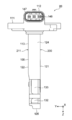
<第1実施形態> 図2から図7は、物理量検出装置の外観を示す図である。以下の説明では、主通路22の中心軸22Aに沿って被計測気体2が流れるものとする。本実施形態の物理量検出装置20は、被計測気体2の物理量の一つである流量を計測する流量計測装置としての機能も含むものである。
物理量検出装置20は、主通路22の通路壁に設けられた取り付け孔から主通路22の内部に挿入して主通路22に固定された状態で使用される。物理量検出装置20は、被計測気体が流れる主通路22に配置される筐体を備えている。物理量検出装置20の筐体は、ハウジング100と、ハウジング100に取り付けられるカバー200を有している。
ハウジング100は、例えば合成樹脂製材料を射出成形することによって構成されている。
ハウジング100は、例えば合成樹脂製材料を射出成形することによって構成されている。
カバー200は、例えば金属材料や合成樹脂製材料からなる板状部材によって構成されており、本実施形態では、アルミニウム合金あるいは合成樹脂製材料の射出成形品によって構成されている。カバー200は、図2に示すように、ハウジング100の正面を全面的に覆う大きさを有している。
ハウジング100は、物理量検出装置20を主通路22である吸気ボディに固定するためのフランジ111と、フランジ111から突出して外部機器との電気的な接続を行うために吸気ボディから外部に露出するコネクタ112と、フランジ111から主通路22の中心に向かって突出するように延びる計測部113を有している。
計測部113は、主通路22に設けられた取り付け孔から内部に挿入され、物理量検出装置20のフランジ111が主通路22に当接され、ねじで主通路22に固定される。
計測部113は、フランジ111から真っ直ぐ延びる薄くて長い形状を成し、幅広な正面121と背面122、及び幅狭な一対の側面123、124を有している。計測部113は、物理量検出装置20を主通路22に取り付けた状態で、主通路22の内壁から主通路22の通路中心に向かって突出する。そして、正面121と背面122が主通路22の中心軸22Aに沿って平行に配置され、計測部113の幅狭な側面123、124のうち計測部113の長手方向一方側の側面123が主通路22の上流側(エアクリーナ側)に対向配置され、計測部113の短手方向他方側の側面124が主通路22の下流側(エンジン側)に対向配置される。
本実施形態では、物理量検出装置20を主通路22に取り付けた状態で、計測部113の基端部が上側に配置され、計測部113の先端部が下側に配置される。そして計測部113の先端部に下面125を有する。ただし、物理量検出装置20が使用される姿勢状態は、本実施形態に限定されるものではなく、種々の姿勢状態とすることができ、例えば計測部113の基端部と先端部とが同じ高さとなるように水平に取り付けられる姿勢状態であってもよい。
以下の説明では、フランジ111から計測部113が延びる方向である計測部113の長手方向の軸をZ軸、計測部113の副通路入口131から第1出口132に向かって延びる方向である計測部113の短手方向の軸をX軸、計測部113の正面121から背面122に向かう方向である計測部113の厚さ方向の軸をY軸と称する場合がある。
計測部113は、X軸方向一方側の側面123に副通路入口131が設けられ、X軸方向他方側の側面124に第1出口132及び第2出口133が設けられている。副通路入口131と第1出口132及び第2出口133は、フランジ111から主通路22の中心方向に向かってZ軸方向に延びる計測部113の先端部に設けられている。したがって、主通路22を流れる被計測気体2のうち、主通路22の内壁面から離れた中央部に近い部分の被計測気体2を副通路134に取り込むことができる。このため、物理量検出装置20は、主通路22の内壁面から離れた部分の被計測気体2の流量を測定することができ、熱などの影響による計測精度の低下を抑制できる。
計測部113は、計測部113が主通路22の外壁から中央に向かうZ軸に沿って長く伸びる形状を成しているが、側面123、124のY軸方向の幅は、狭い形状を成している。これにより、物理量検出装置20は、被計測気体2に対しては流体抵抗を小さい値に抑えることができる。
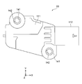
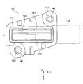
計測部113は、主通路22に設けられた取り付け孔から内部に挿入され、フランジ111が主通路22に当接され、ねじで主通路22に固定される。フランジ111は、所定の板厚からなる平面視略矩形状を有しており、図6及び図7に示すように、対角線上の角部には固定穴部141が対をなして設けられている。固定穴部141は、フランジ111を貫通する貫通孔142を有している。フランジ111は、固定穴部141の貫通孔142に、不図示の固定ネジが挿通されて主通路22のネジ穴に螺入されることにより主通路22に固定される。
コネクタ112は、図5に示すように、その内部に3本の外部端子147と補正用端子148が設けられている。外部端子147は、物理量検出装置20の計測結果である流量や温度などの物理量を出力するための端子および物理量検出装置20が動作するための直流電力を供給するための電源端子である。補正用端子148は、生産された物理量検出装置20の計測を行い、それぞれの物理量検出装置20に関する補正値を求めて、物理量検出装置20内部のメモリに補正値を記憶するのに使用する端子であり、その後の物理量検出装置20の計測動作では上述のメモリに記憶された補正値を表す補正データが使用され、この補正用端子148は使用されない。
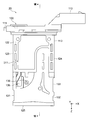
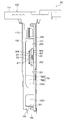
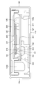
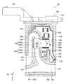
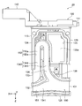
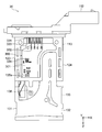
図8は、図4のVIII-VIII線断面図、図9は、図2のIX-IX線断面図、図10は、図2に示す物理量検出装置のカバーを取り外した状態を示す図、図11は、図10に示す物理量検出装置から回路基板を取り外した状態を示す図、図12は、図4に示す物理量検出装置の開口窓を封止する前の状態を示す図である。
ハウジング100の計測部113には、流量検出素子である流量センサ411と、吸気温度センサ321と、湿度センサ322が設けられている。流量センサ411は、主通路を流れる被計測気体2の流量を検出する。流量センサ411は、ダイヤフラム構造を有しており、副通路134の通路途中に配置されている。吸気温度センサ321は、側面123の副通路入口131近傍に一端が開口し、他端が計測部113の正面121と背面の両方に開口する温度検出通路136の通路途中に配置されている。吸気温度センサ321は、主通路を流れる被計測気体2の温度を検出する。湿度センサ322は、計測部113の湿度計測室137に配置されている。湿度センサ322は、計測部113の背面に開口する窓部138から湿度計測室137に取り入れられた被計測気体の湿度を計測する。
計測部113には、副通路134を形成するための副通路溝150と、回路基板300を収容するための回路室135が設けられている。回路室135と副通路溝150は、計測部113の正面121に凹設されており、計測部113の正面121にカバー200を取り付けることによって覆われて蓋がされる構造となっている。
回路室135は、主通路22において被計測気体2の流れ方向上流側の位置となるX軸方向一方側(側面123側)の領域に設けられている。回路室135には、計測部113をY軸方向に貫通する開口窓135aが設けられている。開口窓135aは、計測部113の背面に開口しており、回路基板300を計測部113に装着した際に、回路基板300の背面を部分的に露出させることができるようになっている。開口窓135aは、回路基板300の背面のうち、少なくともボンディングパッド332を露出させ、計測部113の接続端子331との間を線材333で接続する作業ができるようになっている。開口窓135aは、ボンディングパッド332と接続端子331との間が線材333で接続された後に、エポキシ樹脂などの硬化剤が充填されて完全に閉塞される。
副通路溝150は、回路室135よりも計測部113のZ軸方向先端側(下面125側)の領域と、回路室135よりも主通路22における被計測気体2の流れ方向下流側の位置となるX軸方向他方側(側面124側)の領域に亘って設けられている。
副通路溝150は、計測部113の正面121を覆うカバー200との協働によって副通路134を形成する。副通路溝150は、第1副通路溝151と、第1副通路溝151の途中で分岐する第2副通路溝152とを有している。第1副通路溝151は、計測部113の一方側の側面123に開口する副通路入口131と、計測部113の他方側の側面124に開口する第1出口132との間に亘って、計測部113のX軸方向に沿って延在するように形成されている。第1副通路溝151は、主通路22内を流れる被計測気体2を副通路入口131から取り込み、その取り込んだ被計測気体2を第1出口132から主通路22に戻す第1副通路1331をカバー200との協働により形成する。第1副通路1331は、副通路入口131から主通路22内における被計測気体2の流れ方向に沿って延在し、第1出口132までつながる流路を有する。
第2副通路溝152は、第1副通路溝151の途中位置で分岐して計測部113の基端部側(フランジ側)に向かって屈曲され、計測部113のZ軸方向に沿って延在する。そして、計測部113の基端部で計測部113のX軸方向他方側(側面124側)に向かって折れ曲がり、計測部113の先端部に向かってUターンし、再び計測部113のZ軸方向に沿って延在する。そして、第1出口132の手前で計測部113のX軸方向他方側(側面124側)に向かって屈曲され、計測部113の側面124に開口する第2出口133に連続するように設けられている。第2出口133は、主通路22における被計測気体2の流れ方向下流側に向かって対向配置される。第2出口133は、第1出口132と比較して若干大きい開口面積を有しており、第1出口132よりも計測部113の長手方向基端部側に隣接した位置に形成されている。
第2副通路溝152は、第1副通路1331から分岐されて流れ込んだ被計測気体2を通過させて第2出口133から主通路22に戻す第2副通路1332をカバー200との協働により形成する。第2副通路1332は、計測部113のZ軸方向に沿って往復する流路を有する。つまり、第2副通路1332は、第1副通路1331の途中で分岐して、計測部113の基端部側(第1副通路1331から離れる方向)に向かって延在する往通路部1333と、計測部113の基端部側(往通路部1333の端部)で折り返されてUターンし、計測部113の先端部側(第1副通路1331に接近する方向)に向かって延在する復通路部1334を有している。復通路部1334は、副通路入口131よりも主通路22内における被計測気体2の流れ方向下流側の位置において被計測気体2の流れ方向下流側に向かって開口する第2出口133につながる流路を有する。
第2副通路1332は、往通路部1333の途中位置に流量センサ(流量検出部)411が配置されている。第2副通路1332は、計測部113の長手方向に沿って延在して往復するように通路が形成されているので、通路長さをより長く確保することができ、主通路内に脈動が生じた場合に、流量センサ411への影響を小さくすることができる。流量センサ411は、センサアセンブリ400に設けられており、センサアセンブリ400は、回路基板300に実装されている。
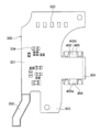
図13は、基板アセンブリの表側を示す図、図14は、基板アセンブリの裏側を示す図である。
回路基板300は、表側の実装面に、センサアセンブリ400、圧力センサ320、吸気温度センサ321、湿度センサ322等の回路部品が実装されており、裏面側の実装面には、チップ抵抗やチップコンデンサなどの回路部品334とボンディングパッド332が設けられている。回路基板300は、平面視で略長方形状を有しており、図10に示すように、回路基板300の長手方向が計測部113の基端部から先端部に向かって延在し、回路基板300の短手方向が計測部113の側面123から側面124に向かって延在するように計測部113内に配置される。
回路基板300は、表側の実装面に、センサアセンブリ400、圧力センサ320、吸気温度センサ321、湿度センサ322等の回路部品が実装されており、裏面側の実装面には、チップ抵抗やチップコンデンサなどの回路部品334とボンディングパッド332が設けられている。回路基板300は、平面視で略長方形状を有しており、図10に示すように、回路基板300の長手方向が計測部113の基端部から先端部に向かって延在し、回路基板300の短手方向が計測部113の側面123から側面124に向かって延在するように計測部113内に配置される。
回路基板300は、回路室135内に配置される基板本体301を有しており、温度検出通路136に配置される第1突出部302と、湿度計測室137に配置される第2突出部303と、第2副通路1332の往通路部1333に配置される第3突出部304とがそれぞれ基板本体301から面一に延びるように設けられている。第1突出部302の先端部には、吸気温度センサ321が実装され、第2突出部303には湿度センサ322が実装されている。第3突出部304は、第2副通路1332の往通路部1333においてセンサアセンブリ400と対向して配置される。回路基板300の第3突出部304は、センサアセンブリ400の凹溝404の開放部分を閉塞して第1通路部D1を形成する。また、回路基板300の第3突出部304は、第2副通路溝152の底壁面152aとの間に第2通路部D2を形成する。
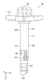
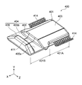
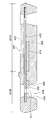
図15は、第1実施形態におけるセンサアセンブリの斜視図、図16は、図9に示す構成からセンサアセンブリのみを拡大した断面図である。
センサアセンブリ400は、流量センサ411とLSI412とリードフレーム413を樹脂でモールドした樹脂パッケージの構造を有している。流量センサ411とLSI412は、リードフレーム413に実装されている。センサアセンブリ400は、流量センサ411のダイヤフラムが露出するように流量センサ411を樹脂で封止することによって形成されている。センサアセンブリ400は、モールド樹脂によって形成された所定の板厚を有する平板形状の支持体401を有している。センサアセンブリ400は、支持体401の基端部401Aが回路室135内に配置され、支持体401の先端部401Bが第2副通路溝152に突出して配置される。センサアセンブリ400は、固定部によって、回路基板300に電気的に接続され、かつ、機械的に固定される。
支持体401の基端部401Aには、複数本の接続端子414が設けられている。複数の接続端子414は、支持体401の基端部401Aの幅方向両端部から支持体401の幅方向(図15のZ軸)に沿って互いに離反する方向に向かって突出して設けられており、各接続端子414の先端は、基端部401Aの厚さ方向に折曲されて基端部401Aの正面403よりも厚さ方向(図15のY軸)に突出した位置に配置されている。
支持体401の先端部401Bは、第2副通路1332の往通路部1333内において回路基板300の第3突出部304に対向して配置される。支持体401の先端部401Bには、凹溝404が形成されている。凹溝404は、支持体401の先端部401Bの正面403において、支持体401の先端部401Bの幅方向(図15のZ軸)に亘って延在するように形成されており、延在する方向の中間位置に流量センサ411が露出して配置されている。
凹溝404は、流量センサ411から互いに離反する方向に延びる底面405a、405bと、互いに対向する一対の壁面406とを有する。底面405aは、支持体401の幅方向一方側の端部から流量センサ411に接近する方向に移行するにしたがって溝深さが漸次浅くなるように傾斜して形成されている。一方、底面405bは、支持体401の幅方向他方側の端部と流量センサ411と間において一定の溝深さを有するように平坦に形成されている。一対の壁面406は、支持体401の幅方向両端部から流量センサ411に接近する方向に移行するにしたがって漸次互いに接近する絞り形状となっている。
センサアセンブリ400は、流量センサ411を封止する樹脂で絞り形状を形成することで、絞りと計測部との位置関係を精度よく構成でき、計測精度が向上するため好ましい。また、計測面と垂直な方向で絞る場合と比べて、計測面と並行な方向で絞ることにより、汚損物を含んだ空気が計測面にガイドされる量が低減されるため、耐汚損性にも優れる。なお、LSI412と流量センサ411を一体化した構成や、LSI412を回路基板300に固定する構成としてもよい。また、センサアセンブリ400は、金属端子を樹脂で封止した樹脂成型体(センサ支持体)に流量センサ411を実装した構造であってもよい。センサアセンブリ400は、流量センサ411と流量センサ411を支持する部材を少なくとも備えている支持体である。
センサアセンブリ400は、第2副通路1332の往通路部1333に沿って凹溝404が延在するように配置される。センサアセンブリ400は、流量センサ411が回路基板300の一部である第3突出部304と対向するように配置される。センサアセンブリ400は、支持体401の通路壁314と回路基板300の第3突出部304との間に第1通路部D1が形成されている。第1通路部D1には、第2副通路1332を流れる被計測気体が通過し、流量センサ411によって被計測気体の流量が検出される。
センサアセンブリ400は、接続端子414を回路基板300にはんだ付けすることによって回路基板300に固定される。つまり、はんだ付けされた部分が、センサアセンブリ400を回路基板300に電気的に接続し、かつ、機械的に固定する固定部を構成する。ただし、センサアセンブリ400を回路基板300に固定する固定方法としては、はんだ付けに限定されるものではない。例えば、複数の接続端子をプレスフィット端子によって構成し、これらのプレスフィット端子を回路基板300に穿設されたスルーホールに挿入することによって接続するプレスフィットや、銀ペーストなどの導電性接着剤を塗布して複数の接続端子414を回路基板300の接続パッドに接着して固定する方法を採用してもよい。
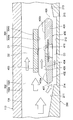
図17は、図8に示す構成の要部を拡大して模式的に示す図である。
回路基板300の第3突出部304は、その一方面304aと他方面304bが副通路134内において被計測気体の流れ方向である副通路134の通路方向に沿うように配置されている。そして、第3突出部304の一方面304aに対向する位置にセンサアセンブリ400の支持体401が配置されている。
回路基板300の第3突出部304は、その一方面304aと他方面304bが副通路134内において被計測気体の流れ方向である副通路134の通路方向に沿うように配置されている。そして、第3突出部304の一方面304aに対向する位置にセンサアセンブリ400の支持体401が配置されている。
センサアセンブリ400の支持体401は、副通路134内において回路基板300の第3突出部304に対向して被計測気体の流れ方向に交差する方向に重ねて配置されている。以下、回路基板300の第3突出部304とセンサアセンブリ400の支持体401とが重なる方向を積層方向と称して説明する場合がある。センサアセンブリ400の支持体401は、凹溝404が副通路134の通路方向に沿うように配置されている。回路基板300の第3突出部304と、センサアセンブリ400が、それぞれ特許請求の範囲における基板と支持体に相当する。
支持体401の凹溝404は、回路基板300の第3突出部304によって覆われており、支持体401と回路基板300との間に被計測気体が流通可能な閉断面を有する第1通路部D1が形成されている。第1通路部D1は、凹溝404の底面405a、405bと回路基板300の第3突出部304の一方面304aとの間に第1の空隙を有している。支持体401の凹溝404に露出する流量センサ411は、回路基板300の第3突出部304の一方面304aに対向して配置されている。流量センサ411は、支持体401と回路基板300の第3突出部304との間を通過する被計測気体の流量を計測する。
そして、回路基板300の第3突出部304は、副通路134内において第2副通路溝152の底壁面152aから離れた位置に配置されている。回路基板300の第3突出部304と第2副通路溝152の底壁面152aとの間には、被計測気体が流通可能な閉断面を有する第2通路部D2が形成されている。第2通路部D2は、回路基板300の第3突出部304と第2副通路溝152の底壁面152aとの間に被計測気体が通過する第2の空隙を有している。
そして、支持体401は、副通路134内においてカバー200から離れた位置に配置されている。支持体401とカバー200との間には、副通路134内を被計測気体が流通可能な閉断面を有する第3通路部D3が形成されている。第3通路部D3は、支持体401とカバー200との間に第3の空隙を有している。
つまり、副通路134内には、回路基板300の第3突出部304と支持体401の凹溝404との間に被計測気体が通過する第1の空隙を有する第1通路部D1と、回路基板300の第3突出部304と第2副通路溝152の底壁面152aとの間に被計測気体が通過する第2の空隙を有する第2通路部D2と、支持体401の背面402とカバー200との間に被計測気体が通過する第3の空隙を有する第3通路部D3が形成されている。
第1通路部D1~第3通路部D3は、副通路134内において第3突出部304と支持体401とが対向する積層方向に並んで配置されている。つまり、副通路134は、その通路途中の流量センサ411が設けられている部分において、積層方向に3つの通路部D1~D3に分割された構成を有している。
回路基板300の第3突出部304と支持体401は、互いに協働して副通路134の通路壁面を構成する第2副通路溝152の底壁面152aおよびカバー200のいずれにも接触しておらず、副通路134内において宙に浮いた状態、つまり、第2副通路溝152の溝深さ方向において中間の位置に配置されている。そして、流量センサ411は、回路基板300の第3突出部304のみと対向しており、副通路134の通路壁面およびカバー200とは対向しない位置に配置されている。
そして、支持体401は、副通路134内で被計測気体の流れ方向に向かって対向する第1側面407と第2側面408とを有する。第1側面407は、副通路134内で副通路入口131側となる被計測気体の流れ方向上流側に向かって対向している。第2側面408は、副通路134内で第2出口133側となる被計測気体の流れ方向下流側に向かって対向している。第1側面407と第2側面408は、副通路134内において、第2副通路溝152の互いに対向する一対の側壁面152bの間に亘ってX軸方向に延びるように形成されている。
支持体401は、副通路134を通して被計測気体の流れ方向上流側から支持体401を見た場合に、副通路134内に第1側面407が露出する位置に配置されている。第1側面407は、副通路134を流れてきた被計測気体の動圧を受ける動圧受動部を構成する。第1側面407は、副通路134内を副通路入口131側から第2出口133側に向かって流れる被計測気体の一部を衝突させて、被計測気体の動圧を受動し、被計測気体の流れを偏向させて被計測気体を第3通路部D3に取り込ませることができる。
第1側面407は、被計測気体の流れ方向に対して傾斜した傾斜面となっている。第1側面407は、副通路134内において被計測気体の流れ方向に移行するにしたがって積層方向に沿って漸次第1通路部D1側から第3通路部D3側に向かって移行する向きに傾斜している。つまり、第1側面407は、先端部401Bの幅方向(Z軸方向)一方側の端部から幅方向に沿って他方側に向かって移行するにしたがって漸次積層方向に沿って支持体401の正面403側から背面402側に移行するように傾斜している。この第1側面407の傾斜によって、動圧を受動した被計測気体を、第3通路部D3に向かう方向に積極的に案内することができる。
支持体401は、副通路134を通して被計測気体の流れ方向下流側から支持体401を見た場合に、第2側面408が副通路134内に露出する位置に配置されている。第2側面408は、第1側面407と同様に、被計測気体の流れ方向に対して傾斜した傾斜面となっている。第2側面408は、先端部401Bの幅方向(Z軸方向)他方側の端部から幅方向に沿って一方側に向かって移行するにしたがって漸次積層方向に沿って正面403側から背面402側に移行するように傾斜している。第2側面408は、主通路内の脈動等によって被計測気体が副通路134内を第2出口133側から副通路入口131側に向かって逆方向に流れた場合に、その逆方向に流れる被計測気体の一部を衝突させて、被計測気体の動圧を受動し、被計測気体の流れを偏向させて被計測気体を第3通路部D3に取り込むことができる。
カバー200には、支持体401の先端部401Bと対向する領域部分に凹部202が形成されている。凹部202は、カバー200の内壁面のうち、支持体401に対向する対向領域部分が、対向領域部分の周囲、つまり、対向領域部分よりも上流および下流の領域部分に対して積層方向に陥凹して形成されている。凹部202は、支持体401の先端部401Bよりも若干幅方向に大きく、第2副通路溝152の一対の側壁面152bの間に亘って延在するように設けられている。第3通路部D3は、凹部202と支持体401との間の隙間によって形成されている。
カバー200は、凹部202と、副通路134の副通路入口131側(被計測気体の流れ方向上流側)に配置される段差204を介して連続する内壁面201と、副通路134の第2出口133側(被計測気体の流れ方向下流側)に段差205を介して連続する内壁面203とを有している。内壁面201と203は、被計測気体の流れ方向に沿って第2副通路溝152の底壁面152aと平行に延在しており、凹部202は、内壁面201、203から一段凹んで、支持体401の背面402と平行に延在するように形成されている。
第3通路部D3の入口は、カバー200の段差204と支持体401の第1側面407との協働により、クランク状に曲がった形状となっている。このクランク状に曲がった形状によって、第1側面407で動圧が受動された被計測気体が、第1通路部D1と第3通路部D3に取り込まれる割合を調整することができる。
次に、上記した構成による作用効果について説明する。
本実施形態の物理量検出装置20によれば、副通路134内は、流量を検出する部分において、積層方向に第1通路部D1と、第2通路部D2と、第3通路部D3に分割されており、第1通路部D1には、流量センサ411が配置されている。そして、第1通路部D1の積層方向両側に、第2通路部D2と第3通路部D3が配置されている。したがって、副通路134内に水滴や油分、ダストなどを含む汚損物が侵入してきた場合に、汚損物を第1通路部D1から第3通路部D3の3つの通路部に分散し、第2通路部D2に配置されている流量センサ411に到達する汚損物の到達量を低減することができる。
本実施形態の物理量検出装置20によれば、副通路134内は、流量を検出する部分において、積層方向に第1通路部D1と、第2通路部D2と、第3通路部D3に分割されており、第1通路部D1には、流量センサ411が配置されている。そして、第1通路部D1の積層方向両側に、第2通路部D2と第3通路部D3が配置されている。したがって、副通路134内に水滴や油分、ダストなどを含む汚損物が侵入してきた場合に、汚損物を第1通路部D1から第3通路部D3の3つの通路部に分散し、第2通路部D2に配置されている流量センサ411に到達する汚損物の到達量を低減することができる。
そして、本実施形態の物理量検出装置によれば、回路基板300の第3突出部304と支持体401は、第2副通路溝152の底壁面152aおよびカバー200のいずれにも接触しておらず、第1通路部D1は副通路134内で宙に浮いた位置に配置されている。そして、第1通路部D1に設けられている流量センサ411は、回路基板300の第3突出部304のみと対向しており、副通路134の通路壁面およびカバー200とは対向しない位置に配置されている。したがって、例えば、水滴や油分などの汚損物が副通路134の壁面を伝って移動してきた場合や、結露によって副通路134の壁面に付着した水滴等の汚損物が壁面を伝って移動してきた場合に、第2通路部D2および第3通路部D3に積極的に案内して、第1通路部D1に侵入するのを防止し、汚損物が流量センサ411に付着するのを防ぐことができる。
特に、本実施形態では、計測部113が上下に延在するように物理量検出装置20を主通路22に取り付けた構成を有している。したがって、副通路134内で流量センサ411よりも上方の位置まで吸い込まれた水滴や油分などの汚損物や、流量センサ411よりも上方の位置に発生した結露水などの汚損物が副通路134の通路壁を伝って、流量センサ411の付近まで移動して来る可能性がある。
これに対し、本実施形態では、回路基板300の第3突出部304およびセンサアセンブリ400は、第2副通路溝152の底壁面152aおよびカバー200の内壁面203から離れており、副通路134内で宙に浮いた状態となっている。したがって、例えば汚損物が副通路134の通路壁を伝って上方から垂れてきた場合には、第2通路部D2と、第3通路部D3を通過させ、そのまま下方に落とすことが可能であり、液体の汚損物が、第1通路部D1に入り込んで流量センサ411に付着するのを防ぐことができる。
そして、本実施形態の物理量検出装置20によれば、支持体401の第1側面407が被計測気体の流れ方向に対向する位置に配置されており、副通路134を流れてきた被計測気体の動圧を受ける動圧受動部を構成している。したがって、副通路134内を流れる被計測気体の一部を第1側面407に衝突させて、被計測気体の動圧を受動し、被計測気体の流れを偏向させて第3通路部D3に取り込むことができる。したがって、被計測気体に含まれているダストや水滴などの汚損物が第2通路部D2に侵入するのを抑制することができる。
特に、第1側面407は、被計測気体の流れ方向となる先端部401Bの幅方向(Z軸方向)一方側の端部から幅方向に沿って他方側に向かって移行するにしたがって漸次支持体401の正面403側から背面402側に移行するように傾斜している。この第1側面407の傾斜によって、動圧を受動した被計測気体を、第3通路部D3に向かう方向に積極的に案内することができる。
そして、本実施形態の物理量検出装置20によれば、カバー200には、支持体401の先端部401Bと対向する領域部分に凹部202が形成されており、凹部202と支持体401との間に第3通路部D3が形成されている。カバー200の段差204と支持体401の第1側面407との協働により、第3通路部D3の入口は、クランク状に曲がった形状となっている。このクランク状に曲がった形状によって、第1側面407で動圧が受動された被計測気体を第1通路部D1と第3通路部D3に取り込む割合を、調整することができる。また、第3通路部D3をクランク状に曲がった形状とすることによって、毛細管現象を発生させ、第3通路部D3に汚損物を積極的に取り込み、第3通路部D3を通過させて排出させることができる。
(変形例1) 次に、本実施形態の変形例1について説明する。
図18は、図17に示す構成の変形例を示す図である。
本変形例において特徴的なことは、カバー200の内壁面211、213に傾斜を付けたことである。
図18は、図17に示す構成の変形例を示す図である。
本変形例において特徴的なことは、カバー200の内壁面211、213に傾斜を付けたことである。
カバー200は、凹部202と、凹部202の被計測気体の流れ方向上流側となる副通路入口131側に段差214を介して連続する内壁面(上流領域部分)211と、凹部202の被計測気体の流れ方向下流側となる第2出口133側に段差215を介して連続する内壁面213とを有している。内壁面211は、被計測気体の流れ方向に沿って下流側に移行するにしたがって、第2副通路溝152の底壁面152aから離れる方向、つまり、第3突出部304と支持体401とが対向する積層方向に沿って第1通路部D1側から第3通路部D3側に接近する方向に移行するように傾斜している。そして、内壁面213は、被計測気体の流れ方向に沿って下流側に移行するにしたがって第2副通路溝152の底壁面152aに接近する方向、つまり、第3突出部304と支持体401とが対向する積層方向に沿って第3通路部D3側から第1通路部D1側に移行するように傾斜している。
カバー200の内壁面211は、その傾斜によって、支持体401の第1側面407が受ける動圧を増加させることができ、副通路134内を流れる被計測気体を、より積極的に第3通路部D3に向かって偏向させ、第3通路部D3に取り込ませる被計測気体の流量を増加させることができる。そして、被計測気体に含まれている汚損物を第3通路部D3に導き、第1通路部D1に流れ込む汚損物の量を低減し、第1通路部D1内の流量センサ411の耐汚損性を更に向上させることができる。
カバー200の内壁面212は、脈動により、副通路134内に逆流が発生した場合に、内壁面211と同様に、その傾斜によって副通路134内を流れる被計測気体を、支持体401の第2側面408が受ける動圧を増加させることができ、より積極的に第3通路部D3に向かって偏向させ、第3通路部D3に取り込ませる被計測気体の流量を増加させることができる。そして、被計測気体に含まれている汚損物を第3通路部D3に導き、流量センサ411の耐汚損性を向上させることができる。
(変形例2) 次に、本実施形態の変形例2について説明する。
図19は、図17に示す構成の変形例を示す図である。本変形例において特徴的なことは、カバー200の内壁面221、223に、変形例1とは逆方向の傾斜を付けたことである。
図19は、図17に示す構成の変形例を示す図である。本変形例において特徴的なことは、カバー200の内壁面221、223に、変形例1とは逆方向の傾斜を付けたことである。
カバー200は、凹部202と、凹部202の被計測気体の流れ方向上流側となる副通路入口131側に段差224を介して連続する内壁面(上流領域部分)221と、凹部202の第2出口133側に段差225を介して連続する内壁面223とを有している。内壁面221は、被計測気体の流れ方向に沿って下流側に移行するにしたがって第2副通路溝152の底壁面152aに接近する方向、つまり、第3突出部304と支持体401とが対向する積層方向に沿って第3通路部D3側から第1通路部D1側に移行するように傾斜している。そして、内壁面223は、被計測気体の流れ方向に沿って下流側に移行するにしたがって第2副通路溝152の底壁面152aに離反する方向、つまり、第1通路部D1側から第3通路部D3側に移行するように傾斜している。
カバー200の内壁面221は、その傾斜によって、副通路134内を流れる被計測気体を、第1通路部D1に向かって偏向させ、支持体401の第1側面407が受ける動圧を低減させることができ、第3通路部D3に取り込ませる被計測気体の流量を減少させることができる。これにより、第1通路部D1に流入される被計測気体の流速を向上させ、高精度な流量測定を行うことができる。また、被計測気体の一部を、第3通路部D3に取り込ませることもでき、耐汚損性と流量測定精度の両立を図ることができる。
カバー200の内壁面223は、脈動により、副通路134内に逆流が発生した場合に、内壁面221と同様に、その傾斜によって副通路134内を流れる被計測気体を、第1通路部D1に向かって偏向させ、支持体401の第2側面408が受ける動圧を低減させることができ、第3通路部D3に取り込ませる被計測気体の流量を減少させることができる。これにより、第1通路部D1に流入される被計測気体の流速を向上させ、高精度な流量測定を行うことができる。
(変形例3) 次に、本実施形態の変形例3について説明する。
図20は、図17に示す構成の変形例を示す図である。本変形例において特徴的なことは、カバー200の凹部202を省略した構成としたことである。
図20は、図17に示す構成の変形例を示す図である。本変形例において特徴的なことは、カバー200の凹部202を省略した構成としたことである。
カバー200は、第2副通路溝152の底壁面152aと平行に延在する内壁面231を有している。内壁面231は、被計測気体の流れ方向に沿う平坦な形状を有している。したがって、カバー200の内壁面231と支持体401の背面402との間に形成される第3通路部D3は、第3の空隙を有して直線状に延びる形状となる。
本変形例3は、上述の実施例や他の変形例と同様に、支持体401の第1側面407が被計測気体の流れ方向に対向する位置に配置されており、副通路134を流れてきた被計測気体の動圧を受ける動圧受動部を構成している。したがって、副通路134内を流れる被計測気体の一部を第1側面407に衝突させて、被計測気体の動圧を受動し、被計測気体の流れを偏向させて第3通路部D3に取り込むことができる。したがって、被計測気体に含まれているダストや水滴などの汚損物が第2通路部D2に侵入するのを抑制することができる。
特に、本変形例では、第3通路部D3が直線状に延びる形状を有している。したがって、第3通路部D3に毛細管現象を発生させて、第3通路部D3に汚損物を積極的に取り込み、第3通路部D3を通過させて排出させることができ、流量センサ411の耐汚損性を向上させることができる。
以上、本発明の実施形態について詳述したが、本発明は、前記の実施形態に限定されるものではなく、特許請求の範囲に記載された本発明の精神を逸脱しない範囲で、種々の設計変更を行うことができるものである。例えば、前記した実施の形態は本発明を分かりやすく説明するために詳細に説明したものであり、必ずしも説明した全ての構成を備えるものに限定されるものではない。また、ある実施形態の構成の一部を他の実施形態の構成に置き換えることが可能であり、また、ある実施形態の構成に他の実施形態の構成を加えることも可能である。さらに、各実施形態の構成の一部について、他の構成の追加・削除・置換をすることが可能である。
2・・・被計測気体、20・・・物理量検出装置(流量測定装置)、100・・・ハウジング、131・・・副通路入口、133・・・第2出口、134・・・副通路、200・・・カバー、202・・・凹部、300・・・回路基板、304・・・第3突出部(基板)、400・・・センサアセンブリ、401・・・支持体、404・・・凹溝、407・・・第1側面、408・・・第2側面、411・・・流量センサ、150・・・副通路溝、D1・・・第1通路部、D2・・・第2通路部、D3・・・第3通路部
Claims (6)
- 主通路を流れる被計測気体の一部を取り込む副通路を備える流量測定装置であって、
前記副通路内において前記被計測気体の流れ方向に沿って配置される基板と、
前記副通路内において前記基板の一方面に対向して前記被計測気体の流れ方向に交差する方向に重ねて配置される支持体と、
該支持体に支持されて前記基板の一方面に対向し前記支持体と前記基板との間を通過する前記被計測気体の流量を計測する流量センサと、
を備え、
前記副通路は、前記支持体と前記基板の一方面との間に前記被計測気体が通過する第1の空隙を有する第1通路部と、前記基板の他方面と該基板の他方面に対向する前記副通路の通路壁面との間に前記被計測気体が通過する第2の空隙を有する第2通路部と、前記支持体と、該支持体に対向する前記副通路の通路壁面との間に前記被計測気体が通過する第3の空隙を有する第3通路部と、を有し、
前記支持体は、前記副通路内において前記被計測気体の流れ方向に向かって対向する側面を有することを特徴とする流量測定装置。 - 前記側面は、前記副通路内において前記被計測気体の流れ方向に移行するにしたがって漸次前記第1通路部側から前記第3通路部側に向かって移行する向きに傾斜していることを特徴とする請求項1に記載の流量測定装置。
- 前記副通路の通路壁面は、前記支持体に対向する対向領域部分と、該対向領域部分よりも前記被計測気体の流れ方向上流側に段差を介して連続する上流領域部分とを有しており、前記対向領域部分の方が前記上流領域部分よりも前記支持体から離反した位置に配置されていることを特徴とする請求項1に記載の流量測定装置。
- 前記上流領域部分は、前記被計測気体の流れ方向下流側に移行するにしたがって、前記基板と前記支持体とが対向する方向に沿って前記対向領域部分に接近する方向に移行するように傾斜していることを特徴とする請求項3に記載の流量測定装置。
- 前記上流領域部分は、前記被計測気体の流れ方向下流側に移行するにしたがって、前記基板と前記支持体とが対向する方向に沿って前記対向領域部分から離反する方向に移行するように傾斜していることを特徴とする請求項3に記載の流量測定装置。
- 前記副通路の通路壁面のうち、前記支持体に対向する前記対向領域部分が該対向領域部分の周囲よりも凹んでいることを特徴とする請求項3に記載の流量測定装置。
Priority Applications (4)
| Application Number | Priority Date | Filing Date | Title |
|---|---|---|---|
| JP2022528420A JP7350173B2 (ja) | 2020-06-05 | 2021-01-29 | 流量測定装置 |
| US18/008,027 US20230251120A1 (en) | 2020-06-05 | 2021-01-29 | Flow Rate Measurement Device |
| CN202180037362.6A CN115667856A (zh) | 2020-06-05 | 2021-01-29 | 流量测定装置 |
| DE112021001988.0T DE112021001988T5 (de) | 2020-06-05 | 2021-01-29 | Durchflussraten-messvorrichtung |
Applications Claiming Priority (2)
| Application Number | Priority Date | Filing Date | Title |
|---|---|---|---|
| JP2020098968 | 2020-06-05 | ||
| JP2020-098968 | 2020-06-05 |
Publications (1)
| Publication Number | Publication Date |
|---|---|
| WO2021245976A1 true WO2021245976A1 (ja) | 2021-12-09 |
Family
ID=79281097
Family Applications (1)
| Application Number | Title | Priority Date | Filing Date |
|---|---|---|---|
| PCT/JP2021/003178 Ceased WO2021245976A1 (ja) | 2020-06-05 | 2021-01-29 | 流量測定装置 |
Country Status (5)
| Country | Link |
|---|---|
| US (1) | US20230251120A1 (ja) |
| JP (1) | JP7350173B2 (ja) |
| CN (1) | CN115667856A (ja) |
| DE (1) | DE112021001988T5 (ja) |
| WO (1) | WO2021245976A1 (ja) |
Citations (3)
| Publication number | Priority date | Publication date | Assignee | Title |
|---|---|---|---|---|
| JP2002168669A (ja) * | 2000-12-04 | 2002-06-14 | Ckd Corp | 熱式流量計 |
| WO2019049513A1 (ja) * | 2017-09-05 | 2019-03-14 | 日立オートモティブシステムズ株式会社 | 熱式流量計 |
| WO2020250870A1 (ja) * | 2019-06-13 | 2020-12-17 | 日立オートモティブシステムズ株式会社 | 流量測定装置 |
Family Cites Families (8)
| Publication number | Priority date | Publication date | Assignee | Title |
|---|---|---|---|---|
| US4981035A (en) * | 1989-08-07 | 1991-01-01 | Siemens Automotive L.P. | Dust defelector for silicon mass airflow sensor |
| JP4811695B2 (ja) * | 2000-05-30 | 2011-11-09 | 株式会社デンソー | 流量測定装置 |
| DE10262337B4 (de) * | 2001-11-19 | 2015-04-02 | Denso Corporation | Gerät zum Messen der Durchflussmenge |
| EP3176546B1 (en) * | 2014-07-30 | 2019-02-20 | Hitachi Automotive Systems, Ltd. | Physical-quantity detection device |
| JP6435420B2 (ja) * | 2015-09-30 | 2018-12-05 | 日立オートモティブシステムズ株式会社 | 樹脂成形体およびセンサ装置 |
| JP6690403B2 (ja) * | 2016-05-24 | 2020-04-28 | 株式会社デンソー | 空気流量測定装置 |
| JP6416357B1 (ja) * | 2017-10-05 | 2018-10-31 | 三菱電機株式会社 | 流量測定装置 |
| JP2020034508A (ja) * | 2018-08-31 | 2020-03-05 | 日立オートモティブシステムズ株式会社 | 物理量検出装置 |
-
2021
- 2021-01-29 CN CN202180037362.6A patent/CN115667856A/zh active Pending
- 2021-01-29 JP JP2022528420A patent/JP7350173B2/ja active Active
- 2021-01-29 WO PCT/JP2021/003178 patent/WO2021245976A1/ja not_active Ceased
- 2021-01-29 DE DE112021001988.0T patent/DE112021001988T5/de active Granted
- 2021-01-29 US US18/008,027 patent/US20230251120A1/en not_active Abandoned
Patent Citations (3)
| Publication number | Priority date | Publication date | Assignee | Title |
|---|---|---|---|---|
| JP2002168669A (ja) * | 2000-12-04 | 2002-06-14 | Ckd Corp | 熱式流量計 |
| WO2019049513A1 (ja) * | 2017-09-05 | 2019-03-14 | 日立オートモティブシステムズ株式会社 | 熱式流量計 |
| WO2020250870A1 (ja) * | 2019-06-13 | 2020-12-17 | 日立オートモティブシステムズ株式会社 | 流量測定装置 |
Also Published As
| Publication number | Publication date |
|---|---|
| JP7350173B2 (ja) | 2023-09-25 |
| DE112021001988T5 (de) | 2023-01-12 |
| JPWO2021245976A1 (ja) | 2021-12-09 |
| CN115667856A (zh) | 2023-01-31 |
| US20230251120A1 (en) | 2023-08-10 |
Similar Documents
| Publication | Publication Date | Title |
|---|---|---|
| WO2019049513A1 (ja) | 熱式流量計 | |
| JPWO2019064887A1 (ja) | 物理量検出装置 | |
| JP7074928B2 (ja) | 物理量検出装置 | |
| JP6807465B2 (ja) | 物理量検出装置 | |
| JP6915160B2 (ja) | 物理量検出装置 | |
| JP2020034508A (ja) | 物理量検出装置 | |
| JP7399348B2 (ja) | 流量測定装置 | |
| JP6855590B2 (ja) | 物理量検出装置 | |
| JP2021067510A (ja) | 物理量検出装置 | |
| JP7350173B2 (ja) | 流量測定装置 | |
| JP7265643B2 (ja) | 流量測定装置 | |
| JP7062135B2 (ja) | 物理量検出装置 | |
| JP7049277B2 (ja) | 物理量検出装置 | |
| CN113167620B (zh) | 物理量测定装置 | |
| JP2019066329A (ja) | 物理量検出装置 | |
| JP6884926B2 (ja) | 物理量検出装置 | |
| JP6744501B2 (ja) | 物理量検出装置 | |
| WO2020250870A1 (ja) | 流量測定装置 |
Legal Events
| Date | Code | Title | Description |
|---|---|---|---|
| 121 | Ep: the epo has been informed by wipo that ep was designated in this application |
Ref document number: 21816646 Country of ref document: EP Kind code of ref document: A1 |
|
| ENP | Entry into the national phase |
Ref document number: 2022528420 Country of ref document: JP Kind code of ref document: A |
|
| 122 | Ep: pct application non-entry in european phase |
Ref document number: 21816646 Country of ref document: EP Kind code of ref document: A1 |