WO2021241348A1 - 疲労推定システム、疲労推定方法、及び、プログラム - Google Patents
疲労推定システム、疲労推定方法、及び、プログラム Download PDFInfo
- Publication number
- WO2021241348A1 WO2021241348A1 PCT/JP2021/018946 JP2021018946W WO2021241348A1 WO 2021241348 A1 WO2021241348 A1 WO 2021241348A1 JP 2021018946 W JP2021018946 W JP 2021018946W WO 2021241348 A1 WO2021241348 A1 WO 2021241348A1
- Authority
- WO
- WIPO (PCT)
- Prior art keywords
- fatigue
- subject
- degree
- estimation
- information
- Prior art date
Links
Images


Classifications
-
- A—HUMAN NECESSITIES
- A61—MEDICAL OR VETERINARY SCIENCE; HYGIENE
- A61B—DIAGNOSIS; SURGERY; IDENTIFICATION
- A61B5/00—Measuring for diagnostic purposes; Identification of persons
- A61B5/16—Devices for psychotechnics; Testing reaction times ; Devices for evaluating the psychological state
- A61B5/165—Evaluating the state of mind, e.g. depression, anxiety
-
- A—HUMAN NECESSITIES
- A61—MEDICAL OR VETERINARY SCIENCE; HYGIENE
- A61B—DIAGNOSIS; SURGERY; IDENTIFICATION
- A61B5/00—Measuring for diagnostic purposes; Identification of persons
- A61B5/103—Detecting, measuring or recording devices for testing the shape, pattern, colour, size or movement of the body or parts thereof, for diagnostic purposes
- A61B5/11—Measuring movement of the entire body or parts thereof, e.g. head or hand tremor, mobility of a limb
- A61B5/1113—Local tracking of patients, e.g. in a hospital or private home
- A61B5/1114—Tracking parts of the body
-
- A—HUMAN NECESSITIES
- A61—MEDICAL OR VETERINARY SCIENCE; HYGIENE
- A61B—DIAGNOSIS; SURGERY; IDENTIFICATION
- A61B5/00—Measuring for diagnostic purposes; Identification of persons
- A61B5/103—Detecting, measuring or recording devices for testing the shape, pattern, colour, size or movement of the body or parts thereof, for diagnostic purposes
- A61B5/11—Measuring movement of the entire body or parts thereof, e.g. head or hand tremor, mobility of a limb
- A61B5/1116—Determining posture transitions
-
- A—HUMAN NECESSITIES
- A61—MEDICAL OR VETERINARY SCIENCE; HYGIENE
- A61B—DIAGNOSIS; SURGERY; IDENTIFICATION
- A61B5/00—Measuring for diagnostic purposes; Identification of persons
- A61B5/72—Signal processing specially adapted for physiological signals or for diagnostic purposes
- A61B5/7271—Specific aspects of physiological measurement analysis
- A61B5/7278—Artificial waveform generation or derivation, e.g. synthesising signals from measured signals
-
- A—HUMAN NECESSITIES
- A61—MEDICAL OR VETERINARY SCIENCE; HYGIENE
- A61B—DIAGNOSIS; SURGERY; IDENTIFICATION
- A61B2503/00—Evaluating a particular growth phase or type of persons or animals
- A61B2503/20—Workers
-
- A—HUMAN NECESSITIES
- A61—MEDICAL OR VETERINARY SCIENCE; HYGIENE
- A61B—DIAGNOSIS; SURGERY; IDENTIFICATION
- A61B5/00—Measuring for diagnostic purposes; Identification of persons
- A61B5/103—Detecting, measuring or recording devices for testing the shape, pattern, colour, size or movement of the body or parts thereof, for diagnostic purposes
- A61B5/11—Measuring movement of the entire body or parts thereof, e.g. head or hand tremor, mobility of a limb
- A61B5/1126—Measuring movement of the entire body or parts thereof, e.g. head or hand tremor, mobility of a limb using a particular sensing technique
- A61B5/1128—Measuring movement of the entire body or parts thereof, e.g. head or hand tremor, mobility of a limb using a particular sensing technique using image analysis
-
- A—HUMAN NECESSITIES
- A61—MEDICAL OR VETERINARY SCIENCE; HYGIENE
- A61B—DIAGNOSIS; SURGERY; IDENTIFICATION
- A61B5/00—Measuring for diagnostic purposes; Identification of persons
- A61B5/16—Devices for psychotechnics; Testing reaction times ; Devices for evaluating the psychological state
- A61B5/18—Devices for psychotechnics; Testing reaction times ; Devices for evaluating the psychological state for vehicle drivers or machine operators
Definitions
- This disclosure relates to a fatigue estimation system, a fatigue estimation method, and a program for estimating the degree of fatigue of a subject.
- the present disclosure provides a fatigue estimation system or the like that more appropriately estimates the degree of fatigue of a subject.
- the fatigue estimation system accumulates fatigue based on an information output device that outputs information regarding the position of a body part of a subject and the information output from the information output device within a predetermined period. It is provided with an estimation device that estimates and outputs the degree of fatigue of the subject accumulated within the predetermined period by counting the number of specific movements that appear accordingly.
- the fatigue estimation method appears according to the fatigue accumulation within a predetermined period based on the acquisition step of acquiring information on the position of the body part of the subject and the output information. It includes an estimation step of estimating the degree of fatigue of the subject accumulated within the predetermined period by counting the number of specific actions.
- one aspect of the present disclosure can be realized as a program for causing a computer to execute the fatigue estimation method described above.
- the fatigue estimation system and the like according to one aspect of the present disclosure can more appropriately estimate the degree of fatigue of the subject.
- FIG. 1 is a schematic diagram illustrating an outline of a fatigue estimation system according to an embodiment.
- FIG. 2 is a block diagram showing a functional configuration of the fatigue estimation system according to the embodiment.
- FIG. 3 is a diagram for explaining a specific operation in the embodiment.
- FIG. 4 is a diagram for explaining personal fatigue information in the embodiment.
- FIG. 5 is a diagram for explaining a method of constructing personal fatigue information in the embodiment.
- FIG. 6 is a diagram for explaining the estimation of the degree of fatigue in the embodiment.
- FIG. 7 is a diagram for explaining a blank period in the embodiment.
- FIG. 8 is a diagram for explaining the correction of the degree of fatigue in the embodiment.
- FIG. 9 is a diagram illustrating information output from the fatigue estimation system according to the embodiment.
- FIG. 10 is a second diagram illustrating information output from the fatigue estimation system according to the embodiment.
- FIG. 11 is a flowchart showing the operation of the fatigue estimation system according to the embodiment.
- FIG. 1 is a schematic diagram illustrating an outline of a fatigue estimation system according to an embodiment.
- FIG. 1 shows how the fatigue degree of the subject 11 is estimated by using the fatigue estimation system 200.
- the subject 11 is sitting on a chair 12 and operating a computer 100a placed on a table 13.
- the fatigue estimation system 200 estimates the degree of fatigue of the subject 11 based on the image of the subject 11 captured by the image pickup apparatus 101.
- the image captured by the image pickup device 101 is transmitted to the estimation device 100 via a network such as the Internet.
- the estimation device 100 is, for example, a calculation processing device mounted on a server device such as a cloud server, and estimates the degree of fatigue of the subject 11 included in the image based on the image.
- the estimation result is transmitted to, for example, a computer 100a operated by the target person 11 via a network, displayed on the screen of the computer 100a, or stored in a storage device (such as a storage unit 24 described later).
- the subject 11 can confirm the estimation result displayed on the same computer 100a while working with the computer 100a.
- the estimation device 100 is realized by the server device as described above
- the configuration of the fatigue estimation system 200 is not limited to this.
- the estimation device 100 can be built in the computer 100a. That is, the computer 100a is an estimation device according to another embodiment.
- the computer 100a When the computer 100a is used as the estimation device, it is not necessary to provide a network and a server device, so that the fatigue estimation system 200 can be realized by a simple configuration of the image pickup device 101 and the computer 100a. Further, the computer 100a may be provided with a camera at a position where the subject 11 can be imaged, and by using the camera as the image pickup device 101, the fatigue estimation system 200 can be realized only by the computer 100a. It is possible.
- the estimation device 100 estimates the degree of fatigue of the subject 11 from the posture of the subject 11, the number of specific movements that appear according to the accumulation of fatigue of the subject 11 is counted during a predetermined period. By doing so, it is possible to estimate the degree of fatigue of the subject 11 accumulated during the predetermined period by a simple calculation process.
- the predetermined period is a period set by the user of the fatigue estimation system 200 such as the target person 11 or the administrator who manages the fatigue degree of the target person 11, and is 1 hour, 8 hours, 1 day, 3 days, 1 week, Any period such as one month can be set.
- the fatigue estimation system 200 for estimating the degree of fatigue accumulated in the subject 11 within a day with a predetermined period as one day will be described.
- the relationship between the number of such specific movements and the accumulated fatigue degree may differ for each subject 11, in the present embodiment, personal fatigue information preliminarily constructed for the subject 11. By using, it is possible to obtain an estimation result of the degree of fatigue suitable for the subject 11. From the above, the fatigue degree of the subject 11 can be estimated by a simple calculation process, and further, the estimation of the fatigue degree suitable for each subject 11 can be realized here.
- FIG. 2 is a block diagram showing a functional configuration of the fatigue estimation system according to the embodiment.
- the fatigue estimation system 200 includes an estimation device 100, an image pickup device 101, a reception device 102, an acquisition device 103, an external device 104, and a display device 105.
- the estimation device 100 is a processing device that estimates the degree of fatigue accumulated in the target person 11, and is implemented by being mounted on the server device.
- the estimation device 100 includes a first acquisition unit 21, a second acquisition unit 22, a third acquisition unit 23, a storage unit 24, a posture estimation unit 25, a determination unit 26, a fatigue estimation unit 27, and an output unit 28.
- the first acquisition unit 21 is a communication module that acquires an image captured by the subject 11.
- the first acquisition unit 21 acquires, for example, an image captured by the image pickup device 101 by communicating with the image pickup device 101 via a network.
- the image pickup device 101 is a device that outputs an image including the subject 11 by capturing an image, and is, for example, a camera installed in a facility such as a surveillance camera, a camera built in a computer 100a or a mobile terminal, and fatigue. It is realized by a dedicated camera or the like of the estimation system 200.
- the image output by the image pickup apparatus 101 and acquired by the first acquisition unit 21 is a so-called moving image continuously captured in chronological order.
- the first acquisition unit 21 acquires such a moving image in parallel with the image pickup by the image pickup apparatus 101.
- the first acquisition unit 21 outputs the acquired image to the posture estimation unit 25.
- the posture estimation unit 25 is a processing unit that estimates the posture of the target person 11 based on the image output from the first acquisition unit 21.
- the posture estimation unit 25 is realized by executing a predetermined program by a processor, a memory, or the like.
- the posture estimation unit 25 estimates the posture of the subject 11 for each of the frame images constituting the moving image.
- the posture estimation unit 25 outputs the estimated posture of the subject 11 over the entire period of the predetermined period in which the fatigue degree is estimated.
- the posture estimation unit 25 may stop estimating the posture of the subject 11.
- the posture estimation unit 25 specifies the joint position in the image of the subject 11 included in the image by performing image processing by a predetermined program. As a result of the posture estimation, the posture estimation unit 25 outputs a joint position model expressed by connecting two joints with a skeleton of a predetermined length according to the relative positions of the joints. Since the joint position model has a one-to-one correspondence with the relative positions of the skeletons connecting the joints, it may be read as a skeleton position model.
- the estimation device 100 estimates the degree of fatigue of the subject 11 by counting the number of specific movements that appear according to the accumulation of fatigue in the subject 11 based on the posture of the subject 11 output here. ..
- the storage unit 24 is a storage device realized by a semiconductor memory, a magnetic storage medium, an optical storage medium, or the like.
- the storage unit 24 stores various information used in the estimation device 100, including personal fatigue information.
- Each processing unit or the like of the estimation device 100 uses the necessary information by reading out the necessary information from the storage unit 24, and if necessary, newly writes the information generated by each processing unit or the like into the storage unit 24. ..
- the specific motion and personal fatigue information will be described later with reference to FIGS. 3 to 5.
- the count of the number of specific movements based on the posture of the target person 11 estimated by the posture estimation unit 25 is whether or not the movement of the target person 11 due to the estimated change in the posture of the target person 11 corresponds to the specific movement. It is done based on the judgment of. This determination is made by the determination unit 26.
- the determination unit 26 is a processing unit having the above functions, and is realized by executing a predetermined program by a processor, a memory, or the like. As described above, the determination unit 26 determines whether or not the specific motion has been performed by determining whether or not the motion based on the estimated posture of the target person 11 corresponds to the specific motion. When the determination unit 26 determines that the operation of the target person 11 corresponds to the specific operation, the determination unit 26 adds 1 to the number of times of the specific operation.
- the fatigue estimation unit 27 is a processing unit that estimates the fatigue level of the subject 11 according to the number of specific movements.
- the fatigue estimation unit 27 is realized by executing a predetermined program by a processor, a memory, or the like. The detailed operation of the fatigue estimation unit 27 will be described later.
- the fatigue estimation unit 27 estimates the fatigue degree more accurately by correcting the fatigue degree calculated according to the number of specific movements when estimating the fatigue degree of the subject 11.
- the second acquisition unit 22 and the third acquisition unit 23 are involved in the correction of the degree of fatigue.
- the second acquisition unit 22 is a communication module that acquires a feeling of fatigue based on the subjectivity of the subject 11 input by the subject 11.
- the second acquisition unit 22 acquires, for example, the fatigue feeling input by the subject 11 by communicating with the reception device 102 via the network.
- the reception device 102 is a device that receives input by the target person 11, and is realized by a device such as an interface device.
- the subject 11 is made to input how much the subjective feeling of fatigue is, and the calculated fatigue degree is corrected by using the input feeling of fatigue. The correction using the feeling of fatigue will be described later.
- the feeling of fatigue includes equivalent information comparable to the degree of fatigue.
- the third acquisition unit 23 is a communication module that acquires the personal information of the target person 11.
- the third acquisition unit 23 acquires, for example, the health diagnosis result including the personal information of the subject 11 by communicating with the acquisition device 103 via the network.
- the acquisition device 103 acquires, for example, a health diagnosis result including personal information of the subject 11 by communicating with an external device 104 or the like in which the health diagnosis result is stored via a network.
- the external device 104 here is, for example, a server of a facility such as a hospital that carries out a health diagnosis, a server of a trader that mediates the implementation of the health check, and an in-house store that stores the health check results of company employees including the target person 11. Server etc.
- the third acquisition unit 23 may simply acquire the personal information input by the target person 11 itself via the reception device 102 or the like.
- the personal information of the subject 11 is information including at least one of the age, sex, height, weight, muscle mass, stress level, body fat percentage, and proficiency level for exercise of the subject 11.
- the age of the subject 11 may be a specific numerical value, or may be an age range divided by 10 years, such as teens, 20s, and 30s, and may be 59 years old or younger or 60 years old or less. It may be in two age zones with a predetermined age as a boundary, such as over the age, or it may be in the other.
- the gender of the subject 11 is one that is appropriate for the subject 11, which is selected from two, male or female. Further, as the height and weight, the values of the height and weight of the subject 11 are obtained, respectively. Further, the muscle mass is acquired as the muscle composition ratio of the subject 11 measured by using a body composition analyzer or the like.
- the stress level is information determined by the subject 11's own selection from options such as high, moderate, and low as the degree of subjective stress felt by the subject 11.
- the proficiency level of the subject 11 for exercise may be quantified by the score when the subject 11 carries out a predetermined exercise program, or may be the situation of the exercise that the subject 11 usually engages in.
- it is quantified by the time required to perform the spine 10 times, the time required to run 50 m, the flight distance of long-distance casting, and the like.
- it is quantified by how many days of exercise or how many hours of exercise are performed in a week. Since personal information is used for the purpose of improving the accuracy of the estimated fatigue degree, if sufficient accuracy is ensured, the third acquisition unit 23, the acquisition device 103, and the external device 104
- the fatigue estimation system 200 may be realized without the above.
- the fatigue estimation unit 27 estimates the fatigue level finally output from the estimation device 100 by correcting the fatigue level calculated from the result of counting the number of specific operations based on the acquired personal information. ..
- the degree of fatigue is reduced as the age of the subject 11 is closer to the peak age of muscle development, and the degree of fatigue is increased as the age is farther from the peak age.
- peak age may be determined based on the gender of subject 11. Further, if the sex of the subject 11 is male, the degree of fatigue may be small, and if the sex of the subject 11 is female, the degree of fatigue may be increased. Further, the smaller the height and weight of the subject 11, the smaller the degree of fatigue, and the larger the height and weight, the larger the degree of fatigue.
- the degree of fatigue may be smaller as the composition ratio of the subject 11 is larger, and the degree of fatigue may be larger as the composition ratio of the subject 11 is smaller.
- the fatigue estimation unit 27 further corrects the fatigue degree according to the number of specific movements as described above, thereby estimating the fatigue degree more accurately for each subject 11.
- the fatigue estimation unit 27 outputs the fatigue level obtained by the estimation to the output unit 28.
- the output unit 28 is a processing unit that outputs the estimation result including the estimated fatigue level as presentation information for the target person 11.
- the output unit 28 is realized by executing a predetermined program by a processor, a memory, or the like.
- the output unit 28 generates image data, which is presentation information in which the fatigue degree of the subject 11 estimated by the fatigue estimation unit 27 is combined with other information, and transmits the image data to the display device 105 via the network. Further, the output unit 28 may generate voice data as presentation information, and in this case, the voice data is transmitted to a sound output device (not shown).
- the display device 105 is a device that displays received image data.
- the display device 105 is a display having a display module 105a (see FIG. 9 described later) such as a liquid crystal panel, and displays image data received from the output unit 28 by driving the display module 105a.
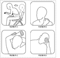
- FIG. 3 is a diagram for explaining a specific operation in the embodiment.
- FIG. 3 shows a schematic diagram of a person who performs a specific operation. Further, although FIG. 3 shows four types of specific movements, the number of types of specific movements used in the present embodiment is not particularly limited.
- the specific movement is a movement that a person can take when fatigue accumulates.
- an example of the specific motion shown as the specific motion A in the figure is an motion in which a person changes his / her posture from a backward leaning posture to a forward leaning posture.
- a person performs a specific motion A for changing the posture from the backward leaning posture to the forward leaning posture.
- an example of the specific motion shown as the specific motion B in the figure is a motion in which a person grabs the shoulder.
- the muscles become stiff, so-called stiff shoulders.
- a person performs a specific action B as an action of loosening the shoulder muscles.
- an example of the specific motion shown as the specific motion C in the figure is a motion in which a person stretches his / her back muscles by stretching his / her arm.
- the muscles of the back contract hard.
- a person performs a specific motion C of stretching an arm linked to the back muscles.
- an example of the specific motion shown as the specific motion D in the figure is a motion in which a person holds his / her head.
- a specific action D in which the person touches the painful head so as to hold it down.
- these specific movements are composed of equivalent information comparable to the joint position model for comparison with the posture of the subject 11 estimated by the posture estimation unit 25.
- a specific motion is defined by the continuous change of multiple postures, a comparison is made between the multiple joint position models and the postures estimated in both the changing order of the joint position models. Will be.
- the specific motion is provided with a permissible range in the time domain and the spatial domain in the posture determined to correspond to the specific motion. ..
- the specific movement corresponds to the movement that a general person takes when fatigue (or a load similar to fatigue on joints and muscles) accumulates.
- the specific motion is not limited to the four types of motion described above, and any motion that appears during fatigue accumulation may be applied.
- an operation peculiar to the target person 11 may be included. That is, although it is rare for a general person to appear as an action during fatigue accumulation, a motion that is frequently appearing as an action for the subject 11 during fatigue accumulation may be included as a specific action.
- the estimation of the degree of fatigue in the estimation device 100 can be made into a form specialized for the subject 11.
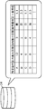
- FIG. 4 is a diagram for explaining personal fatigue information in the embodiment.
- FIG. 4 shows personal fatigue information stored in the storage unit 24.
- the personal fatigue information is associated with information corresponding to the subject 11 who is a predetermined individual for each of the specific actions. That is, when the estimation of the fatigue degree of a plurality of subjects 11 using the fatigue estimation system 200 is assumed, a plurality of personal fatigue information is prepared in a 1: 1 correspondence with the number of the plurality of subjects 11.
- the maximum number of times (maximum number of times in a day) and the minimum number of times (minimum number of times in a day) in a predetermined period are associated with each specific action. ..
- the maximum number of times in the day associated with the specific operation A is 12 times
- the minimum number of times in the day is 3 times.
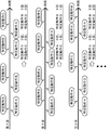
- FIG. 5 is a diagram for explaining a method of constructing personal fatigue information in the embodiment.
- FIG. 5 shows a method of determining the maximum number of times during the day and the minimum number of times during the day when constructing personal fatigue information.
- the number of times the target person 11 performs a specific operation in one day is counted.
- the specific action A is counted as 3 times
- the specific action B is counted as 3 times
- the specific action C is counted as 2 times
- the specific action D is counted as 0 times.
- the specific action A is counted as 3 times
- the specific action B is counted as 3 times
- the specific action C is counted as 1 time
- the specific action D is counted as 1 time.
- the specific action A is counted as 3 times
- the specific action B is counted as 2 times
- the specific action C is counted as 1 time
- the specific action D is counted as 2 times.
- the number of days with the most specific actions and the number of days with the least specific actions are obtained. be able to.
- the number of days with the most specific movements and the number of days with the least number of specific actions obtained are determined as the maximum number of days and the minimum number of days, respectively.
- the accuracy and accuracy of the maximum number of times during the day and the minimum number of times during the day change depending on how many times (that is, how many days) the above-mentioned specific operation is counted over a predetermined period. Therefore, the user of the fatigue estimation system 200 can count the number of times the specific operation is performed as described above until the maximum number of times in the day and the minimum number of times in the day are obtained with desired accuracy and accuracy, and construct the personal fatigue information. good.
- the first fatigue degree accumulated every time the subject 11 performs the specific action A is calculated based on the maximum number of times in the day and the minimum number of times in the day determined as described above. .. More specifically, using the maximum number of times in the day and the minimum number of times in the day associated with each of the specific movements, the first fatigue in each of the specific movements is performed by the formula of 10 / ⁇ (maximum number of times in the day)-(minimum number of times in the day) ⁇ . The degree is calculated.
- the first fatigue degree is a value representing the magnitude of the fatigue degree accumulated each time a specific motion is counted, and is a value uniquely determined by the maximum number of times in the day and the minimum number of times in the day.
- the personal fatigue information includes information on the first fatigue degree and the first fatigue degree for determining the first fatigue degree (here, the maximum number of times in the day and the minimum number of times in the day).
- the first fatigue level is a value uniquely determined from the information related to the first fatigue level. Therefore, if the personal fatigue information includes the information related to the first fatigue level, the first fatigue level itself. May not be included.
- the above formula is a formula used in the present embodiment in which the degree of fatigue is scored at 10 points, and when scoring with other values, the numerical value of 10 of the numerator in the formula may be changed. good.
- the first fatigue degree of the specific operation A is 10 / (12-3) ⁇ 1.1
- the first fatigue degree of the specific operation B is 10 / (4-1) ⁇ 3.3
- the first fatigue degree of the specific operation C is 10 / (6-0) ⁇ 1.7
- the first fatigue degree of the specific motion A is 2.4
- the first fatigue degree of the specific motion B is 1.0
- these first fatigue degrees are specified.
- the first fatigue degree of the operation C is 5.0
- the first fatigue degree of the specific operation D is 3.3 (neither is shown). In this way, the degree of fatigue accumulated until the specific action is performed differs for each subject 11.
- by constructing personal fatigue information for each subject 11 it is possible to estimate the degree of fatigue that reflects the individual habits of the specific movement to be performed.
- the personal fatigue information in the present embodiment is a fatigue part that links the fatigue part, which is the body part of the subject 11 in which the first fatigue degree for each specific movement is accumulated, with the specific movement.
- the fatigue site information links the specific motion A with the waist, which is the fatigue site corresponding to the specific motion A. That is, when the subject 11 performs the specific motion A, the first fatigue degree of 1.1 is accumulated on the waist. Similarly, when the subject 11 performs the specific motion B, the first fatigue level of 3.3 is on the shoulder, and when the subject 11 performs the specific motion C, the first fatigue level of 1.7 on the back is the specific motion.
- D 2.5 first fatigue degrees are accumulated on the shoulders, respectively.
- the specific motion B and the specific motion D are associated with the same shoulder as a fatigued part.
- the fatigue level obtained by averaging the finally accumulated fatigue levels may be calculated, and the specific motion B and the specific motion D are weighted in advance.
- the integrated fatigue degree may be calculated at a ratio corresponding to the weighting coefficient.
- the weighting coefficient here is determined according to the frequency and number of times of each specific posture when constructing personal fatigue information.
- FIG. 6 is a diagram for explaining the estimation of the degree of fatigue in the embodiment.
- the posture of the subject 11 and the timing of the specific operation from the middle of the predetermined period to the end of the predetermined period are shown in chronological order.
- the subject 11 performs the specific motion D after continuing the work in the forward leaning posture (hereinafter referred to as fatigue posture A) for 30 minutes, and returns to the fatigue posture A. ..
- the subject 11 performs the specific operation B after continuing the work in the fatigued posture A for 30 minutes, and a blank period of 2 minutes occurs due to the subject 11 moving away from the angle of view of the image pickup apparatus 101. ..
- the subject 11 continues the work in the backward leaning posture (hereinafter referred to as fatigue posture B) for 45 minutes, then performs the specific motion A, and returns to the fatigue posture A. Further, the subject 11 continues the work in the fatigued posture A for 30 minutes, and then the predetermined period ends.
- the specific operation C will be described as being performed five times.
- the determination unit 26 counts the specific operation A as 8 times, the specific operation B as 3 times, the specific operation C as 5 times, and the specific operation D as 6 times.
- the fatigue estimation unit 27 accumulates 6.6 fatigue levels on the shoulders from the specific motion B, 8.5 fatigue levels on the back from the specific motion C, and 5.0 on the shoulders from the specific motion D. It is calculated that the degree of fatigue is accumulated.
- the specific motion B and the specific motion D represent the degree of fatigue of the shoulder, which is the same fatigue portion, and the fatigue estimation unit 27 calculates the average value as the degree of fatigue of the shoulder. Specifically, here, the degree of shoulder fatigue is 5.8.
- FIG. 7 is a diagram for explaining a blank period in the embodiment.
- the fatigue estimation unit 27 integrates a predetermined supplementary fatigue degree according to the length of the blank period, and obtains the result of the integration. The above value is added to the previously calculated fatigue level.
- the subject 11 takes a break for 2 minutes, and the fatigue estimation unit 27 integrates, for example, -0.05 per minute as the supplementary fatigue degree. Therefore, the fatigue level of the subject 11 is partially recovered, and the fatigue level of 5.7 on the shoulder, the fatigue level of 8.4 on the back, and the fatigue level of 5.4 on the waist are accumulated. It is calculated. If another work is performed outside the angle of view of the image pickup apparatus 101 during the blank period, the compensation fatigue degree corresponding to the work is accumulated, and the fatigue degree of the subject 11 increases.
- the behavior schedule may be acquired from an external schedule management server or the like (not shown) and automatically determined, or the target person 11 himself / herself is a fatigue estimation system. You may input to 200.
- the fatigue estimation unit 27 makes a correction for considering the degree of fatigue accumulated by the fatigue posture A after the eighth specific operation A in FIG. Specifically, the posture of the subject 11 after a predetermined timing within a predetermined period and before the subject 11 performs a specific operation is stored in the storage unit 24 or the like together with the degree of fatigue accumulated per unit time. The fatigue estimation unit 27 uses this to estimate the degree of fatigue of the subject 11 since the last specific motion was performed.
- the predetermined timing is at the start of a predetermined period, immediately after a specific operation is performed, immediately after a blank period, or the like. In other words, the duration of one fatigued posture is sandwiched between the predetermined timing and the timing of the specific operation.
- the fatigue estimation unit 27 calculates the degree of fatigue accumulated per unit time by the fatigue posture sandwiched between the predetermined timing and the timing of the specific operation.
- the fatigue posture D is performed after the fatigue posture A before the sixth specific motion D is continued for 30 minutes. It is considered that the fatigue causing the specific motion D was caused by the fatigue posture A for 30 minutes. Therefore, the fatigue estimation unit 27 divides the first fatigue degree 2.5 of the specific operation D by 30 minutes, so that the fatigue degree accumulated per minute of the fatigue posture A (that is, the second fatigue degree) is 0. Calculated as .08. Since the fatigued portion of the specific motion D is set on the shoulder, the fatigued posture A here is also stored in the storage unit 24 on the assumption that a fatigue level of 0.08 per minute is accumulated on the shoulder. NS.
- the second fatigue degree accumulated on the shoulder due to the fatigue posture A is calculated, but there is a difference in the calculated values. Therefore, the fatigue estimation unit 27 determines that the fatigue posture A accumulates a fatigue level of 0.10 on the shoulder per minute by taking the average value of these, and stores the information stored in the storage unit 24. Update.
- the fatigue estimation unit 27 stores the second fatigue degree in the storage unit 24 by the same calculation for other fatigue postures.
- the fatigue estimation unit 27 stores in the storage unit 24 for a period during which the fatigue degree cannot be estimated using the specific movement, as in the fatigue posture A after the eighth specific movement A in FIG. 2
- the fatigue level of the subject 11 including the relevant period is estimated with reference to the fatigue level.
- the fatigue estimation unit 27 makes a correction based on the fatigue feeling so that the fatigue degree considering the subjective fatigue feeling of the subject 11 is estimated. Specifically, the fatigue estimation unit 27 receives input of information on the feeling of fatigue from the subject 11, and corrects the degree of fatigue based on the received information.
- the fatigue estimation system 200 displays a question such as "How tired do you feel?" To the subject 11 after the end of the predetermined period by the output unit 28 and the display device 105, and as an answer to the question. , Acquire a feeling of fatigue of the subject 11.
- the input by the target person 11 is received via the reception device 102 and is acquired by the second acquisition unit 22.
- the acquired fatigue feeling includes the fatigue feeling corresponding to the shoulders, back, and waist, respectively, and the fatigue estimation unit 27 estimates the fatigue degree by using the average value of the acquired fatigue degree and the calculated fatigue degree. Output as a value.
- the fatigue estimation unit 27 calculates the average value of the acquired fatigue feeling and the calculated fatigue degree.
- the fatigue estimation unit 27 outputs the estimation result to the output unit 28 assuming that the shoulder has a fatigue level of 7.9, the back has a fatigue level of 7.7, and the waist has a fatigue level of 5.7.
- FIG. 8 is a diagram for explaining the correction of the degree of fatigue in the embodiment.
- a graph is shown in which the accumulated data set is plotted by arranging the acquired fatigue feeling on the X-axis and the calculated fatigue degree on the Y-axis.
- the calculated fatigue level is higher than the acquired fatigue level. Therefore, for example, when the correlation function is obtained by regression analysis (see the broken line in the figure), the slope is 1 or less. It has become.
- FIG. 9 is a diagram illustrating information output from the fatigue estimation system according to the embodiment.
- FIG. 10 is a second diagram illustrating information output from the fatigue estimation system according to the embodiment.
- image data indicating the degree of fatigue of the subject 11 is displayed on the display module 105a of the display device 105 by the output from the output unit 28.
- the display device 105 a display provided in the computer 100a of the subject 11 is used, but other displays may be used.
- the display device 105 may be a dedicated display for the fatigue estimation system 200.
- the image data shows the degree of fatigue of the subject 11 separately for each body part.
- the image data includes a "stiff shoulder degree” indicating the degree of shoulder fatigue of the subject 11, a "back pain degree” indicating the degree of back fatigue, and a “backache degree” indicating the degree of back pain.
- the image data includes the position of each body part showing the degree of fatigue in the doll, the evaluation of the overall degree of fatigue, and the estimation result of the degree of fatigue. Explanations and advice are shown.
- advice may be given on a posture in which the degree of fatigue is relatively likely to accumulate.
- the fatigue posture A having the highest degree of second fatigue is taken up, and an image of the fatigue posture A is displayed together with a sentence indicating that the posture is particularly prone to accumulate fatigue.
- FIG. 11 is a flowchart showing the operation of the fatigue estimation system according to the embodiment.
- the fatigue estimation unit 27 reads out the personal fatigue information stored in the storage unit 24 (step S101).
- the personal fatigue information read out here is information in which the specific motion, the fatigued portion, and the information regarding the first fatigue degree are associated with each other.
- the image pickup device 101 has started operation in advance, and a plurality of images constituting a moving image are continuously output from the image pickup device 101.
- the first acquisition unit 21 starts acquiring the output image (acquisition step S102), and thereafter continuously acquires a plurality of images until the fatigue estimation system 200 is stopped.
- the posture estimation unit 25 estimates the posture of the target person 11 based on the acquired image (step S103).
- the determination unit 26 determines whether or not the movement of the target person 11 due to the change in the posture of the target person 11 estimated by the posture estimation unit 25 corresponds to the specific movement included in the personal fatigue information. It is determined whether or not the specific operation has been performed by step 11 (step S104). When a plurality of specific actions are included, it is sequentially determined whether or not the actions of the target person 11 correspond to each of the plurality of specific actions.
- step S104 When it is determined that the target person 11 is performing the specific operation (Yes in step S104), the determination unit 26 counts the number of specific operations by adding +1 to the number of specific operations (step S105). .. Then, the process proceeds to step S106. On the other hand, if it is not determined that the target person 11 is performing the specific operation (No in step S104), step S105 is skipped and the process proceeds to step S106.
- step S106 the determination unit 26 determines whether or not the predetermined period has elapsed. If it is determined that the predetermined period has not elapsed (No in step S106), the process returns to step S103, and the estimation of the posture of the subject 11 and the determination of the presence / absence of the specific motion are repeated. On the other hand, when it is determined that the predetermined period has elapsed (Yes in step S106), the fatigue estimation unit 27 estimates the fatigue degree of the subject 11 according to the number of counted specific movements (estimation step S107). .. After that, the estimation device 100 initializes the number of specific operations and ends the operation in preparation for the next estimation of the degree of fatigue.
- the fatigue level of the subject 11 can be estimated only by determining whether or not the specific operation has been performed. It is also possible to combine with a plurality of correction means for improving the accuracy of the estimated fatigue degree of the subject 11 and applying it to the individual subject 11, and the fatigue of the subject 11 or the subject 11 It is possible to easily construct a fatigue estimation system 200 according to the accuracy required by a manager or the like who manages the degree. In this way, the fatigue estimation system 200 in the present embodiment can more appropriately estimate the degree of fatigue of the subject 11.
- the fatigue estimation system 200 in the present embodiment is a fatigue estimation system 200 from an information output device (for example, an image pickup device 101) that outputs information regarding the position of a body part of the subject 11 and an information output device within a predetermined period. Based on the output information, the estimation device 100 that estimates and outputs the degree of fatigue of the subject 11 accumulated within a predetermined period by counting the number of specific actions that appear according to the fatigue accumulation. Be prepared.
- an information output device for example, an image pickup device 101
- the fatigue degree of the subject 11 can be estimated only by counting the number of such specific movements. This simplifies the calculation process for estimating the degree of fatigue of the subject 11. Therefore, in the fatigue estimation system 200 of the present embodiment, the fatigue degree of the subject 11 can be estimated more appropriately.
- the fatigue estimation system 200 is a reception device that receives an input of a fatigue feeling based on the subjectivity of the subject 11 accumulated within a predetermined period, which is a fatigue feeling corresponding to the fatigue degree of the subject 11.
- the estimation device 100 may include 102 and correct and output the fatigue level of the subject 11 based on the feeling of fatigue.
- the feeling of fatigue based on the subjectivity of the subject 11 can be reflected in the estimated value of the degree of fatigue, and the estimation of the degree of fatigue with reduced discomfort for the subject 11 can be realized. Therefore, in the fatigue estimation system 200 of the present embodiment, the fatigue degree of the subject 11 can be estimated more appropriately.
- the fatigue estimation system 200 further stores personal fatigue information including information on the first fatigue degree, which is the fatigue degree accumulated each time a specific motion is counted, of the subject 11.
- the estimation device 100 may estimate the fatigue degree of the subject 11 by including the storage unit 24) and integrating the first fatigue degree according to the number of specific operations.
- the fatigue degree of the subject 11 can be estimated more appropriately.
- the personal fatigue information may include fatigue part information that links the fatigue part, which is the body part of the subject 11 whose first fatigue degree is accumulated every time the specific movement is counted, with the specific movement.
- the estimation device 100 uses the posture of the subject 11 estimated based on the information as the fatigue posture after the predetermined timing within the predetermined period and before the specific motion of the subject 11 is counted.
- the first fatigue level is divided by the duration of the fatigued posture to calculate the second fatigue level, which is the first fatigue level accumulated by the fatigued posture per unit time, and the calculated second fatigue level is used by the subject.
- the degree of fatigue of 11 may be corrected and output.
- the estimation device 100 estimates the posture of the target person 11 based on the information output after the specific movement is last counted, and the target person estimated after the specific movement is last counted. It is determined whether the posture of 11 corresponds to the fatigue posture, and the calculated value obtained by integrating the second fatigue degree according to the duration of the posture corresponding to the fatigue posture is the fatigue of the subject 11. It may be added to the output.
- the estimation device 100 may output presentation information for presenting the fatigued posture to the subject 11.
- an acquisition device 103 for acquiring personal information including at least one of the age, gender, height, weight, muscle mass, stress level, body fat percentage, and exercise proficiency level of the subject 11.
- the estimation device 100 may correct and output the degree of fatigue of the subject 11 using the acquired personal information.
- the acquisition device 103 may acquire personal information by connecting to an external device 104 in which a health diagnosis result including personal information is stored.
- personal information can be acquired at once based on the results of health examinations in which a large amount of personal information is collectively managed. Therefore, by making corrections based on various personal information, more accurate estimation of the degree of fatigue can be easily realized, and the degree of fatigue of the subject 11 can be estimated more appropriately.
- the estimation device 100 is obtained by accumulating a preset compensation fatigue degree according to the length of the blank period in a blank period, which is a period within a predetermined period during which the information output device cannot output information.
- the fatigue degree of the subject 11 may be corrected and output using the calculated value.
- the complementation can be performed by the predetermined supplementary fatigue degree, and the images are more accurately accumulated within a predetermined period. It is possible to estimate the degree of fatigue. Therefore, it is possible to more appropriately estimate the degree of fatigue of the subject 11.
- the fatigue estimation method in the present embodiment is based on the acquisition step S102 for acquiring information on the position of the body part of the subject 11 and the specified information that appears according to the fatigue accumulation within a predetermined period based on the output information. It includes an estimation step S107 for estimating the degree of fatigue of the subject 11 accumulated within a predetermined period by counting the number of movements.
- this embodiment can also be realized as a program for causing a computer to execute the fatigue estimation method described above.
- another processing unit may execute the processing executed by the specific processing unit.
- the order of the plurality of processes may be changed, or the plurality of processes may be executed in parallel.
- the fatigue estimation system or the estimation device in the present disclosure may be realized by a plurality of devices having a part of each of the plurality of components, or may be realized by a single device having all of the plurality of components. good. Further, a part of the functions of the components may be realized as the functions of another component, and each function may be distributed to each component in any way. It is included in the present disclosure if it has a configuration having substantially all the functions that can realize the fatigue estimation system or the estimation device of the present disclosure.
- each component may be realized by executing a software program suitable for each component.
- Each component may be realized by a program execution unit such as a CPU or a processor reading and executing a software program recorded on a recording medium such as a hard disk or a semiconductor memory.
- each component may be realized by hardware.
- each component may be a circuit (or an integrated circuit). These circuits may form one circuit as a whole, or may be separate circuits from each other. Further, each of these circuits may be a general-purpose circuit or a dedicated circuit.
- the general or specific aspects of the present disclosure may be realized by a recording medium such as a system, an apparatus, a method, an integrated circuit, a computer program, or a computer-readable CD-ROM. Further, it may be realized by any combination of a system, an apparatus, a method, an integrated circuit, a computer program and a recording medium.
- the posture of the subject is estimated using a sensor module including a position sensor and a potential sensor.
- a sensor module including a position sensor and a potential sensor a plurality of sensor modules will be described as being mounted on the target person, but the number of sensor modules mounted on the target person is not particularly limited. Only one sensor module may be attached to the subject.
- the mounting style of the sensor module is not particularly limited, and any style may be used as long as the position of a predetermined body part of the subject can be measured. As an example, by wearing a costume to which a plurality of sensor modules are attached, these plurality of sensor modules are attached to the subject.
- the sensor module is a device that is attached to a predetermined body part of the subject and outputs information indicating the result of detection or measurement in conjunction with the predetermined body part.
- the sensor module has a position sensor that outputs position information regarding the spatial position of a predetermined body part of the subject, and a potential sensor that outputs potential information indicating a potential in the predetermined body part of the subject. ..
- a sensor module having both a position sensor and a potential sensor is shown, but if the sensor module has a position sensor, the potential sensor is not essential.
- the position sensor in such a sensor module is an example of an information output device that outputs position information as information regarding the position of a body part of a subject.
- the output information is position information, and is information including the relative or absolute position of a predetermined body part of the subject. Further, the output information may include, for example, potential information.
- the electric potential information is information including the electric potential value measured in a predetermined body part of the subject.
- the position sensor is a detector that detects the spatial relative position or the absolute position of the predetermined body part of the subject to which the sensor module is mounted and outputs the information regarding the spatial position of the predetermined body part which is the detection result. ..
- the information regarding the spatial position includes information that can specify the position of the body part in the space as described above and information that can specify the change in the position of the body part due to the body movement. Specifically, the information regarding the spatial position includes the position in the space of the joint and the skeleton and the information indicating the change of the position.
- the position sensor is composed of a combination of various sensors such as an acceleration sensor, an angular velocity sensor, a geomagnetic sensor, and a distance measuring sensor. Since the position information output by the position sensor can be approximated to the spatial position of the predetermined body part of the subject, the posture of the subject can be estimated from the spatial position of the predetermined body part.
- the potential sensor is a detector that measures the potential in a predetermined body part of the subject to which the sensor module is attached and outputs information indicating the potential of the predetermined body part as the measurement result.
- the potential sensor is a measuring instrument having a plurality of electrodes and measuring the potential generated between the plurality of electrodes by an electrometer.
- the potential information output by the potential sensor indicates the potential generated in the predetermined body part of the subject, and since the potential corresponds to the action potential of the muscle in the predetermined body part, the action potential of the predetermined body part It is possible to improve the estimation accuracy of the posture of the subject estimated from the above.
- the degree of fatigue of the subject is estimated using the posture of the subject estimated as described above. Since the processing after the estimation of the posture of the subject is the same as that of the above embodiment, the description thereof will be omitted.
- a ⁇ muscle load + b ⁇ joint load in which a, b, and c are coefficients (in other words, a weighting coefficient).
- a method of estimating the degree of fatigue of a subject from the posture of the subject based on the formula of amount + c ⁇ blood flow.
- the muscle load amount and the joint load amount here are non-unit index amounts normalized within the range of 0 to 1 when the amount having the Newton unit is 1 when the preset maximum value is 1. be.
- the blood flow rate here is a unitless index amount in the range of 0 to 1 obtained as a ratio of the measured value equal to or less than the initial value to the initial value.
- the above formula is an example of using three index quantities, but if at least one of the three index quantities is used, the degree of fatigue of the subject can be estimated.
- the fatigue degree of the subject is calculated as a value within the range of 0 to 1 in the same manner as described above.
- the degree of fatigue suitable for each individual is calculated a plurality of times by another method. Since the calculation result of these a plurality of times corresponds to one specific operation described above, the same degree of fatigue can be obtained. That is, by adjusting various parameters so that the calculation results of these multiple times all match, the parameters for which the fatigue degree suitable for each individual is estimated are determined even by other methods.
- the estimation device has a, b, and c as coefficients, and a ⁇ muscle load + b ⁇ joint load + c ⁇ blood flow.
- the fatigue degree of the subject is estimated based on the formula, the fatigue degree in the period corresponding to one specific operation is calculated multiple times based on the formula, and a, b, and c are referred to as the plurality of times. It can also be corrected based on the calculation result.
- the estimation result based on the formula of a ⁇ muscle load + b ⁇ joint load + c ⁇ blood flow rate as another means for estimating the degree of fatigue of the subject was described in the above embodiment.
- the coefficients of a, b, and c can be corrected so that the degree of fatigue suitable for each individual is estimated. That is, based on the fatigue degree calculated in the present embodiment, the other fatigue degree estimation methods can be corrected so as to be suitable for each individual, and the versatility of the other fatigue degree estimation methods can be improved. It can also be used to expand.
- the present disclosure may be realized as a fatigue estimation method executed by a fatigue estimation system or an estimation device.
- the present disclosure may be realized as a program for causing a computer to execute such a fatigue estimation method, or may be realized as a computer-readable non-temporary recording medium in which such a program is recorded. ..
- Target person 24 Storage unit (storage device) 100 Estimator 101 Imaging device (information output device) 102 Reception device 103 Acquisition device 104 External device 200 Fatigue estimation system
Abstract
疲労推定システム(200)は、対象者(11)の身体部位の位置に関する情報を出力する情報出力装置(例えば、撮像装置(101))と、所定期間内に情報出力装置から出力された情報に基づいて、疲労蓄積に応じて出現する特定動作の回数をカウントすることにより、所定期間内に蓄積された対象者(11)の疲労度を推定して出力する推定装置(100)と、を備える。
Description
本開示は、対象者の疲労度を推定するための疲労推定システム、疲労推定方法、及び、プログラムに関する。
近年、疲労の蓄積から体調不良をはじめ、怪我及び事故等につながるといった事例が散見される。これに対して、疲労の程度を推定することにより、体調不良、怪我及び事故等を未然に防ぐ技術が注目されるようになった。例えば、上記の疲労の程度にあたる疲労度を推定するための疲労推定システムとして、力計測、及び生体電気インピーダンス計測に基づいて疲労の有無及び疲労の種類を判定する、疲労判定装置が開示されている(特許文献1参照)。
ところで、上記の疲労度の推定は、適切に行えていない場合がある。そこで、本開示では、対象者の疲労度をより適切に推定する疲労推定システム等を提供する。
本開示の一態様に係る疲労推定システムは、対象者の身体部位の位置に関する情報を出力する情報出力装置と、所定期間内に前記情報出力装置から出力された前記情報に基づいて、疲労蓄積に応じて出現する特定動作の回数をカウントすることにより、前記所定期間内に蓄積された前記対象者の疲労度を推定して出力する推定装置と、を備える。
また、本開示の一態様に係る疲労推定方法は、対象者の身体部位の位置に関する情報を取得する取得ステップと、出力された前記情報に基づいて、所定期間内における疲労蓄積に応じて出現する特定動作の回数をカウントすることにより、前記所定期間内に蓄積された前記対象者の疲労度を推定する推定ステップと、を含む。
また、本開示の一態様は、上記に記載の疲労推定方法をコンピュータに実行させるためのプログラムとして実現できる。
本開示の一態様に係る疲労推定システム等は、対象者の疲労度をより適切に推定することができる。
以下、実施の形態について、図面を参照しながら具体的に説明する。なお、以下で説明する実施の形態は、いずれも包括的又は具体的な例を示すものである。以下の実施の形態で示される数値、形状、材料、構成要素、構成要素の配置位置及び接続形態、ステップ、ステップの順序などは、一例であり、本開示を限定する主旨ではない。また、以下の実施の形態における構成要素のうち、独立請求項に記載されていない構成要素については、任意の構成要素として説明される。
なお、各図は模式図であり、必ずしも厳密に図示されたものではない。また、各図において、実質的に同一の構成に対しては同一の符号を付し、重複する説明は省略又は簡略化される場合がある。
(実施の形態)
[システム構成]
はじめに、実施の形態における疲労推定システムの全体構成について図1及び図2を参照しながら説明する。図1は、実施の形態における疲労推定システムの概要を説明する概略図である。図1では、疲労推定システム200を用いて、対象者11の疲労度の推定が実施されている様子が示されている。図1に示された場面では、対象者11は、椅子12に着座し、テーブル13の上に置かれたコンピュータ100aを操作している。
[システム構成]
はじめに、実施の形態における疲労推定システムの全体構成について図1及び図2を参照しながら説明する。図1は、実施の形態における疲労推定システムの概要を説明する概略図である。図1では、疲労推定システム200を用いて、対象者11の疲労度の推定が実施されている様子が示されている。図1に示された場面では、対象者11は、椅子12に着座し、テーブル13の上に置かれたコンピュータ100aを操作している。
本実施の形態では、疲労推定システム200は、撮像装置101において撮像された対象者11の画像に基づいて対象者11の疲労度の推定を実施する。撮像装置101が撮像した画像は、インターネット等のネットワークを介して、推定装置100へと送信される。推定装置100は、例えば、クラウドサーバ等のサーバ装置に実装された計算処理装置であり、画像に基づいて、当該画像に含まれる対象者11の疲労度の推定を行う。推定結果は、例えば、ネットワークを介して対象者11が操作するコンピュータ100aへと送信され、コンピュータ100aの画面上に表示される、又は、記憶装置(後述する記憶部24など)に蓄積される。
この場合では、対象者11は、コンピュータ100aを用いた作業中に、同じコンピュータ100a上に表示される推定結果を確認することができる。なお、本実施の形態では上記に説明したようにサーバ装置によって推定装置100が実現される例を説明するが、疲労推定システム200の構成はこれに限られない。例えば、推定装置100はコンピュータ100aに内蔵することもできる。つまり、コンピュータ100aは、別の実施の形態での推定装置である。
推定装置としてコンピュータ100aを用いる場合、ネットワーク及びサーバ装置を備える必要がないので、撮像装置101とコンピュータ100aとの簡易な構成で疲労推定システム200を実現できる。また、コンピュータ100aには、対象者11を撮像できる位置にカメラが設けられる場合があり、当該カメラを上記の撮像装置101として利用することで、コンピュータ100aのみで疲労推定システム200を実現することも可能である。
本開示では、推定装置100において、対象者11の姿勢から対象者11の疲労度の推定を行う際、対象者11の疲労蓄積に応じて出現する特定動作の回数を、所定期間の間でカウントすることにより、簡易な計算処理で当該所定期間の間に蓄積された対象者11の疲労度を推定することができる。所定期間は、対象者11又は対象者11の疲労度を管理する管理者等の疲労推定システム200のユーザによって設定される期間であり、1時間、8時間、1日、3日、1週間、1か月等、あらゆる期間が設定できる。本実施の形態では、所定期間を1日として、日内に対象者11に蓄積された疲労度を推定する疲労推定システム200を説明する。
また、このような特定動作の回数と蓄積される疲労度との関係は、対象者11ごとに異なる場合があるため、本実施の形態では、対象者11に合わせてあらかじめ構築された個人疲労情報を用いることで、対象者11に適合した疲労度の推定結果を得ることができる。上記により、簡易な計算処理によって対象者11の疲労度を推定することができ、さらに、ここでは対象者11ごとに適合した疲労度の推定を実現できる。
図2は、実施の形態における疲労推定システムの機能構成を示すブロック図である。図2に示すように、本実施の形態における疲労推定システム200は、推定装置100、撮像装置101、受付装置102、取得装置103、外部装置104、及び、表示装置105を備える。
推定装置100は、上記したように、対象者11に蓄積された疲労度を推定する処理装置であり、サーバ装置に実装されて実現される。推定装置100は、第1取得部21、第2取得部22、第3取得部23、記憶部24、姿勢推定部25、判定部26、疲労推定部27、及び、出力部28を備える。
第1取得部21は、対象者11が撮像された画像を取得する通信モジュールである。第1取得部21は、例えば、撮像装置101において撮像された画像を、ネットワークを介して撮像装置101と通信することで取得する。
撮像装置101は、対象者11を含む画像を撮像することにより出力する装置であり、例えば、監視カメラ等の施設に設置されたカメラ、コンピュータ100a又は携帯端末等に内蔵されたカメラ、及び、疲労推定システム200の専用のカメラ等によって実現される。なお、撮像装置101が出力し、第1取得部21によって取得される画像は、時系列に沿って連続的に撮像されたいわゆる動画像である。第1取得部21は、このような動画像を撮像装置101による撮像に並行して取得する。第1取得部21は、取得した画像を姿勢推定部25へと出力する。
姿勢推定部25は、第1取得部21から出力された画像に基づいて、対象者11の姿勢を推定する処理部である。姿勢推定部25は、プロセッサ及びメモリ等により所定のプログラムが実行されることで実現される。上記したように、画像は、時系列上で連続したフレーム画像から成る動画像であるため、姿勢推定部25は、動画像を構成するフレーム画像の各々について対象者11の姿勢を推定する。これにより、姿勢推定部25からは、疲労度の推定が行われる所定期間の全期間にわたって、推定された対象者11の姿勢が出力される。ただし、対象者11が撮像装置101の画角内から離れた際には、姿勢推定部25は、対象者11の姿勢の推定を停止してもよい。
姿勢推定部25は、所定のプログラムによって画像処理を行うことで、画像に含まれる対象者11の画像内での関節位置を特定する。姿勢推定部25は、姿勢推定の結果として、関節同士の相対位置によって2つの関節間を所定の長さの骨格が接続することで表現される関節位置モデルを出力する。なお、関節位置モデルは、関節間を接続する骨格同士の相対位置と1対1に対応するため、骨格位置モデルと読み替えてもよい。推定装置100では、ここで出力される対象者11の姿勢をもとに、対象者11における疲労蓄積に応じて出現する特定動作の回数をカウントすることで、対象者11の疲労度を推定する。
また、特定動作に関する情報として、個人疲労情報が記憶部24に格納されている。記憶部24は、半導体メモリ、磁気記憶媒体、及び、光学記憶媒体等によって実現される記憶装置である。記憶部24には、個人疲労情報を含む、推定装置100において使用される各種情報が格納されている。推定装置100の各処理部等は、記憶部24から必要な情報を読出すことで当該情報を使用し、必要に応じて、各処理部が生成等した情報を新たに記憶部24に書込む。特定動作と個人疲労情報とについては、図3~図5を参照して後述する。
姿勢推定部25によって推定された対象者11の姿勢に基づく、特定動作の回数のカウントは、推定された対象者11の姿勢の変化による対象者11の動作が、特定動作に該当するか否かの判定に基づいて行われる。この判定は、判定部26によって行われる。判定部26は、上記機能を有する処理部であり、プロセッサ及びメモリ等により所定のプログラムが実行されることで実現される。判定部26は、上記のように、推定された対象者11の姿勢に基づく動作が、特定動作に該当するか否かを判定することにより、特定動作が行われたか否かを判定する。判定部26は、対象者11の動作が特定動作に該当すると判定した場合には、当該特定動作の回数に1を加算する。
疲労推定部27は、特定動作の回数に応じて対象者11の疲労度を推定する処理部である。疲労推定部27は、プロセッサ及びメモリ等により所定のプログラムが実行されることで実現される。疲労推定部27の詳細な動作については後述する。
疲労推定部27は、対象者11の疲労度を推定する際に、特定動作の回数に応じて算出された疲労度を補正することで、より正確な疲労度の推定を行う。疲労度の補正には、疲労推定部27に加えて第2取得部22及び第3取得部23が関与する。第2取得部22は、対象者11が入力した、対象者11の主観に基づく疲労感を取得する通信モジュールである。第2取得部22は、例えば、対象者11が入力した疲労感を、ネットワークを介して受付装置102と通信することで取得する。
受付装置102は、対象者11による入力を受け付ける装置であり、インターフェースデバイス等の装置によって実現される。疲労推定システム200では、対象者11に対して主観による疲労感がどの程度であるかを入力させ、入力された疲労感を用いて、算出した疲労度の補正を行う。疲労感を用いた補正については後述する。なお、疲労感には、疲労度と比較可能な同等の情報が含まれている。
第3取得部23は、対象者11の個人情報を取得する通信モジュールである。第3取得部23は、例えば、対象者11の個人情報を含む健康診断結果を、ネットワークを介して取得装置103と通信することで取得する。取得装置103は、例えば、対象者11の個人情報を含む健康診断結果を、健康診断結果が格納された外部装置104等とネットワークを介して通信することで取得する。ここでの外部装置104は、例えば、健康診断を実施する病院等の施設のサーバ、健康診断の実施を仲介する業者のサーバ、及び、対象者11を含む会社員の健康診断結果を格納した社内のサーバ等である。なお、第3取得部23は、単に、対象者11自身が受付装置102等を介して入力した個人情報を取得してもよい。
ここで、対象者11の個人情報とは、対象者11の年齢、性別、身長、体重、筋肉量、ストレス度、体脂肪率、及び、運動に対する習熟度のうちの少なくとも一つを含む情報である。対象者11の年齢は、具体的な数値であってもよく、10代、20代、及び30代のように、10歳ごとに区分された年齢帯であってもよく、59歳以下又は60歳以上のように所定の年齢を境とした二区分の年齢帯であってもよく、その他であってもよい。
また、対象者11の性別は、男性又は女性の二者のうちから選択される、対象者11に適切な一方である。また、身長及び体重としては、対象者11の身長及び体重の数値がそれぞれ取得される。また、筋肉量は、体組成計等を用いて計測された対象者11の筋肉の組成比率として取得される。また、ストレス度は、対象者11が感じる主観的なストレスの程度として、高度、中度及び低度等の選択肢の中から対象者11自身の選択によって決定された情報である。
また、対象者11の運動に対する習熟度は、所定の運動プログラムを対象者11が実施した際のスコアで定量化されていてもよく、対象者11が普段取り組む運動の状況であってもよい。前者では、例えば、背筋を10回行うのに要した時間、50mを走るのに要した時間、遠投の飛距離等によって定量化される。後者では、例えば、一週間に何日運動を行うか、又は何時間運動を行うか等によって定量化される。なお、個人情報は、推定される疲労度の正確度を向上する目的で使用されるため、十分な正確度が確保される場合には、第3取得部23、取得装置103、及び外部装置104を備えずに疲労推定システム200を実現してもよい。
疲労推定部27は、取得された個人情報に基づいて、特定動作の回数をカウントした結果から算出した疲労度を補正することで、最終的に推定装置100から出力される疲労度の推定を行う。個人情報を用いた疲労度の補正では、例えば、対象者11の年齢が筋肉の発達のピーク年齢に近いほど疲労度を小さくし、当該ピーク年齢から離れるほど疲労度を大きくする。このようなピーク年齢は対象者11の性別に基づいて決定されてもよい。また、対象者11の性別が男性であれば疲労度を小さく、女性であれば疲労度を大きくしてもよい。また、対象者11の身長及び体重が小さい値であるほど疲労度を小さく、身長及び体重が大きい値であるほど疲労度を大きくしてもよい。
また、対象者11の筋肉量が大きい組成比率であるほど疲労度を小さく、筋肉量が小さい組成比率であるほど疲労度を大きくしてもよい。また、対象者11のストレス度が低いほど疲労度を小さく、ストレス度が高いほど疲労度を大きくしてもよい。また、対象者11の体脂肪率が高いほど疲労度を大きく、体脂肪率が低いほど疲労度を小さくしてもよい。さらに、対象者11の運動に対する習熟度が高いほど疲労度を小さく、運動に対する習熟度が低いほど疲労度を大きくしてもよい。
疲労推定部27は、以上のようにして、特定動作の回数に応じた疲労度をさらに補正することで、対象者11ごとのより正確な疲労度の推定を行う。疲労推定部27は、推定によって得られた疲労度を出力部28に出力する。
出力部28は、推定された疲労度を含む推定結果を対象者11に提示させるための提示情報として出力する処理部である。出力部28は、プロセッサ及びメモリ等により所定のプログラムが実行されることで実現される。出力部28は、疲労推定部27において推定された対象者11の疲労度に、その他の情報を併せた提示情報である画像データを生成し、ネットワークを介して表示装置105へと送信する。また、出力部28は、提示情報として音声データを生成してもよく、この場合、音声データを出音装置(不図示)へと送信する。
表示装置105は、受信した画像データを表示する装置である。表示装置105は、液晶パネル等の表示モジュール105a(後述する図9参照)を有するディスプレイであり、表示モジュール105aを駆動することにより、出力部28から受信した画像データを表示する。
以下、特定動作及び個人疲労情報について、図3~図5を参照して説明する。図3は、実施の形態における特定動作を説明するための図である。図3では、特定動作を行う人の模式図が示されている。また、図3では、特定動作として4種類の例を示しているが、本実施の形態で用いられる特定動作の種類の数に特に限定はない。
特定動作は、上記に説明したように、疲労蓄積の際に人がとり得る動作である。例えば、図中に特定動作Aとして示す特定動作の一例は、人が後傾姿勢から前傾姿勢へと姿勢を変更する動作である。後傾姿勢で何らかの作業を行うと、腰に疲労が蓄積するため、人は、蓄積した疲労を緩和するために後傾姿勢から前傾姿勢へと姿勢を変更する特定動作Aを行う。
また、例えば、図中に特定動作Bとして示す特定動作の一例は、人が肩をつかむ動作である。人が、腕を挙げた状態での作業を続ける等によって、肩の筋肉を継続的に使用すると筋肉が硬くなる、いわゆる肩こりの状態になる。人は、硬くなった筋肉を弛緩させるために、肩の筋肉をほぐす動作として特定動作Bを行う。
また、例えば、図中に特定動作Cとして示す特定動作の一例は、人が腕をのばすことにより背の筋肉をのばす動作である。人が座位及び立位等で、あまり体を動かすことなく作業を続けると、背の筋肉が硬く収縮する。人は、収縮した背の筋肉をのばすため、背の筋肉に連動する腕をのばす特定動作Cを行う。
また、例えば、図中に特定動作Dとして示す特定動作の一例は、人が頭を押さえる動作である。上記と同様にして肩こりなどの状態によって血流が悪化した際、頭痛の症状を生じることがあり、人は、痛みのある頭を押さえるように触ってしまう特定動作Dを行う。なお、これらの特定動作は、上記の姿勢推定部25によって推定された対象者11の姿勢との比較のため、関節位置モデルと比較可能な同等の情報から構成されている。ただし、特定動作は、複数の姿勢が連続的に変化することで定義されるため、複数の関節位置モデルと、当該関節位置モデルの変化する順序との両方において推定された姿勢との比較が行われる。また、特定動作と推定された姿勢とが完全に一致することは稀であるため、特定動作には、特定動作に該当すると判定される姿勢に時間領域及び空間領域において許容範囲が設けられている。
特定動作は、一般的な人において疲労(又は疲労に準じる関節及び筋肉等への負荷)が蓄積した際に、当該人がとってしまう動作に対応している。特定動作としては、上記に説明した4種類の動作に限らず、疲労蓄積の際に出現するあらゆる動作が適用されてもよい。また、特定動作として、対象者11に特有の動作が含まれてもよい。すなわち、一般の人にとって疲労蓄積の際に出現する動作として稀であるものの、対象者11にとって疲労蓄積の際に出現する動作として高頻度である動作が特定動作として含まれてもよい。本実施の形態では、このように、個人疲労情報に含まれる特定動作の構成を適切化することによって、推定装置100における疲労度の推定を対象者11に特化した形態にすることもできる。
以降の実施の形態では、上記の4種類の特定動作を用いて対象者11の疲労度の推定を行う例を説明する。ここでの特定動作は、一般に疲労時に出現する動作であるため、一般的な人すべての疲労推定に適用可能な推定装置100が実現される。また以降の説明では、特定動作A~特定動作Dを特に断りなく説明に使用する場合があるが、それぞれの特定動作の詳細は、上記の図3の説明を参照することにより説明が省略される。
図4は、実施の形態における個人疲労情報について説明するための図である。図4には、記憶部24に格納された個人疲労情報が示されている。図中に示すように、個人疲労情報には、特定動作のそれぞれについて、所定の個人である対象者11に対応する情報が紐づけられている。つまり、疲労推定システム200を用いた複数の対象者11の疲労度の推定が想定される場合、個人疲労情報は、複数の対象者11の数と1:1の対応で複数準備される。
図中に示すように、個人疲労情報では、特定動作の各々には、所定期間である一日の中での最大回数(日内最大回数)及び最小回数(日内最小回数)が紐づけられている。例えば、特定動作Aに紐づけられた日内最大回数は12回であり、日内最小回数は3回である。ここで、日内最大回数及び日内最小回数の決定方法を説明する。図5は、実施の形態における個人疲労情報の構築方法について説明するための図である。図5では、個人疲労情報を構築する際の日内最大回数及び日内最小回数を決定する方法が示されている。
本実施の形態のように、所定期間として1日が設定されている場合、1日の中で対象者11が特定動作を行った回数のカウントを行う。例えば、図中では、第1日において、特定動作Aが3回、特定動作Bが3回、特定動作Cが2回、特定動作Dが0回とカウントされている。同様に、第2日において、特定動作Aが3回、特定動作Bが3回、特定動作Cが1回、特定動作Dが1回とカウントされている。同様に、第3日において、特定動作Aが3回、特定動作Bが2回、特定動作Cが1回、特定動作Dが2回とカウントされている。
このように複数回の所定期間にあたる複数日にわたって繰り返して、上記の特定動作を行った回数のカウントを行うことで、特定動作が最も多かった日の回数と、最も少なかった日の回数とを得ることができる。得られた、特定動作の最も多かった日の回数、及び、最も少なかった日の回数が、それぞれ日内最大回数及び日内最小回数として決定される。
日内最大回数及び日内最小回数は、上記の、特定動作を行った回数のカウントが、所定期間何回分(つまり、何日分)にわたって行われたかによって精度及び正確度が変化する。したがって、疲労推定システム200のユーザは、所望の精度及び正確度で日内最大回数及び日内最小回数が得られるまで、上記の、特定動作を行った回数のカウントを行い、個人疲労情報を構築すればよい。
再び図4を参照して、上記のようにして決定された日内最大回数及び日内最小回数をもとに、対象者11が特定動作Aを行うごとに蓄積される第1疲労度が算出される。より詳しくは、特定動作の各々に紐づけられた日内最大回数及び日内最小回数を用いて、10/{(日内最大回数)-(日内最小回数)}の式によって特定動作の各々における第1疲労度が算出される。第1疲労度は、特定動作がカウントされるごとに蓄積される疲労度の大きさを表す値であり、日内最大回数及び日内最小回数によって一意に決定される値である。
個人疲労情報は、図中に示すように、第1疲労度及び第1疲労度を決定するための第1疲労度に関する情報(ここでは、日内最大回数及び日内最小回数)を含む。なお、上記のように、第1疲労度は、第1疲労度に関する情報から一意に決定される値であるため、個人疲労情報に第1疲労度に関する情報が含まれれば、第1疲労度そのものは含まれていなくてもよい。また、上記の式では、疲労度を10点で点数化する本実施の形態において用いられる式であり、その他の値で点数化する場合には、式中の分子の10の数値を変更すればよい。
図中では、特定動作Aの第1疲労度は、10/(12-3)≒1.1であり、特定動作Bの第1疲労度は、10/(4-1)≒3.3であり、特定動作Cの第1疲労度は、10/(6-0)≒1.7であり、特定動作Dの第1疲労度は、10/(8-4)=2.5である。これらの第1疲労度は、別の対象者11では、例えば、特定動作Aの第1疲労度は、2.4であり、特定動作Bの第1疲労度は、1.0であり、特定動作Cの第1疲労度は、5.0であり、特定動作Dの第1疲労度は、3.3である(いずれも不図示)。このように、対象者11ごとに特定動作が行われるまでに蓄積される疲労度が異なる。本実施の形態では、対象者11ごとに個人疲労情報を構築することで、行われる特定動作の個人ごとの癖が反映された疲労度の推定が可能となる。
また、図中に示すように、本実施の形態における個人疲労情報は、特定動作ごとの第1疲労度が蓄積される対象者11の身体部位である疲労部位と特定動作とを紐づける疲労部位情報を含む。例えば、疲労部位情報は、特定動作Aと、特定動作Aに対応する疲労部位である腰とを紐づけている。つまり、対象者11が、特定動作Aを行った場合、腰に1.1の第1疲労度が蓄積される。同様に、対象者11が、特定動作Bを行った場合、肩に3.3の第1疲労度が、特定動作Cを行った場合、背に1.7の第1疲労度が、特定動作Dを行った場合、肩に2.5の第1疲労度がそれぞれ蓄積される。
ここで、特定動作Bと特定動作Dとは、疲労部位として同じ肩が紐づけられている。この場合、特定動作B及び特定動作Dのそれぞれにおいて、最終的に蓄積された疲労度を平均した疲労度が算出されてもよく、特定動作Bと特定動作Dとで、あらかじめ設定された重みづけ係数に従って、当該重みづけ係数に応じた比率で一体化された疲労度が算出されてもよい。ここでの重みづけ係数は、個人疲労情報を構築する際の各々の特定姿勢の頻度及び回数等に応じて決定される。
次に、図6~図8を参照して、対象者11の疲労度の推定等について説明する。図6は、実施の形態における疲労度の推定について説明するための図である。図6では、所定期間の途中から、所定期間の終了までの間の、対象者11の姿勢と、特定動作のタイミングとが、時系列に沿って示されている。具体的には、図示された期間において、対象者11は、前傾姿勢(以下、疲労姿勢Aという)での作業を30分間継続した後に、特定動作Dを行い、疲労姿勢Aに戻っている。さらに、対象者11は、疲労姿勢Aでの作業を30分継続した後、特定動作Bを行い、対象者11が撮像装置101の画角内から離れることによる2分間の空白期間が生じている。対象者11は、後傾姿勢(以下疲労姿勢Bという)での作業を45分間継続した後に、特定動作Aを行い、疲労姿勢Aに戻る。さらに、対象者11は、疲労姿勢Aでの作業を30分継続した後、所定期間が終了する。なお、特定動作Cは5回行われているものとして説明する。
この場合、判定部26は、特定動作Aが8回、特定動作Bが3回、特定動作Cが5回、特定動作Dが6回とカウントする。ここで、カウントされた特定動作の回数から疲労度を算出する際、日内最小回数のときを疲労度0として規格化が行われる。したがって、疲労推定部27は、特定動作の回数から日内最小回数を差引いた差分の回数に第1疲労度を乗算して疲労度の算出を行う。例えば、疲労推定部27は、特定動作Aが8回であったため、1.1×(8-3)=5.5となり、特定動作の回数に基づいて、対象者11の腰に5.5の疲労度が蓄積されると算出する。
同様に、疲労推定部27は、特定動作Bから肩に6.6の疲労度が蓄積され、特定動作Cから背に8.5の疲労度が蓄積され、特定動作Dから肩に5.0の疲労度が蓄積されると算出する。ここで、特定動作Bと特定動作Dとは、同じ疲労部位である肩の疲労度を表しており、疲労推定部27は、平均値を肩の疲労度として算出する。具体的には、ここでは、肩の疲労度が5.8となる。
次に、図7を参照して、空白期間における対象者11の疲労度の補正について説明する。図7は、実施の形態における空白期間について説明するための図である。図7に示すように、撮像装置101の画角内から対象者11が離れてしまうと、画像に基づく疲労度の推定を行うことができない空白期間が形成される。そこで本実施の形態では、このような空白期間が形成された場合、疲労推定部27は、当該空白期間の長さに応じて、あらかじめ定められた補填疲労度を積算し、積算の結果得られた数値を先に算出された疲労度に加算する。
例えば、図6の例では、対象者11が2分間の休憩を行った場合であり、疲労推定部27は、補填疲労度として、例えば、1分あたり-0.05を積算する。したがって、対象者11の疲労度は、一部回復し、肩に5.7の疲労度、背に8.4の疲労度、及び、腰に5.4の疲労度がそれぞれ蓄積していると算出される。なお、空白期間に、撮像装置101の画角の外側で別の作業を行った場合、当該作業に応じた補填疲労度が積算され、対象者11の疲労度が増加する。このような、空白期間における対象者11の行動については、外部のスケジュール管理サーバ等(不図示)から行動予定を取得して自動的に判別してもよいし、対象者11が自ら疲労推定システム200に入力を行ってもよい。
次に、本実施の形態では、疲労推定部27は、図6中の8回目の特定動作Aの後の疲労姿勢Aによって蓄積される疲労度を考慮するための補正を行う。具体的には、所定期間内の所定タイミング以降かつ対象者11が特定動作を行う以前の対象者11の姿勢を単位時間あたりに蓄積される疲労度とともに記憶部24等に格納する。疲労推定部27は、これを用いて、特定動作が最後に行われた以降の対象者11の疲労度を推定する。なお、所定タイミングは、所定期間の開始時、特定動作が行われた直後、又は、空白期間の直後等である。言い換えると、所定タイミングと、特定動作のタイミングとによって、1つの疲労姿勢の継続期間が挟まれる。疲労推定部27は、このように所定タイミングと特定動作のタイミングとによって挟まれた疲労姿勢によって単位時間あたりに蓄積される疲労度を算出する。
例えば、図中の例では、6回目の特定動作Dの前の疲労姿勢Aが30分継続された後に、疲労姿勢Dを行うに至っている。特定動作Dを行うに至った原因となる疲労は、30分間の疲労姿勢Aによってもたらされたと考えられる。したがって、疲労推定部27は、特定動作Dの第1疲労度2.5を30分で除することにより、疲労姿勢Aの1分あたりに蓄積される疲労度(つまり第2疲労度)が0.08と算出する。なお、特定動作Dは、疲労部位が肩に設定されているため、ここでの疲労姿勢Aについても同様に1分あたり0.08の疲労度が肩に蓄積されるとして記憶部24に格納される。
また、疲労推定部27は、図中の6回目の特定動作D以降かつ3回目の特定動作B以前の疲労姿勢Aについて、同様に、肩への第2疲労度が、3.3/30分=0.11と算出し、記憶部24に格納する。ここで、上記の2つの計算例では、ともに、疲労姿勢Aによる肩に蓄積される第2疲労度の算出を行っているが、算出される値に差がある。したがって、疲労推定部27は、これらの平均値をとることにより、疲労姿勢Aが1分あたりに肩へ0.10の疲労度を蓄積するものと決定し、記憶部24に格納された情報を更新する。疲労推定部27は、その他の疲労姿勢についても同様の計算により、記憶部24に第2疲労度を格納する。
その後、疲労推定部27は、図6中の8回目の特定動作Aの後の疲労姿勢Aのように、特定動作を用いた疲労度の推定が行えない期間について、記憶部24に格納した第2疲労度を参照して当該期間を含む対象者11の疲労度の推定を行う。例えば図中の例では、疲労度の推定が行えない期間において対象者11は、疲労姿勢Aをとっている。したがって1分あたりに肩へ0.10の疲労度が蓄積されるとして、30分×0.10=3.0となる。よって、疲労推定部27は、先に算出した疲労度と併せて、肩に8.7の疲労度、背に8.4の疲労度、及び、腰に5.4の疲労度がそれぞれ蓄積されると推定する。
また、以上に説明した推定結果は、撮像された画像から推定されたのみであるため、対象者11が実際に感じている疲労感と一致しない場合がある。疲労度の推定において、対象者11の主観による疲労感との乖離が生じると、対象者11が違和感を覚える可能性がある。本実施の形態では、疲労推定部27は、対象者11の主観による疲労感を考慮した疲労度が推定されるように疲労感に基づく補正を行う。具体的には、疲労推定部27は、対象者11から、疲労感に関する情報の入力を受け付け、受け付けた情報をもとに疲労度の補正を行う。
例えば、疲労推定システム200は、出力部28及び表示装置105によって、所定期間の終了後に、対象者11に、「どの程度疲労を感じていますか?」等の質問を表示し、これに対する回答として、対象者11の疲労感を取得する。対象者11による入力は受付装置102を介して受け付けられ、第2取得部22によって取得される。取得された疲労感には、肩、背、及び、腰に対応する疲労感がそれぞれ含まれ、疲労推定部27は、取得した疲労度と、算出した疲労度との平均値を疲労度の推定値として出力する。
ここでは、一例として対象者11によって、肩に7.0の疲労感、背に7.0の疲労感、及び、腰に6.0の疲労感があると入力されたものとする。疲労推定部27は、取得した疲労感と算出した疲労度との平均値を算出する。疲労推定部27は、肩に7.9の疲労度、背に7.7の疲労度、及び、腰に5.7の疲労度がそれぞれ蓄積されたとして推定結果を出力部28に出力する。
また、このように、算出した疲労度と、取得した疲労感とのデータセットが複数蓄積されると、相関関係を求めることができる。例えば、図8は、実施の形態における疲労度の補正について説明するための図である。図中では、取得した疲労感をX軸に、算出された疲労度をY軸に配して、蓄積されたデータセットをプロットしたグラフを示している。図中の例では、算出された疲労度が取得された疲労度よりも高い値となっているため、例えば回帰分析により相関関数を求めた場合(図中の破線参照)、傾きが1以下となっている。
したがって、算出された疲労度を上記の相関関数に代入することで、対象者11からの入力を受け付けることなく、違和感が低減された疲労度を推定することも可能である。
出力部28からは、表示装置105へと画像が出力される。この出力結果について、図9及び図10を参照して説明する。図9は、実施の形態における疲労推定システムから出力される情報を例示する第1図である。また、図10は、実施の形態における疲労推定システムから出力される情報を例示する第2図である。
図9に示すように、出力部28からの出力により、表示装置105の表示モジュール105aに、対象者11の疲労度を示す画像データが表示されている。この、表示装置105としては、対象者11のコンピュータ100aに備えられるディスプレイが用いられるが、その他のディスプレイであってもよい。例えば、表示装置105は、疲労推定システム200のための専用のディスプレイであってもよい。
図中に示すように、画像データには、対象者11の疲労度が、身体部位ごとに分けて示されている。具体的には、画像データには、対象者11の肩の疲労度を示す「肩こり度」、背の疲労度を示す「背部痛度」、及び、腰の疲労度を示す「腰痛度」が、それぞれ個別に示されている。また、これに加えて、付加的な情報として、画像データには、疲労度が示されている各身体部位の人形での位置、総合的な疲労度の評価、及び、疲労度の推定結果に対する解説及び助言等が示されている。
また、図10に示すように、比較的疲労度が蓄積しやすい姿勢について助言を行ってもよい。例えば、図10の例では、第2疲労度が最も大きい疲労姿勢Aを取り上げ、特に疲労が蓄積しやすい姿勢であることを示す文章とともに当該疲労姿勢Aの画像が表示されている。
[動作]
次に、以上に説明した疲労推定システム200の動作について、図11を参照して説明する。図11は、実施の形態における疲労推定システムの動作を示すフローチャートである。
次に、以上に説明した疲労推定システム200の動作について、図11を参照して説明する。図11は、実施の形態における疲労推定システムの動作を示すフローチャートである。
本実施の形態における疲労推定システム200では、はじめに、疲労推定部27が、記憶部24に格納された個人疲労情報を読出す(ステップS101)。ここで読出された個人疲労情報は、特定動作と疲労部位と第1疲労度に関する情報とが紐づけられた情報である。
撮像装置101は、あらかじめ稼働を開始しており、動画像を構成する複数の画像が撮像装置101から連続的に出力されている。第1取得部21は、出力される画像の取得を開始し(取得ステップS102)、以降、疲労推定システム200が停止されるまで連続的に複数の画像の取得を継続する。
ここで、姿勢推定部25は、取得された画像に基づいて、対象者11の姿勢を推定する(ステップS103)。判定部26は、姿勢推定部25によって推定された対象者11の姿勢の変化による対象者11の動作が、個人疲労情報に含まれる特定動作に該当するか否かを判定することで、対象者11によって特定動作が行われたか否かを判定する(ステップS104)。なお、特定動作が複数含まれる場合には、複数の特定動作のそれぞれについて、対象者11の動作が該当するか否かの判定を順次行う。
対象者11が、特定動作を行っていると判定された場合(ステップS104でYes)、判定部26は、特定動作の回数に+1を加算することで特定動作の回数をカウントする(ステップS105)。その後、ステップS106に進む。一方で、対象者11が、特定動作を行っていると判定されなかった場合(ステップS104でNo)、ステップS105をスキップしてステップS106に進む。
ステップS106では、判定部26は、所定期間が経過したか否かを判定する。所定期間が経過していないと判定された場合(ステップS106でNo)、ステップS103に戻り、対象者11の姿勢の推定及び特定動作の有無の判定を繰り返す。一方で、所定期間が経過したと判定された場合(ステップS106でYes)、疲労推定部27は、カウントされた特定動作の回数に応じて対象者11の疲労度を推定する(推定ステップS107)。その後、推定装置100は、次回の疲労度の推定に備え、特定動作の回数を初期化して動作を終了する。
本実施の形態では、以上のようにして、特定動作が行われたか否かの判定のみで対象者11の疲労度の推定を行うことができる。また、推定される対象者11の疲労度の正確度の向上、及び個別の対象者11への適用のための複数の補正手段と組み合わせることも可能であり、対象者11又は対象者11の疲労度を管理する立場の管理者等が要求する正確度に応じた疲労推定システム200を容易に構築することができる。このようにして、本実施の形態における疲労推定システム200は、対象者11の疲労度をより適切に推定することができる。
[効果等]
以上、説明したように本実施の形態における疲労推定システム200は、対象者11の身体部位の位置に関する情報を出力する情報出力装置(例えば、撮像装置101)と、所定期間内に情報出力装置から出力された情報に基づいて、疲労蓄積に応じて出現する特定動作の回数をカウントすることにより、所定期間内に蓄積された対象者11の疲労度を推定して出力する推定装置100と、を備える。
以上、説明したように本実施の形態における疲労推定システム200は、対象者11の身体部位の位置に関する情報を出力する情報出力装置(例えば、撮像装置101)と、所定期間内に情報出力装置から出力された情報に基づいて、疲労蓄積に応じて出現する特定動作の回数をカウントすることにより、所定期間内に蓄積された対象者11の疲労度を推定して出力する推定装置100と、を備える。
このような疲労推定システム200では、推定された対象者11の姿勢の変化が、疲労蓄積に応じて出現する特定動作に該当するか否かによって、対象者11が特定動作を行った回数をカウントする。対象者11の疲労度の蓄積と、カウントされる特定動作の回数とに相関があるため、このような特定動作の回数をカウントするのみで対象者11の疲労度を推定することができる。これにより、対象者11の疲労度を推定するための計算処理が簡略化される。よって、本実施の形態における疲労推定システム200では、対象者11の疲労度をより適切に推定することができる。
また、例えば、疲労推定システム200は、さらに、対象者11の疲労度に対応する疲労感であって、所定期間内に蓄積された、対象者11の主観に基づく疲労感の入力を受け付ける受付装置102を備え、推定装置100は、疲労感に基づいて、対象者11の疲労度を補正して出力してもよい。
これによれば、対象者11の主観に基づく疲労感を疲労度の推定値に反映することができ、対象者11にとって違和感が低減された疲労度の推定を実現できる。よって、本実施の形態における疲労推定システム200では、対象者11の疲労度をより適切に推定することができる。
また、例えば、疲労推定システム200は、さらに、対象者11の、特定動作がカウントされるごとに蓄積される疲労度である第1疲労度に関する情報を含む個人疲労情報が格納された記憶装置(例えば、記憶部24)を備え、推定装置100は、第1疲労度を特定動作の回数に応じて積算することで対象者11の疲労度を推定してもよい。
これによれば、対象者11ごとの特定動作の回数に現れる癖に基づき、より対象者11に適合した疲労度の推定を行うことができる。したがって、対象者11にとって違和感が低減された疲労度の推定を実現できる。よって、本実施の形態における疲労推定システム200では、対象者11の疲労度をより適切に推定することができる。
また、例えば、個人疲労情報は、特定動作がカウントされるごとに第1疲労度が蓄積される対象者11の身体部位である疲労部位と特定動作とを紐づける疲労部位情報を含んでもよい。
これによれば、対象者11の身体部位ごとの疲労度を推定することができる。よって、より詳細な身体部位ごとの疲労度の推定を実現できるため、対象者11の疲労度をより適切に推定することができる。
また、例えば、推定装置100は、所定期間内の所定タイミング以降かつ対象者11の特定動作がカウントされる以前に、情報に基づいて推定された対象者11の姿勢を疲労姿勢とした場合に、第1疲労度を疲労姿勢の継続時間で除算して、単位時間あたりに疲労姿勢によって蓄積される第1疲労度である第2疲労度を算出し、算出した第2疲労度を用いて対象者11の疲労度を補正して出力してもよい。
これによれば、所定タイミングから特定動作が行われるまでの間の姿勢に基づく第2疲労度により、より正確な対象者11の疲労度の推定を行うことができる。よって、より正確な疲労度の推定を実現でき、対象者11の疲労度をより適切に推定することができる。
また、例えば、推定装置100は、特定動作が最後にカウントされた以降に出力された情報に基づいて、対象者11の姿勢を推定し、特定動作が最後にカウントされた以降に推定した対象者11の姿勢が、疲労姿勢に該当する姿勢であるかを判定し、疲労姿勢に該当する姿勢の継続時間に応じて第2疲労度を積算して得られた計算値を、対象者11の疲労度に加算して出力してもよい。
これによれば、特定動作の回数のカウントによる疲労度の推定ができない期間を含め、第2疲労度に基づいて疲労度の推定を行うことができる。よって、より正確な疲労度の推定を実現でき、対象者11の疲労度をより適切に推定することができる。
また、例えば、推定装置100は、疲労姿勢を対象者11に提示させるための提示情報を出力してもよい。
これによれば、比較的疲労の蓄積しやすい疲労姿勢を対象者11に提示することができ、対象者11が疲労を蓄積しやすい姿勢を理解するために貢献できる。
また、例えば、さらに、対象者11の年齢、性別、身長、体重、筋肉量、ストレス度、体脂肪率、及び、運動に対する習熟度のうちの少なくとも一つを含む個人情報を取得する取得装置103を備え、推定装置100は、取得した個人情報を用いて対象者11の疲労度を補正して出力してもよい。
これによれば、各種の個人情報に基づく補正によって、より正確な疲労度の推定を行うことができる。よって、対象者11の疲労度をより適切に推定することができる。
また、例えば、取得装置103は、個人情報を含む健康診断結果が格納された外部装置104に接続することで、個人情報を取得してもよい。
これによれば、多くの個人情報が一括で管理されている健康診断結果をもとに、一挙に個人情報を取得することができる。よって、各種の個人情報に基づく補正により、より正確な疲労度の推定を容易に実現でき、対象者11の疲労度をより適切に推定することができる。
また、例えば、推定装置100は、情報出力装置が情報を出力できない所定期間内の期間である空白期間において、あらかじめ設定された補填疲労度を空白期間の長さに応じて積算して得られた計算値を用いて対象者11の疲労度を補正して出力してもよい。
これによれば、画像に対象者11が含まれず、疲労度の推定ができない場合においても、あらかじめ定められた補填疲労度によって、補完を行うことができ、より正確に所定期間内に蓄積された疲労度を推定することが可能となる。よって、対象者11の疲労度をより適切に推定することが可能となる。
また、本実施の形態における疲労推定方法は、対象者11の身体部位の位置に関する情報を取得する取得ステップS102と、出力された情報に基づいて、所定期間内における疲労蓄積に応じて出現する特定動作の回数をカウントすることにより、所定期間内に蓄積された対象者11の疲労度を推定する推定ステップS107と、を含む。
これによれば、上記疲労推定システム200と同様の効果を奏することができる。
また、本実施の形態は、上記に記載の疲労推定方法をコンピュータに実行させるためのプログラムとして実現することもできる。
これによれば、コンピュータを用いて、上記疲労推定方法と同様の効果を奏することができる。
(その他の実施の形態)
以上、実施の形態について説明したが、本開示は、上記実施の形態に限定されるものではない。
以上、実施の形態について説明したが、本開示は、上記実施の形態に限定されるものではない。
例えば、上記実施の形態において、特定の処理部が実行する処理を別の処理部が実行してもよい。また、複数の処理の順序が変更されてもよいし、複数の処理が並行して実行されてもよい。
また、本開示における疲労推定システム又は推定装置は、複数の構成要素の一部ずつを有する複数の装置で実現されてもよく、複数の構成要素のすべてを有する単一の装置で実現されてもよい。また、構成要素の機能の一部が別の構成要素の機能として実現されてもよく、各機能が各構成要素にどのように分配されてもよい。実質的に本開示の疲労推定システム又は推定装置を実現し得る機能がすべて備えられる構成を有する形態であれば本開示に含まれる。
また、上記実施の形態において、各構成要素は、各構成要素に適したソフトウェアプログラムを実行することによって実現されてもよい。各構成要素は、CPU又はプロセッサなどのプログラム実行部が、ハードディスク又は半導体メモリなどの記録媒体に記録されたソフトウェアプログラムを読み出して実行することによって実現されてもよい。
また、各構成要素は、ハードウェアによって実現されてもよい。例えば、各構成要素は、回路(又は集積回路)でもよい。これらの回路は、全体として1つの回路を構成してもよいし、それぞれ別々の回路でもよい。また、これらの回路は、それぞれ、汎用的な回路でもよいし、専用の回路でもよい。
また、本開示の全般的又は具体的な態様は、システム、装置、方法、集積回路、コンピュータプログラム又はコンピュータ読み取り可能なCD-ROMなどの記録媒体で実現されてもよい。また、システム、装置、方法、集積回路、コンピュータプログラム及び記録媒体の任意な組み合わせで実現されてもよい。
また、対象者の姿勢の推定方法として、撮像装置を用いる構成の他、位置センサを用いる構成により本開示を実現することも可能である。具体的には、位置センサ及び電位センサを含むセンサモジュールを用いて対象者の姿勢が推定される。ここでは、センサモジュールは、対象者に複数装着されるものとして説明するが、対象者に装着されるセンサモジュールの数に特に限定はない。センサモジュールが対象者に1つだけ装着されていてもよい。
また、センサモジュールの装着様式にも特に限定はなく、対象者の所定の身体部位の位置を計測できればどのような様式であってもよい。一例として、センサモジュールが複数取り付けられた衣装を着用することで、これら複数のセンサモジュールが対象者に装着されている。
センサモジュールは、対象者の所定の身体部位に装着され、当該所定の身体部位に連動するようにして検知又は計測の結果を示す情報を出力する装置である。具体的には、センサモジュールは、対象者の所定の身体部位の空間位置に関する位置情報を出力する位置センサ、及び、対象者の所定の身体部位における電位を示す電位情報を出力する電位センサを有する。図中では、位置センサ及び電位センサのいずれも有するセンサモジュールが示されているが、センサモジュールは、位置センサを有していれば、電位センサは必須ではない。このようなセンサモジュールにおける位置センサは、位置情報を対象者の身体部位の位置に関する情報として出力する情報出力装置の一例である。したがって、出力される情報は、位置情報であり、対象者の所定の身体部位の相対的又は絶対的な位置を含む情報である。また、出力される情報には、例えば、電位情報が含まれてもよい。電位情報は、対象者の所定の身体部位において計測される電位の値を含む情報である。位置情報及び電位情報について、以下、位置センサ及び電位センサとともに詳しく説明する。
位置センサは、センサモジュールが装着される対象者の所定の身体部位の空間的な相対位置又は絶対位置を検知し、検知結果である所定の身体部位の空間位置に関する情報を出力する検知器である。空間位置に関する情報は、上記のように空間内における身体部位の位置が特定可能な情報と、体動に伴う身体部位の位置の変化を特定可能な情報とを含む。具体的には、空間位置に関する情報は、関節及び骨格の空間内における位置と当該位置の変化を示す情報とを含む。
位置センサは、加速度センサ、角速度センサ、地磁気センサ、及び測距センサ等の各種のセンサを組み合わせて構成される。位置センサによって出力される位置情報は、対象者の所定の身体部位の空間位置に近似することができるため、所定の身体部位の空間位置から対象者の姿勢を推定することができる。
電位センサは、センサモジュールが装着される対象者の所定の身体部位における電位を計測し、計測結果である所定の身体部位の電位を示す情報を出力する検知器である。電位センサは、複数の電極を有し、当該複数の電極間において生じる電位を電位計によって計測する計測器である。電位センサによって出力される電位情報は、対象者の所定の身体部位において生じた電位を示し、当該電位が、所定の身体部位における筋肉の活動電位等に相当するため、所定の身体部位の活動電位等から推定される対象者の姿勢の推定精度を向上することができる。
ここで説明した疲労推定システムの一態様では、上記のようにして推定された対象者の姿勢を用いて、対象者の疲労度を推定する。なお、対象者の姿勢の推定以降の処理は、上記実施の形態と同様であるため説明を省略する。
また、上記の実施の形態において説明した対象者の疲労度の推定方法の他に、a、b、及び、cを係数(言い換えると重みづけ係数)とする、a×筋肉負荷量+b×関節負荷量+c×血流量の式に基づいて、対象者の姿勢から、対象者の疲労度を推定する手法等が存在する。なお、ここでの筋肉負荷量及び関節負荷量は、ニュートン単位を有する量が、あらかじめ設定された最大値を1とした場合の0~1の範囲内に正規化された無単位の指標量である。また、ここでの血流量は、初期値に対する、初期値以下の計測値の比として得られる0~1の範囲内の無単位の指標量である。上記の式における各係数の関係をa+b+c=1とすることで、上記の式によって算出される疲労度も0~1の範囲内の値として算出される。
また、上記の式は、3つの指標量を用いる例であるが、3つの指標量の少なくとも1つを用いれば、対象者の疲労度の推定が実施できる。この場合、指標量の各々に乗じられる重み付け係数の和を1とすることで、上記と同様に、対象者の疲労度が0~1の範囲内の値として算出される。
ただし、これらの他の手法では、上記に説明したような個人ごとに適合した疲労度の推定を行うことは困難である。また、個人ごとの疲労度が推定されるように各種のパラメータを調整することは困難である。そこで、上記の実施の形態において算出された特定動作1回分の期間に相当する疲労度を、他の手法において複数回算出する。これら複数回の算出結果は、上記の特定動作1回分に相当するため同じ疲労度が得られる。つまり、これらの複数回の算出結果が全て一致するように各種パラメータを調整することで、他の手法であっても、個人ごとに適合した疲労度が推定されるパラメータが決定される。
以上のように、前記推定装置は、前記対象者の疲労度の別の推定方法として、a、b、及び、cを係数とする、a×筋肉負荷量+b×関節負荷量+c×血流量の式に基づいて前記対象者の疲労度を推定し、前記式に基づいて前記特定動作1回分に相当する期間における疲労度を複数回算出し、a、b、及び、cを、前記複数回の算出結果に基づいて補正こともできる。
これによれば、対象者の疲労度を推定する別の手段としてのa×筋肉負荷量+b×関節負荷量+c×血流量の式に基づく推定結果に対して、上記実施の形態において説明した、個人ごとに適合した疲労度が推定されるように、a、b、及び、cの係数を補正することができる。つまり、本実施の形態において算出された疲労度をもとに、他の疲労度の推定の方法を個人ごとに適合するように補正することができ、他の疲労度の推定方法の汎用性を拡張するために利用することもできる。
また、本開示は、疲労推定システム又は推定装置が実行する疲労推定方法として実現されてもよい。本開示は、このような疲労推定方法をコンピュータに実行させるためのプログラムとして実現されてもよいし、このようなプログラムが記録されたコンピュータ読み取り可能な非一時的な記録媒体として実現されてもよい。
その他、実施の形態に対して当業者が思いつく各種変形を施して得られる形態、又は、本開示の趣旨を逸脱しない範囲で各実施の形態における構成要素及び機能を任意に組み合わせることで実現される形態も本開示に含まれる。
11 対象者
24 記憶部(記憶装置)
100 推定装置
101 撮像装置(情報出力装置)
102 受付装置
103 取得装置
104 外部装置
200 疲労推定システム
24 記憶部(記憶装置)
100 推定装置
101 撮像装置(情報出力装置)
102 受付装置
103 取得装置
104 外部装置
200 疲労推定システム
Claims (14)
- 対象者の身体部位の位置に関する情報を出力する情報出力装置と、
所定期間内に前記情報出力装置から出力された前記情報に基づいて、疲労蓄積に応じて出現する特定動作の回数をカウントすることにより、前記所定期間内に蓄積された前記対象者の疲労度を推定して出力する推定装置と、を備える
疲労推定システム。 - さらに、前記対象者の疲労度に対応する疲労感であって、前記所定期間内に蓄積された、前記対象者の主観に基づく疲労感の入力を受け付ける受付装置を備え、
前記推定装置は、前記疲労感に基づいて、前記対象者の疲労度を補正して出力する
請求項1に記載の疲労推定システム。 - さらに、前記対象者の、前記特定動作がカウントされるごとに蓄積される疲労度である第1疲労度に関する情報を含む個人疲労情報が格納された記憶装置を備え、
前記推定装置は、前記第1疲労度を前記特定動作の回数に応じて積算することで前記対象者の疲労度を推定する
請求項1又は2に記載の疲労推定システム。 - 前記個人疲労情報は、前記特定動作がカウントされるごとに前記第1疲労度が蓄積される前記対象者の身体部位である疲労部位と前記特定動作とを紐づける疲労部位情報を含む
請求項3に記載の疲労推定システム。 - 前記推定装置は、
前記所定期間内の所定タイミング以降かつ前記対象者の前記特定動作がカウントされる以前に、前記情報に基づいて推定された前記対象者の姿勢を疲労姿勢とした場合に、前記第1疲労度を前記疲労姿勢の継続時間で除算して、単位時間あたりに前記疲労姿勢によって蓄積される前記第1疲労度である第2疲労度を算出し、
算出した前記第2疲労度を用いて前記対象者の疲労度を補正して出力する
請求項3又は4に記載の疲労推定システム。 - 前記推定装置は、
前記特定動作が最後にカウントされた以降に出力された前記情報に基づいて、前記対象者の姿勢を推定し、
前記特定動作が最後にカウントされた以降に推定した前記対象者の姿勢が、前記疲労姿勢に該当する姿勢であるかを判定し、
前記疲労姿勢に該当する姿勢の継続時間に応じて前記第2疲労度を積算して得られた計算値を、前記対象者の疲労度に加算して出力する
請求項5に記載の疲労推定システム。 - 前記推定装置は、前記疲労姿勢を前記対象者に提示させるための提示情報を出力する
請求項5又は6に記載の疲労推定システム。 - さらに、前記対象者の年齢、性別、身長、体重、筋肉量、ストレス度、体脂肪率、及び、運動に対する習熟度のうちの少なくとも一つを含む個人情報を取得する取得装置を備え、
前記推定装置は、取得した前記個人情報を用いて前記対象者の疲労度を補正して出力する
請求項1~7のいずれか一項に記載の疲労推定システム。 - 前記取得装置は、前記個人情報を含む健康診断結果が格納された外部装置に接続することで、前記個人情報を取得する
請求項8に記載の疲労推定システム。 - 前記推定装置は、前記情報出力装置が前記情報を出力できない前記所定期間内の期間である空白期間において、あらかじめ設定された補填疲労度を前記空白期間の長さに応じて積算して得られた計算値を用いて前記対象者の疲労度を補正して出力する
請求項1~9のいずれか一項に記載の疲労推定システム。 - 前記推定装置は、
前記対象者の疲労度の別の推定方法として、筋肉負荷量、関節負荷量、及び血流量の少なくとも1つの指標量と、前記指標量の各々に乗じられる重み付け係数とを用いた関係式に基づいて前記対象者の疲労度を推定し、
前記特定動作1回分に相当する期間における疲労度を複数回算出した結果に基づいて、前記重み付けを補正する
請求項1に記載の疲労推定システム。 - 前記推定装置は、
前記対象者の疲労度の別の推定方法として、a、b、及び、cを係数とする、a×筋肉負荷量+b×関節負荷量+c×血流量の式に基づいて前記対象者の疲労度を推定し、
前記式に基づいて前記特定動作1回分に相当する期間における疲労度を複数回算出し、
a、b、及び、cを、前記複数回の算出結果に基づいて補正する
請求項1に記載の疲労推定システム。 - 対象者の身体部位の位置に関する情報を取得する取得ステップと、
出力された前記情報に基づいて、所定期間内における疲労蓄積に応じて出現する特定動作の回数をカウントすることにより、前記所定期間内に蓄積された前記対象者の疲労度を推定する推定ステップと、を含む
疲労推定方法。 - 請求項13に記載の疲労推定方法をコンピュータに実行させるための
プログラム。
Priority Applications (3)
| Application Number | Priority Date | Filing Date | Title |
|---|---|---|---|
| US17/924,303 US20230181075A1 (en) | 2020-05-28 | 2021-05-19 | Fatigue estimation system, fatigue estimation method, and recording medium |
| JP2022526926A JPWO2021241348A1 (ja) | 2020-05-28 | 2021-05-19 | |
| CN202180033912.7A CN115551411A (zh) | 2020-05-28 | 2021-05-19 | 疲劳推测系统、疲劳推测方法及程序 |
Applications Claiming Priority (2)
| Application Number | Priority Date | Filing Date | Title |
|---|---|---|---|
| JP2020-093032 | 2020-05-28 | ||
| JP2020093032 | 2020-05-28 |
Publications (1)
| Publication Number | Publication Date |
|---|---|
| WO2021241348A1 true WO2021241348A1 (ja) | 2021-12-02 |
Family
ID=78745109
Family Applications (1)
| Application Number | Title | Priority Date | Filing Date |
|---|---|---|---|
| PCT/JP2021/018946 WO2021241348A1 (ja) | 2020-05-28 | 2021-05-19 | 疲労推定システム、疲労推定方法、及び、プログラム |
Country Status (4)
| Country | Link |
|---|---|
| US (1) | US20230181075A1 (ja) |
| JP (1) | JPWO2021241348A1 (ja) |
| CN (1) | CN115551411A (ja) |
| WO (1) | WO2021241348A1 (ja) |
Cited By (2)
| Publication number | Priority date | Publication date | Assignee | Title |
|---|---|---|---|---|
| CN115736902A (zh) * | 2022-12-01 | 2023-03-07 | 广州市汇源通信建设监理有限公司 | 一种基于智能穿戴设备的施工人员管理系统 |
| WO2023120064A1 (ja) * | 2021-12-24 | 2023-06-29 | パナソニックIpマネジメント株式会社 | 疲労推定装置、疲労推定システム、及び疲労推定方法 |
Citations (6)
| Publication number | Priority date | Publication date | Assignee | Title |
|---|---|---|---|---|
| JPH0347207A (ja) * | 1989-07-14 | 1991-02-28 | Nissan Motor Co Ltd | シート |
| JP2003325489A (ja) * | 2002-05-13 | 2003-11-18 | Toyota Central Res & Dev Lab Inc | 腰筋肉疲労判定装置 |
| WO2006054542A1 (ja) * | 2004-11-16 | 2006-05-26 | Nihon University | 疲労判定システム及び疲労判定方法 |
| JP2015150150A (ja) * | 2014-02-13 | 2015-08-24 | 富士ゼロックス株式会社 | 情報提供装置及びプログラム |
| JP2017086524A (ja) * | 2015-11-11 | 2017-05-25 | セイコーエプソン株式会社 | 疲労度管理装置、疲労度管理システムおよび疲労度判定方法 |
| JP2017194772A (ja) * | 2016-04-19 | 2017-10-26 | トヨタ自動車株式会社 | 覚醒度判定装置 |
-
2021
- 2021-05-19 CN CN202180033912.7A patent/CN115551411A/zh active Pending
- 2021-05-19 US US17/924,303 patent/US20230181075A1/en active Pending
- 2021-05-19 WO PCT/JP2021/018946 patent/WO2021241348A1/ja active Application Filing
- 2021-05-19 JP JP2022526926A patent/JPWO2021241348A1/ja active Pending
Patent Citations (6)
| Publication number | Priority date | Publication date | Assignee | Title |
|---|---|---|---|---|
| JPH0347207A (ja) * | 1989-07-14 | 1991-02-28 | Nissan Motor Co Ltd | シート |
| JP2003325489A (ja) * | 2002-05-13 | 2003-11-18 | Toyota Central Res & Dev Lab Inc | 腰筋肉疲労判定装置 |
| WO2006054542A1 (ja) * | 2004-11-16 | 2006-05-26 | Nihon University | 疲労判定システム及び疲労判定方法 |
| JP2015150150A (ja) * | 2014-02-13 | 2015-08-24 | 富士ゼロックス株式会社 | 情報提供装置及びプログラム |
| JP2017086524A (ja) * | 2015-11-11 | 2017-05-25 | セイコーエプソン株式会社 | 疲労度管理装置、疲労度管理システムおよび疲労度判定方法 |
| JP2017194772A (ja) * | 2016-04-19 | 2017-10-26 | トヨタ自動車株式会社 | 覚醒度判定装置 |
Cited By (3)
| Publication number | Priority date | Publication date | Assignee | Title |
|---|---|---|---|---|
| WO2023120064A1 (ja) * | 2021-12-24 | 2023-06-29 | パナソニックIpマネジメント株式会社 | 疲労推定装置、疲労推定システム、及び疲労推定方法 |
| CN115736902A (zh) * | 2022-12-01 | 2023-03-07 | 广州市汇源通信建设监理有限公司 | 一种基于智能穿戴设备的施工人员管理系统 |
| CN115736902B (zh) * | 2022-12-01 | 2023-07-25 | 广州市汇源通信建设监理有限公司 | 一种基于智能穿戴设备的施工人员管理系统 |
Also Published As
| Publication number | Publication date |
|---|---|
| US20230181075A1 (en) | 2023-06-15 |
| CN115551411A (zh) | 2022-12-30 |
| JPWO2021241348A1 (ja) | 2021-12-02 |
Similar Documents
| Publication | Publication Date | Title |
|---|---|---|
| US10352962B2 (en) | Systems and methods for real-time data quantification, acquisition, analysis and feedback | |
| US11679300B2 (en) | Systems and methods for real-time data quantification, acquisition, analysis, and feedback | |
| US9730583B2 (en) | Method for objective diagnostics of internuclear opthalmopligia, ocular lateral pulsion, progressive supernuclear palsy and glissades eye movements | |
| WO2021241348A1 (ja) | 疲労推定システム、疲労推定方法、及び、プログラム | |
| US20210093240A1 (en) | Systems and methods for reaction measurement | |
| US9795335B2 (en) | Data collection for vestibulogram construction | |
| JP6535778B1 (ja) | 運動能力評価システム | |
| WO2019069864A1 (ja) | 医療情報処理システム | |
| JP2020017153A (ja) | 健康状態診断システム | |
| CN111772577A (zh) | 一种基于云平台的膝关节康复评估系统及方法 | |
| Madhushri et al. | A smartphone application suite for assessing mobility | |
| Kim et al. | Missing sample recovery for wireless inertial sensor-based human movement acquisition | |
| Walsh et al. | Marker-based monitoring of seated spinal posture using a calibrated single-variable threshold model | |
| Sprint et al. | Designing wearable sensor-based analytics for quantitative mobility assessment | |
| JP6552875B2 (ja) | 移動運動解析装置、方法及びプログラム | |
| CN116114028A (zh) | 神经肌肉疾病评估系统 | |
| JP2018038753A (ja) | 歩行分析方法及び歩行分析装置 | |
| Santos-Paz et al. | A novel virtual reality application for autonomous assessment of cervical range of motion: development and reliability study | |
| CN116725520B (zh) | 一种基于脊柱矢状面实时监测的驼背矫姿系统及方法 | |
| Liu et al. | Analysis of eye tracking of physiotherapist during walk rehabilitation | |
| CN113397530B (zh) | 一种可进行膝关节功能评估的智能矫正系统和方法 | |
| WO2021241347A1 (ja) | 疲労推定システム、疲労推定方法、及び、プログラム | |
| US20240065600A1 (en) | Emotion estimating device, emotion estimating system, and emotion estimating method | |
| Nahavandi et al. | Passive muscle force analysis during vehicle access: A gender comparison | |
| JP2018055626A (ja) | 運動方法自動提示システム、及び運動方法自動提示方法 |
Legal Events
| Date | Code | Title | Description |
|---|---|---|---|
| 121 | Ep: the epo has been informed by wipo that ep was designated in this application |
Ref document number: 21813415 Country of ref document: EP Kind code of ref document: A1 |
|
| ENP | Entry into the national phase |
Ref document number: 2022526926 Country of ref document: JP Kind code of ref document: A |
|
| NENP | Non-entry into the national phase |
Ref country code: DE |
|
| 122 | Ep: pct application non-entry in european phase |
Ref document number: 21813415 Country of ref document: EP Kind code of ref document: A1 |