WO2021241111A1 - 締め付け工具 - Google Patents
締め付け工具 Download PDFInfo
- Publication number
- WO2021241111A1 WO2021241111A1 PCT/JP2021/016740 JP2021016740W WO2021241111A1 WO 2021241111 A1 WO2021241111 A1 WO 2021241111A1 JP 2021016740 W JP2021016740 W JP 2021016740W WO 2021241111 A1 WO2021241111 A1 WO 2021241111A1
- Authority
- WO
- WIPO (PCT)
- Prior art keywords
- motor
- tightening
- control mode
- tool
- control unit
- Prior art date
- Legal status (The legal status is an assumption and is not a legal conclusion. Google has not performed a legal analysis and makes no representation as to the accuracy of the status listed.)
- Ceased
Links
Images


Classifications
-
- B—PERFORMING OPERATIONS; TRANSPORTING
- B25—HAND TOOLS; PORTABLE POWER-DRIVEN TOOLS; MANIPULATORS
- B25B—TOOLS OR BENCH DEVICES NOT OTHERWISE PROVIDED FOR, FOR FASTENING, CONNECTING, DISENGAGING OR HOLDING
- B25B21/00—Portable power-driven screw or nut setting or loosening tools; Attachments for drilling apparatus serving the same purpose
- B25B21/02—Portable power-driven screw or nut setting or loosening tools; Attachments for drilling apparatus serving the same purpose with means for imparting impact to screwdriver blade or nut socket
-
- B—PERFORMING OPERATIONS; TRANSPORTING
- B25—HAND TOOLS; PORTABLE POWER-DRIVEN TOOLS; MANIPULATORS
- B25B—TOOLS OR BENCH DEVICES NOT OTHERWISE PROVIDED FOR, FOR FASTENING, CONNECTING, DISENGAGING OR HOLDING
- B25B23/00—Details of, or accessories for, spanners, wrenches, screwdrivers
- B25B23/14—Arrangement of torque limiters or torque indicators in wrenches or screwdrivers
- B25B23/147—Arrangement of torque limiters or torque indicators in wrenches or screwdrivers specially adapted for electrically operated wrenches or screwdrivers
- B25B23/1475—Arrangement of torque limiters or torque indicators in wrenches or screwdrivers specially adapted for electrically operated wrenches or screwdrivers for impact wrenches or screwdrivers
-
- B—PERFORMING OPERATIONS; TRANSPORTING
- B25—HAND TOOLS; PORTABLE POWER-DRIVEN TOOLS; MANIPULATORS
- B25B—TOOLS OR BENCH DEVICES NOT OTHERWISE PROVIDED FOR, FOR FASTENING, CONNECTING, DISENGAGING OR HOLDING
- B25B23/00—Details of, or accessories for, spanners, wrenches, screwdrivers
- B25B23/18—Devices for illuminating the head of the screw or the nut
Definitions
- the present invention relates to a tightening tool for tightening fasteners such as screws.
- the tightening tool includes a motor, a transmission mechanism connected to the motor, and a tip tool connected to the transmission mechanism.
- the operator connects the tip tool to a fastener such as a screw and transmits the rotational force of the motor to the tip tool via a transmission mechanism to perform tightening work for tightening the fastener.
- a transmission mechanism for the tightening tool As a transmission mechanism for the tightening tool, a configuration using a deceleration mechanism for decelerating the rotation of the motor and an impact mechanism for converting the continuous rotation of the motor into intermittent torque is known. It is known that such a tightening tool includes a control unit for controlling the rotation of the motor and changes the rotation state of the motor when a predetermined condition is satisfied during the tightening operation.
- a control unit for controlling the rotation of the motor and changes the rotation state of the motor when a predetermined condition is satisfied during the tightening operation.
- Patent Document 1 in order to prevent the impact mechanism from being damaged in the work of tightening a hard member with a bolt, the current flowing through the motor exceeds a predetermined value when repeated impacts are performed by the impact mechanism. And an impact tool that reduces the current flowing through the motor is disclosed.
- Patent Document 2 in order to prevent the impact mechanism from being damaged in the work of tightening a hard member with bolts, when the current flowing through the motor exceeds a predetermined value during repeated impacts by the impact mechanism, Disclosed is an impact tool that reduces the current flowing through the motor for a first predetermined period before and after the impact mechanism generates a striking force.
- Patent Document 3 in order to enable accurate tightening in the work of tightening a small screw, the duty ratio applied to the motor is lowered before the first impact by the impact mechanism is performed, and the impact is performed at a low duty ratio.
- Impact tools are disclosed.
- Patent Document 4 in order to enable high-speed and accurate tightening in the work of tightening screws and bolts, when the impact mechanism continues to hit multiple times and the current flowing through the motor exceeds a predetermined value, the screws or bolts are released.
- An impact tool that determines that the member is seated and reduces the duty ratio applied to the motor is disclosed.
- Patent Document 5 discloses an impact tool that stops the rotation of a motor when a screw sits on a member without being hit by an impact mechanism in order to enable accurate tightening of gypsum board with a screw. Has been done.
- the present invention has been made in view of the above background, and an object thereof is such that when tightening a plurality of members using fasteners such as bolts and nuts, there is a gap between the members to be tightened. It is an object of the present invention to provide a tightening tool that enables accurate tightening even in some cases. Another object of the present invention is to increase the current value due to the seated state and to make close contact between the members during tightening by using the measured current value when tightening a plurality of members with fasteners such as bolts and nuts. It is an object of the present invention to provide a tightening tool capable of performing reliable tightening work by distinguishing an increase in current value depending on a state.
- a motor a transmission mechanism connected to the motor, and a tip tool connected to the transmission mechanism so as to be able to be connected to a fastener for tightening a plurality of members separated from each other. It has a configured tip tool and a control unit configured to control the motor in a first control mode or a second control mode different from the first control mode, and when a load is applied to the tip tool, In a tightening tool configured to perform a repetitive striking motion that repeatedly transmits a rotational striking force from the transmission mechanism to the tip tool, the control unit controls a plurality of members from each other by fasteners while the repetitive striking motion is being performed.
- the control unit reduces the rotation speed of the motor when a plurality of members are brought into close contact with each other by the fastener and a predetermined condition is satisfied while the repetitive striking operation is being executed. Or, it is configured to notify the close contact. Further, the current flowing through the motor has a peak value of the current generated in substantially the same cycle as the repeated striking operation, and the control unit performs the first switching related to the peak value of the current flowing through the motor while the repetitive striking operation is being executed. When the condition is satisfied, it is determined that the plurality of members have moved to the close contact state.
- the present invention is configured to be able to be connected to a motor, a transmission mechanism connected to the motor, and a fastener for tightening a plurality of members separated from each other by a tip tool connected to the transmission mechanism.
- the reduction ratio of the deceleration mechanism in the tightening tool having the tip tool, the deceleration mechanism that decelerates the rotation of the motor as the transmission mechanism of the tightening tool, and the impact mechanism that converts the continuous rotation of the motor into intermittent torque. was configured so that the rotation speed of the impact mechanism per 5 rotations of the motor was 1 rotation or less.
- a motor a transmission mechanism connected to the motor, and a tip tool connected to the transmission mechanism so as to be able to be connected to a fastener for tightening a plurality of members separated from each other.
- the tip tool is loaded with a configured tip tool and a control unit configured to control the motor in a first control mode or a second control mode different from the first control mode.
- the transmission mechanism includes a deceleration mechanism that slows down the rotation of the motor and continuous rotation of the motor.
- the control unit controls the current flowing through the motor.
- the control of the motor is configured to be switched from the first control mode to the second control mode.
- the control unit controls the motor from the first control mode to the second when the first switching condition related to the peak value of the current flowing through the motor is satisfied while the repeated striking operation is being executed. Switch to the control mode of. Further, the control unit needs that at least the peak value of the current tends to increase and the rate of change of the peak value of the current increases in order to determine that the first switching condition is satisfied. And.
- the control unit monitors the current measured value by the current measuring unit, and the first switching condition is satisfied. At least, (1) the peak value of the current has exceeded the predetermined value, (2) the moving average value of the peak value of the current has exceeded the predetermined value, and (3) the peak of the current.
- the slope of the moving average value of the value is greater than or equal to the predetermined value, (4) any of (1) to (3) above occurs multiple times, or (5) (1) to (3) above. Any one of the following occurred in succession multiple times was made a requirement.
- the control unit calculates an integrated value in the vicinity of the peak of the current measured value (current flowing through the motor) by the current measuring unit, and performs the above control using this integrated value as the peak value of the current.
- the control unit determines, as the second control mode, (a) stop the rotation of the motor, (b) reduce the rotation speed of the motor, or (c). )
- the notification unit is configured to notify.
- the control unit determines that the second switching condition is satisfied, at least (e) the repeated striking operation is executed a predetermined number of times after the first switching condition is satisfied, or (f) the first. 1 It is configured to require one of the fact that the repetitive striking operation is executed for a predetermined time after the switching condition is satisfied.
- a tightening system comprising a tightening tool and a fastener fastened by the tightening tool, wherein the tightening tool is a motor, a tip tool rotationally driven by the motor, and the like.
- a detection unit that detects physical information related to the load applied to the motor, and a control unit configured to control the motor in a first control mode or a second control mode different from the first control mode.
- the control unit has a determination algorithm configured to determine the tightening state of the fastener using machine learning based on the physical information input from the detection unit and generate a determination result.
- the control unit is a tightening system configured to shift the control of the motor from the first control mode to the second control mode according to the judgment result by the judgment algorithm.
- a machine learning device configured to generate a determination algorithm for determining a tightening state of a fastener fastened by a tightening tool, which is related to a load applied to the motor of the tightening tool.
- Machine learning by a genetic algorithm is executed based on the input unit configured to input the tightening data corresponding to the physical information to be used and the tightening state of the fastener, and the tightening data input to the input unit. It has a generator configured to generate a determination algorithm for determining the tightening state.
- the magnitude of the tightening torque transmitted from the tip tool to the fastener during the striking operation is large. Can be accurately estimated from the peak value of the current, so that tightening can be performed with an accurate tightening torque regardless of the state of the tightening target.
- FIG. 3 is a graph showing the relationship between the passage of time, the peak value 82 of the current of the motor 3, and the moving average 83 of the peak value of the current when the nut 62 is tightened to the tightening target shown in FIG. It is an enlarged view of the current waveform of a motor 3, and is the figure for demonstrating the detection method of the moving average 83 of the peak value 82 of a current.
- FIG. 1 is a side view showing the appearance of the impact tool 1 according to the embodiment of the present invention.
- the impact tool 1 uses a rechargeable pack-type battery 90 (see FIG. 2 for reference numerals) as a power source, and uses a motor 3 as a drive source to apply rotational force and striking force to the output shaft (anvil 40) to the tool holding portion 41.
- the rotary striking force is intermittently transmitted to a tip tool such as a socket wrench held in the pin through hole 42 to perform operations such as screw tightening and bolt tightening.
- a tool holding portion 41 is formed at the front end of the anvil 40, to which a tip tool such as a socket 50 is attached, and a fastening member such as a screw or a bolt is tightened or loosened to a mating material.
- the socket 50 is an example of the "tip tool" of the present invention.
- the tool holding portion 41 has a square cross-sectional shape orthogonal to the rotation axis A1, and a pin through hole 42 for mounting a pin for preventing falling off is formed at the center of two of the four outer peripheral surfaces.
- the housing 2 of the impact tool 1 extends in a direction substantially orthogonal to the rotation axis A1 from a substantially cylindrical body portion 2a for accommodating the motor 3 and a transmission mechanism described later and a substantially central portion of the body portion 2a. It has a substantially T-shaped shape having a handle portion 2b for the operator to grip with one hand. Of the ends of the handle portion 2b, a battery mounting portion (not shown) is formed at a lower end portion (anti-body portion side end portion) located on the opposite side of the body portion 2a, and a battery (not shown) is mounted.
- a trigger lever 7a is arranged so as to project forward in the upper part of the handle portion 2b, and a trigger switch 7 for switching on or off the rotation of the motor 3 is provided on the rear side of the trigger lever 7a.
- a forward / reverse switching lever 8 for switching the rotation direction of the motor 3 in the forward direction or the reverse direction is provided.
- the motor 3 is housed on the rear side of the cylindrical body portion 2a.
- the motor 3 is a DC (direct current) motor without a brush (rectifying brush), and is a 4-pole 6-slot brushless DC motor.
- the motor 3 includes a rotor (rotor) 3a provided with a permanent magnet and a stator (stator) 3b provided with a multi-phase armature winding (stator winding) such as a three-phase winding.
- the rotor 3a forms a magnetic path formed by a permanent magnet.
- the stator 3b is manufactured by a laminated structure of an annular thin iron plate, and six teeth (not shown) are formed on the inner peripheral side, and an enamel wire is wound around each tooth to form a coil.
- the coil is a star connection having three phases of U, V, and W.
- the motor 3 uses the output of the position detection element 13 composed of a plurality of Hall ICs for detecting the magnetic force of the permanent magnet of the rotor 3a to detect the rotor position, and uses the output of the position detection element 13 to transmit the DC voltage supplied from the battery or the like to a plurality of semiconductors. It operates by being switched by the switching element 14 (.
- the rotary shaft 4 of the motor 3 is arranged concentrically with the rotary axis A1 of the tubular body portion 2a, and is pivotally supported by the housing 2 by two bearings 16a and 16b on the front side and the rear side.
- a substantially annular inverter circuit board 12 for mounting three position detection elements 13, six semiconductor switching elements 14, and the like is arranged on the rear side of the stator 3b.
- the inverter circuit board 12 is a substantially annular double-sided board having a diameter substantially the same as the outer diameter of the motor 3.
- Six semiconductor switching elements 14 are provided to form an inverter circuit 80 (described later in FIG. 2), and the energization of the stator windings of each phase is switched.
- FETs field effect transistors
- IGBTs insulated gate bipolar transistors
- the inverter circuit is controlled by a microcomputer (microcomputer 71 described later in FIG. 2), and the energization timing of the armature winding of each phase is set based on the position detection result of the rotor 3a by the position detection element 13, so that the rotation is high. It becomes easy to control.
- a cooling fan 15 is mounted coaxially with the rotating shaft 4 between the rotor 3a and the bearing 16a.
- the cooling fan 15 is integrally molded by, for example, a plastic mold, and sucks air from an air intake port (not shown) formed near the rear end side of the body portion 2a. The sucked air cools the mounted element of the inverter circuit board 12, and then passes between the rotor 3a and the stator 3b and flows forward on the outer peripheral side of the stator 3b to cool the motor 3.
- the air that has reached the cooling fan 15 is discharged radially outward due to the rotation of the cooling fan 15, and is discharged to the outside through air discharge slits (not shown) formed on the left and right side surfaces of the cooling fan 15.
- a cup-shaped hammer case 5 is provided on the front side of the housing 2.
- the hammer case 5 houses the deceleration mechanism 20 and the impact mechanism 25 inside, and is provided on the front side of the body portion 2a of the housing 2.
- the hammer case 5 is made of an integral metal product, and a through hole 5a for penetrating the anvil 40 is formed in a front portion corresponding to a cup-shaped bottom. It is the outside of the hammer case 5 and serves as a tool holding portion 41 for attaching or detaching a tip tool (not shown) to the tip portion of the anvil 40.
- a lighting device 9 using an LED is provided on the lower side near the front end of the hammer case 5.
- a trigger lever 7a is arranged so as to project forward from the upper part of the handle portion 2b extending integrally from the body portion 2a of the housing 2 at a substantially right angle, and the user grips the handle portion 2b with one hand, and the index finger or the like is used.
- the trigger pushing amount operation amount
- the rotation direction of the motor 3 can be switched between the tightening direction and the loosening direction by operating the forward / reverse switching lever 8.
- the body portion 2a of the housing 2 is manufactured by integrally molding a synthetic resin material together with the handle portion 2b, and is formed so as to be split into two left and right on a vertical surface passing through the rotation shaft 4 of the motor 3.
- the left side member and the right side member of the housing 2 are prepared, and the deceleration mechanism 20 and the impact mechanism 25 are incorporated in advance in one housing 2 (for example, the left housing) as shown in the cross-sectional view of FIG.
- the hammer case 5 and the motor 3 and the like are assembled, and then the other housing 2 (for example, the housing on the right side) is overlapped and tightened with a plurality of screws.
- the impact mechanism 25 is provided on the output side of the speed reduction mechanism 20 using planetary gears, includes a spindle 26 and a hammer 30, and is rotatably held by a bearing 18b at the rear end and a metal bearing 18a at the front end.
- the reduction mechanism 20 is provided in the space between the sun gear 21 fixed to the tip of the rotating shaft 4 of the motor 3, the ring gear 23 provided on the outer peripheral side of the sun gear 21 so as to surround the sun gear 21 at a distance, and the space between the sun gear 21 and the ring gear 23. It comprises a plurality of planetary gears 22 that are arranged and meshed with both of these gears.
- the ring gear 23 is also called an outer gear, and a gear is formed on the inner peripheral surface of the ring-shaped member.
- the outer peripheral surface of the ring gear 23 is held by the housing 2 via the inner cover 19.
- the main role of the inner cover 19 is to hold the two bearings 18b and 16a provided, and to coaxially center the rotation axis 4 of the motor 3 and the rotation center of the spindle 26.
- the bearing 18b held by the inner cover 19 is for supporting the rotating shaft 4 of the motor 3, for example, a ball bearing is used.
- the bearing 18b held by the inner cover 19 is for pivotally supporting the rear end of the spindle 26, and for example, a ball bearing is used.
- a plurality of (three in this case) planetary gears 22 are pivotally supported by a planetary carrier portion formed at the rear end of the spindle 26, and the planetary gears 22 rotate around a shaft pivotally supported by the planetary carrier portion. While revolving around the sun gear 21.
- the ring gear 23 itself does not rotate.
- the sun gear 21 also rotates in synchronization with the rotation. Since the rotational force of the sun gear 21 is decelerated at a predetermined ratio (here, 5: 1) and transmitted to the planet carrier portion 26b, the spindle 26 rotates.
- the deceleration mechanism 20 and the impact mechanism 25 form a transmission mechanism for driving the tip tool by the motor 3.
- the motor 3 starts rotating in the direction set by the forward / reverse switching lever 8, and the rotational force is decelerated by the deceleration mechanism 20 and transmitted to the spindle 26.
- the spindle 26 rotates at a predetermined speed.
- the spindle 26 and the hammer 30 are connected by a cam mechanism, and this cam mechanism is formed on the V-shaped spindle cam groove 26a formed on the outer peripheral surface of the spindle 26 and the inner peripheral surface of the hammer 30. It is composed of a hammer cam groove 39 and two steel balls 27 that engage the cam grooves 26a and 29.
- the hammer 30 is always urged forward by the hammer spring 28.
- a striking claw 36 that projects convexly in the direction of the rotation axis A1 and a striking claw 46 that is impacted by the striking claw 36 are formed rotationally symmetrically at three locations on the opposite rotation planes of the hammer 30 and the anvil 40.
- the striking claw 36 of the hammer 30 gets over the striking claw 46 of the anvil 40 and the engagement between the two is released by the backward movement of the hammer 30, the hammer 30 adds the rotational force of the spindle 26 and the hammer spring 28. While being rapidly accelerated in the direction of rotation and forward by the action of the elastic energy and the cam mechanism accumulated in the hammer spring 28, it moves forward by the urging force of the hammer spring 28, and the striking claw 36 of the hammer 30 becomes the striking claw 46 of the anvil 40. Re-engages with and begins to rotate together.
- the number of hits becomes 3 times (low speed hits) or 1.5 times (high speed hits). Since such a strong rotary striking force is applied to the anvil 40, the rotary striking force is transmitted to a tip tool (not shown) fixed to the tip of the anvil 40.
- the transmission mechanism composed of the deceleration mechanism 20 and the impact mechanism 25 is an example of the "transmission mechanism" of the present invention.
- the impact force in the rotational direction transmitted to the tip tool by the transmission mechanism is an example of the "rotational impact force" of the present invention.
- the operation of repeatedly transmitting the rotary striking force to the tip tool by the transmission mechanism is an example of the "repeated striking motion" of the present invention.
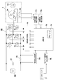
- FIG. 2 is a schematic block diagram of the impact tool 1 of this embodiment.
- a battery 90 composed of a secondary battery is used as a power source.
- the arithmetic unit 70 includes a microcomputer 71 and drives an inverter circuit 80 composed of a plurality of semiconductor switching elements Q1 to Q6.
- the motor 3 is a so-called inner rotor type, and has three position detection elements arranged at intervals of 60 ° so as to face the rotor 3a configured by embedding a magnet (permanent magnet) including a pair of N poles and S poles. 13 is provided.
- the stator 3b includes star-connected three-phase windings U, V, W.
- the calculation unit 70 is an example of the "control unit" of the present invention.
- the inverter circuit 80 is composed of six switching elements Q1 to Q6 such as FETs connected in a three-phase bridge format.
- a capacitor 77 for suppressing fluctuation at the time of rising current is provided in parallel with the battery 90 between the inverter circuit 80 and the battery 90.
- the microcomputer 71 drives and controls the switching elements Q1 to Q6 via the control signal output circuit 72.
- Each gate of the six switching elements Q1 to Q6 bridged is connected to the control signal output circuit 72, and each drain or source of the six switching elements Q1 to Q6 is a star-connected stator winding. Connected to U, V, W.
- the six switching elements Q1 to Q6 perform a switching operation by the switching element drive signal (drive signal of H4, H5, H6, etc.) input from the control signal output circuit 72, and are applied to the inverter circuit 80.
- the DC voltage of the battery 90 is set as three-phase (U-phase, V-phase and W-phase) voltages Vu, Vv and Vw, and power is supplied to the stator windings U, V and W.
- the switching element drive signals (3-phase signals) that drive each gate of the 6 switching elements Q1 to Q6, the three switching elements Q4, Q5, and Q6 on the negative power supply side are pulse width modulated signals (PWM signals) H4. , H5, H6, and the power to the motor 3 by changing the pulse width (duty ratio) of the PWM signal based on the detection signal of the operation amount (stroke) of the trigger lever 7a of the trigger switch 7 by the microcomputer 71.
- the supply amount is adjusted to control the start / stop and rotation speed of the motor 3.
- the calculation unit 70 includes a microcomputer 71, and is connected to a current detection circuit 75, a switch operation detection circuit 76, a rotation position detection circuit 73, and a rotation speed detection circuit 74.
- the microcomputer 71 that forms the core of the arithmetic unit 70 is a CPU for outputting a drive signal based on a processing program and data, and a ROM for storing programs and control data corresponding to the flowchart described later. It is configured with a built-in RAM for temporarily storing data, a timer, and the like.
- the current detection circuit 75 detects the current flowing through the motor 3 by measuring the voltage across the shunt resistor 78, and the detection output is input to the microcomputer 71.
- the switch operation detection circuit 76 detects whether or not the trigger lever 7a is pulled, and if it is pulled even a little, an on signal is output to the microcomputer 71.
- the rotation position detection circuit 73 is a circuit for detecting the relational positions between the armature windings U, V, and W of the rotor 3a and the stator 3b based on the output signals of the three position detection elements 13.
- the rotation speed detection circuit 74 is a circuit that detects the rotation speed of the motor based on the number of detection signals from the rotation position detection circuit 73 counted within a unit time.
- the control signal output circuit 72 supplies PWM signals H1 to H6 to the switching elements Q1 to Q6 based on the output from the microcomputer 71.
- the power supplied to each armature winding U, V, W is adjusted by controlling the pulse width of the PWM signal.
- FIG. 3 is a diagram for explaining a transition of a work situation in which a plurality of members are tightened by the impact tool 1 of the present embodiment.
- the bolt 61 is formed by a head portion 61a of a regular hexagonal column having an outer diameter and a shaft portion 61b extending downward from the bottom surface of the head portion 61a, and male threads 61c are formed in the entire axial direction of the shaft portion 61b. ..
- the nut 62 has a through hole formed in the center of a regular hexagonal prism, and a female screw is formed on the inner surface of the through hole.
- the steel plate portions 65 and 66 of the two steel frames are examples of the "plurality of members" of the present invention, and the bolt 61 and the nut 62 are examples of the "fastener” of the present invention.
- the objects to be tightened by the bolt 61 and the nut 62 are the steel plate portions 65 and 66 which are part of separate steel frames and have through holes for penetrating the bolt 61.
- iron plate portions 65 and 66 having different thicknesses are tightened, a washer 63 is interposed between the head portion 61a of the bolt 61 and the iron plate portion 65, and a washer 64 is interposed between the nut 62 and the iron plate portion 66. Is intervened.
- an example of rotating the lower nut 62 side using the impact tool 1 will be described.
- this state is referred to as a "close contact state", and is a state detected by the method described in this embodiment.
- a state in which a plurality of members such as the iron plate portions 65 and 66 are tightened by fasteners such as bolts 61 and nuts 62 and are in close contact with each other is an example of the "close contact state" of the present invention.
- the microcomputer 71 included in the calculation unit 70 of the impact tool 1 executes the tightening of the specified torque amount from the state where the “close contact state” is reached. For example, in the assembling work of a steel frame for a private house, tightening is performed with a specified torque of about 100 Nm. A predetermined tightening F (see FIG. 4 to be described later) is performed until the specified tightening completion state shown in FIG. 3 (E) is performed via the state. How to set the tightening F is preset by the manufacturer of the tightening tool.
- FIG. 4 is a graph showing the relationship between the passage of time, the peak value 82 of the current of the motor 3 and the moving average 83 of the peak value 82 of the current when the nut 62 is tightened to the tightening target shown in FIG. be.
- the microcomputer 71 of the arithmetic unit 70 uses the output of the current detection circuit 75 to set the current value in real time. To monitor.
- the waveform to be monitored is 82.
- the output of the current detection circuit 75 (current waveform 81 described later in FIG. 5) is not plotted as it is, but the peak value 82 of the detected current is plotted and the plot points are connected by a straight line. ..
- a method of detecting the peak value 82 of the current will be described with reference to FIG.
- FIG. 5 is an enlarged view of a part of the current waveform 81 of the motor 3, and is a waveform diagram of a signal input to the microcomputer 71 from the current detection circuit 75 shown in FIG.
- the motor 3 is driven by using the inverter circuit 80 as described with reference to FIG. 2 using the inner rotor type brushless DC motor as the drive source.
- PWM PulseWidthModulation
- the PWM control controls the motor 3 by changing the duty cycle (ratio of H and L of the pulse width) of the pulse width according to the magnitude of the input signal (DC voltage) with a constant cycle. be.
- the current waveform 81 moves up and down so as to undulate with a period of about 0.02 seconds.
- the repetitive striking operation by the impact mechanism 25 is configured to be repeated in a cycle of about 0.02 seconds.
- the fluctuation of the current waveform 81 with a period of about 0.02 seconds shown in FIG. 5 is caused by the repeated striking operation with the same period of about 0.02 seconds.
- the current values shown by the arrows 81a, 81b, and 81c are the peak values of the current of the current waveform 81 that fluctuates due to the repeated striking operation. Therefore, the microcomputer 71 takes out the current values shown by the arrows 81a, 81b, and 81c as the peak value 82 of the current caused by the repeated striking operation, and uses them for the determination process of the close contact state.
- the waveform of the peak value 82 of the current in FIG. 4 is obtained by plotting a large number of current values indicated by arrows 81a, 81b, and 81c in FIG. 5 and connecting the plots with a line.
- the spire-shaped current values other than the arrows 81a, 81b, and 81c are not generated due to the repeated striking operation and are not used as values for determining the close contact state.
- the integrated value of the current in the vicinity of the peak value of the current may be used, or the average value of the peak values of a plurality of adjacent currents may be used. Conceivable.
- the magnitudes of the current peaks 81a, 81b, 81c, and 82 generated by the repeated impact operation of the impact mechanism 25 are an example of the “current peak value” of the present invention.
- the peak value 82 of the current gradually increases as shown by the arrows (A) to (E) as the tightening by the impact tool 1 is performed.
- the moving average 83 of the peak value 82 of the current is obtained by calculating and plotting the moving average of the peak values 82 of the latest plurality of currents.
- the number of samples for calculating the moving average may be, for example, about 3 to 5.
- the inclination value of the moving average 83 which has risen almost linearly until then, becomes large.
- the state of the arrow (A) is a state in which the rotation of the nut 62 to be tightened after the "seating state” is hindered, and the current value flowing through the motor 3 suddenly rises.
- the iron plate portions 65 and 66 shown in FIG. 3 move in the approaching direction due to the tightening of the bolt 61 and the nut 62.
- the moving average 83 indicated by the arrow (C) and the arrow (4) is the moving average of the peak values 82 of the three most recent currents (1) to (3).
- the present invention as the determination of the adhesion state of the clamping object, using a threshold current I S of the peak value of the current flowing in the motor (the peak value of the current 82), the peak value of the current itself, or, the peak current If the function value (moving average 83) exceeds the threshold value I S, it is determined that a plurality of clamping object member (iron plate 65, 66) becomes close contact.
- the first control mode is changed to the second.
- the necessary conditions for determining that the first switching condition is satisfied are that the peak value of the current tends to increase and the rate of change of the peak value of the current. It is conceivable that the increase is a necessary condition.
- FIG. 6 is a graph showing the change amount 84 of the moving average 83 of the peak value 82 of the current shown in FIG. 4, and the calculated change amount of the moving average 83, that is, the calculated moving average 83 (see FIG. 4). It is a plot of the difference between the moving average and the moving average 83 calculated immediately before that. The horizontal axis is the tightening time, and the vertical axis is the amount of change in the moving average value of the peak value 82 of the current.
- +0.2 means that the moving average has increased by 0.2 (A) from the moving average 83 calculated immediately before
- -0.2 means that the moving average has increased from the moving average 83 calculated immediately before. It shows that it decreased by 0.2 (A).
- the increase determination threshold value I 1 is set to 0.2 A, and the time point of the arrow (4) in which the change amount 84 increases the increase determination threshold value I 1 three times in a row is determined to be “close contact state”. .. It should be noted that not only the point at which the amount of change in the moving average 83 appears significantly before and after the close contact state is determined as the "close contact state", but also the "close contact” state may be determined by monitoring the inclination of the moving average 83.
- the moment of inertia of the rotating system by the motor 3, the spindle 26, and the hammer 30 is configured to be lower than before.
- the moment of inertia of the motor 3 is affected by the square of the reduction gear ratio of the reduction mechanism 20. That is, when the gear ratio is lowered, the moment of inertia is lowered.
- the torque of the motor 3 and the magnitude of the moment of inertia of the rotating system basically affect the moment of inertia. If it is large, the decrease in the rotation speed is small, so that the change in the current value of the motor 3 does not become large.
- the gear ratio of the reduction mechanism 20 is set to be lower than before.
- the deceleration is performed at a gear ratio of 8.286, but in this embodiment, it is set to about 5.0 or less.
- an inner rotor type brushless DC motor as the motor 3 instead of a brushed DC motor. Since the inner rotor type brushless DC motor has a small moment of inertia of the rotor, the current value is likely to change when the object to be tightened is in close contact, and the detection accuracy of the close contact state using the peak current as in this embodiment is high. ..
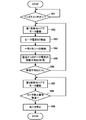
- the control procedure shown in FIG. 7 can be realized by software by executing a computer program in the arithmetic unit 70 having the microcomputer (microprocessor) 71.
- the microcomputer 71 detects whether or not the trigger lever 7a is pulled by the operator and the trigger switch 7 is turned on, and if it is pulled, the process proceeds to step 102 (step 101). If the trigger switch 7 is not turned on, the microcomputer 71 waits until it is turned on.
- step 101 when the trigger lever 7a is pulled even a little and the trigger switch 7 is turned on, the microcomputer 71 rotates and drives the motor 3 according to the pulling amount of the trigger lever 7a.
- This rotary drive is referred to as a "first control mode" in order to distinguish it from the rotary drive of step 107 described later.
- the calculation unit 70 continuously rotates the motor 3 by, for example, constant speed control, while the trigger switch 7 is ON, until a predetermined condition is satisfied. While the motor 3 is being driven in the first control mode, the motor 3 detects peak currents (1), (2), and (3) in one cycle of PWM control by the method described with reference to FIG.
- step 106 if the moving average 83 is equal to or less than the threshold current I S returns to step 102, if it exceeds the threshold current I S, the microcomputer 71 of the driving mode of the motor 3 is switched to "second control mode" motor 3 is driven (step 107).
- microcomputer 71 is the moving average 83 shows an example of determining a "first switching condition is satisfied" that exceeds the threshold current I S shown in FIG. 4, the first switching condition is satisfied
- Other conditions for determining that the current was achieved were (1) the peak value of the current was equal to or higher than the predetermined value, (2) the moving average value of the peak value of the current was greater than or equal to the predetermined value, and (3).
- the slope of the moving average value of the peak value of the current exceeds a predetermined value, (4) any one of (1) to (3) occurs multiple times, and (5) from (1) above. It may be configured so that any one of (3) occurs consecutively multiple times as a necessary condition.
- the control of continuously rotating the motor 3 until a predetermined condition is satisfied while the trigger switch 7 is ON is an example of the "first control mode" of the present invention.
- the "second control mode" in step 107 is the tightening control from reaching the close contact state of FIG. 3 (C) to (E), in order to accurately tighten the tightening target with a specified torque value.
- Rotation control Various settings can be made as to how the rotation control from FIG. 3C to FIG. 3E is performed.
- a machine learning device (not shown) configured to generate a determination algorithm for determining the tightening state of the fastener to be fastened by the impact tool 1 is used to learn the adhesion condition, and the algorithm generated by the machine learning device is used as a microcomputer. It is good to execute at 71.
- the machine learning device (not shown) has an input unit and an input unit configured to input tightening data in which physical information related to the load applied to the motor 3 of the impact tool 1 and the tightening state of the fastener are associated with each other. It has a generator configured to perform machine learning by a genetic algorithm and generate the determination algorithm for determining the tightening state based on the tightening data input in.
- the control from the satisfaction of a predetermined condition to the completion of tightening is an example of the "second control mode" of the present invention.
- the input values for inputting the tightening data to the machine learning device are the current of the motor 3, the rotation speed, and the voltage of the battery 90, and by performing machine learning using a genetic algorithm, the optimum "first" for each tightening target.
- Detailed control in “2 control mode” can be derived.
- the detailed control in this "second control mode” is performed by the manufacturer who develops the impact tool 1 by using a machine learning device at the time of development, and software and parameters for deriving the results are preliminarily sent to the calculation unit 70 of the impact tool 1. You can store it.
- step 107 the motor 3 is driven until the second switching condition different from the first switching condition is satisfied, and when the second switching condition is satisfied, the rotation of the motor 3 is stopped. (Step 109).
- the rotation of the motor 3 after close contact is controlled, but the microcomputer 71 satisfies the second switching condition.
- the repeated striking operation was executed a predetermined number of times after the first switching condition was satisfied, or the repetitive striking operation was executed for a predetermined time after the first switching condition was satisfied.
- One of the requirements is required.
- step 109 it is not limited to (a) stopping the rotation of the motor 3, but (b) reducing the rotation speed of the motor 3 or (c) the first switching condition. Will execute the above (a) or (b) when a different second switching condition is satisfied, or (d) notify the operator of the completion of tightening by a notification unit that emits a sound or light. It may be configured.
Landscapes
- Engineering & Computer Science (AREA)
- Mechanical Engineering (AREA)
- Details Of Spanners, Wrenches, And Screw Drivers And Accessories (AREA)
- Portable Power Tools In General (AREA)
Priority Applications (2)
| Application Number | Priority Date | Filing Date | Title |
|---|---|---|---|
| DE112021003035.3T DE112021003035T5 (de) | 2020-05-29 | 2021-04-27 | Festziehwerkzeug |
| JP2022527607A JP7400966B2 (ja) | 2020-05-29 | 2021-04-27 | 締め付け工具 |
Applications Claiming Priority (2)
| Application Number | Priority Date | Filing Date | Title |
|---|---|---|---|
| JP2020-094091 | 2020-05-29 | ||
| JP2020094091 | 2020-05-29 |
Publications (1)
| Publication Number | Publication Date |
|---|---|
| WO2021241111A1 true WO2021241111A1 (ja) | 2021-12-02 |
Family
ID=78745306
Family Applications (1)
| Application Number | Title | Priority Date | Filing Date |
|---|---|---|---|
| PCT/JP2021/016740 Ceased WO2021241111A1 (ja) | 2020-05-29 | 2021-04-27 | 締め付け工具 |
Country Status (3)
| Country | Link |
|---|---|
| JP (1) | JP7400966B2 (https=) |
| DE (1) | DE112021003035T5 (https=) |
| WO (1) | WO2021241111A1 (https=) |
Cited By (3)
| Publication number | Priority date | Publication date | Assignee | Title |
|---|---|---|---|---|
| WO2023166922A1 (ja) * | 2022-03-04 | 2023-09-07 | 工機ホールディングス株式会社 | 作業機 |
| JP2023178147A (ja) * | 2022-06-04 | 2023-12-14 | 了 久保田 | ねじ締め装置 |
| US12489382B2 (en) | 2021-12-15 | 2025-12-02 | Milwaukee Electric Tool Corporation | Adaptive trigger mapping |
Citations (3)
| Publication number | Priority date | Publication date | Assignee | Title |
|---|---|---|---|---|
| JPH07308866A (ja) * | 1994-05-13 | 1995-11-28 | Nissan Motor Co Ltd | 締付け軸力の測定装置とそれを用いたインパクト式ねじ締め装置 |
| JPH1071576A (ja) * | 1996-06-20 | 1998-03-17 | Nissan Motor Co Ltd | インパクト式ねじ締め方法と装置 |
| JP2018158417A (ja) * | 2017-03-23 | 2018-10-11 | 株式会社マキタ | インパクト締結工具 |
Family Cites Families (4)
| Publication number | Priority date | Publication date | Assignee | Title |
|---|---|---|---|---|
| JP3552249B2 (ja) * | 1993-07-09 | 2004-08-11 | ソニー株式会社 | 画像および音声信号処理方法とその装置 |
| JP5115904B2 (ja) | 2007-09-21 | 2013-01-09 | 日立工機株式会社 | インパクト工具 |
| JP5527569B2 (ja) | 2007-09-21 | 2014-06-18 | 日立工機株式会社 | インパクト工具 |
| JP6024446B2 (ja) | 2012-12-22 | 2016-11-16 | 日立工機株式会社 | インパクト工具 |
-
2021
- 2021-04-27 WO PCT/JP2021/016740 patent/WO2021241111A1/ja not_active Ceased
- 2021-04-27 DE DE112021003035.3T patent/DE112021003035T5/de active Pending
- 2021-04-27 JP JP2022527607A patent/JP7400966B2/ja active Active
Patent Citations (3)
| Publication number | Priority date | Publication date | Assignee | Title |
|---|---|---|---|---|
| JPH07308866A (ja) * | 1994-05-13 | 1995-11-28 | Nissan Motor Co Ltd | 締付け軸力の測定装置とそれを用いたインパクト式ねじ締め装置 |
| JPH1071576A (ja) * | 1996-06-20 | 1998-03-17 | Nissan Motor Co Ltd | インパクト式ねじ締め方法と装置 |
| JP2018158417A (ja) * | 2017-03-23 | 2018-10-11 | 株式会社マキタ | インパクト締結工具 |
Cited By (5)
| Publication number | Priority date | Publication date | Assignee | Title |
|---|---|---|---|---|
| US12489382B2 (en) | 2021-12-15 | 2025-12-02 | Milwaukee Electric Tool Corporation | Adaptive trigger mapping |
| WO2023166922A1 (ja) * | 2022-03-04 | 2023-09-07 | 工機ホールディングス株式会社 | 作業機 |
| JPWO2023166922A1 (https=) * | 2022-03-04 | 2023-09-07 | ||
| JP2023178147A (ja) * | 2022-06-04 | 2023-12-14 | 了 久保田 | ねじ締め装置 |
| JP7579824B2 (ja) | 2022-06-04 | 2024-11-08 | 了 久保田 | ねじ締め装置 |
Also Published As
| Publication number | Publication date |
|---|---|
| DE112021003035T5 (de) | 2023-03-16 |
| JP7400966B2 (ja) | 2023-12-19 |
| JPWO2021241111A1 (https=) | 2021-12-02 |
Similar Documents
| Publication | Publication Date | Title |
|---|---|---|
| CN102770241B (zh) | 冲击工具 | |
| JP5483089B2 (ja) | インパクト工具 | |
| US8678106B2 (en) | Rotary impact tool | |
| JP5935983B2 (ja) | 電動工具 | |
| US20160107297A1 (en) | Electric power tool | |
| JP6032289B2 (ja) | インパクト工具 | |
| JP5896143B2 (ja) | 電動工具 | |
| JP6107385B2 (ja) | 電動工具 | |
| US20120234566A1 (en) | Impact tool | |
| US20150231771A1 (en) | Power Tool | |
| US20140374130A1 (en) | Impact Tool | |
| WO2021241111A1 (ja) | 締め付け工具 | |
| US20170070168A1 (en) | Electric tool | |
| JP5621980B2 (ja) | インパクト工具 | |
| JP2013022681A (ja) | 電動工具 | |
| JP2011031314A (ja) | インパクト工具 | |
| WO2014162862A1 (ja) | 電動工具 | |
| JP6984742B2 (ja) | 電動工具 | |
| JP2014140930A (ja) | 電動工具 | |
| US20250025990A1 (en) | Impact tool | |
| JP5556218B2 (ja) | インパクト工具 | |
| JP5648970B2 (ja) | インパクト工具 | |
| JP5440765B2 (ja) | インパクト工具 | |
| JP5447025B2 (ja) | インパクト工具 | |
| JP5322035B2 (ja) | インパクト工具 |
Legal Events
| Date | Code | Title | Description |
|---|---|---|---|
| 121 | Ep: the epo has been informed by wipo that ep was designated in this application |
Ref document number: 21813405 Country of ref document: EP Kind code of ref document: A1 |
|
| ENP | Entry into the national phase |
Ref document number: 2022527607 Country of ref document: JP Kind code of ref document: A |
|
| 122 | Ep: pct application non-entry in european phase |
Ref document number: 21813405 Country of ref document: EP Kind code of ref document: A1 |