WO2021240870A1 - 電磁機器及び電磁機器を用いた航空機 - Google Patents
電磁機器及び電磁機器を用いた航空機 Download PDFInfo
- Publication number
- WO2021240870A1 WO2021240870A1 PCT/JP2021/002029 JP2021002029W WO2021240870A1 WO 2021240870 A1 WO2021240870 A1 WO 2021240870A1 JP 2021002029 W JP2021002029 W JP 2021002029W WO 2021240870 A1 WO2021240870 A1 WO 2021240870A1
- Authority
- WO
- WIPO (PCT)
- Prior art keywords
- rotor
- stator core
- magnet
- main body
- electromagnetic device
- Prior art date
- Legal status (The legal status is an assumption and is not a legal conclusion. Google has not performed a legal analysis and makes no representation as to the accuracy of the status listed.)
- Ceased
Links
Images


Classifications
-
- H—ELECTRICITY
- H02—GENERATION; CONVERSION OR DISTRIBUTION OF ELECTRIC POWER
- H02K—DYNAMO-ELECTRIC MACHINES
- H02K16/00—Machines with more than one rotor or stator
- H02K16/02—Machines with one stator and two or more rotors
-
- H—ELECTRICITY
- H02—GENERATION; CONVERSION OR DISTRIBUTION OF ELECTRIC POWER
- H02K—DYNAMO-ELECTRIC MACHINES
- H02K1/00—Details of the magnetic circuit
- H02K1/06—Details of the magnetic circuit characterised by the shape, form or construction
- H02K1/12—Stationary parts of the magnetic circuit
-
- H—ELECTRICITY
- H02—GENERATION; CONVERSION OR DISTRIBUTION OF ELECTRIC POWER
- H02K—DYNAMO-ELECTRIC MACHINES
- H02K1/00—Details of the magnetic circuit
- H02K1/06—Details of the magnetic circuit characterised by the shape, form or construction
- H02K1/12—Stationary parts of the magnetic circuit
- H02K1/14—Stator cores with salient poles
-
- H—ELECTRICITY
- H02—GENERATION; CONVERSION OR DISTRIBUTION OF ELECTRIC POWER
- H02K—DYNAMO-ELECTRIC MACHINES
- H02K1/00—Details of the magnetic circuit
- H02K1/06—Details of the magnetic circuit characterised by the shape, form or construction
- H02K1/12—Stationary parts of the magnetic circuit
- H02K1/18—Means for mounting or fastening magnetic stationary parts on to, or to, the stator structures
-
- H—ELECTRICITY
- H02—GENERATION; CONVERSION OR DISTRIBUTION OF ELECTRIC POWER
- H02K—DYNAMO-ELECTRIC MACHINES
- H02K1/00—Details of the magnetic circuit
- H02K1/06—Details of the magnetic circuit characterised by the shape, form or construction
- H02K1/22—Rotating parts of the magnetic circuit
-
- H—ELECTRICITY
- H02—GENERATION; CONVERSION OR DISTRIBUTION OF ELECTRIC POWER
- H02K—DYNAMO-ELECTRIC MACHINES
- H02K21/00—Synchronous motors having permanent magnets; Synchronous generators having permanent magnets
- H02K21/12—Synchronous motors having permanent magnets; Synchronous generators having permanent magnets with stationary armatures and rotating magnets
-
- H—ELECTRICITY
- H02—GENERATION; CONVERSION OR DISTRIBUTION OF ELECTRIC POWER
- H02K—DYNAMO-ELECTRIC MACHINES
- H02K7/00—Arrangements for handling mechanical energy structurally associated with dynamo-electric machines, e.g. structural association with mechanical driving motors or auxiliary dynamo-electric machines
- H02K7/003—Couplings; Details of shafts
-
- B—PERFORMING OPERATIONS; TRANSPORTING
- B64—AIRCRAFT; AVIATION; COSMONAUTICS
- B64D—EQUIPMENT FOR FITTING IN OR TO AIRCRAFT; FLIGHT SUITS; PARACHUTES; ARRANGEMENT OR MOUNTING OF POWER PLANTS OR PROPULSION TRANSMISSIONS IN AIRCRAFT
- B64D27/00—Arrangement or mounting of power plants in aircraft; Aircraft characterised by the type or position of power plants
- B64D27/02—Aircraft characterised by the type or position of power plants
- B64D27/30—Aircraft characterised by electric power plants
- B64D27/34—All-electric aircraft
-
- H—ELECTRICITY
- H02—GENERATION; CONVERSION OR DISTRIBUTION OF ELECTRIC POWER
- H02K—DYNAMO-ELECTRIC MACHINES
- H02K1/00—Details of the magnetic circuit
- H02K1/06—Details of the magnetic circuit characterised by the shape, form or construction
- H02K1/12—Stationary parts of the magnetic circuit
- H02K1/18—Means for mounting or fastening magnetic stationary parts on to, or to, the stator structures
- H02K1/185—Means for mounting or fastening magnetic stationary parts on to, or to, the stator structures to outer stators
-
- H—ELECTRICITY
- H02—GENERATION; CONVERSION OR DISTRIBUTION OF ELECTRIC POWER
- H02K—DYNAMO-ELECTRIC MACHINES
- H02K1/00—Details of the magnetic circuit
- H02K1/06—Details of the magnetic circuit characterised by the shape, form or construction
- H02K1/12—Stationary parts of the magnetic circuit
- H02K1/18—Means for mounting or fastening magnetic stationary parts on to, or to, the stator structures
- H02K1/187—Means for mounting or fastening magnetic stationary parts on to, or to, the stator structures to inner stators
-
- H—ELECTRICITY
- H02—GENERATION; CONVERSION OR DISTRIBUTION OF ELECTRIC POWER
- H02K—DYNAMO-ELECTRIC MACHINES
- H02K21/00—Synchronous motors having permanent magnets; Synchronous generators having permanent magnets
- H02K21/12—Synchronous motors having permanent magnets; Synchronous generators having permanent magnets with stationary armatures and rotating magnets
- H02K21/14—Synchronous motors having permanent magnets; Synchronous generators having permanent magnets with stationary armatures and rotating magnets with magnets rotating within the armatures
- H02K21/16—Synchronous motors having permanent magnets; Synchronous generators having permanent magnets with stationary armatures and rotating magnets with magnets rotating within the armatures having annular armature cores with salient poles
-
- H—ELECTRICITY
- H02—GENERATION; CONVERSION OR DISTRIBUTION OF ELECTRIC POWER
- H02K—DYNAMO-ELECTRIC MACHINES
- H02K21/00—Synchronous motors having permanent magnets; Synchronous generators having permanent magnets
- H02K21/12—Synchronous motors having permanent magnets; Synchronous generators having permanent magnets with stationary armatures and rotating magnets
- H02K21/22—Synchronous motors having permanent magnets; Synchronous generators having permanent magnets with stationary armatures and rotating magnets with magnets rotating around the armatures, e.g. flywheel magnetos
- H02K21/222—Flywheel magnetos
-
- H—ELECTRICITY
- H02—GENERATION; CONVERSION OR DISTRIBUTION OF ELECTRIC POWER
- H02K—DYNAMO-ELECTRIC MACHINES
- H02K2213/00—Specific aspects, not otherwise provided for and not covered by codes H02K2201/00 - H02K2211/00
- H02K2213/03—Machines characterised by numerical values, ranges, mathematical expressions or similar information
Definitions
- This application relates to electromagnetic equipment and aircraft using electromagnetic equipment.
- stator core of a rotary electric machine which is an electromagnetic device surrounded by two opposing movable parts
- thin plates are laminated in a direction parallel to the two surfaces facing the movable part, which is a rotor, and perpendicular to the movable direction of the movable part.
- a stator core is disclosed in which a stator core is formed by providing a hole penetrating in the stacking direction and fitting a holding member into the hole (for example, Patent Document 1).
- a stator core is formed by laminating thin plates in a direction parallel to the two opposing movable parts and in a direction substantially parallel to the movable part of the movable part, and the stator core is parallel to the two surfaces facing the movable part and the movable part.
- a rotary electric machine that holds a stator core by providing bolt holes for holding between layers in a direction perpendicular to the movable direction and fastening them with bolts is disclosed (for example, Patent Document 2).
- Patent Document 1 since the electromagnetic force accompanying the operation of the rotary electric machine acts in a direction of shearing between the laminated layers of the stator core, a hole penetrating in the layering direction is provided to hold the stator core, and the holding member is fitted into the hole. ing. Therefore, since the holding member hits the magnetic path of the stator core, there is a risk that the size of the device will be increased and the efficiency will be reduced.
- Patent Document 2 since it is necessary to apply a sandwiching force in the stacking direction to hold the stator core, the magnetic characteristics of the stator core deteriorate. Further, in another example of Patent Document 2, since the stator core is pressed by the fitting portion, the magnetic characteristics are deteriorated.
- the present application discloses a technique for solving the above-mentioned problems, an electromagnetic device that holds a stator core without deteriorating the magnetic characteristics without increasing the size of the device, and an aircraft using the electromagnetic device.
- the purpose is to provide.
- the electromagnetic devices disclosed in the present application include two moving parts that move in parallel or antiparallel to each other.
- An electromagnetic device comprising a stator core having two surfaces arranged facing each of the two movable portions, wherein at least a part of the stator core is laminated with thin plates in the movable direction of the movable portion. It is held by applying tensile stress in a direction parallel to the two surfaces facing the two movable portions and perpendicular to the movable direction of the movable portions.
- the stator core is held by applying tensile stress, it is possible to hold the stator core without deteriorating the magnetic characteristics of the stator core without increasing the size of the device.
- FIG. 1 is a cross-sectional view taken along the rotation axis of the rotary electric machine according to the first embodiment, and is a partially enlarged view of FIG. It is a partial sectional view perpendicular to the rotation axis of the rotary electric machine which concerns on Embodiment 1.
- FIG. It is a figure which shows the structure of the stator core of the rotary electric machine which concerns on Embodiment 1.
- FIG. It is sectional drawing which is perpendicular to the rotation axis of the rotary electric machine which concerns on Embodiment 2.
- FIG. It is sectional drawing along the rotation axis of the rotary electric machine which concerns on Embodiment 3.
- FIG. It is a partial sectional view perpendicular to the rotation axis of the rotary electric machine which concerns on Embodiment 3.
- FIG. It is a partial perspective view which shows the structure of the stator of the rotary electric machine which concerns on Embodiment 4.
- FIG. It is a partial perspective view which shows the structure of the stator core of the rotary electric machine which concerns on Embodiment 4.
- FIG. It is a partial perspective view which shows the structure of the stator core of the rotary electric machine which concerns on Embodiment 4, and is a partially enlarged view of FIG.
- FIG. It is a perspective view which shows the assembly method of the stator core of the rotary electric machine which concerns on Embodiment 4.
- FIG. 5 is a partial cross-sectional view perpendicular to the rotation axis of the rotary electric machine according to the fifth embodiment. It is sectional drawing along the rotation axis of the rotary electric machine which concerns on Embodiment 6.
- FIG. 6 is a cross-sectional view perpendicular to the rotation axis of the rotary electric machine according to the sixth embodiment, showing the structure of the stator. It is sectional drawing along the rotation axis of the magnetic gear which concerns on Embodiment 7.
- FIG. 5 is a cross-sectional view perpendicular to the rotation axis of the magnetic gear according to the seventh embodiment. It is sectional drawing along the movable shaft for showing the structure of the linear motor which concerns on Embodiment 8. It is a schematic diagram which shows the aircraft using the electromagnetic device which concerns on Embodiment 9. It is another schematic diagram which shows another aircraft using the electromagnetic device which concerns on Embodiment 9. FIG.
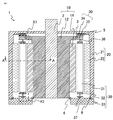
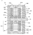
- FIG. 1 is a cross-sectional view taken along a rotation axis showing the structure of the rotary electric machine according to the first embodiment.
- the rotary electric machine 1 includes two rotors, an inner rotor 10, an outer rotor 20, and a stator 30 sandwiched between the two rotors in the radial direction, and is configured as a double rotor type radial gap motor.
- the inner rotor 10 includes a shaft 2, a boss 12 press-fitted and fixed to the shaft 2, and a permanent magnet 14 adhesively fixed to the outer diameter side of the boss 12.
- the outer rotor 20 includes an outer shaft 21 fixed to the shaft 2 and a permanent magnet 22 adhesively fixed to the inner diameter side of the outer shaft 21.
- the stator core 31 is arranged between the load side holding member 35 attached to the load side base 34 and the unload side base 33 in the axial direction, and the stator coil 32 is wound around the stator core 31.
- stator 30 is arranged between the inner rotor 10 and the outer rotor 20, but the inner bearing 3 on the load side, the outer bearing 5 on the load side, the inner bearing 4 on the non-load side, and the outer bearing 6 on the non-load side provide an inner bearing 30.
- the rotor 10 and the outer rotor 20 are rotatably held.
- FIG. 2 is an enlarged view of regions X1 and X2 surrounded by a broken line in FIG.
- the stator core 31 has both ends in the axial direction near the center in the radial direction extending in the axial direction and projecting from the wound portion of the stator coil 32, and one of the tip portions 31c on the load side is bolted to the load side holding member 35. It is fixed at 38, and the tip portion 31d on the other fixed side is fixed so as to be hooked on the T-shaped groove portion 33a provided on the counterload side base 33.
- stator core 31 is stretched in the axial direction and tensile stress is applied.
- FIG. 3 is a cross-sectional view perpendicular to the rotation axis of the rotary electric machine 1, and is a partial cross-sectional view in the direction of AA in FIG.
- the rotary electric machine 1 is composed of 48 poles and 72 slots of centralized winding.
- the stator core 31 is formed by laminating thin steel plates long in the axial direction in the substantially circumferential direction. Both the inner rotor 10 and the outer rotor 20 rotate counterclockwise in the figure at the same angular velocity. That is, the inner rotor 10 and the outer rotor 20 are movable portions.
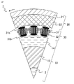
- FIG. 4 is a diagram showing the structure of the stator core 31.
- the stator core 31 is axially long with a tip portion 31c having an axial end protruding from the main body 31a and having a hole for bolt fastening, and a tip portion 31d having a T-shaped tip protruding from the other end in the axial direction. It is made of a thin steel plate, and both side portions 31b in the axial direction are bent as shown by the arrows in FIG. 4A. Then, as shown in FIG. 3, the inner rotor 10 and the side portions 31b of the stator core 31 facing the outer rotor 20 side are laminated in a state of being bent to the rotation direction lagging side at an angle shallower than 90 °. Has been done.
- the thin steel plate of the stator core 31 is an electromagnetic steel plate manufactured by rolling, and the rolling direction is the radial direction of the stator core, the direction connecting the side portions 31b, and arranged so as to face the inner rotor 10 and the outer rotor. Has been done. Further, as shown in FIGS. 1 and 2, the stator core 31 is bolted in a state where the tip portion 31d is fixed to the T-shaped groove portion 33a provided on the counterload side base 33 and the stator core 31 is pulled in the axial direction. The tip portion 31c is fixed and attached by 38.
- stator core 31 is fixed by applying tensile stress, deterioration of magnetic characteristics due to compressive stress is eliminated, and high efficiency can be achieved. Further, since the central portion in the radial direction of the stator core 31 is fixed, it is easy to evenly apply tensile stress to the stator core 31, and it is easy to improve efficiency. Further, since the tip portions 31c and 31d of the stator core 31 are thinner than the main body portion 31a, their axial cross-sectional area is smaller, and the stator core 31 is fixed at a position protruding from the coil around which the stator coil 32 is wound. The effect on the magnetic path is also small.
- the tip portions 31c and 31d are thinner than the main body portion 31a of the stator core 31, so that the axial cross-sectional area thereof is large. It is small and has a small effect on the magnetic path.
- the load-side holding member 35 and the non-load-side base 33 are made of a non-magnetic material, a closed magnetic path to the stator core 31 in each circumferential direction is not formed, so that the influence on the magnetic path can be eliminated.
- stator core 31 since the axial side portion 31b of the stator core 31 is bent to the side delayed in the rotation direction, the magnetic flux generated by the movable inner rotor 10 and outer rotor 20 can be easily collected in the stator core 31.
- the tips on both sides in the axial direction show a structure in which both the side portions 31b on the inner rotor 10 side and the outer rotor 20 side are bent toward the delayed side in the rotational direction, as shown in FIGS. 4B and 4C.
- the same effect can be obtained by bending only one of the side portions 31b.
- both side portions 31b in the axial direction of the stator core 31 are bent at the same angle, but the bending angle may be gradually increased toward the radial delay side. By doing so, it becomes easier to collect a larger amount of magnetic flux, so that the torque of the rotary electric machine 1 can be increased.
- the stator 30 is arranged between the inner rotor 10 and the outer rotor 20 that are movable around the shaft 2, and the thin plate of the stator 30 is in the rotation direction. Since the stator core 31 is laminated in the above and is held by applying tensile stress in the axial direction, it is possible to hold the stator core 31 without deteriorating the magnetic characteristics. This makes it possible to increase the efficiency and torque of the rotary electric machine.
- FIG. 5 is a partial cross-sectional view perpendicular to the rotation axis of the rotary electric machine 1 according to the second embodiment.
- the stator core 31 of the rotary electric machine 1 is configured by laminating thin steel plates long in the axial direction in a substantially circumferential direction, that is, in a rotational direction. Both the inner rotor 10 and the outer rotor 20 rotate counterclockwise in the figure at the same angular velocity.
- the inner rotor 10 and the side portion 31b facing the outer rotor 20 side, which are the axial ends of the stator core 31, are configured to bend the surface of the thin steel plate at an angle shallower than 90 °. It is bent so that the bending angle gradually increases in the range of an angle shallower than 90 ° toward the radial lag side and the leading side, respectively, on the lagging side and the leading side in the rotational direction. There is a gap between the bent thin steel plates, and the gap is filled with resin. Other configurations are the same as those in the first embodiment.
- the same effect as that of the first embodiment is obtained. Further, since the side portion 31b of the stator core 31 is bent on both the radial lag side and the advancing side in the rotation direction, it is possible to achieve high torque of the rotary electric machine regardless of the direction of rotation. Become.
- FIG. 6 is a cross-sectional view taken along a rotation axis showing the structure of the rotary electric machine 1 according to the third embodiment.
- the stator core 31 has both inner rotor 10 and outer rotor 20 side portions extending in the axial direction and protruding from the main body portion at both ends in the axial direction, and the tip portions 31c and 31d thereof are on the load side.
- the natural length between both ends of the stator core 31 is the fixed side of the groove portion of the counterload side base 33 to which the L-shapes of the tip portions 31c and 31d at both ends of the stator core 31 are fixed.
- the length is shorter than the length of the holding surface 37 and the load-side holding surface 36 of the L-shaped groove provided on the outer side of the load-side holding member 35. Therefore, the L-shape of the tip portion 31d on one end side in the axial direction of the stator core 31 is fixed so as to be hooked on the L-shaped groove portion provided in the counterload side base 33, and is fixed to the other end side in the axial direction of the stator core 31.
- the L-shape of the tip portion 31c is fitted and held in the groove portion of the load-side holding member 35, and tensile stress is applied.
- the above-mentioned stator core 31 has a smaller axial cross-sectional area at both tip portions 31c and 31d than the main body portion around which the stator coil 32 is wound, and is fixed at a position extending from the main body portion. Similar to the first form, the influence on the magnetic path is small.
- FIG. 7 is a cross-sectional view perpendicular to the rotation axis of the rotary electric machine 1, and is a partial cross-sectional view in the direction of line BB in FIG.
- the stator core 31 is configured by laminating thin steel plates long in the axial direction in the substantially circumferential direction and the rotational direction. Both the inner rotor 10 and the outer rotor 20 rotate counterclockwise at the same angular velocity in the figure, and both sides of the inner rotor 10 and the outer rotor 20 side, which are both sides of the stator core 31 in the axial direction, are bent. It is on the same surface as the main body portion that is the winding portion of the stator core 31. Other structures are the same as those in the first embodiment.
- the stator 30 is arranged between the inner rotor 10 and the outer rotor 20 that are movable around the shaft 2, and the stator 30 has a stator core 31 in which thin plates are laminated in the rotational direction, and exerts tensile stress in the axial direction. Since it is hung and held, it is possible to hold the stator core 31 without deteriorating the magnetic characteristics. This makes it possible to increase the efficiency and torque of the rotary electric machine.
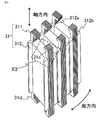
- FIG. 8 is a perspective view showing a part of the structure of the stator 30 of the rotary electric machine according to the fourth embodiment
- FIG. 9 is a perspective view showing the structure of the stator core 31
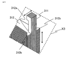
- FIG. 10 is a partially enlarged view of the broken line region X3 of FIG. It is a figure.
- the stator core 31 is configured by laminating thin steel plates long in the axial direction in the substantially circumferential direction and the rotational direction.
- the stator core 31 of the third embodiment has both inner rotor 10 and outer rotor 20 side portions extending in the axial direction and protruding from the main body portion at both ends in the axial direction, and the tip portion 31c thereof.
- the load side has an L-shaped inwardly bent structure
- the tip portion 31d has an L-shaped outwardly bent structure on the unloaded side.
- the stator core 31 of the fourth embodiment is composed of a side portion 311 facing the inner rotor 10 and the outer rotor 20, respectively, and a holding portion 312 holding both side portions 311 and winding the stator coil 32. The point is different.
- both side portions 311 of the stator core 31 are configured by laminating thin electromagnetic steel plates that are long in the axial direction in the substantially circumferential direction and the rotational direction.
- the holding portion 312 of the stator core 31 is configured by laminating an electromagnetic steel sheet having a predetermined shape in the axial direction at a height facing the permanent magnets 14 and 22 of the inner rotor 10 and the outer rotor 20, respectively.
- the holding portion 312 has a substantially rectangular shape, but a notch portion 312a is provided in the central portion on the inner peripheral side on the inner rotor side and the outer peripheral side on the outer rotor side, and both side portions 311 are inserted and held. Will be done.
- the flange portion 312b may be provided in the circumferential direction of the notch portion 312a as shown in the figure. Both side portions 311 of the stator core 31 are held in close contact with the holding portion 312 so that the magnetic flux in the direction orthogonal to the rotation axis flows seamlessly. Both side portions 311 extend from the holding portion 312 on both sides in the axial direction and have tip portions 31c and 31d bent in an L shape.
- the stator core 31 of the fourth embodiment which has both side portions 311 laminated in the circumferential direction and the holding portion 312 laminated in the axial direction, is also held by applying tensile stress in the axial direction as in the third embodiment. Will be done. That is, according to FIG. 6 of the third embodiment, the natural length of both side portions 311 of the stator core 31 is a counterload side base to which the L-shape of the tip of both side portions 311 of the stator core 31 is fixed. The length is shorter than the length of the fixed-side holding surface 37 of the groove of 33 and the load-side holding surface 36 of the L-shaped groove provided on the outer side of the load-side holding member 35.
- FIG. 9 shows a structure in which the L-shapes at both ends of both side portions 311 in the axial direction are bent inward so as to face the holding portion 312 side, but the structure is fixed as shown in FIG. On the side, the structure may be bent outward in an L shape.
- a part of the stator core 31 is formed by laminating thin electromagnetic steel plates long in the axial direction in the substantially circumferential direction and the rotational direction, and the tensile stress is generated. It is a structure that is hung and held, and it is possible to suppress deterioration of magnetic characteristics due to compressive stress and improve efficiency.
- the stator core 31 is configured by laminating thin steel plates long in the axial direction in the substantially circumferential direction and the rotational direction, but in the fourth embodiment, the side portion 311 is formed from the first embodiment.
- a thin steel plate that is long in the axial direction as in No. 3 is laminated on both the inner peripheral side and the outer peripheral side in the substantially circumferential direction and the rotational direction, and the electromagnetic steel plate is laminated in the axial direction in the holding portion 312 that holds both side portions 311. It is composed of.
- the direction perpendicular to the axis is a piece of substantially rectangular shape of each electrical steel sheet constituting the holding portion 312, and it becomes easy to process into a desired shape.
- the holding portion 312 has a substantially rectangular shape, but the central portion on the inner peripheral side and the outer peripheral side thereof is provided with a notched portion 312a into which both side portions 311 are inserted and held.
- a flange portion 312b is provided in the circumferential direction of the notch portion 312a. It is also easy to process into such a shape.
- the stator 30 is arranged between the inner rotor 10 and the outer rotor 20, but the stator cores 31 are arranged at regular intervals.
- a magnetic flux is generated due to the non-constant magnetic permeability when viewed from the gap between the inner rotor 10 and the outer rotor 20 and the stator 30.
- the generated magnetic flux is called a spatial harmonic and causes a loss.
- the holding portion 312 has a flange portion 312b and acts to fill the space between the stators 30 adjacent in the circumferential direction, so that spatial harmonics can be reduced.
- the holding portions 312 are laminated in the rotation axis direction, the area of the conductor in which the magnetic flux is interlinking is smaller than that in the magnetic flux interlinking in the circumferential direction. This increases the resistance of the conductor and can reduce the eddy current.
- FIG. 11A is a diagram showing the holding portion 312 laminated in the axial direction
- FIG. 11B is a diagram showing both side portions 311 laminated in the circumferential direction.
- the notch 312a of the holding portion 312 has two types of notches, a notch 312a1 having a shallow notch and a notch 312a2 having a deep notch, so that the holding portions 312 have predetermined thicknesses d2 and d1, respectively. It is laminated in.
- the laminated portion of the notch portion 312a1 having a shallow notch is convex on both the inner peripheral side and the outer peripheral side than the laminated portion of the notch portion 312a2 having a deep notch.
- the side portions 311 are arranged so that the inner peripheral side and the outer peripheral side face each other, and on the holding portion side, the protruding portion 311A and the recessed portion 311B have lengths corresponding to the thicknesses d1 and d2, respectively. It is formed sequentially.
- the step d3 between the protruding portion 311A and the recessed portion 311B corresponds to the difference in depth between the notch 312a1 having a shallow notch and the notch 312a2 having a deep notch in the holding portion 312.
- the laminated portion and the recessed portion 311B of the notch portion 312a1 having a shallow notch and the notched portion 312a2 having a deep notch are laminated.
- the formed portion and the protruding portion 311A are fitted so as to match each other, that is, the uneven shapes of both are fitted in the direction of the arrow in the figure to form the stator core 31 as shown in FIG.
- the concave-convex shape formed in the cutout portion 312a of the holding portion 312 and the concave-convex shape formed in both side portions 311 are fitted to each other. It is possible to form the stator core 31 in close contact with each other without the steel sheets coming apart.
- the concave-convex shape formed in the notch 312a of the holding portion 312 and the concave-convex shape formed in both side portions 311 are not limited to the above, and are not limited to the above. It may also have a shape that fits or engages with.
- FIG. 12 is a modified example of FIG. 8 and is a perspective view showing the configuration of another stator 30 according to the fourth embodiment.
- the difference from FIG. 8 is that in both side portions 311 of the stator core 31, the advancing side portion in the rotation direction in FIG. 7 is a structure 311b made of a non-metal or non-magnetic material, which is not a laminate of electrical steel sheets. ..
- the side delayed in the rotation direction is a laminated body 311a of electrical steel sheets.
- In-plane eddy currents are generated in the electromagnetic steel sheets laminated in the circumferential direction, but the generated eddy currents tend to be larger in the direction of travel in the rotational direction. Therefore, as shown in FIG. 12, by forming the rotation direction advancing side with a member other than the magnetic steel sheet, it is possible to suppress the loss due to the eddy current on the rotation direction advancing side.
- a high-strength resin is used as the structure 311b made of a non-metal or non-magnetic material.
- the shapes of the structure 311b and the laminated body 311a of the electrical steel sheets are not limited to the drawings, and the sizes in the circumferential direction of the two may be different.
- both side portions 311 constituting the stator core 31 are formed by laminating thin electromagnetic steel plates long in the axial direction in the substantially circumferential direction and the rotational direction, and tensile stress is applied. Since the configuration is as follows, deterioration of magnetic characteristics due to compressive stress can be suppressed and high efficiency can be achieved as in the first to third embodiments. Further, the holding portion 312 of the stator core that holds both side portions 311 is configured by laminating substantially square electromagnetic steel sheets in the axial direction, and the inner peripheral side and the outer peripheral side are formed into a collar shape to form spatial harmonics and eddies. It contributes to the suppression of current and makes it possible to improve efficiency.
- both side portions 311 constituting the stator core 31 is a structure 311b made of a non-metal or non-magnetic material which is not a laminated material of electrical steel sheets, it is possible to reduce the loss due to eddy current. Will be.
- FIG. 13 is a cross-sectional view taken along a rotation axis showing the structure of the rotary electric machine 1 according to the fifth embodiment.
- the difference from the first embodiment is that the outer shaft 21 is not fixed to the shaft 2. Therefore, the inner rotor 10 and the outer rotor 20 of the rotary electric machine 1 are not connected to each other.
- the inner rotor 10 and the outer rotor 20 rotate in opposite directions, and the outer rotor 20 is divided into two parts of the inner rotor 10. Rotate at an angular velocity of 1.
- FIG. 14 is a cross-sectional view perpendicular to the rotation axis of the rotary electric machine 1, and is a partial cross-sectional view in the direction of the CC line in FIG.
- the stator core 31 is configured by laminating thin steel plates long in the axial direction in the substantially circumferential direction, and the respective side portions facing the inner rotor 10 and the outer rotor 20 side, which are both ends in the axial direction of the stator core 31.
- the 31b is bent to the side delayed in the rotation direction at an angle shallower than 90 ° so as to bend the surface of the thin electromagnetic steel plate.
- the side portion 31b of the stator core 31 on the outer rotor 20 side is bent to the opposite side of FIG. 3 so as to be on the delayed side in the rotation direction. You can see that there is.
- stator core 31 of the fifth embodiment is also attached under tensile stress.
- the inner rotor 10 and the outer rotor 20 rotate in opposite directions, and the outer rotor 20 has an angular velocity that is half that of the inner rotor 10, but the inner rotor 10 and the outer rotor 20 have different angular velocities.
- the rotation directions may be the same, or the rotation speeds of both may be set independently.
- the inner rotor 10 side and the outer rotor 20 side side portions 31b of the stator core 31 are bent to the same side so as to be delayed in the rotation direction, respectively. do it.
- the stator 30 is arranged between the inner rotor 10 and the outer rotor 20 that are movable around the shaft 2, and the stator 30 has a stator core 31 in which thin plates are laminated in the rotational direction, and exerts tensile stress in the axial direction. Since it is hung and held, it is possible to hold the stator core 31 without deteriorating the magnetic characteristics. This makes it possible to increase the efficiency and torque of the rotary electric machine.
- the rotation direction and the rotation speed of each can be set independently, so that even if the object to be driven by each rotor is different, It is possible to set and control the rotation direction and rotation speed, respectively.
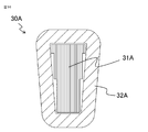
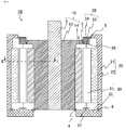
- FIG. 15 is a cross-sectional view taken along a rotation axis showing the structure of the rotary electric machine 1A according to the sixth embodiment.
- the rotary electric machine 1A includes two rotors, a counterload side rotor 10A and a load side rotor 20A, and a stator 30A sandwiched between the two rotors in the radial direction, and is configured as a double rotor type axial gap motor. Has been done.
- the counterload side rotor 10A includes a shaft 2A, a counterload side boss 12A press-fitted and fixed to the shaft 2A, and a permanent magnet 14A adhesively fixed to the load side of the counterload side boss 12A.
- the load-side rotor 20A includes a load-side boss 21A fixed to the shaft 2A and a permanent magnet 22A adhesively fixed to the non-load-side of the load-side boss 21A.
- the stator 30A is arranged between the counterload side rotor 10A and the load side rotor 20A, and the load side inner bearing 3A and the counterload side inner bearing 4A rotatably hold the counterload side rotor 10A and the load side rotor 20A, respectively.
- the stator core 31A is arranged between the outer diameter side holding member 35A and the inner diameter side holding member 33A in the radial direction, and the stator coil 32A is wound around the stator core 31A.
- the outer diameter side holding member 35A is attached to the counterload side base 39A and the load side base 39B arranged apart from the shaft 2A, and is two rotors, the counterload side rotor 10A and the load side. It surrounds the rotor 20A.
- the shaft 2A protrudes from the central portion of the load-side base 39B so as to be rotatable, and is separated from the load-side base 39B.
- stator core 31A thin electromagnetic steel plates long in the radial direction are laminated in the substantially circumferential direction, that is, in the rotational direction.
- both sides of the counterload side rotor 10A side and the load side rotor 20A side in the radial direction extend and project, and the tip portion 31Ac on the outer diameter side bends outward in the axial direction. It has an L-shaped tip and is held by engaging the L-shape with the groove 35Aa of the outer diameter side holding member 35A.
- the tip portion 31Ad on the inner diameter side of the stator core 31A has an L-shaped tip portion bent inward in the axial direction, and is engaged with and fixed to the L-shaped groove portion 33Ab provided on the inner diameter side holding member 33A. ing.
- the natural length of the portion where both the distal end portions 31Ac and 31Ad of the stator core 31A are engaged is L-shaped provided on the bottom surface of the groove portion 35Aa of the outer diameter side holding member 35A and the outer portion of the inner diameter side holding member 33A. It is configured to be shorter than the length L with the bottom surface of the groove portion 33Ab. Therefore, the stator core 31A is stretched in the radial direction and tensile stress is applied.
- FIG. 16 is a cross-sectional view showing the structure of the stator 30A, and is a partial cross-sectional view in the direction of the DD line in FIG.
- the rotary electric machine 1A is configured as a centralized winding of 10 poles and 12 slots.
- the stator core 31A is formed by laminating thin steel plates long in the radial direction in the substantially circumferential direction. Both the non-load side rotor 10A and the load side rotor 20A rotate at the same angular velocity.
- the thin steel plate of the stator core 31A is an electromagnetic steel plate manufactured by rolling, and the rolling direction is arranged so as to be the axial direction of the stator core 31A, that is, the direction in which the counterload side rotor 10A and the load side rotor 20A face each other. Has been done.
- the stator core 31A is fixed by applying tensile stress as in the first to fifth embodiments. Therefore, it can be configured without deterioration of magnetic characteristics due to stress, torque is improved, and it is possible to provide a highly efficient rotary electric machine.
- FIG. 17 is a cross-sectional view along a rotation axis showing the structure of the magnetic gear 1B according to the seventh embodiment
- FIG. 18 is a partial cross-sectional view in the EE line direction.
- the magnetic gear 1B does not include the stator coil 32
- FIG. 17 corresponds to the one in which the stator coil 32 is not wound around the stator core 31 in FIG. 13 of the fifth embodiment.
- the stator core 31 is flat and does not have bent portions on both sides in the radial direction.
- the stator core 31 acts as a pole piece that modulates the magnetic flux of the inner rotor 10 and the outer rotor 20 with respect to the inner rotor 10 and the outer rotor 20 depending on the magnitude of the magnetic resistance depending on the presence or absence of the stator core 31 in the circumferential direction.
- the inner rotor 10 and the outer rotor 20 of the magnetic gear 1B are not connected to each other.
- the inner rotor 10 rotates counterclockwise in the figure
- the outer rotor 20 rotates clockwise in the figure at the same electric angular velocity as the inner rotor 10.
- the number of poles of the outer rotor 20 is 60
- the number of poles of the inner rotor 10 is 12, and the number of poles of the outer rotor 20 is 5 times the number of poles of the inner rotor 10
- a magnetic gear having a reduction ratio of 5 is configured. can do.
- the rotation directions of the inner rotor 10 and the outer rotor 20 are the same, but they may be in opposite directions.
- the number of stator cores 31, which are pole pieces may be 72 instead of 48.
- the number of poles of the inner rotor 10 and the outer rotor 20 may be set as magnetic gears according to the gear ratio of the object driven by the inner rotor 10 and the outer rotor 20.
- the stator core 31 is stretched in the axial direction and fixed in a state where tensile stress is applied, so that the magnetic characteristics of the stator core 31 are not deteriorated. It will be possible to hold it in. This makes it possible to increase the efficiency and torque of the magnetic gear.
- FIG. 19 is a cross-sectional view taken along the movable axis of the linear motor 1C according to the eighth embodiment.
- the linear motor 1C has a stator (stator) 30C sandwiched between two movers 10C and 20C.
- the first mover 10C on one side of the stator 30C and the second mover 20C on the other side are each movably held in the direction of an arrow in the figure by a linear guide (not shown).
- a permanent magnet 14C is attached to the first movable base 12C of the first movable element 10C.
- a permanent magnet 22C is attached to the second movable base 21C.
- the stator 30C has a stator core 31C and a stator coil 32C wound around the stator core 31C.
- the stator core 31C is stretched in a direction perpendicular to the movable direction of the first mover 10C and the second mover 20C and parallel to the first mover 10C and the second mover 20C to hold both ends thereof.
- a tensile stress is applied to the stator core 31C in the stretching direction of the stator core 31C, and both ends thereof are held and fixed by, for example, bolts.
- the stator core 31C is configured by laminating thin plates as in the first to sixth embodiments.
- stator core 31C is a thin plate rolled so that the rolling direction faces the first mover 10C and the second mover 20C, and the first mover 10C and the second mover 20C are movable. It is configured by stacking in the direction.
- the same effect as that of the first embodiment is obtained. That is, it is possible to hold the stator core 31C without deteriorating the magnetic characteristics. This makes it possible to increase the efficiency and torque of the linear motor.
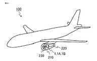
- FIG. 20 is a diagram showing an example of the aircraft 100 according to the ninth embodiment, and is equipped with the electromagnetic devices described in the first to seventh embodiments.
- a fan 230, a rotary electric machine 1, 1A, a magnetic gear 1B, and an engine 220 are arranged in an engine case 210 of an aircraft 100 by being connected by a shaft.
- the rotary electric machines 1 and 1A are motors and are used to drive the fan 230, and the magnetic gear 1B is used as a transmission for accelerating and decelerating.
- the rotation speed is between the fan 230 and the rotary electric machines 1, 1A, or between the rotary electric machines 1, 1A and the engine 220, or both. It may be equipped with a gear that changes.
- the gear may be a mechanical gear such as a spur gear or a planetary gear, but a magnetic gear 1B may be mounted.
- the rotary electric machines 1 and 1A are mounted, in FIG. 20, the rotary electric machines 1 and 1A and the engine 220 are arranged coaxially with respect to the fan 230, but even if they are configured on different axes via gears or the like. It has the same effect.
- tensile stress is applied to the stator core, so that the stator core can be reliably held without deteriorating the magnetic characteristics and a high torque output can be obtained. It is suitable for application to a rotating object mounted on an aircraft. Further, since the magnetic gear shown in the seventh embodiment surely holds the stator core without deteriorating the magnetic characteristics and has no wear points as compared with the mechanical gear, it can be used as a mechanical component mounted on an aircraft. Is suitable for application.
- FIG. 21 is a diagram showing another example of the aircraft 100 according to the ninth embodiment
- FIG. 21A is a schematic enlarged view of the aircraft 100 having a fan case 240 at the tail
- FIG. 21B is a schematic enlarged view of the fan case 240.
- the electromagnetic devices described in the first to seventh embodiments are mounted.
- the electromagnetic device is housed in the same engine case 210 as the engine 220, but as shown in FIG. 21, the electromagnetic device may be housed in a case different from the engine 220 to drive the driven object.
- FIG. 21 shows an example in which the rotary electric machines 1 and 1A or the magnetic gear 1B are connected to the fan 230 by a shaft in the fan case 240 at the tail. When the magnetic gear 1B is connected, the rotary electric machines 1, 1A or the engine 220 are further connected and driven.
- the aircraft 100 does not have an engine 220, and may be equipped with rotary electric machines 1 and 1A, which are electromagnetic devices, as a drive power source. Further, although not shown, it may be attached to a wing such as a helicopter or a multicopter having a plurality of rotary wings instead of the fixed-wing aircraft 100 and used as a drive source.
- rotary electric machines 1 and 1A which are electromagnetic devices, as a drive power source.
- it may be attached to a wing such as a helicopter or a multicopter having a plurality of rotary wings instead of the fixed-wing aircraft 100 and used as a drive source.
- the stator core is surely held without deteriorating the magnetic characteristics and a high torque output is obtained. Since it can be obtained, the cruising range per fuel can be improved.
- the rotary electric machines 1 and 1A are motors, but the same effect can be obtained even if they operate as a generator.
Landscapes
- Engineering & Computer Science (AREA)
- Power Engineering (AREA)
- Iron Core Of Rotating Electric Machines (AREA)
- Permanent Magnet Type Synchronous Machine (AREA)
- Aviation & Aerospace Engineering (AREA)
Priority Applications (4)
| Application Number | Priority Date | Filing Date | Title |
|---|---|---|---|
| DE112021003015.9T DE112021003015T5 (de) | 2020-05-29 | 2021-01-21 | Elektromagnetische einrichtung und luftfahrzeug, in dem die elektromagnetische einrichtung verwendet wird |
| US17/917,261 US12199479B2 (en) | 2020-05-29 | 2021-01-21 | Electromagnetic device having stator core formed with stacked thin sheets and aircraft in which electromagnetic device is used |
| JP2022527494A JP7361914B2 (ja) | 2020-05-29 | 2021-01-21 | 電磁機器及び電磁機器を用いた航空機 |
| CN202180037303.9A CN115917926A (zh) | 2020-05-29 | 2021-01-21 | 电磁设备以及使用电磁设备的飞机 |
Applications Claiming Priority (2)
| Application Number | Priority Date | Filing Date | Title |
|---|---|---|---|
| JP2020-094053 | 2020-05-29 | ||
| JP2020094053 | 2020-05-29 |
Publications (1)
| Publication Number | Publication Date |
|---|---|
| WO2021240870A1 true WO2021240870A1 (ja) | 2021-12-02 |
Family
ID=78744188
Family Applications (1)
| Application Number | Title | Priority Date | Filing Date |
|---|---|---|---|
| PCT/JP2021/002029 Ceased WO2021240870A1 (ja) | 2020-05-29 | 2021-01-21 | 電磁機器及び電磁機器を用いた航空機 |
Country Status (5)
| Country | Link |
|---|---|
| US (1) | US12199479B2 (https=) |
| JP (1) | JP7361914B2 (https=) |
| CN (1) | CN115917926A (https=) |
| DE (1) | DE112021003015T5 (https=) |
| WO (1) | WO2021240870A1 (https=) |
Families Citing this family (1)
| Publication number | Priority date | Publication date | Assignee | Title |
|---|---|---|---|---|
| CN115715450A (zh) * | 2020-05-29 | 2023-02-24 | 三菱电机株式会社 | 旋转电机以及使用旋转电机的飞机 |
Citations (3)
| Publication number | Priority date | Publication date | Assignee | Title |
|---|---|---|---|---|
| JP2006025484A (ja) * | 2004-07-06 | 2006-01-26 | Nissan Motor Co Ltd | ラジアル回転電機のステータ構造 |
| JP2010178599A (ja) * | 2009-02-02 | 2010-08-12 | Mazda Motor Corp | 回転電機 |
| JP2010178588A (ja) * | 2009-02-02 | 2010-08-12 | Mazda Motor Corp | 回転電機 |
Family Cites Families (13)
| Publication number | Priority date | Publication date | Assignee | Title |
|---|---|---|---|---|
| JP2010016932A (ja) | 2008-07-01 | 2010-01-21 | Mazda Motor Corp | 回転電機のステータ構造 |
| US10608482B2 (en) * | 2015-06-19 | 2020-03-31 | Nidec Corporation | Method of manufacturing stator core, method of inspecting stator core, stator core, and motor |
| CN108604850B (zh) * | 2016-02-03 | 2020-12-15 | 三菱电机株式会社 | 旋转电机 |
| JP6801396B2 (ja) | 2016-11-25 | 2020-12-16 | トヨタ自動車株式会社 | 二重ロータ構造のモータ |
| JP6489559B2 (ja) * | 2017-02-16 | 2019-03-27 | 本田技研工業株式会社 | 回転電機用コア及び回転電機用コアの製造方法 |
| JP2019037084A (ja) | 2017-08-18 | 2019-03-07 | トヨタ自動車株式会社 | ダブルロータ型の三相回転電機 |
| JP7222341B2 (ja) * | 2019-11-11 | 2023-02-15 | トヨタ自動車株式会社 | 回転電機 |
| JP2021175263A (ja) * | 2020-04-24 | 2021-11-01 | セイコーエプソン株式会社 | アキシャルギャップモーター |
| CN115715450A (zh) * | 2020-05-29 | 2023-02-24 | 三菱电机株式会社 | 旋转电机以及使用旋转电机的飞机 |
| WO2022153517A1 (ja) * | 2021-01-18 | 2022-07-21 | 三菱電機株式会社 | 回転電機 |
| US20240072594A1 (en) * | 2021-03-24 | 2024-02-29 | Mitsubishi Electric Corporation | Synchronous reluctance motor |
| JP7203175B1 (ja) * | 2021-10-18 | 2023-01-12 | 三菱電機株式会社 | 回転電機 |
| JP2024056531A (ja) * | 2022-10-11 | 2024-04-23 | 株式会社デンソー | 回転電機 |
-
2021
- 2021-01-21 CN CN202180037303.9A patent/CN115917926A/zh not_active Withdrawn
- 2021-01-21 US US17/917,261 patent/US12199479B2/en active Active
- 2021-01-21 WO PCT/JP2021/002029 patent/WO2021240870A1/ja not_active Ceased
- 2021-01-21 DE DE112021003015.9T patent/DE112021003015T5/de not_active Withdrawn
- 2021-01-21 JP JP2022527494A patent/JP7361914B2/ja active Active
Patent Citations (3)
| Publication number | Priority date | Publication date | Assignee | Title |
|---|---|---|---|---|
| JP2006025484A (ja) * | 2004-07-06 | 2006-01-26 | Nissan Motor Co Ltd | ラジアル回転電機のステータ構造 |
| JP2010178599A (ja) * | 2009-02-02 | 2010-08-12 | Mazda Motor Corp | 回転電機 |
| JP2010178588A (ja) * | 2009-02-02 | 2010-08-12 | Mazda Motor Corp | 回転電機 |
Also Published As
| Publication number | Publication date |
|---|---|
| DE112021003015T5 (de) | 2023-03-23 |
| JP7361914B2 (ja) | 2023-10-16 |
| JPWO2021240870A1 (https=) | 2021-12-02 |
| US20230163670A1 (en) | 2023-05-25 |
| US12199479B2 (en) | 2025-01-14 |
| CN115917926A (zh) | 2023-04-04 |
Similar Documents
| Publication | Publication Date | Title |
|---|---|---|
| EP3902105B1 (en) | Laminated core and rotating electric machine | |
| EP3902113B1 (en) | Laminated core and electric motor | |
| US7714479B2 (en) | Segmented composite rotor | |
| US8860275B2 (en) | Multi-layer arc-shaped permanent magnet machine with reduced rotational stress | |
| JP6649238B2 (ja) | 回転電機およびロボット装置 | |
| JP7361915B2 (ja) | 回転電機及び回転電機を用いた航空機 | |
| CN107204693B (zh) | 旋转电机、曳引机以及电梯 | |
| CN102347655A (zh) | 旋转电机、直动电机以及风力发电系统 | |
| JP2014180094A (ja) | 永久磁石回転電機およびエレベーター駆動巻上機 | |
| WO2022258948A1 (en) | Magnetically geared apparatus and rotor | |
| US20220368183A1 (en) | Rotor for a synchronous machine | |
| JP2018164378A (ja) | Ipmロータ用磁石、ipmロータおよびipmロータ用磁石の製造方法 | |
| JP4369384B2 (ja) | 回転電機 | |
| US7692354B2 (en) | Rotary electric machine with reduced torque ripple | |
| JP7361914B2 (ja) | 電磁機器及び電磁機器を用いた航空機 | |
| CN106100271B (zh) | 轴径向磁通的调磁电机 | |
| KR102456478B1 (ko) | 로터어셈블리 및 이를 포함하는 모터 | |
| EP3291414A2 (en) | Switched reluctance motor with axial laminated construction | |
| CN111463914A (zh) | 用于轴向通量电动机器的混合转子 | |
| JP2020167903A (ja) | 回転電機及びこれを用いた推進装置 | |
| US10243417B2 (en) | Electric motor having a low short-circuit torque, drive device with a plurality of motors and method for producing such a motor | |
| JP2014017999A (ja) | モータ、および、建機用ハイブリッド構造体 | |
| EP2856611B1 (en) | Rotor | |
| JP4459886B2 (ja) | ステータおよびモータ | |
| EP4329152A1 (en) | Rotor |
Legal Events
| Date | Code | Title | Description |
|---|---|---|---|
| 121 | Ep: the epo has been informed by wipo that ep was designated in this application |
Ref document number: 21813119 Country of ref document: EP Kind code of ref document: A1 |
|
| ENP | Entry into the national phase |
Ref document number: 2022527494 Country of ref document: JP Kind code of ref document: A |
|
| 122 | Ep: pct application non-entry in european phase |
Ref document number: 21813119 Country of ref document: EP Kind code of ref document: A1 |