WO2021235030A1 - ロボット制御システム、ロボット制御装置、ロボット制御方法及びプログラム - Google Patents
ロボット制御システム、ロボット制御装置、ロボット制御方法及びプログラム Download PDFInfo
- Publication number
- WO2021235030A1 WO2021235030A1 PCT/JP2021/005620 JP2021005620W WO2021235030A1 WO 2021235030 A1 WO2021235030 A1 WO 2021235030A1 JP 2021005620 W JP2021005620 W JP 2021005620W WO 2021235030 A1 WO2021235030 A1 WO 2021235030A1
- Authority
- WO
- WIPO (PCT)
- Prior art keywords
- teaching
- data
- reproduction
- unit
- robot control
- Prior art date
- Legal status (The legal status is an assumption and is not a legal conclusion. Google has not performed a legal analysis and makes no representation as to the accuracy of the status listed.)
- Ceased
Links
Images




Classifications
-
- B—PERFORMING OPERATIONS; TRANSPORTING
- B25—HAND TOOLS; PORTABLE POWER-DRIVEN TOOLS; MANIPULATORS
- B25J—MANIPULATORS; CHAMBERS PROVIDED WITH MANIPULATION DEVICES
- B25J13/00—Controls for manipulators
- B25J13/08—Controls for manipulators by means of sensing devices, e.g. viewing or touching devices
-
- B—PERFORMING OPERATIONS; TRANSPORTING
- B25—HAND TOOLS; PORTABLE POWER-DRIVEN TOOLS; MANIPULATORS
- B25J—MANIPULATORS; CHAMBERS PROVIDED WITH MANIPULATION DEVICES
- B25J9/00—Program-controlled manipulators
- B25J9/16—Program controls
- B25J9/1656—Program controls characterised by programming, planning systems for manipulators
Definitions
- the present invention relates to a robot control system, a robot control device, a robot control method, and a program.
- Patent Document 1 discloses a picking robot that teaches the positions of parts in advance and picks the parts based on the taught positions.
- Patent Document 1 makes it possible to reduce the man-hours for teaching the picking robot by sharing the gripping positions of a plurality of workpieces (objects to be picked).
- this picking robot it is premised that there is no difference between the work position at the time of teaching and the work position at the time of performing the picking process (during reproduction) based on the teaching data created by the teaching process. There is. Therefore, if there is a deviation in the work position between the time of teaching and the time of reproduction, an appropriate picking process cannot be performed.
- the robot control device is A robot control device that moves a robot arm equipped with a three-dimensional measurement camera that measures the three-dimensional position of an object by reproducing teaching data taught in advance.
- a reference position acquisition unit that acquires a reference position, which is a three-dimensional position of the target object at the time of teaching, from the three-dimensional measurement camera.
- a reproduction position acquisition unit that acquires a reproduction position, which is a three-dimensional position of the target object at the time of reproduction, from the three-dimensional measurement camera.
- a conversion data calculation unit that calculates conversion data for converting a reference position acquired by the reference position acquisition unit into a reproduction position acquired by the reproduction position acquisition unit, and a conversion data calculation unit.
- a reproduction unit that moves the robot arm by converting the teaching data using the conversion data calculated by the conversion data calculation unit and then reproducing the teaching data. To prepare for.
- a point cloud data editing unit for editing the point cloud data representing the reference position is further provided.
- the reference position acquisition unit acquires a reference position represented by the point cloud data edited by the point cloud data editing unit. You may do so.
- the robot control method is: It is a robot control method that moves a robot arm equipped with a 3D measurement camera that measures the 3D position of a target object by reproducing teaching data taught in advance.
- a conversion data calculation step for calculating conversion data for converting a reference position acquired in the reference position acquisition step into a reproduction position acquired in the reproduction position acquisition step, and a conversion data calculation step.
- the present invention includes a re-teaching step of replaying the teaching data from the first teaching data to the correction-needed teaching data, which is the teaching data requiring correction, and then receiving the teaching again to correct the correction-necessary teaching data. You may do so.
- the program according to the fourth aspect of the present invention is To the computer of the robot control device that moves the robot arm equipped with the 3D measurement camera that measures the 3D position of the target object by reproducing the teaching data taught in advance.
- a re-teaching step of replaying the teaching data from the first teaching data to the correction-needed teaching data, which is the teaching data requiring correction, and then receiving the teaching again to correct the correction-necessary teaching data. May be executed.
- the 3D measurement camera 150 is a camera that can measure the distance to a photographed object, and is also called a 3D sensor, a depth sensor, a distance measurement sensor, or the like.
- a 3D sensor As the device configuration of such a camera, there are one composed of two cameras, one composed of one camera and one projector, one composed of two cameras and one projector, and the like.
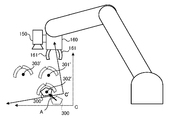
- the device configuration of the three-dimensional measurement camera 150 may be any configuration. As shown in FIG. 1, the three-dimensional measurement camera 150 is attached to the robot arm 160 and photographs an object object 310 existing in front of the robot arm 160.
- the robot control device 100 can acquire the three-dimensional position of the target object 310 by acquiring the data of the point cloud described later from the image data of the target object 310 taken by the three-dimensional measurement camera 150.
- the robot control device 100 includes a control unit 110, a storage unit 120, an image input unit 131, a display unit 132, an operation input unit 133, and a robot control unit 134.
- the storage unit 120 is composed of a RAM (Random Access Memory), a ROM (Read Only Memory), and the like.
- the storage unit 120 stores in advance a program or the like for performing various processes by the control unit 110. Further, the storage unit 120 stores image data taken by the three-dimensional measurement camera 150, data used by the control unit 110 for arithmetic processing, and the like.
- the image input unit 131 is an interface between the control unit 110 and the three-dimensional measurement camera 150.
- the image data taken by the three-dimensional measurement camera 150 is input to the control unit 110 via the image input unit 131. Further, a shooting command to the three-dimensional measurement camera 150 is transmitted from the control unit 110 to the three-dimensional measurement camera 150 via the image input unit 131.
- the display unit 132 is a device for displaying image data taken by the three-dimensional measurement camera 150, an operation UI (User Interface) screen of the robot arm 160, and the like.
- the display unit 132 includes a liquid crystal display and an organic EL (Electro-Luminescence) display.
- the robot control device 100 may include these displays as a display unit 132, or may include a display unit 132 as an interface for connecting an external display.
- the robot control device 100 displays image data or the like on an external display connected via the display unit 132.
- the operation input unit 133 is a device that receives a user's operation input to the robot control device 100, and is, for example, a keyboard, a mouse, a touch panel, or the like.
- the robot control device 100 receives instructions and the like from the user via the operation input unit 133.
- the robot control unit 134 is an interface between the control unit 110 and the robot arm 160.
- the command to move the robot arm 160 is transmitted from the control unit 110 to the robot arm 160 via the robot control unit 134. Further, the control unit 110 can acquire the current three-dimensional position of the robot arm 160 via the robot control unit 134.
- the reproduction position acquisition unit 112 acquires the reproduction position, which is the three-dimensional position of the object to be photographed at the time of reproduction, from the image photographed by the three-dimensional measurement camera 150.
- the conversion data calculation unit 113 calculates conversion data for converting the reference position acquired by the reference position acquisition unit 111 into the reproduction position acquired by the reproduction position acquisition unit 112.
- the reproduction unit 114 converts the teaching data using the conversion data calculated by the conversion data calculation unit 113, and issues an operation command to the robot arm 160 from the robot control unit 134 to the robot arm 160 based on the converted teaching data. Move the robot arm by transmitting. It should be noted that transmitting an operation command to the robot arm 160 from the robot control unit 134 to the robot arm 160 based on the teaching data is referred to as "reproducing the teaching data”.
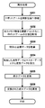
- Step S103 acquires the three-dimensional position data (point cloud data) of the point cloud of the target object 310 (step S103).
- Step S103 is also referred to as a reference position acquisition step.
- the three-dimensional position of the point group acquired here is represented by the coordinates (camera coordinates) in the coordinate system (camera coordinate system) seen from the three-dimensional measurement camera 150, but the three dimensions of the robot arm 160. Similar to the position, it may be represented by coordinates in the world coordinate system with respect to the earth, for example.
- the point cloud is a set of three-dimensional coordinate (XYZ coordinate) data in which a three-dimensional object is discreteized in dot units (for example, 0.1 mm units).
- the distance to each feature point obtained from the image data taken by the 3D measurement camera 150 and the 3D position of the 3D measurement camera 150 at the time of shooting (the 3D measurement camera 150 is attached to the robot arm 160). Therefore, it can be calculated from the three-dimensional position of the robot arm 160), and the three-dimensional coordinates of each feature point are obtained, and the set of the three-dimensional coordinate data of each feature point is used as the point cloud data.
- the feature point is a point indicating a characteristic portion (edge portion, color boundary portion, etc.) included in the image data.
- the point cloud data acquired here is data representing a reference position which is a three-dimensional position of the target object 310 at the time of teaching.
- the point cloud is not limited to the feature points, and a set of three-dimensional coordinate data obtained by dissociating the entire surface of the object included in the image data may be used.
- a set of three-dimensional coordinate data of the feature points is treated as a point cloud.
- the reference position acquisition unit 111 edits the point cloud data acquired in step S103 (step S104).
- Step S104 is also referred to as an editing step.
- the reference position acquisition unit 111 functions as a point cloud data editing unit. Since the point cloud data acquired in step S103 includes points other than the target object 310 such as the background, unnecessary points are deleted in step S104. Further, in the conversion data calculation step described later, a process of adjusting the resolution as necessary is also performed in step S104 so that the matching process with the master data is appropriately performed.
- the coordinates of the robot arm 160 and the coordinates of the point cloud data are represented by the coordinates in the same coordinate system (for example, the world coordinate system), it is necessary to convert the coordinates of the point cloud data (to the coordinates in the robot coordinate system). It may be stored in the storage unit 120 as it is as master data.
- Step S201 is the same process as step S101 of the teaching process (FIG. 2).
- Step S202 is the same process as step S102 of the teaching process.
- Step S203 is the same process as step S103 of the teaching process, but the point cloud data acquired in step S203 is data representing the reproduction position which is the three-dimensional position of the target object 310 at the time of reproduction.
- Step S203 is also referred to as a reproduction position acquisition step.
- the point cloud data acquired here includes not only the target object 310 but also the point cloud of unnecessary parts such as the background (table 320 and the like).
- the conversion data calculation unit 113 matches the point cloud data acquired in step S203 with the master data stored in the storage unit 120 in step S105 of the teaching process, and reproduces the coordinates (reference position) at the time of teaching.
- the conversion data to be converted into the time coordinates (reproduction position) is calculated (step S204).
- Step S204 is also referred to as a conversion data calculation step.
- the conversion data calculation unit 113 converts the point cloud data (coordinates at the time of reproduction) and the master data (coordinates at the time of teaching) acquired in step S203 into coordinates in the same coordinate system (for example, robot coordinate system).
- matching is performed using an ICP (Iterative Closet Point) algorithm or the like, and a coordinate conversion matrix A for converting the coordinates at the time of teaching to the coordinates at the time of reproduction is calculated.
- ICP Intelligent Closet Point
- step S203 there may be a plurality of target objects 310 in the image data taken by the three-dimensional measurement camera 150, such as a plurality of target objects 310 existing on the table 320.
- the conversion data calculation unit 113 selects one target object 310 that is considered to be the most appropriate from the plurality of target objects 310, and sets the point group data of the selected target object 310. Match with master data.
- a method of selecting one of the most appropriate target objects 310 for example, the goodness of fit of the point group of each target object 310 is evaluated, and the target object 310 having the highest goodness of fit with the master data is selected. There is a method of selection. This method will be described below.
- the number of a plurality of target objects 310 existing in the image data acquired in step S202 is represented by n. Further, the number of points included in the master data is represented by N. Then, among the points included in the master data, the distance from the point cloud (corresponding point to the point included in the master data) included in the point cloud of the i-th (i is an integer of 1 or more and n or less) target object 310. Represents the number of points within a predetermined threshold in Mi. At this time, the goodness of fit of the i-th target object 310 is represented by Mi / N.
- the conversion data calculation unit 113 selects the target object 310 having the highest goodness of fit (Mi / N). For example, by such a method, the conversion data calculation unit 113 can select one of the most appropriate target objects 310 from the plurality of target objects 310.
- step S204 uses the conversion data (coordinate transformation matrix A) calculated in step S204 to convert the coordinates of the teaching points included in the teaching data stored in the storage unit 120 into the coordinates at the time of reproduction.
- Convert step S205.
- the coordinates of the master data are the coordinates at the time of reproduction (coordinates in the coordinate system C at the time of teaching are used in the coordinate system C). It is converted to (coordinates projected on').
- Step S205 is also referred to as a conversion step.
- some robots may have a function of defining a coordinate system C'used when designating the position of the robot arm 160 and switching the coordinate system C at the time of teaching to the defined coordinate system C'.
- This function causes the robot to switch the reference coordinate system from the coordinate system C (the coordinate system at the time of teaching) to the coordinate system C'(the coordinate system that is the reference of the current playback position).
- the coordinate system C' the coordinate system that is the reference of the current playback position.
- the reproduction unit 114 defines the coordinate system C'at the time of reproduction instead of converting the coordinates as described above, and tells the robot the coordinate system of the master data (coordinates at the time of teaching).
- the coordinates (in the coordinate system C) at the time of teaching shown in FIG. 4 are the coordinates at the time of reproduction (coordinate system C) as shown in FIG. It may be possible to use it as it is (coordinates projected on').
- an object positioning error of the 3D measuring camera 150 may occur between the time of teaching and the time of reproduction. From the three-dimensional measurement camera 150, it is observed as the same as the positional deviation of the target object. Therefore, the influence of this object positioning error can also be removed by the above-mentioned processing.
- the teaching data stored in the storage unit 120 by the teaching process is represented by the coordinates in the coordinate system C
- the teaching data obtained by the re-teaching is also represented by the coordinates in the coordinate system C.
- the teaching data obtained by re-teaching regardless of whether the robot has or does not have the function of switching the coordinate system used when specifying the position of the robot arm 160.
- step S106 of the teaching process the robot arm 160 is actually moved to teach. This is because it is considered that it is easier for the user to teach by actually moving the robot arm 160, and it is often possible to teach accurately.
- the display unit 132 may confirm the movement of the robot arm 160 and teach the robot arm 160 without actually moving the robot arm 160.
- the robot control device 100 controls both the three-dimensional measurement camera 150 and the robot arm 160, but the robot control device 100 does not necessarily have to control both of them.
- the robot control system 1001 includes an image processing device 200 in addition to the robot control device 101, and the two devices are configured to be able to communicate with each other via the communication unit 140 and the communication unit 240. You may be.
- the robot control device 101 controls the robot arm 160
- the image processing device 200 controls the three-dimensional measurement camera 150.
- control unit 210, the storage unit 220, the image input unit 231, the display unit 232, and the operation input unit 233 shown in FIG. 10 are the control unit 110 and the storage unit 110 of the robot control device 100 (FIG. 1), respectively. It has the same functions and configurations as the unit 120, the image input unit 131, the display unit 132, and the operation input unit 133.
- the communication unit 140 and the communication unit 240 each include a device capable of communicating with each other. This communication may be wireless or wired.
- the communication unit 140 and the communication unit 240 are each provided with a wireless LAN (Local Area Network) device, and data communication with each other is possible.
- LAN Local Area Network
- the present invention is applicable to a robot control system, a robot control device, a robot control method, and a program that can eliminate the influence of the deviation even if the position of the target object is deviated between the time of teaching and the time of reproduction.
Landscapes
- Engineering & Computer Science (AREA)
- Robotics (AREA)
- Mechanical Engineering (AREA)
- Human Computer Interaction (AREA)
- Numerical Control (AREA)
- Manipulator (AREA)
Priority Applications (1)
| Application Number | Priority Date | Filing Date | Title |
|---|---|---|---|
| CN202180059579.7A CN116133801A (zh) | 2019-10-30 | 2021-02-16 | 机器人控制系统、机器人控制装置、机器人控制方法及程序 |
Applications Claiming Priority (3)
| Application Number | Priority Date | Filing Date | Title |
|---|---|---|---|
| JP2019197058 | 2019-10-30 | ||
| JP2020-089195 | 2020-05-21 | ||
| JP2020089195A JP7199101B2 (ja) | 2019-10-30 | 2020-05-21 | ロボット制御システム、ロボット制御装置、ロボット制御方法及びプログラム |
Publications (1)
| Publication Number | Publication Date |
|---|---|
| WO2021235030A1 true WO2021235030A1 (ja) | 2021-11-25 |
Family
ID=75712192
Family Applications (1)
| Application Number | Title | Priority Date | Filing Date |
|---|---|---|---|
| PCT/JP2021/005620 Ceased WO2021235030A1 (ja) | 2019-10-30 | 2021-02-16 | ロボット制御システム、ロボット制御装置、ロボット制御方法及びプログラム |
Country Status (3)
| Country | Link |
|---|---|
| JP (1) | JP7199101B2 (https=) |
| CN (1) | CN116133801A (https=) |
| WO (1) | WO2021235030A1 (https=) |
Families Citing this family (4)
| Publication number | Priority date | Publication date | Assignee | Title |
|---|---|---|---|---|
| WO2023102647A1 (en) * | 2021-12-06 | 2023-06-15 | University Of Manitoba | Method for automated 3d part localization and adjustment of robot end-effectors |
| JP7833769B2 (ja) * | 2022-03-30 | 2026-03-23 | Johnan株式会社 | ネットワークシステム、コンピュータ、および深層学習方法 |
| CN118809624B (zh) * | 2024-09-19 | 2024-11-15 | 天津视崛智能科技有限公司 | 一种机械臂分拣抓取控制方法、系统及装置 |
| KR20260046569A (ko) * | 2024-09-30 | 2026-04-07 | 주식회사 가치소프트 | 디지털 티칭 방법 및 그 장치 |
Citations (5)
| Publication number | Priority date | Publication date | Assignee | Title |
|---|---|---|---|---|
| US4675502A (en) * | 1985-12-23 | 1987-06-23 | General Electric Company | Real time tracking control for taught path robots |
| JP2009248214A (ja) * | 2008-04-03 | 2009-10-29 | Kanto Auto Works Ltd | 画像処理装置、およびロボット制御システム |
| JP2010172969A (ja) * | 2009-01-27 | 2010-08-12 | Yaskawa Electric Corp | ロボットシステムおよびロボットの制御方法 |
| JP2018001393A (ja) * | 2016-07-08 | 2018-01-11 | キヤノン株式会社 | ロボット装置、ロボット制御方法、プログラム及び記録媒体 |
| KR102096897B1 (ko) * | 2018-12-31 | 2020-04-03 | (주) 엠엔비젼 | 3d 도면 파일을 이용하여 로봇 제어에 필요한 자동 티칭 시스템 및 티칭 방법 |
Family Cites Families (5)
| Publication number | Priority date | Publication date | Assignee | Title |
|---|---|---|---|---|
| JP2011110621A (ja) * | 2009-11-24 | 2011-06-09 | Toyota Industries Corp | ロボットの教示データを作成する方法およびロボット教示システム |
| JP6108860B2 (ja) * | 2013-02-14 | 2017-04-05 | キヤノン株式会社 | ロボットシステム及びロボットシステムの制御方法 |
| JP2017100202A (ja) * | 2015-11-30 | 2017-06-08 | 株式会社アイキューブテクノロジ | ロボットシステム、制御装置、制御方法、及びプログラム |
| WO2019092792A1 (ja) * | 2017-11-07 | 2019-05-16 | 三菱電機株式会社 | 表示制御装置、表示制御方法および表示制御プログラム |
| JP7080068B2 (ja) * | 2018-02-16 | 2022-06-03 | 日本電産サンキョー株式会社 | ロボットの位置情報復元方法 |
-
2020
- 2020-05-21 JP JP2020089195A patent/JP7199101B2/ja active Active
-
2021
- 2021-02-16 CN CN202180059579.7A patent/CN116133801A/zh active Pending
- 2021-02-16 WO PCT/JP2021/005620 patent/WO2021235030A1/ja not_active Ceased
Patent Citations (5)
| Publication number | Priority date | Publication date | Assignee | Title |
|---|---|---|---|---|
| US4675502A (en) * | 1985-12-23 | 1987-06-23 | General Electric Company | Real time tracking control for taught path robots |
| JP2009248214A (ja) * | 2008-04-03 | 2009-10-29 | Kanto Auto Works Ltd | 画像処理装置、およびロボット制御システム |
| JP2010172969A (ja) * | 2009-01-27 | 2010-08-12 | Yaskawa Electric Corp | ロボットシステムおよびロボットの制御方法 |
| JP2018001393A (ja) * | 2016-07-08 | 2018-01-11 | キヤノン株式会社 | ロボット装置、ロボット制御方法、プログラム及び記録媒体 |
| KR102096897B1 (ko) * | 2018-12-31 | 2020-04-03 | (주) 엠엔비젼 | 3d 도면 파일을 이용하여 로봇 제어에 필요한 자동 티칭 시스템 및 티칭 방법 |
Also Published As
| Publication number | Publication date |
|---|---|
| JP2021070149A (ja) | 2021-05-06 |
| JP7199101B2 (ja) | 2023-01-05 |
| CN116133801A (zh) | 2023-05-16 |
Similar Documents
| Publication | Publication Date | Title |
|---|---|---|
| WO2021235030A1 (ja) | ロボット制御システム、ロボット制御装置、ロボット制御方法及びプログラム | |
| US11364636B2 (en) | Programming device and robot control method | |
| JP6640060B2 (ja) | ロボットシステム | |
| JP6892286B2 (ja) | 画像処理装置、画像処理方法、及びコンピュータプログラム | |
| CN102785249A (zh) | 机械手控制系统,机械手系统以及程序 | |
| JP2014014912A (ja) | ロボットシステム、ロボット、ロボット制御装置、ロボット制御方法、およびロボット制御プログラム | |
| CN104802186A (zh) | 制作用于拍摄工件的机器人程序的机器人程序设计装置 | |
| CN114080590B (zh) | 使用先进扫描技术的机器人料箱拾取系统和方法 | |
| JP2018001393A (ja) | ロボット装置、ロボット制御方法、プログラム及び記録媒体 | |
| US20200198137A1 (en) | Trajectory generation device, trajectory generation method, and robot system | |
| JP2018153874A (ja) | 提示装置、提示方法およびプログラム、ならびに作業システム | |
| WO2018043524A1 (ja) | ロボットシステム、ロボットシステム制御装置、およびロボットシステム制御方法 | |
| WO2022107684A1 (ja) | パラメータを調整する装置、ロボットシステム、方法、及びコンピュータプログラム | |
| CN109648568A (zh) | 机器人控制方法、系统及存储介质 | |
| JP4085671B2 (ja) | データ処理方法、データ処理プログラムおよび記録媒体 | |
| JP7334460B2 (ja) | 作業支援装置及び作業支援方法 | |
| JPH1079027A (ja) | 移動カメラ用の画像処理装置 | |
| CN112643718A (zh) | 图像处理设备及其控制方法和存储其控制程序的存储介质 | |
| JPH11153430A (ja) | 撮影画像管理装置およびそのプログラム記録媒体 | |
| JP3219182B2 (ja) | 監視制御装置におけるカメラ制御方法 | |
| JP2023017436A (ja) | ロボット制御装置 | |
| JP2018132847A (ja) | 情報処理装置、情報処理方法、およびプログラム | |
| JP7645145B2 (ja) | 教示データ修正装置 | |
| TWI853525B (zh) | 記錄有標記位置登記程式的非易失性的電腦可讀取媒體、標記位置登記裝置、方法以及其中使用的標記 | |
| JPH06110544A (ja) | ロボットの遠隔操作装置 |
Legal Events
| Date | Code | Title | Description |
|---|---|---|---|
| 121 | Ep: the epo has been informed by wipo that ep was designated in this application |
Ref document number: 21808182 Country of ref document: EP Kind code of ref document: A1 |
|
| NENP | Non-entry into the national phase |
Ref country code: DE |
|
| 122 | Ep: pct application non-entry in european phase |
Ref document number: 21808182 Country of ref document: EP Kind code of ref document: A1 |