WO2021234948A1 - 映像表示装置および輝度補正方法 - Google Patents
映像表示装置および輝度補正方法 Download PDFInfo
- Publication number
- WO2021234948A1 WO2021234948A1 PCT/JP2020/020306 JP2020020306W WO2021234948A1 WO 2021234948 A1 WO2021234948 A1 WO 2021234948A1 JP 2020020306 W JP2020020306 W JP 2020020306W WO 2021234948 A1 WO2021234948 A1 WO 2021234948A1
- Authority
- WO
- WIPO (PCT)
- Prior art keywords
- temperature
- correction coefficient
- correction
- unit
- video display
- Prior art date
- Legal status (The legal status is an assumption and is not a legal conclusion. Google has not performed a legal analysis and makes no representation as to the accuracy of the status listed.)
- Ceased
Links
Images






Classifications
-
- G—PHYSICS
- G09—EDUCATION; CRYPTOGRAPHY; DISPLAY; ADVERTISING; SEALS
- G09G—ARRANGEMENTS OR CIRCUITS FOR CONTROL OF INDICATING DEVICES USING STATIC MEANS TO PRESENT VARIABLE INFORMATION
- G09G3/00—Control arrangements or circuits, of interest only in connection with visual indicators other than cathode-ray tubes
- G09G3/20—Control arrangements or circuits, of interest only in connection with visual indicators other than cathode-ray tubes for presentation of an assembly of a number of characters, e.g. a page, by composing the assembly by combination of individual elements arranged in a matrix no fixed position being assigned to or needed to be assigned to the individual characters or partial characters
-
- G—PHYSICS
- G09—EDUCATION; CRYPTOGRAPHY; DISPLAY; ADVERTISING; SEALS
- G09G—ARRANGEMENTS OR CIRCUITS FOR CONTROL OF INDICATING DEVICES USING STATIC MEANS TO PRESENT VARIABLE INFORMATION
- G09G3/00—Control arrangements or circuits, of interest only in connection with visual indicators other than cathode-ray tubes
- G09G3/20—Control arrangements or circuits, of interest only in connection with visual indicators other than cathode-ray tubes for presentation of an assembly of a number of characters, e.g. a page, by composing the assembly by combination of individual elements arranged in a matrix no fixed position being assigned to or needed to be assigned to the individual characters or partial characters
- G09G3/22—Control arrangements or circuits, of interest only in connection with visual indicators other than cathode-ray tubes for presentation of an assembly of a number of characters, e.g. a page, by composing the assembly by combination of individual elements arranged in a matrix no fixed position being assigned to or needed to be assigned to the individual characters or partial characters using controlled light sources
- G09G3/30—Control arrangements or circuits, of interest only in connection with visual indicators other than cathode-ray tubes for presentation of an assembly of a number of characters, e.g. a page, by composing the assembly by combination of individual elements arranged in a matrix no fixed position being assigned to or needed to be assigned to the individual characters or partial characters using controlled light sources using electroluminescent panels
- G09G3/32—Control arrangements or circuits, of interest only in connection with visual indicators other than cathode-ray tubes for presentation of an assembly of a number of characters, e.g. a page, by composing the assembly by combination of individual elements arranged in a matrix no fixed position being assigned to or needed to be assigned to the individual characters or partial characters using controlled light sources using electroluminescent panels semiconductive, e.g. using light-emitting diodes [LED]
Definitions
- the present disclosure relates to a video display device having a plurality of LEDs (Light Emitting Diodes) and a brightness correction method.
- LEDs Light Emitting Diodes
- LED display devices having LEDs are increasingly used for displaying advertisements outdoors or indoors.
- LED display devices have mainly displayed moving images such as natural images and animations.
- LED display devices for indoor use have been narrowed in LED display devices for indoor use. Therefore, the viewing distance of the LED display device for indoor use is shortened. As a result, LED display devices are used for indoor applications such as conference room applications and monitoring applications. In particular, LED display devices for surveillance purposes often display, for example, a personal computer image close to a still image.
- Patent Document 1 discloses a configuration for reducing luminance unevenness (hereinafter, also referred to as “related configuration A”).
- related configuration A the luminosity of each LED as a pixel is corrected based on the correction coefficient.
- the luminosity characteristics of each LED on the display surface are made uniform.
- An image display device such as an LED display device is a display area in which a plurality of LEDs are arranged, and has a display area for displaying an image.
- a video display device having a configuration in which a plurality of regions having different heat dissipation characteristics exist in the display region.
- the video display device in order to suppress deterioration of the quality of the video displayed in the display area, it is a process of correcting the brightness of the pixels of the video to be displayed in the display area, and the plurality of regions. It is required to carry out the processing in consideration of the temperature of.
- the related configuration A cannot meet this requirement.
- the present disclosure has been made to solve such a problem, and in the display area in consideration of the temperature of a plurality of areas having different heat dissipation characteristics existing in the display area in which a plurality of LEDs are arranged. It is an object of the present invention to provide an image display device or the like capable of performing a process of correcting the brightness of a pixel of an image for display.
- the video display device has a display area for displaying video.
- the image display device includes a temperature measuring unit having a function of measuring temperature, and a plurality of LEDs (Light Emitting Diodes) as pixels for displaying the image are arranged in the display area.
- the display area includes a first region having a first heat dissipation characteristic and a second region having a second heat dissipation characteristic different from the first heat dissipation characteristic, and the temperature measuring unit is at the temperature of the first region. A certain first temperature and a second temperature which is a temperature of the second region are measured, and the image display device further performs a brightness correction process based on the first temperature and the second temperature.
- a correction coefficient specifying unit for specifying a correction coefficient is provided, and the luminance correction process is a process of correcting the brightness of pixels of a target image which is the image to be displayed in the display area, and the image display device specifies. Based on the luminance correction coefficient, the luminance correction process for correcting the luminance of the target pixel, which is a pixel of the target image, is performed.
- a plurality of LEDs are arranged in the display area.
- the display area includes a first area and a second area.
- the correction coefficient specifying unit specifies a luminance correction coefficient for performing the luminance correction process.
- the image display device performs the luminance correction process for correcting the luminance of the pixels of the image to be displayed in the display area based on the luminance correction coefficient.
- the luminance correction process is a process based on the first temperature of the first region and the second temperature of the second region. The first heat dissipation characteristic of the first region is different from the second heat dissipation characteristic of the second region.
- processing is performed to correct the brightness of the pixels of the image to be displayed in the display area in consideration of the temperature of the plurality of areas having different heat dissipation characteristics existing in the display area in which the plurality of LEDs are arranged. Can be done.
- FIG. It is a figure which shows the structure of the image display device which concerns on Embodiment 1.
- FIG. It is an exploded perspective view which shows the schematic structure of the display unit which concerns on Embodiment 1.
- FIG. It is an enlarged view of a part of FIG. It is a front view of the image display module which concerns on Embodiment 1.
- FIG. It is a block diagram which shows the structure of the image display module which concerns on Embodiment 1.
- FIG. It is a graph which shows the characteristic of LED.
- FIG. It is a block diagram which shows the structure of the control module which concerns on Embodiment 1.
- FIG. It is a figure which shows the plurality of temperature correction coefficients stored in the temperature correction coefficient storage part. It is a flowchart of the temperature correspondence brightness correction processing which concerns on Embodiment 1.
- FIG. It is a block diagram which shows the structure of the control module which concerns on modification 1.
- FIG. It is a flowchart of the temperature correspondence brightness correction process A which concerns on modification 1.
- FIG. It is a block diagram which shows the characteristic functional composition of a video display device. It is a hardware block diagram of a video display device.
- the dimensions, materials, shapes, relative arrangements, etc. of the components exemplified in the embodiment may be appropriately changed depending on the configuration of the device, various conditions, and the like.
- the dimensions of the components in the figure may differ from the actual dimensions.
- FIG. 1 is a diagram showing a configuration of a video display device 1000 according to the first embodiment.
- the image display device 1000 is an LED display device that displays an image by using an LED as a display element.
- the X direction, the Y direction, and the Z direction are orthogonal to each other.
- the X, Y, and Z directions shown in the figure below are also orthogonal to each other.
- the direction including the X direction and the direction opposite to the X direction (-X direction) is also referred to as "X-axis direction”.
- the direction including the Y direction and the direction opposite to the Y direction ( ⁇ Y direction) is also referred to as “Y-axis direction”.
- the direction including the Z direction and the direction opposite to the Z direction ( ⁇ Z direction) is also referred to as “Z axis direction”.
- a plane including the X-axis direction and the Y-axis direction is also referred to as an “XY plane”.
- a plane including the X-axis direction and the Z-axis direction is also referred to as an “XZ plane”.
- a plane including the Y-axis direction and the Z-axis direction is also referred to as a “YZ plane”.
- the video display device 1000 includes a display unit 500 and a control module 200.
- the display unit 500 includes four video display modules 100 and a housing Ch1.
- the configuration and shape of each of the four video display modules 100 are the same.
- the shape of each video display module 100 is a plate shape.
- Each video display module 100 is, for example, an LED module.
- Each video display module 100 is, for example, a module including a substrate on which an LED is mounted.
- the number of video display modules 100 included in the display unit 500 is not limited to 4, and may be an integer of 2 or 6 or more.
- Each image display module 100 in a plan view has a display area 10 for displaying an image. That is, each of the four video display modules 100 has a display area 10.
- the display area 10 is an area for displaying an image in the image display module 100 in a plan view.
- the front side of the display area 10 is a screen for displaying an image.
- the display unit 500 in a plan view has a multi-display area 10A.
- the shape of the multi-display area 10A in a plan view is, for example, a rectangle.
- the multi-display area 10A is one area in which a plurality of display areas 10 each of the plurality of video display modules 100 are arranged in a matrix.
- the front side of the multi-display area 10A is a screen for displaying an image.
- the screen of the display area 10 or the screen of the multi-display area 10A is also referred to as a “display screen”.
- the number of display areas 10 constituting the multi-display area 10A is not limited to 4, and may be an integer of 2 or 6 or more.
- the display area 10 of each video display module 100 exists in the entire video display module 100 in a plan view.
- the shape of the image display module 100 in plan view is the same as the shape of the display area 10 in plan view.
- the display unit 500 four video display modules 100 are arranged in a matrix of 2 rows and 2 columns as shown in FIG. 1 as an example.
- the four video display modules 100 included in the display unit 500 are also referred to as “video display modules 100-1, 100-2, 100-3, 100-4”.
- the housing Ch1 holds the video display modules 100-1, 100-2, 100-3, 100-4. That is, the video display modules 100-1, 100-2, 100-3, 100-4 are fixed to the housing Ch1. The details of the housing Ch1 will be described later.
- the state of the video display module 100 in a situation where the video display module 100 is fixed to the housing Ch1 is also referred to as a “fixed state”. Further, in the following, the state of the video display module 100 in a situation where the video display module 100 is not fixed to the housing Ch1 is also referred to as a “non-fixed state”.
- Each of the video display modules 100-1, 100-2, 100-3, and 100-4 is configured to be communicable with the control module 200.
- the control module 200 communicates with each of the video display modules 100-1, 100-2, 100-3, and 100-4 included in the display unit 500.
- the control module 200 controls the video display modules 100-1, 100-2, 100-3, 100-4.
- the control module 200 has a function of displaying a video in the multi-display area 10A of the display unit 500 by transmitting, for example, a video signal, a control signal, or the like to each video display module 100.
- FIG. 2 is an exploded perspective view showing a schematic configuration of the display unit 500 according to the first embodiment. Further, in FIG. 2, in order to make the structure of the housing Ch1 easy to understand, the video display module 100-2 in the non-fixed state is shown. That is, FIG. 2 shows a state in which the video display module 100-2 is separated from the housing Ch1. Further, FIG. 2 does not show a structure or the like for fixing each video display module 100 to the housing Ch1.
- the housing Ch1 has high heat dissipation.
- the housing Ch1 is made of metal.
- the housing Ch1 is, for example, a metal frame.
- the area for fixing one video display module 100 in the housing Ch1 is also referred to as “fixed area Ch1r”.
- the housing Ch1 has four fixed regions Ch1r.
- the four fixed regions Ch1r correspond to the video display modules 100-1, 100-2, 100-3, and 100-4, respectively.
- FIG. 3 is an enlarged view of a part of FIG. 2.
- FIG. 3 shows a portion of the housing Ch1 corresponding to one fixed region Ch1r corresponding to the video display module 100-2. As shown in FIG. 3, eight fixing portions 11 are provided in the one fixed region Ch1r in the housing Ch1.
- the housing Ch1 has eight fixing portions 11 corresponding to the fixed region Ch1r.
- Each of the eight fixing portions 11 is a part of the housing Ch1. That is, each of the eight fixing portions 11 is made of metal.
- the eight fixing portions 11 corresponding to the fixed region Ch1r are portions for fixing the video display module 100 to the housing Ch1.
- the eight fixed portions 11 are also referred to as “fixed portions 11a, 11b, 11c, 11d, 11e, 11f, 11g, 11h”.
- the fixing portions 11a, 11b, 11c, 11d, 11e, 11f, 11g, and 11h are provided in the regions a1, a2, a3, a4, a5, a6, and a8, respectively.
- the fixing portion 11a is provided in the region a1.
- each of the three fixed regions Ch1r corresponding to the video display modules 100-1, 100-3, 100-4 is the same as the configuration of the fixed region Ch1r in FIG.
- the video display modules 100-1, 100-2, 100-3, 100-4 are in a fixed state
- the video display modules 100-1, 100-2, 100-3, 100-4 respectively. It is fixed to four fixed regions Ch1r. As a result, the flatness between the four display areas 10 corresponding to the video display modules 100-1, 100-2, 100-3, and 100-4 is ensured.
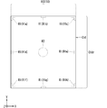
- FIG. 4 is a front view of the video display module 100 according to the first embodiment. As described above, as an example, the display area 10 exists in the entire image display module 100 in a plan view. Therefore, FIG. 4 is also a front view of the display area 10. As described above, the shape of the image display module 100 in plan view is the same as the shape of the display area 10 in plan view.
- Each region R1 is a part of the image display module 100.
- the eight fixed portions 11 of the fixed region Ch1r corresponding to the video display module 100 come into contact with the back surface of the video display module 100.
- Each region R1 is a region of the video display module 100 that is in contact with the housing Ch1. That is, each region R1 also includes the back side of the video display module 100. Therefore, the housing Ch1 is in contact with a part of the video display module 100.
- the non-contact region is a region of the video display module 100 that is different from the region R1. That is, each region R1 and a non-contact region exist in the display region 10 (video display module 100) in a plan view.
- the central portion of the image display module 100 in a plan view is also referred to as a “reference portion”, a “region R2”, or a “R2”.
- the region R2 as a reference portion is the region shown in FIG.
- the region R2 is a part of the non-contact region.
- Each region R1 has a specific heat dissipation characteristic.
- the non-contact region has a heat dissipation characteristic different from that of each region R1. That is, the heat dissipation characteristics of each region R1 are different from the heat dissipation characteristics of the non-contact region (for example, region R2). Specifically, the thermal conductivity of each region R1 is larger than the thermal conductivity of the non-contact region (for example, region R2).
- each region R1 of the video display module 100 comes into contact with the fixed portion 11 of the housing Ch1 made of metal. Therefore, due to heat conduction, the heat of the image display module 100 is dissipated via the housing Ch1. Therefore, in the video display module 100, the temperature of each region R1 is lower than the temperature of the non-contact region. Therefore, in a situation where the temperature of each region R1 and the temperature of the non-contact region are different, if the temperature-corresponding luminance correction process described later is not performed, luminance unevenness may occur.
- Each region R1 corresponds to one fixed portion 11 included in the eight fixed portions 11 of the fixed region Ch1r.
- Each region R1 is a region of the video display module 100 that is in contact with one fixed portion 11 corresponding to the region R1.
- the eight regions R1 are also referred to as "regions R1a, R1b, R1c, R1d, R1e, R1f, R1g, R1h".
- the regions R1a, R1b, R1c, R1d, R1e, R1f, R1g, and R1h correspond to the fixed portions 11a, 11b, 11c, 11d, 11e, 11f, 11g, and 11h, respectively.
- the region R1a is a region of the video display module 100 that is in contact with the fixed portion 11a of the housing Ch1.
- the number of fixed portions 11 provided in one fixed region Ch1r in the housing Ch1 is not limited to 8, and may be any value from 1 to 7 or 9 or more.
- FIG. 5 is a block diagram showing the configuration of the video display module 100 according to the first embodiment.
- the image display module 100 includes a drive unit 30, a display unit 50, and a temperature measurement unit 40.
- the display unit 50 has the display screen of the display area 10 described above.
- the display screen of the display area 10 is composed of a plurality of LEDs 5 as pixels. That is, in the display area 10, a plurality of LEDs 5 as pixels for displaying an image are arranged. The plurality of LEDs 5 are arranged in a matrix.
- the image display module 100 displays an image on the display screen of the display area 10 by controlling the light emission of each LED.
- the display screen of the display area 10 is configured by arranging k pixels (LED5) in a matrix of, for example, 270 rows and 320 columns.
- K is a natural number of 2 or more.
- "k” is a value obtained by the formula of 320 ⁇ 270. That is, the display screen of the display area 10 is composed of 320 ⁇ 270 pixels.
- the display screen of the above-mentioned multi-display area 10A is configured by arranging m pixels (LED5) in a matrix.
- M is a natural number of 4 or more.
- M is a value obtained by the formula of k ⁇ 4.
- m is a value obtained by the formula of 320 ⁇ 270 ⁇ 4.
- each LED 5 constituting the display screen of the display area 10 includes three sub-pixels.
- the three sub-pixels are LEDs 5sr, 5sg, and 5sb, respectively.
- the luminosity of an LED changes under the influence of the atmospheric temperature of the LED.
- the atmospheric temperature of the LED is the temperature of the air existing around the LED.
- FIG. 6 is a graph showing the characteristics of the LED.
- the graph of FIG. 6 shows the relationship between the atmospheric temperature of the LED and the relative luminous intensity.
- the vertical axis indicates the relative luminous intensity
- the horizontal axis indicates the atmospheric temperature of the LED.
- the lower the atmospheric temperature of the LED the higher the luminosity of the LED. That is, the higher the atmospheric temperature of the LED, the lower the luminosity of the LED.
- each of red, green and blue is also referred to as "primary color”. Further, in the following, red, green and blue are also referred to as R, G and B, respectively. Further, in the following, red light, green light and blue light are also referred to as R light, G light and B light, respectively.
- the LEDs 5sr, 5sg, and 5sb emit R light, G light, and B light, respectively. That is, each of the LEDs 5sr, 5sg, and 5sb as sub-pixels is an element for expressing different primary colors. In the following, each of R light, G light, and B light is also referred to as "primary color light”. Further, in the following, the luminous intensity of R light, the luminous intensity of G light, and the luminous intensity of B light are also referred to as R luminous intensity, G luminous intensity, and B luminous intensity, respectively. That is, the R luminous intensity is the luminous intensity of the LED 5sr. The G luminous intensity is the luminous intensity of LED 5sg. The B luminous intensity is the luminous intensity of the LED 5sb.
- each of the LEDs 5sr, 5sg, and 5sb is also referred to as "LED5s".
- the display screen of the display area 10 is composed of (k ⁇ 3) LEDs 5s.
- the LED 5 emits a combination of red light, green light, and blue light emitted by the LEDs 5sr, 5sg, and 5sb (hereinafter, also referred to as “synthetic light”).
- synthetic light the luminous intensity of the synthetic light emitted by the LED 5 is also referred to as “the luminous intensity of the LED 5”.
- the coefficient used for correcting the luminous intensity of the LEDs 5s is also referred to as a “correction coefficient”. That is, the correction coefficient is a coefficient used to correct the luminous intensity of the LEDs 5s (LED5).
- the coefficient for suppressing the luminance variation and the chromaticity variation in the image display module 100 is also referred to as a “variation correction coefficient”.
- the image to be displayed on the entire display screen of the multi-display area 10A is also referred to as "image Im".
- the image Im is represented by an R image, a G image, and a B image.
- the resolutions of the R image, the G image, and the B image are the same.
- the R image is an image of the red component in the image Im.
- the G image is an image of the green component in the image Im.
- the B image is an image of the blue component in the image Im.
- the image Im is represented by four different partial images as an example.
- Each partial image is an image for display by any of the four image display modules 100.
- Each video display module 100 displays a partial video corresponding to the video display module 100 on the display screen of the display area 10.
- the image display modules 100-1, 100-2, 100-3, and 100-4 display four partial images, respectively, so that the image Im is displayed on the entire display screen of the multi-display area 10A.
- the drive unit 30 drives the display unit 50 so that the image is displayed on the display unit 50 (display screen of the display area 10).
- the drive unit 30 drives the display unit 50 by, for example, a PWM (Pulse Width Modulation) method.
- PWM Pulse Width Modulation
- the temperature measuring unit 40 has a function of measuring the temperature.
- the temperature measuring unit 40 has a function of measuring the temperature of a plurality of parts of the image display module 100.
- the temperature measuring unit 40 includes a reference unit temperature sensor 42 and eight correction unit temperature sensors 41.
- the number of the correction unit temperature sensors 41 included in the temperature measurement unit 40 is not limited to 8, and may be any value from 1 to 7 or 9 or more.
- the area R1 is also referred to as a "correction unit”. That is, eight correction units (area R1) exist in the display area 10 of the video display module 100.
- the temperature of the region R1 as the correction unit is also referred to as “correction unit temperature T1”, “correction unit temperature”, “temperature T1” or “T1”.
- the correction unit temperature T1 is, for example, the atmospheric temperature of the LED 5 existing in the region R1.
- the temperature of the region R2 as the reference portion is also referred to as “reference portion temperature T2”, “reference portion temperature”, “temperature T2” or “T2”.
- the reference portion temperature T2 is the temperature in the non-contact region. Further, the reference portion temperature T2 is, for example, the atmospheric temperature of the LED 5 existing in the region R2 as the reference portion.
- the reference unit temperature sensor 42 has a function of measuring the reference unit temperature T2 in the region R2 of the image display module 100.
- the reference portion temperature sensor 42 is provided, for example, in the region R2 of FIG.
- the reference unit temperature sensor 42 is provided, for example, in the region R2 on the back surface side of the image display module 100.
- the reference unit temperature sensor 42 transmits the reference unit temperature information indicating the measured reference unit temperature T2 to the control module 200.
- Each of the eight correction unit temperature sensors 41 corresponds to the eight correction units (region R1).
- Each correction unit temperature sensor 41 has a function of measuring the correction unit temperature T1 of the correction unit (region R1) corresponding to the correction unit temperature sensor 41. That is, each region R1 (correction unit) is a region in which the correction unit temperature T1 is measured by each correction unit temperature sensor 41 of the temperature measurement unit 40.
- Each correction unit temperature sensor 41 transmits the correction unit temperature information indicating the correction unit temperature T1 measured by the correction unit temperature sensor 41 to the control module 200.
- the eight correction unit temperature sensors 41 are also referred to as "correction unit temperature sensors 41a, 41b, 41c, 41d, 41e, 41f, 41g, 41h".
- the correction unit temperature sensors 41a, 41b, 41c, 41d, 41e, 41f, 41g, 41h correspond to the regions R1a, R1b, R1c, R1d, R1e, R1f, R1g, and R1h, respectively.
- the correction unit temperature sensors 41a, 41b, 41c, 41d, 41e, 41f, 41g, 41h are provided in the regions a1, a2, a3, a4, a5, a6, a7, a8, respectively.
- the correction unit temperature sensor 41a is provided in the region a1 of FIG.
- the correction unit temperature sensor 41a has a function of measuring the temperature T1 of the region R1a as the correction unit.
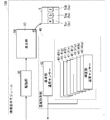
- FIG. 7 is a block diagram showing the configuration of the control module 200 according to the first embodiment.
- the control module 200 includes an input terminal 21, a brightness correction unit 220, a video division unit 230, a correction coefficient specifying unit 250, a temperature information acquisition unit 260, and a variation correction coefficient storage unit 271.
- a temperature correction coefficient storage unit 272 is provided.
- the input terminal 21 receives a video signal from the outside.
- the video signal is a signal including video data indicating video Im to be displayed on the display screen of the multi-display area 10A.
- the video signal is transmitted to the luminance correction unit 220.
- the brightness correction unit 220 corrects the brightness of the image Im indicated by the image data included in the image signal, although the details will be described later.
- the luminance correction unit 220 transmits the corrected image Im to the image division unit 230.
- the video dividing unit 230 divides the received video Im into four different partial videos described above. Then, the video dividing unit 230 transmits the four partial videos to the video display modules 100-1, 100-2, 100-3, and 100-4, respectively.
- the temperature information acquisition unit 260 acquires the correction unit temperature information indicating the correction unit temperature T1 from each correction unit temperature sensor 41. Further, the temperature information acquisition unit 260 acquires the reference unit temperature information indicating the reference unit temperature T2 from the reference unit temperature sensor 42. The temperature information acquisition unit 260 transmits the acquired correction unit temperature information and reference unit temperature information to the correction coefficient specifying unit 250.
- a plurality of variation correction coefficients are stored in the variation correction coefficient storage unit 271.
- the plurality of variation correction coefficients are coefficients for reducing the variation in the luminous intensity of the LED 5 in the image display module 100.
- Each variation correction coefficient shows, for example, a value for reducing the luminance variation and the chromaticity variation in the image display module 100.
- a value adjusted in advance by the operator in the adjustment process is set for each variation correction coefficient before the image display device 1000 (image display module 100) as a product is shipped from the factory. Has been done.
- the operator uses a measuring instrument to measure and correct the R luminous intensity, the G luminous intensity, and the B luminous intensity in each pixel (LED5) included in the display unit 50, thereby correcting each variation.
- the value of the coefficient is adjusted.
- the variation correction coefficient storage unit 271 of each video display module 100 included in the display unit 500 stores each variation correction coefficient individually adjusted for the video display module 100.
- the position of the pixel in the horizontal direction on the display screen of the multi-display area 10A is also referred to as "position x”.
- "X” is a natural number of 1 or more.
- the position of the pixel in the vertical direction on the display screen of the multi-display area 10A is also referred to as “position y”.
- "Y” is a natural number of 1 or more.
- the coordinates (positions) of the pixels on the display screen of the multi-display area 10A are expressed as “coordinates xy", “coordinates (x, y)” or "(x, y)”.
- the pixel (LED5) specified by the coordinates xy on the display screen of the multi-display area 10A is also referred to as “pixel Pxy” or “pixel P (x, y)”.
- the variation correction coefficient for correcting the R luminous intensity of the pixel Pxy (LED5) is also referred to as “variation correction coefficient CDRxy” or “CDRxy”.
- the variation correction coefficient for correcting the G luminous intensity of the pixel Pxy (LED5) is also referred to as “variation correction coefficient CDGxy” or “CDGxy”.
- the variation correction coefficient for correcting the B luminous intensity of the pixel Pxy (LED5) is also referred to as “variation correction coefficient CDBxy” or “CDBxy”.
- the number of each of the variation correction coefficients CDRxy, CDGxy, and CDBxy stored in the variation correction coefficient storage unit 271 is m.
- each temperature correction coefficient is a characteristic coefficient used in the present embodiment.
- the difference between the temperature of the correction unit and the temperature of the non-contact region is also referred to as “regional temperature difference”.
- the temperature of the non-contact region is, for example, the reference portion temperature.
- the region temperature difference is, for example, the difference between the correction unit temperature and the reference unit temperature.
- the luminous intensity of the LED existing in the region R1 as the correction unit is also referred to as “correction unit luminous intensity”.
- the luminous intensity of the LED existing in the non-contact region is also referred to as “non-correction portion luminous intensity”.
- the uncorrected portion luminous intensity is, for example, the luminous intensity of the LED existing in the region R2.
- the difference between the luminous intensity of the corrected portion and the luminous intensity of the non-corrected portion is also referred to as “temperature-compatible luminous intensity difference”.
- the region temperature difference is not 0, there is a temperature-corresponding luminous intensity difference. If there is a temperature-corresponding luminous intensity difference corresponding to the area temperature difference, luminance unevenness occurs on the display screen of the display area 10 included in the multi-display area 10A.
- each region R1 as the correction unit is lower than the temperature of the non-contact region.
- Each temperature correction coefficient is a coefficient for correcting the temperature-corresponding luminous intensity difference.
- each temperature correction coefficient is a coefficient for reducing the temperature-corresponding luminous intensity difference and reducing the luminance unevenness.
- the temperature correction coefficient corresponding to the LED 5sr is also referred to as “temperature correction coefficient CTR” or “CTR”.
- the temperature correction coefficient CTR is a coefficient corresponding to the LED 5sr as a sub pixel.
- the temperature correction coefficient corresponding to the LED 5sg is also referred to as “temperature correction coefficient CTG” or “CTG”.
- the temperature correction coefficient CTG is a coefficient corresponding to the LED 5sg as a sub pixel.
- the temperature correction coefficient corresponding to the LED 5sb is also referred to as “temperature correction coefficient CTB” or “CTB”.
- the temperature correction coefficient CTB is a coefficient corresponding to the LED 5sb as a sub pixel.
- the difference between the correction unit temperature T1 and the reference unit temperature T2 is also referred to as “temperature difference ⁇ T” or “ ⁇ T”.
- the temperature difference ⁇ T is expressed by the following equation (1).
- FIG. 8 is a diagram showing a plurality of temperature correction coefficients stored in the temperature correction coefficient storage unit 272.
- a table Tb1 showing the plurality of temperature correction coefficients is shown. That is, the table Tb1 is stored in the temperature correction coefficient storage unit 272.
- the correction unit temperature T1 is 25 ° C. and the reference unit temperature T2 is 28 ° C.
- each temperature correction coefficient shown by the table Tb1 is a coefficient for reducing the temperature-corresponding luminous intensity difference and reducing the luminance unevenness.
- Each temperature correction coefficient shown in the table Tb1 is determined, for example, by repeating the adjustment operation.
- the adjustment work includes, for example, changing the temperature difference ⁇ T by adjusting the temperature of the correction unit temperature T1 and the temperature of the reference unit T2, adjusting the values of the temperature correction coefficients CTR, CTG, and CTB, performing the temperature-compatible luminance correction processing described later, and the temperature. It is the measurement of R light intensity, G light intensity, B light intensity, etc. in the situation where the corresponding luminance correction process is carried out.
- the correction coefficient specifying unit 250 has a function of specifying the luminance correction coefficient C, although details will be described later.
- the luminance correction coefficient C is a coefficient for correcting the luminance of the image Im.
- the above-mentioned temperature correction coefficient is a coefficient for specifying the luminance correction coefficient C.
- the luminance correction coefficient C for correcting the R luminous intensity of the pixel Pxy (LED5) is also referred to as “luminance correction coefficient CRxy” or “CRxy”.
- the luminance correction coefficient C for correcting the G luminous intensity of the pixel Pxy (LED5) is also referred to as “luminance correction coefficient CGxy” or “CGxy”.
- the luminance correction coefficient C for correcting the B luminous intensity of the pixel Pxy (LED5) is also referred to as “luminance correction coefficient CBxy” or “CBxy”.
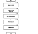
- FIG. 9 is a flowchart of the temperature-compatible luminance correction process according to the first embodiment.
- FIG. 9 shows only the main steps included in the temperature-compatible luminance correction process.
- the temperature-based luminance correction process performed under the following premise Pm1 will be described.
- the video Im is also referred to as the "target video”.
- the target image is an image to be displayed in the multi-display area 10A (display screen). That is, the target image is an image to be displayed in the display area 10 (display screen).
- the pixel of the target image is also referred to as “target pixel”.
- the target pixel is a pixel represented by the pixel Pxy (LED5). That is, the target pixel is a pixel corresponding to the pixel Pxy.
- the variation correction coefficient storage unit 271 stores the variation correction coefficients CDRxy, CDGxy, and CDBxy corresponding to each target pixel (each pixel Pxy).
- the target image includes m target pixels.
- "m” is a value obtained by the formula of k ⁇ 4.
- the target pixel is composed of a plurality of sub-pixels for expressing different primary colors.
- the target pixel is composed of R pixels, G pixels, and B pixels as sub-pixels.
- the R pixel is a sub-pixel of the R component.
- the G pixel is a sub-pixel of the G component.
- the B pixel is a sub-pixel of the B component.
- the R pixel is a pixel represented by the LED 5sr.
- the G pixel is a pixel represented by the LED 5sg.
- the B pixel is a pixel represented by the LED 5sb.
- the target video (video Im) is represented by an R image, a G image, and a B image.
- the R image of the target image is composed of m R pixels.
- the G image of the target video is composed of m G pixels.
- the B image of the target video is composed of m B pixels.
- the control module 200 receives a video signal including video data indicating the video Im as the target video. Further, in the premise Pm1, the correction unit temperature T1 is 25 ° C. Further, in the premise Pm1, the reference portion temperature T2 is 28 ° C.
- the temperature measurement process is performed (step S110).
- the temperature measurement unit 40 of each video display module 100 measures the correction unit temperature T1 and the reference unit temperature T2.
- each correction unit temperature sensor 41 of the temperature measurement unit 40 included in each video display module 100 measures the correction unit temperature T1 of the correction unit (region R1) corresponding to the correction unit temperature sensor 41.
- Each correction unit temperature sensor 41 transmits the correction unit temperature information indicating the measured correction unit temperature T1 to the temperature information acquisition unit 260 of the control module 200.
- the reference unit temperature sensor 42 of the temperature measurement unit 40 included in each video display module 100 measures the reference unit temperature T2 of the region R2 of the video display module 100.
- the reference unit temperature sensor 42 included in each video display module 100 transmits the reference unit temperature information indicating the measured reference unit temperature T2 to the temperature information acquisition unit 260 of the control module 200.
- the correction coefficient specifying unit 250 of the control module 200 has eight correction units from each of the video display modules 100-1, 100-2, 100-3, and 100-4 via the temperature information acquisition unit 260. Receives temperature information and reference unit temperature information.
- the temperature correction coefficient specifying process is performed (step S120).
- the correction coefficient specifying unit 250 specifies the temperature correction coefficient based on the correction unit temperature T1 indicated by each correction unit temperature information and the reference unit temperature T2 indicated by the reference unit temperature information. That is, the temperature correction coefficient is a coefficient based on the correction unit temperature T1 and the reference unit temperature T2.
- the eight correction unit temperatures T1 indicated by the eight correction unit temperature information corresponding to each video display module 100 are the same temperature.
- the reference portion temperature T2 indicated by the reference portion temperature information corresponding to each video display module 100 is the same temperature.
- the correction unit temperature T1 is 25 ° C. and the reference unit temperature T2 is 28 ° C.
- the correction coefficient specifying process is performed (step S130).
- the correction coefficient specifying unit 250 specifies the luminance correction coefficient C.
- the luminance correction coefficient C is a coefficient for performing the luminance correction process described later.
- the luminance correction process is a process based on the correction unit temperature T1 and the reference unit temperature T2. Further, the luminance correction process is a process of correcting the luminance of the target pixel of the target image (image Im).
- the correction coefficient specifying unit 250 specifies three luminance correction coefficients C (CRxy, CGxy, CBxy) corresponding to each of the m target pixels included in the target image.
- the pixels for displaying in the area R1 are also referred to as “temperature correction pixels”.
- the pixels for displaying in the non-contact area are also referred to as “non-temperature correction pixels”.
- the correction coefficient specifying unit 250 specifies the luminance correction coefficient C based on the specified temperature correction coefficient.
- the correction coefficient specifying unit 250 uses the following equations (2-1), equation (2-2), and equation (2-3).
- the brightness correction coefficients CRxy, CGxy, and CBxy are specified by the variation correction coefficients CDRxy, CDGxy, and CDBxy corresponding to the target pixel, and the specified temperature correction coefficients CTR, CTG, and CTB.
- Luminance correction coefficients CRxy, CGxy, and CBxy are coefficients for correcting the brightness of the target pixel of the target image. Further, as described above, the temperature correction coefficients CTR, CTG, and CTB are coefficients for reducing the temperature-corresponding luminous intensity difference and reducing the luminance unevenness. Therefore, the luminance correction coefficients CRxy, CGxy, and CBxy specified by the equations (2-1), (2-2), and (2-3) reduce the temperature-corresponding luminous intensity difference and reduce the luminance unevenness. It is also a coefficient of.
- the luminance correction coefficients CRxy, CGxy, and CBxy are coefficients for correcting the luminance of the R pixel, the G pixel, and the B pixel, respectively.
- Each of the R pixel, G pixel, and B pixel is a sub-pixel of the target pixel.
- the correction coefficient specifying unit 250 when the target pixel is a non-temperature correction pixel, the correction coefficient specifying unit 250 includes the following equations (3-1), equations (3-2) and equations (3-3).
- the brightness correction coefficients CRxy, CGxy, and CBxy are specified by the variation correction coefficients CDRxy, CDGxy, and CDBxy corresponding to the target pixel. That is, when the target pixel is a non-temperature correction pixel, the correction coefficient specifying unit 250 specifies the variation correction coefficients CDRxy, CDGxy, and CDBxy corresponding to the target pixels as the luminance correction coefficients CRxy, CGxy, and CBxy.
- the correction coefficient specifying unit 250 performs the above processing in order to specify the luminance correction coefficient C for each of the m target pixels included in the target image.
- the correction coefficient specifying unit 250 specifies three luminance correction coefficients C (CRxy, CGxy, CBxy) corresponding to each of the m target pixels included in the target image. That is, the correction coefficient specifying unit 250 specifies m luminance correction coefficients CRxy, m luminance correction coefficients CGxy, and m luminance correction coefficients CBxy. All the specified luminance correction coefficients C are coefficients for reducing the luminance unevenness based on the temperature-corresponding luminous intensity difference.
- the video display device 1000 performs the luminance correction process based on the specified luminance correction coefficient C (step S140).
- the luminance correction unit 220 of the control module 200 corrects the luminance of the target pixel of the target image.
- the brightness of the target pixel is corrected by multiplying the brightness (gradation value) of the target pixel of the target image by the brightness correction coefficient C.
- the luminance correction coefficient C corresponding to the temperature correction pixel is a coefficient based on the temperature correction coefficients CTR, CTG, and CTB. Therefore, the luminance correction process is a process based on the temperature correction coefficients CTR, CTG, and CTB.
- the luminance correction unit 220 has, for example, m for each of the gradation values (pixel values) of m R pixels constituting the R image of the target image which is the image Im. Multiplies the luminance correction factor CRxy of. As a result, a corrected R image is obtained.
- a corrected target image R image, G image, B image
- the target image obtained by the luminance correction process is also referred to as “corrected target image” or “corrected image Im”.
- the state of the image in the situation where the image is displayed on the display screen of the multi-display area 10A is also referred to as “display state”.
- the corrected target image (image Im) is an image for reducing the temperature-corresponding luminous intensity difference in the situation where the temperature-corresponding luminous intensity difference exists. That is, the corrected target image (image Im) is an image in which the luminance unevenness based on the temperature-corresponding luminous intensity difference is reduced in the image Im in the displayed state. Therefore, by displaying the corrected target image (image Im), the luminous intensity of the LED is corrected so that the luminance unevenness is reduced.
- the luminance correction unit 220 transmits the corrected image Im to the image division unit 230.
- the video dividing unit 230 divides the corrected video Im into the four different partial videos described above. Then, the video dividing unit 230 transmits the four partial videos to the video display modules 100-1, 100-2, 100-3, and 100-4, respectively.
- the video display process is performed (step S150).
- the video display modules 100-1, 100-2, 100-3, and 100-4 display four partial videos, respectively.
- the drive unit 30 of each video display module 100 drives the display unit 50 so that the received partial image is displayed on the display screen of the display area 10 in the display unit 50.
- the display unit 50 drives a plurality of LEDs 5.
- the corrected video Im is displayed on the entire display screen of the multi-display area 10A.
- the target image (image Im) whose display state has been corrected is an image in which the luminance unevenness based on the temperature-corresponding luminous intensity difference is reduced even in a situation where there is a temperature-corresponding luminous intensity difference corresponding to the region temperature difference.
- the temperature-compatible luminance correction process is completed.
- a plurality of LEDs 5 are arranged in the display area 10.
- the display area 10 has an area R1 and an area R2.
- the correction coefficient specifying unit 250 specifies a luminance correction coefficient for performing the luminance correction process.
- the image display device 1000 performs a luminance correction process for correcting the luminance of the pixels of the image to be displayed in the display area 10 based on the luminance correction coefficient.
- the luminance correction process is a process based on the correction section temperature T1 in the region R1 and the reference section temperature T2 in the region R2.
- the heat dissipation characteristic of the region R1 is different from the heat dissipation characteristic of the region R2.
- processing is performed to correct the brightness of the pixels of the image to be displayed in the display area in consideration of the temperature of the plurality of areas having different heat dissipation characteristics existing in the display area in which the plurality of LEDs are arranged. Can be done.
- the corrected target image for reducing the temperature-corresponding luminous intensity difference (Video Im) is generated.
- the corrected target image (image Im) By displaying the corrected target image (image Im), the luminous intensity of the LED is corrected so that the temperature-corresponding luminous intensity difference becomes small. Therefore, even in a situation where the correction unit temperature T1 is lower than the reference unit temperature T2, it is possible to reduce the luminance unevenness based on the temperature-corresponding luminous intensity difference. That is, it is possible to reduce the luminance unevenness based on the temperature difference between the region R1 and the non-contact region.
- the luminance correction process is performed based on the temperature correction coefficients CTR, CTG, and CTB corresponding to the LEDs 5sr, 5sg, and 5sb as sub-pixels, respectively. Therefore, even when the "luminance-temperature characteristics" of the LEDs 5sr, 5sg, and 5sb are different, appropriate brightness correction processing can be performed. This makes it possible to reduce color unevenness based on the temperature difference between the region R1 and the non-contact region.
- the correction unit temperature sensor 41 is provided in each of the plurality of correction units of the video display module 100, but the configuration is not limited to this.
- the correction unit temperature sensor 41 is provided only in the one correction unit. May be good.
- the correction unit temperature T1 measured by the correction unit temperature sensor 41 is regarded as a representative temperature in the temperatures of the plurality of correction units. This makes it possible to reduce the number of temperature sensors provided in the image display module 100. Therefore, it is possible to provide a cheaper image display device 1000.
- the luminosity of an LED is affected by the atmospheric temperature of the LED.
- the lower the atmospheric temperature of the LED the higher the luminosity of the LED.
- the luminosity of each pixel is corrected by using the correction coefficient calculated based on the luminosity of each pixel measured in advance. In this case, it may not be possible to correct the difference in luminosity caused by the environment in which the display device is actually used, the temperature difference in a plurality of parts of the display device, and the like.
- the housing contact area is an area of the video display module that is in contact with a part of the housing.
- the video display module includes, for example, a substrate on which an LED is mounted. Therefore, the temperature of the housing contact region tends to be lower than the temperature of the region different from the housing contact region. As a result, there is a problem that luminance unevenness occurs due to the temperature difference between the housing contact region and the portion different from the housing contact region.
- the video display device 1000 of the present embodiment has a configuration for achieving the above effects. Therefore, the video display device 1000 of the present embodiment can solve the above problem.
- ⁇ Modification 1> The configuration of this modification is applied to the first embodiment.
- overcorrection or undercorrection may occur due to variations in thermal resistance between the temperature sensor 41 of the correction unit and the LED existing in the region R1 (correction unit). ..
- the overcorrection is a correction in which the amount of correction of the luminous intensity (luminance) is too large.
- Insufficient correction is a correction in which the amount of correction of luminous intensity (luminance) is insufficient.
- overcorrection or insufficient correction occurs, a situation occurs in which reduction of luminance unevenness, color unevenness, etc. is not sufficient.
- the configuration of this modification is to improve the situation where the reduction of luminance unevenness, color unevenness, etc. is not sufficient due to overcorrection or insufficient correction.
- the configuration of this modification is such that when the reduction of luminance unevenness, color unevenness, etc. is not sufficient, the correction amount is adjusted by an external operation to sufficiently reduce the luminance unevenness, color unevenness, etc. Is.
- the video display device 1000 according to the first modification has a different configuration of the control module 200 than the video display device 1000 according to the first embodiment. Since the other configurations of the video display device 1000 according to the first modification are the same as those of the video display device 1000 according to the first embodiment, detailed description thereof will not be repeated.
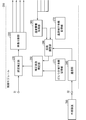
- FIG. 10 is a block diagram showing the configuration of the control module 200 according to the first modification.
- FIG. 10 shows an external device 700, which is not included in the video display device 1000, for the sake of explanation.
- the external device 700 is, for example, a PC (Personal Computer).
- the external device 700 may be an information processing device other than the PC.
- control module 200 according to the first modification has a communication terminal 22, a communication unit 240, and a coefficient adjusting unit 290 as compared with the control module 200 of FIG. 7 according to the first embodiment. Further prepare. Since the other configurations of the control module 200 according to the first modification are the same as those of the control module 200 according to the first embodiment, detailed description thereof will not be repeated.
- the communication terminal 22 is, for example, a terminal according to a standard such as LAN or RS-232C.
- the communication terminal 22 is connected to the external device 700 via a communication cable.
- the external device 700 is operated by an operator.
- the communication unit 240 communicates with the external device 700 via the communication terminal 22.
- the coefficient adjusting unit 290 is a component for adjusting the temperature correction coefficient, although the details will be described later. Although the details will be described later, the coefficient adjusting unit 290 adjusts the effect of correcting the brightness of the pixel (that is, the luminous intensity of the LED) by adjusting the temperature correction coefficient.
- the temperature information acquisition unit 260 transmits the correction unit temperature information and the reference unit temperature information received from each video display module 100 to the coefficient adjustment unit 290.
- FIG. 11 is a flowchart of the temperature-compatible luminance correction process A according to the first modification.
- FIG. 11 shows only the main steps included in the temperature-compatible luminance correction process A.
- the process of the same step number as the step number of FIG. 9 is the same as the process described in the first embodiment, and therefore the detailed description is not repeated.
- the difference between the temperature-compatible luminance correction process A and the temperature-compatible luminance correction process of the first embodiment will be mainly described.
- the temperature-corresponding luminance correction process A performed under the following premise Pm2 will be described.
- Premise Pm2 includes the above-mentioned premise Pm1. Further, in the premise Pm2, the external device 700 transmits the coefficient adjustment instruction to the video display device 1000.
- the coefficient adjustment instruction is an instruction for adjusting the temperature correction coefficient. Specifically, the coefficient adjustment instruction is an instruction for causing the video display device 1000 to adjust the temperature correction coefficient.
- the coefficient adjustment value A is indicated in the coefficient adjustment instruction.
- the coefficient adjustment value A is an adjustment value for adjusting the temperature correction coefficient. That is, the coefficient adjustment value A is an adjustment value for adjusting the correction amount (correction amount of luminous intensity) of the temperature-corresponding luminous intensity difference.
- the coefficient adjustment value A for adjusting the temperature correction coefficient CTR is also referred to as “coefficient adjustment value AR” or “AR”.
- the coefficient adjustment value A for adjusting the temperature correction coefficient CTG is also referred to as “coefficient adjustment value AG” or “AG”.
- the coefficient adjustment value A for adjusting the temperature correction coefficient CTB is also referred to as “coefficient adjustment value AB” or “AB”.
- the coefficient adjustment values AR, AG, and AB are indicated.
- Each of the coefficient adjustment values AR, AG, and AB is a real number larger than 0.
- the coefficient adjustment instruction transmission process is first performed (step S101A).
- the external device 700 transmits the coefficient adjustment instruction to the communication unit 240 of the control module 200 via the communication terminal 22.
- the coefficient adjustment instruction indicates the coefficient adjustment values AR, AG, and AB.
- the communication unit 240 receives the coefficient adjustment instruction from the external device 700.
- the communication unit 240 transmits the coefficient adjustment instruction to the coefficient adjustment unit 290.
- the coefficient adjustment unit 290 receives the coefficient adjustment instruction indicating the coefficient adjustment values AR, AG, and AB.
- the temperature measurement process in step S110 is performed in the same manner as in the first embodiment.
- the temperature information acquisition unit 260 of the control module 200 has eight correction unit temperature information and reference unit temperature information from each of the video display modules 100-1, 100-2, 100-3, and 100-4.
- the coefficient adjusting unit 290 of the control module 200 has eight correction unit temperature information from each of the video display modules 100-1, 100-2, 100-3, and 100-4 via the temperature information acquisition unit 260. , And the reference unit temperature information is received.
- the temperature correction coefficient specifying process A is performed (step S120A).
- the coefficient adjusting unit 290 specifies the temperature correction coefficient based on the correction unit temperature T1 indicated by each correction unit temperature information and the reference unit temperature T2 indicated by the reference unit temperature information.
- the conditions for specifying the temperature correction coefficient are the same as those in the first embodiment in order to make the explanation easy to understand. That is, it is assumed that the eight correction unit temperatures T1 indicated by the eight correction unit temperature information corresponding to each video display module 100 are the same temperature. Further, it is assumed that the reference portion temperature T2 indicated by the reference portion temperature information corresponding to each video display module 100 is the same temperature. Further, it is assumed that the correction unit temperature T1 is 25 ° C. and the reference unit temperature T2 is 28 ° C.
- the correction coefficient adjustment process A is performed (step S125A).
- the coefficient adjustment unit 290 adjusts the temperature correction coefficient based on the coefficient adjustment instructions (coefficient adjustment values AR, AG, AB).
- the adjusted temperature correction coefficient is also referred to as “adjusted temperature correction coefficient”.
- the adjusted temperature correction coefficient CTR is also referred to as “adjusted temperature correction coefficient CTRA” or “CTRA”.
- the adjusted temperature correction coefficient CTG is also referred to as “adjusted temperature correction coefficient CTG” or “CTGa”.
- the adjusted temperature correction coefficient CTB is also referred to as “adjusted temperature correction coefficient CTBa” or “CTBa”.
- the coefficient adjustment unit 290 is based on the following equations (4-1), equations (4-2) and (4-3), temperature correction coefficients CTR, CTG, CTB, and coefficient adjustment values AR, AG, AB. , The adjusted temperature correction coefficients CTRa, CTGa, CTBa are specified. Then, the coefficient adjusting unit 290 transmits the specified adjustment temperature correction coefficients CTRa, CTGa, CTBa to the correction coefficient specifying unit 250.
- CTRa CTR according to the equation (4-1).
- CTGa and CTBa are the same as CTRa.
- CTGa and CTBa are the same as CTRa.
- CTRa the closer the CTRa becomes to "1".
- CTRa is "0.9976", which is close to "1", according to the formula (4-1).
- CTGa and CTBa are the same as CTRa.
- the correction coefficient specifying process A is performed (step S130A).
- the correction coefficient specifying process A is the same as the correction coefficient specifying process of FIG.
- the correction coefficient specifying process A has a different formula for specifying the luminance correction coefficients CRxy, CGxy, and CBxy as compared with the correction coefficient specifying process.
- the points different from the correction coefficient specifying process in the correction coefficient specifying process A will be mainly described.
- the correction coefficient specifying unit 250 specifies the luminance correction coefficient C.
- the correction coefficient specifying unit 250 specifies three luminance correction coefficients C (CRxy, CGxy, CBxy) corresponding to each of the m target pixels included in the target image.
- the correction coefficient specifying unit 250 specifies the brightness correction coefficient C based on the adjusted temperature correction coefficient which is the adjusted temperature correction coefficient. Specifically, in the correction coefficient specifying process A, when the target pixel is a temperature correction pixel, the correction coefficient specifying unit 250 uses the following equations (5-1), equation (5-2) and equation (5-3). ), The variation correction coefficients CDRxy, CDGxy, CDBxy corresponding to the target pixel, and the adjustment temperature correction coefficients CTRa, CTGa, CTBa specify the brightness correction coefficients CRxy, CGxy, CBxy.
- the correction of the brightness of the target pixel using the luminance correction coefficients CGxy and CBxy is the same as the correction of the luminance of the target pixel using the luminance correction coefficient CRxy.
- the luminance correction coefficient CRxy when the target pixel is a temperature correction pixel is expressed by the following equation (6-1). Further, according to the equations (4-2) and (5-2), and the equations (4-3) and (5-3), the luminance correction coefficients CGxy and CBxy when the target pixel is a temperature correction pixel can be determined. , Expressed by the following equations (6-2) and (6-3).
- the correction coefficient specifying unit 250 is based on the above equations (3-1), (3-2) and (3-3). , The luminance correction coefficients CRxy, CGxy, and CBxy are specified.
- the correction coefficient specifying unit 250 performs the above processing in order to specify the luminance correction coefficient C for each of the m target pixels included in the target image.
- the correction coefficient specifying unit 250 specifies three luminance correction coefficients C (CRxy, CGxy, CBxy) corresponding to each of the m target pixels included in the target image.
- step S140 the luminance correction process of step S140 is performed in the same manner as in the first embodiment.
- step S150 the video display process of step S150 is performed in the same manner as in the first embodiment.
- the temperature-corresponding luminance correction process A in the premise Pm2 is completed. That is, in the temperature-corresponding luminance correction process A in the premise Pm2, when the communication unit 240 of the control module 200 receives the coefficient adjustment instruction from the external device 700, the above-mentioned correction coefficient adjustment process A (S125A) and the correction coefficient specifying process A (S130A) is performed.
- the temperature-compatible luminance correction process A of this modification is performed as described above. Therefore, when there is insufficient correction, in the temperature-corresponding luminance correction process A, each of the coefficient adjustment values AR, AG, and AB is set to a value larger than 1. As a result, the lack of correction can be improved. Further, when there is overcorrection, in the temperature-corresponding luminance correction process A, each of the coefficient adjustment values AR, AG, and AB is set to a value smaller than 1. Thereby, the overcorrection can be improved.
- the effect of luminance (luminosity) correction can be adjusted by an external device. can. Therefore, in a situation where the reduction of luminance unevenness, color unevenness, etc. is not sufficient, the luminance unevenness, color unevenness, etc. can be sufficiently reduced.
- FIG. 12 is a block diagram showing a characteristic functional configuration of the video display device BL10.
- the video display device BL10 corresponds to the video display device 1000. That is, FIG. 12 is a block diagram showing the main functions related to the present technology among the functions of the video display device BL10.
- the video display device BL10 has a display area for displaying video.
- the video display device BL10 functionally includes a temperature measuring unit BL1 and a correction coefficient specifying unit BL2.
- the temperature measuring unit BL1 has a function of measuring the temperature.
- the temperature measuring unit BL1 corresponds to the temperature measuring unit 40.
- the display region includes a first region having a first heat dissipation characteristic and a second region having a second heat dissipation characteristic different from the first heat dissipation characteristic.
- the temperature measuring unit BL1 measures the first temperature, which is the temperature of the first region, and the second temperature, which is the temperature of the second region.
- the correction coefficient specifying unit BL2 specifies the brightness correction coefficient for performing the brightness correction process based on the first temperature and the second temperature.
- the correction coefficient specifying unit BL2 corresponds to the correction coefficient specifying unit 250.
- the luminance correction process is a process of correcting the luminance of the pixels of the target image, which is the image to be displayed in the display area.
- the image display device BL10 performs the luminance correction process for correcting the luminance of the target pixel, which is a pixel of the target image, based on the specified luminance correction coefficient.
- the video display device according to the present technology has been described above based on the embodiment, but the present technology is not limited to the embodiment.
- the present technology also includes modifications that can be conceived by those skilled in the art to the extent that they do not deviate from the gist of the present technology. That is, the embodiments and modifications can be freely combined, and the embodiments and modifications can be appropriately modified or omitted.
- the video display module 100 does not have to include all the components shown in the figure. That is, the video display module 100 may include only the minimum components that can realize the effect of the present technology.
- each function of the temperature measuring unit 40 and the correction coefficient specifying unit 250 included in the image display device 1000 may be realized by a processing circuit.
- the processing circuit is a circuit for measuring a first temperature, which is the temperature of the first region existing in the display region, and a second temperature, which is the temperature of the second region existing in the display region. ..
- the first heat dissipation characteristic of the first region is different from the second heat dissipation characteristic of the second region.
- the processing circuit is also a circuit for specifying a luminance correction coefficient for performing a luminance correction process based on the first temperature and the second temperature.
- the processing circuit may be dedicated hardware. Further, the processing circuit may be a processor that executes a program stored in the memory.
- the processor is, for example, a CPU (Central Processing Unit), a central processing unit, an arithmetic unit, a microprocessor, a microcomputer, a DSP (Digital Signal Processor), or the like.
- configuration Cs1 the configuration in which the processing circuit is dedicated hardware
- configuration Cs2 the configuration in which the processing circuit is a processor
- configuration Cs3 a configuration in which each function of the temperature measuring unit 40 and the correction coefficient specifying unit 250 is realized by a combination of hardware and software is also referred to as “configuration Cs3”.
- the processing circuit is, for example, a single circuit, a composite circuit, a programmed processor, a parallel programmed processor, an ASIC (Application Specific Integrated Circuit), an FPGA (Field Programmable Gate Array), or a combination thereof.
- ASIC Application Specific Integrated Circuit
- FPGA Field Programmable Gate Array
- the functions of the temperature measuring unit 40 and the correction coefficient specifying unit 250 may be realized by two processing circuits, respectively. Further, all the functions of the temperature measuring unit 40 and the correction coefficient specifying unit 250 may be realized by one processing circuit.
- the configuration in which all or part of each component included in the video display device 1000 is shown by hardware is as follows, for example.
- a video display device in which all or a part of each component included in the video display device 1000 is shown by hardware is also referred to as a “video display device hd10”.
- FIG. 13 is a hardware configuration diagram of the video display device hd10.
- the video display device hd10 includes a processor hd1 and a memory hd2.
- the memory hd2 is, for example, a non-volatile or volatile semiconductor memory such as a RAM (RandomAccessMemory), a ROM (ReadOnlyMemory), a flash memory, an EPROM, or an EEPROM.
- the memory hd2 is, for example, a magnetic disk, a flexible disk, an optical disk, a compact disk, a mini disk, a DVD, or the like. Further, the memory hd2 may be any storage medium used in the future.
- the processing circuit is the processor hd1.
- each function of the temperature measuring unit 40 and the correction coefficient specifying unit 250 is realized by software, firmware, or a combination of software and firmware.
- the software or firmware is described as a program and stored in the memory hd2.
- the processing circuit (processor hd1) reads the program stored in the memory hd2 and executes the program, whereby the functions of the temperature measuring unit 40 and the correction coefficient specifying unit 250 are realized.
- the memory hd2 stores the following programs.
- the program performs a step of measuring a first temperature, which is the temperature of the first region existing in the display region, and a second temperature, which is the temperature of the second region existing in the display region, as a processing circuit (a process unit). It is a program to be executed by the processor hd1).
- the first heat dissipation characteristic of the first region is different from the second heat dissipation characteristic of the second region.
- the program is also a program for causing the processing circuit (processor hd1) to execute a step of specifying a luminance correction coefficient for performing a luminance correction process based on the first temperature and the second temperature.
- the program also causes a computer to execute a procedure of processing performed by each of the temperature measuring unit 40 and the correction coefficient specifying unit 250, a method of executing the processing, and the like.
- the function of the temperature measuring unit 40 is realized by the processing circuit reading and executing the program stored in the memory.
- the function of the correction coefficient specifying unit 250 is realized by a processing circuit as dedicated hardware.
- the processing circuit can realize each of the above-mentioned functions by hardware, software, firmware, or a combination thereof.
- the present technology may be realized as a luminance correction method in which the operation of a characteristic component included in the video display device 1000 is a step. Further, the present technology may be realized as a program for causing a computer to execute each step included in such a luminance correction method. Further, the present technology may be realized as a computer-readable recording medium for storing such a program. Further, the program may be distributed via a transmission medium such as the Internet.
- the luminance correction method according to the present technology corresponds to, for example, the processing of FIG. 9 or FIG.
- the number of video display modules 100 included in the display unit 500 is not limited to an integer of 2 or more, and may be 1.
- the temperature measuring unit 40 does not have to be included in the video display module 100. That is, the temperature measuring unit 40 may be provided outside the video display module 100.
- the correction coefficient specifying unit 250 may be configured to further perform the processing performed by the coefficient adjusting unit 290 in addition to the processing described in the embodiment. In this configuration, the coefficient adjusting unit 290 is unnecessary. Further, in the configuration, the temperature information acquisition unit 260 transmits the correction unit temperature information and the reference unit temperature information received from each video display module 100 to the correction coefficient specifying unit 250. Further, in the configuration, the communication unit 240 transmits the coefficient adjustment instruction to the correction coefficient specifying unit 250.
Landscapes
- Engineering & Computer Science (AREA)
- Physics & Mathematics (AREA)
- Computer Hardware Design (AREA)
- General Physics & Mathematics (AREA)
- Theoretical Computer Science (AREA)
- Control Of Indicators Other Than Cathode Ray Tubes (AREA)
- Control Of El Displays (AREA)
Abstract
表示領域10には、複数のLED5が配列されている。表示領域10には、領域R1と領域R2とが存在する。補正係数特定部250は、輝度補正処理を行うための輝度補正係数を特定する。映像表示装置1000は、輝度補正係数に基づいて、表示領域10に表示するための映像の画素の輝度を補正する輝度補正処理を行う。輝度補正処理は、領域R1の補正部温度T1および領域R2の基準部温度T2に基づいた処理である。領域R1が有する放熱特性は、領域R2が有する放熱特性と異なる。
Description
本開示は、複数のLED(Light Emitting Diode)を有する映像表示装置および輝度補正方法に関する。
LEDを有するLED表示装置は、LEDの技術発展および低コスト化に伴い、屋外または屋内における広告表示等のために使用される機会が増えつつある。これまで、LED表示装置は、自然画、アニメーション等の動画像を表示することが主であった。
しかし、近年、屋内用途のLED表示装置において、画素ピッチの狭ピッチ化が進んでいる。そのため、屋内用途のLED表示装置の視認距離が短くなっている。これにより、屋内用途としての、会議室用途、監視用途等のためにLED表示装置が使用されている。特に、監視用途のLED表示装置が、例えば、静止画に近いパソコン画像を表示することが多くなっている。
LED表示装置が有する複数のLEDの光度特性には、ばらつきが存在する。そのため、LED表示装置の表示面に輝度ムラ等が発生する。特許文献1では、輝度ムラを低減するための構成(以下、「関連構成A」ともいう)が開示されている。関連構成Aでは、画素としての各LEDの光度が、補正係数に基づいて補正される。これにより、表示面における各LEDの光度特性の均一化が実現されている。
LED表示装置のような映像表示装置は、複数のLEDが配列されている表示領域であって、かつ、映像を表示するための表示領域を有する。当該表示領域において放熱特性の異なる複数の領域が存在する構成を有する映像表示装置も存在する。当該映像表示装置では、表示領域に表示される映像の品質の低下を抑制するために、当該表示領域に表示するための映像の画素の輝度を補正する処理であって、かつ、当該複数の領域の温度を考慮した処理を行うことが要求される。関連構成Aでは、この要求を満たすことはできない。
本開示は、このような問題を解決するためになされたものであり、複数のLEDが配列されている表示領域に存在する、放熱特性の異なる複数の領域の温度を考慮した、当該表示領域に表示するための映像の画素の輝度を補正する処理を行うことが可能な映像表示装置等を提供することを目的とする。
上記目的を達成するために、本開示の一態様に係る映像表示装置は、映像を表示するための表示領域を有する。前記映像表示装置は、温度を計測する機能を有する温度計測部を備え、前記表示領域には、前記映像を表示するための画素としての複数のLED(Light Emitting Diode)が配列されており、前記表示領域には、第1放熱特性を有する第1領域と、前記第1放熱特性と異なる第2放熱特性を有する第2領域とが存在し、前記温度計測部は、前記第1領域の温度である第1温度、および、前記第2領域の温度である第2温度を計測し、前記映像表示装置は、さらに、前記第1温度および前記第2温度に基づいた輝度補正処理を行うための輝度補正係数を特定する補正係数特定部を備え、前記輝度補正処理は、前記表示領域に表示するための前記映像である対象映像の画素の輝度を補正する処理であり、前記映像表示装置は、特定された前記輝度補正係数に基づいて、前記対象映像の画素である対象画素の輝度を補正する前記輝度補正処理を行う。
本開示によれば、表示領域には、複数のLEDが配列されている。前記表示領域には、第1領域と第2領域とが存在する。補正係数特定部は、輝度補正処理を行うための輝度補正係数を特定する。映像表示装置は、前記輝度補正係数に基づいて、前記表示領域に表示するための映像の画素の輝度を補正する前記輝度補正処理を行う。前記輝度補正処理は、前記第1領域の第1温度および前記第2領域の第2温度に基づいた処理である。前記第1領域が有する第1放熱特性は、前記第2領域が有する第2放熱特性と異なる。
これにより、複数のLEDが配列されている表示領域に存在する、放熱特性の異なる複数の領域の温度を考慮した、当該表示領域に表示するための映像の画素の輝度を補正する処理を行うことができる。
本開示の目的、特徴、局面、および利点は、以下の詳細な説明と添付図面とによって、より明白となる。
以下、図面を参照しつつ、実施の形態について説明する。以下の図面では、同一の構成要素には同一の符号を付してある。同一の符号が付されている構成要素の名称および機能は同じである。したがって、同一の符号が付されている構成要素の一部についての詳細な説明を省略する場合がある。
なお、実施の形態において例示される構成要素の寸法、材質、形状、当該構成要素の相対配置などは、装置の構成、各種条件等により適宜変更されてもよい。また、図における構成要素の寸法は、実際の寸法と異なる場合がある。
<実施の形態1>
図1は、実施の形態1に係る映像表示装置1000の構成を示す図である。映像表示装置1000は、表示素子としてのLEDを使用して映像を表示するLED表示装置である。
図1は、実施の形態1に係る映像表示装置1000の構成を示す図である。映像表示装置1000は、表示素子としてのLEDを使用して映像を表示するLED表示装置である。
図1において、X方向、Y方向およびZ方向は、互いに直交する。以下の図に示されるX方向、Y方向およびZ方向も、互いに直交する。以下においては、X方向と、当該X方向の反対の方向(-X方向)とを含む方向を「X軸方向」ともいう。また、以下においては、Y方向と、当該Y方向の反対の方向(-Y方向)とを含む方向を「Y軸方向」ともいう。また、以下においては、Z方向と、当該Z方向の反対の方向(-Z方向)とを含む方向を「Z軸方向」ともいう。
また、以下においては、X軸方向およびY軸方向を含む平面を、「XY面」ともいう。また、以下においては、X軸方向およびZ軸方向を含む平面を、「XZ面」ともいう。また、以下においては、Y軸方向およびZ軸方向を含む平面を、「YZ面」ともいう。
図1に示すように、映像表示装置1000は、表示ユニット500と、制御モジュール200とを備える。表示ユニット500は、4台の映像表示モジュール100と、筐体Ch1とを含む。4台の映像表示モジュール100の各々の構成および形状は、同じである。各映像表示モジュール100の形状は、板状である。各映像表示モジュール100は、例えば、LEDモジュールである。各映像表示モジュール100は、例えば、LEDが実装されている基板を含むモジュールである。なお、表示ユニット500に含まれる映像表示モジュール100の数は、4に限定されず、2、または、6以上の整数であってもよい。
平面視における各映像表示モジュール100には、映像を表示するための表示領域10が存在する。すなわち、4台の映像表示モジュール100の各々は、表示領域10を有する。表示領域10は、平面視における映像表示モジュール100のうち、映像を表示するための領域である。表示領域10の前面側は、映像を表示するための画面である。
平面視における表示ユニット500には、マルチ表示領域10Aが存在する。平面視におけるマルチ表示領域10Aの形状は、例えば、矩形である。マルチ表示領域10Aは、複数の映像表示モジュール100が、それぞれ有する複数の表示領域10が行列状に配置されて構成される1つの領域である。マルチ表示領域10Aの前面側は、映像を表示するための画面である。以下においては、表示領域10の画面、または、マルチ表示領域10Aの画面を、「表示画面」ともいう。なお、マルチ表示領域10Aを構成する表示領域10の数は、4に限定されず、2、または、6以上の整数であってもよい。
各映像表示モジュール100の表示領域10は、一例として、平面視における当該映像表示モジュール100の全体に存在する。平面視における映像表示モジュール100の形状は、平面視における表示領域10の形状と同じである。
表示ユニット500では、4台の映像表示モジュール100が、一例として、図1のように、2行2列の行列状に配置される。以下においては、表示ユニット500に含まれる4台の映像表示モジュール100を、「映像表示モジュール100-1,100-2,100-3,100-4」とも表記する。
筐体Ch1は、映像表示モジュール100-1,100-2,100-3,100-4を保持する。すなわち、映像表示モジュール100-1,100-2,100-3,100-4は、筐体Ch1に固定される。筐体Ch1の詳細については後述する。
以下においては、映像表示モジュール100が筐体Ch1に固定されている状況における、当該映像表示モジュール100の状態を、「固定状態」ともいう。また、以下においては、映像表示モジュール100が筐体Ch1に固定されていない状況における、当該映像表示モジュール100の状態を、「非固定状態」ともいう。
映像表示モジュール100-1,100-2,100-3,100-4の各々は、制御モジュール200と通信可能に構成されている。制御モジュール200は、表示ユニット500に含まれる映像表示モジュール100-1,100-2,100-3,100-4の各々と通信する。
制御モジュール200は、映像表示モジュール100-1,100-2,100-3,100-4を制御する。制御モジュール200は、各映像表示モジュール100に、例えば、映像信号、制御信号等を送信することによって、表示ユニット500のマルチ表示領域10Aに映像を表示させる機能を有する。
図2は、実施の形態1に係る表示ユニット500の概略構成を示す分解斜視図である。また、図2では、筐体Ch1の構造を分かりやすくするために、非固定状態の映像表示モジュール100-2が示される。すなわち、図2では、筐体Ch1から映像表示モジュール100-2が分離されている状態が示される。また、図2では、各映像表示モジュール100を筐体Ch1に固定するための構造物等は示されていない。
筐体Ch1は、高い放熱性を有する。筐体Ch1は、金属で構成される。筐体Ch1は、例えば、金属製フレームである。
以下においては、筐体Ch1のうち、1台の映像表示モジュール100が固定されるための領域を、「固定領域Ch1r」ともいう。筐体Ch1は、4つの固定領域Ch1rを有する。4つの固定領域Ch1rは、それぞれ、映像表示モジュール100-1,100-2,100-3,100-4に対応する。
図3は、図2の一部の拡大図である。図3では、筐体Ch1のうち、映像表示モジュール100-2に対応する1つの固定領域Ch1rに対応する部分が示される。図3に示すように、筐体Ch1における当該1つの固定領域Ch1rには、8個の固定部11が設けられる。
筐体Ch1は、固定領域Ch1rに対応する8個の固定部11を有する。8個の固定部11の各々は、筐体Ch1の一部である。すなわち、8個の固定部11の各々は、金属で構成される。固定領域Ch1rに対応する8個の固定部11は、映像表示モジュール100を筐体Ch1に固定するための部分である。以下においては、8個の固定部11を、「固定部11a,11b,11c,11d,11e,11f,11g,11h」とも表記する。
図3において、固定部11a,11b,11c,11d,11e,11f,11g,11hは、それぞれ、領域a1,a2,a3,a4,a5,a6,a7,a8に設けられる。例えば、固定部11aは、領域a1内に設けられる。ところで、図3において、固定部11fは、非固定状態の映像表示モジュール100-2の背面側に存在するため、当該固定部11fは、図3に示されていない。
図2において、映像表示モジュール100-1,100-3,100-4に対応する3つの固定領域Ch1rの各々の構成は、図3の固定領域Ch1rの構成と同様である。
映像表示モジュール100-1,100-2,100-3,100-4の状態が固定状態である状況では、当該映像表示モジュール100-1,100-2,100-3,100-4が、それぞれ、4つの固定領域Ch1rに固定される。これにより、映像表示モジュール100-1,100-2,100-3,100-4に、それぞれ対応する4つの表示領域10間の平坦度が確保される。
図4は、実施の形態1に係る映像表示モジュール100の正面図である。前述したように、表示領域10は、一例として、平面視における当該映像表示モジュール100の全体に存在する。そのため、図4は、表示領域10の正面図でもある。前述したように、平面視における映像表示モジュール100の形状は、平面視における表示領域10の形状と同じである。
平面視における映像表示モジュール100の表示領域10には、8個の領域R1が存在する。各領域R1は、映像表示モジュール100の一部である。映像表示モジュール100の状態が固定状態である状況では、当該映像表示モジュール100に対応する固定領域Ch1rの8個の固定部11は、当該映像表示モジュール100の背面に接触する。各領域R1は、映像表示モジュール100のうち、筐体Ch1と接触している領域である。すなわち、各領域R1は、映像表示モジュール100の背面側も含む。そのため、筐体Ch1は、映像表示モジュール100の一部と接触している。
以下においては、映像表示モジュール100のうち、筐体Ch1と接触していない領域を、「非接触領域」ともいう。非接触領域は、映像表示モジュール100のうち、領域R1と異なる領域である。すなわち、平面視における表示領域10(映像表示モジュール100)には、各領域R1と、非接触領域とが存在する。
また、以下においては、平面視における映像表示モジュール100の中心部を、「基準部」、「領域R2」または「R2」ともいう。基準部としての領域R2は、図4に示される領域である。領域R2は、非接触領域の一部である。
各領域R1は、特定の放熱特性を有する。非接触領域は、各領域R1の放熱特性と異なる放熱特性を有する。すなわち、各領域R1が有する放熱特性は、非接触領域(例えば、領域R2)が有する放熱特性と異なる。具体的には、各領域R1の熱伝導率は、非接触領域(例えば、領域R2)の熱伝導率より大きい。
映像表示モジュール100の状態が固定状態である状況では、当該映像表示モジュール100の各領域R1は、金属で構成される筐体Ch1の固定部11と接触する。そのため、熱伝導により、映像表示モジュール100の熱が、筐体Ch1を介して、放散される。したがって、映像表示モジュール100において、各領域R1の温度は、非接触領域の温度より低い。そのため、各領域R1の温度と非接触領域の温度とが異なる状況において、仮に、後述の温度対応輝度補正処理が行われない場合、輝度ムラが発生する可能性がある。
各領域R1は、固定領域Ch1rの8個の固定部11に含まれる1個の固定部11に対応する。各領域R1は、映像表示モジュール100のうち、当該領域R1に対応する1個の固定部11と接触している領域である。
以下においては、8個の領域R1を、「領域R1a,R1b,R1c,R1d,R1e,R1f,R1g,R1h」とも表記する。領域R1a,R1b,R1c,R1d,R1e,R1f,R1g,R1hは、それぞれ、固定部11a,11b,11c,11d,11e,11f,11g,11hに対応する。例えば、領域R1aは、映像表示モジュール100のうち、筐体Ch1の固定部11aと接触している領域である。
なお、筐体Ch1における1つの固定領域Ch1rに設けられる固定部11の数は、8に限定されず、1から7のいずれかの値、または、9以上であってもよい。
次に、映像表示モジュール100の構成について説明する。図5は、実施の形態1に係る映像表示モジュール100の構成を示すブロック図である。図5に示すように、映像表示モジュール100は、駆動部30と、表示部50と、温度計測部40とを備える。
表示部50は、前述の表示領域10の表示画面を有する。表示領域10の表示画面は、画素としての複数のLED5で構成される。すなわち、表示領域10には、映像を表示するための画素としての複数のLED5が配列されている。当該複数のLED5は、行列状に配列されている。映像表示モジュール100は、各LEDに対し、発光の制御を行うことにより、表示領域10の表示画面に映像を表示する。
表示領域10の表示画面は、k個の画素(LED5)が、例えば、270行320列の行列状に配置されることにより構成される。「k」は、2以上の自然数である。「k」は、一例として、320×270の式で得られる値である。すなわち、表示領域10の表示画面は、320×270画素で構成される。
前述のマルチ表示領域10Aの表示画面は、m個の画素(LED5)が、行列状に配置されることにより構成される。「m」は、4以上の自然数である。「m」は、k×4の式で得られる値である。「m」は、一例として、320×270×4の式で得られる値である。また、表示領域10の表示画面を構成する各前記LED5は、3つのサブ画素を含む。当該3つのサブ画素は、それぞれ、LED5sr,5sg,5sbである。
次に、LEDの特性について説明する。LEDの光度は、当該LEDの雰囲気温度の影響を受けて、変化する。LEDの雰囲気温度は、当該LEDの周囲に存在する空気の温度である。図6は、LEDの特性を示すグラフである。図6のグラフは、LEDの雰囲気温度と、相対光度との関係を示す。図6において、縦軸は、相対光度を示し、横軸は、LEDの雰囲気温度を示す。図6のように、LEDの雰囲気温度が低い程、LEDの光度は高くなる。すなわち、LEDの雰囲気温度が高い程、LEDの光度は低くなる。
以下においては、赤、緑および青の各々を、「原色」ともいう。また、以下においては、赤、緑および青を、それぞれ、R、GおよびBともいう。また、以下においては、赤色光、緑色光および青色光を、それぞれ、R光、G光およびB光ともいう。
LED5sr,5sg,5sbは、それぞれ、R光、G光、B光を射出する。すなわち、サブ画素としてのLED5sr,5sg,5sbの各々は、異なる原色を表現するための素子である。以下においては、R光、G光およびB光の各々を、「原色光」ともいう。また、以下においては、R光の光度、G光の光度、および、B光の光度を、それぞれ、R光度、G光度、および、B光度ともいう。すなわち、R光度は、LED5srの光度である。また、G光度は、LED5sgの光度である。また、B光度は、LED5sbの光度である。
以下においては、LED5sr,5sg,5sbの各々を、「LED5s」ともいう。表示領域10の表示画面は、(k×3)個のLED5sで構成される。
再び、図5を参照して、LED5は、LED5sr,5sg,5sbがそれぞれ射出する赤色光、緑色光および青色光が合成された光(以下、「合成光」ともいう)を射出する。以下においては、LED5が射出する合成光の光度を、「LED5の光度」ともいう。
また、以下においては、LED5s(LED5)の光度の補正に使用するための係数を、「補正係数」ともいう。すなわち、補正係数は、LED5s(LED5)の光度を補正するために使用される係数である。以下においては、映像表示モジュール100における輝度ばらつきおよび色度ばらつきを抑制するための係数を、「ばらつき補正係数」ともいう。
また、以下においては、マルチ表示領域10Aの表示画面全体に表示するための映像を、「映像Im」ともいう。映像Imは、R画像、G画像およびB画像により表現される。R画像、G画像およびB画像の各々の解像度は、同じである。R画像は、映像Imにおける赤成分の画像である。G画像は、映像Imにおける緑成分の画像である。B画像は、映像Imにおける青成分の画像である。
以下においては、映像Imの一部を、「部分映像」ともいう。本実施の形態では、映像Imは、一例として、異なる4つの部分映像で表現される。各部分映像は、4台の映像表示モジュール100のいずれかが表示するための映像である。各映像表示モジュール100は、当該映像表示モジュール100に対応する部分映像を表示領域10の表示画面に表示する。映像表示モジュール100-1,100-2,100-3,100-4が、それぞれ、4つの部分映像を表示することにより、マルチ表示領域10Aの表示画面全体に映像Imが表示される。
駆動部30は、映像が表示部50(表示領域10の表示画面)に表示されるように、表示部50を駆動させる。駆動部30は、例えば、PWM(Pulse Width Modulation)方式により、表示部50を駆動させる。これにより、表示部50に含まれる各LED5のLED5sr,5sg,5sbの光度が制御される。
温度計測部40は、温度を計測する機能を有する。温度計測部40は、映像表示モジュール100における複数の部分の温度を計測する機能を有する。温度計測部40は、基準部温度センサー42と、8個の補正部温度センサー41とを含む。なお、温度計測部40に含まれる補正部温度センサー41の数は、8に限定されず、1から7のいずれかの値、または、9以上であってもよい。
以下においては、領域R1を、「補正部」ともいう。すなわち、映像表示モジュール100の表示領域10には、8個の補正部(領域R1)が存在する。以下においては、補正部としての領域R1の温度を、「補正部温度T1」、「補正部温度」、「温度T1」または「T1」ともいう。補正部温度T1は、例えば、領域R1に存在するLED5の雰囲気温度である。
また、以下においては、基準部としての領域R2の温度を、「基準部温度T2」、「基準部温度」、「温度T2」または「T2」ともいう。基準部温度T2は、非接触領域の温度である。また、基準部温度T2は、例えば、基準部としての領域R2に存在するLED5の雰囲気温度である。
基準部温度センサー42は、映像表示モジュール100の領域R2の基準部温度T2を計測する機能を有する。平面視において、基準部温度センサー42は、例えば、図4の領域R2内に設けられる。基準部温度センサー42は、例えば、映像表示モジュール100の背面側における領域R2に設けられる。基準部温度センサー42は、計測した基準部温度T2を示す基準部温度情報を制御モジュール200へ送信する。
8個の補正部温度センサー41は、それぞれ、8個の補正部(領域R1)に対応する。各補正部温度センサー41は、当該補正部温度センサー41に対応する補正部(領域R1)の補正部温度T1を計測する機能を有する。すなわち、各領域R1(補正部)は、温度計測部40の各補正部温度センサー41により補正部温度T1が計測される領域である。各補正部温度センサー41は、当該補正部温度センサー41が計測した補正部温度T1を示す補正部温度情報を制御モジュール200へ送信する。
以下においては、8個の補正部温度センサー41を、「補正部温度センサー41a,41b,41c,41d,41e,41f,41g,41h」とも表記する。補正部温度センサー41a,41b,41c,41d,41e,41f,41g,41hは、それぞれ、領域R1a,R1b,R1c,R1d,R1e,R1f,R1g,R1hに対応する。補正部温度センサー41a,41b,41c,41d,41e,41f,41g,41hは、それぞれ、領域a1,a2,a3,a4,a5,a6,a7,a8に設けられる。例えば、補正部温度センサー41aは、図3の領域a1内に設けられる。また、例えば、補正部温度センサー41aは、補正部としての領域R1aの温度T1を計測する機能を有する。
図7は、実施の形態1に係る制御モジュール200の構成を示すブロック図である。図7に示すように、制御モジュール200は、入力端子21と、輝度補正部220と、映像分割部230と、補正係数特定部250と、温度情報取得部260と、ばらつき補正係数記憶部271と、温度補正係数記憶部272とを備える。
入力端子21は、外部から映像信号を受信する。当該映像信号は、マルチ表示領域10Aの表示画面に表示するための映像Imを示す映像データを含む信号である。映像信号は、輝度補正部220へ送信される。
輝度補正部220は、詳細は後述するが、映像信号に含まれる映像データが示す映像Imの輝度を補正する。輝度補正部220は、補正された映像Imを、映像分割部230へ送信する。
映像分割部230は、受信した映像Imを、前述した異なる4つの部分映像に分割する。そして、映像分割部230は、当該4つの部分映像を、それぞれ、映像表示モジュール100-1,100-2,100-3,100-4へ送信する。
温度情報取得部260は、各補正部温度センサー41から、補正部温度T1を示す補正部温度情報を取得する。また、温度情報取得部260は、基準部温度センサー42から、基準部温度T2を示す基準部温度情報を取得する。温度情報取得部260は、取得した補正部温度情報および基準部温度情報を、補正係数特定部250へ送信する。
ばらつき補正係数記憶部271には、複数のばらつき補正係数が格納されている。当該複数のばらつき補正係数は、映像表示モジュール100におけるLED5の光度のばらつきを小さくするための係数である。各ばらつき補正係数は、例えば、映像表示モジュール100における輝度ばらつきおよび色度ばらつきを小さくするための値を示す。
これを実現するために、各ばらつき補正係数には、例えば、製品としての映像表示装置1000(映像表示モジュール100)が工場から出荷される前に、調整工程において作業者が予め調整した値が設定されている。調整工程では、例えば、作業者が、計測器を使用して、表示部50に含まれる各画素(LED5)における、R光度、G光度およびB光度の計測および補正を行うことにより、各ばらつき補正係数の値が調整される。
表示ユニット500に含まれる各映像表示モジュール100のばらつき補正係数記憶部271は、当該映像表示モジュール100に対し、個別に調整された各ばらつき補正係数を記憶している。
以下においては、マルチ表示領域10Aの表示画面における水平方向の画素の位置を、「位置x」ともいう。「x」は、1以上の自然数である。また、以下においては、マルチ表示領域10Aの表示画面における垂直方向の画素の位置を、「位置y」ともいう。「y」は、1以上の自然数である。また、以下においては、マルチ表示領域10Aの表示画面における、画素の座標(位置)を、「座標xy」、「座標(x,y)」または、「(x,y)」と表現する。また、以下においては、マルチ表示領域10Aの表示画面において、座標xyで特定される画素(LED5)を、「画素Pxy」または「画素P(x,y)」ともいう。
また、以下においては、画素Pxy(LED5)のR光度を補正するためのばらつき補正係数を、「ばらつき補正係数CDRxy」または「CDRxy」ともいう。また、以下においては、画素Pxy(LED5)のG光度を補正するためのばらつき補正係数を、「ばらつき補正係数CDGxy」または「CDGxy」ともいう。また、以下においては、画素Pxy(LED5)のB光度を補正するためのばらつき補正係数を、「ばらつき補正係数CDBxy」または「CDBxy」ともいう。ばらつき補正係数記憶部271に格納されている、ばらつき補正係数CDRxy,CDGxy,CDBxyの各々の数は、m個である。
また、温度補正係数記憶部272には、複数の温度補正係数が格納されている。各温度補正係数は、本実施の形態で使用される特徴的な係数である。以下においては、補正部温度と、非接触領域の温度との差を、「領域温度差」ともいう。非接触領域の温度は、例えば、基準部温度である。領域温度差は、例えば、補正部温度と基準部温度との差である。
また、以下においては、補正部としての領域R1に存在するLEDの光度を、「補正部光度」ともいう。また、以下においては、非接触領域に存在するLEDの光度を、「非補正部光度」ともいう。非補正部光度は、例えば、領域R2に存在するLEDの光度である。また、以下においては、補正部光度と非補正部光度との差を、「温度対応光度差」ともいう。
領域温度差が0でない場合、温度対応光度差は存在する。仮に、領域温度差に対応する温度対応光度差が存在する場合、マルチ表示領域10Aに含まれる表示領域10の表示画面において輝度ムラが発生する。
前述したように、補正部としての各領域R1の温度(補正部温度)は、非接触領域の温度より低い。この場合、領域温度差に対応する温度対応光度差が存在する。各温度補正係数は、温度対応光度差を補正するための係数である。具体的には、各温度補正係数は、温度対応光度差を小さくし、輝度ムラを低減するための係数である。
以下においては、LED5srに対応する温度補正係数を、「温度補正係数CTR」または「CTR」ともいう。温度補正係数CTRは、サブ画素としてのLED5srに対応する係数である。また、以下においては、LED5sgに対応する温度補正係数を、「温度補正係数CTG」または「CTG」ともいう。温度補正係数CTGは、サブ画素としてのLED5sgに対応する係数である。また、以下においては、LED5sbに対応する温度補正係数を、「温度補正係数CTB」または「CTB」ともいう。温度補正係数CTBは、サブ画素としてのLED5sbに対応する係数である。
また、以下においては、補正部温度T1と基準部温度T2との差を、「温度差ΔT」または「ΔT」ともいう。温度差ΔTは、以下の式(1)により表現される。

図8は、温度補正係数記憶部272に格納されている複数の温度補正係数を示す図である。図8では、当該複数の温度補正係数を示すテーブルTb1が示される。すなわち、温度補正係数記憶部272には、テーブルTb1が格納されている。
ここで、補正部温度T1が25℃であり、基準部温度T2が28℃であると仮定する。この場合、温度差ΔTは、式(1)により、ΔT=25-28=-3である。温度差ΔTが「-3」である場合、テーブルTb1により、CTR=0.976、CTG=0.978、CTB=0.977である。
テーブルTb1が示す各温度補正係数は、前述したように、温度対応光度差を小さくし、輝度ムラを低減するための係数である。テーブルTb1が示す各温度補正係数は、例えば、調整作業を繰り返し行うことにより、決定される。当該調整作業は、例えば、補正部温度T1および基準部温度T2の調整による温度差ΔTの変更、温度補正係数CTR,CTG,CTBの値の調整、後述の温度対応輝度補正処理の実施、当該温度対応輝度補正処理が実施された状況におけるR光度、G光度およびB光度の計測等である。
再び、図7を参照して、補正係数特定部250は、詳細は後述するが、輝度補正係数Cを特定する機能を有する。輝度補正係数Cは、映像Imの輝度を補正するための係数である。前述の温度補正係数は、輝度補正係数Cを特定するための係数である。
以下においては、画素Pxy(LED5)のR光度を補正するための輝度補正係数Cを、「輝度補正係数CRxy」または「CRxy」ともいう。また、以下においては、画素Pxy(LED5)のG光度を補正するための輝度補正係数Cを、「輝度補正係数CGxy」または「CGxy」ともいう。また、以下においては、画素Pxy(LED5)のB光度を補正するための輝度補正係数Cを、「輝度補正係数CBxy」または「CBxy」ともいう。
次に、映像表示装置1000が行う特徴的な処理である温度対応輝度補正処理について説明する。図9は、実施の形態1に係る温度対応輝度補正処理のフローチャートである。図9では、温度対応輝度補正処理に含まれる、主要なステップのみを示している。温度対応輝度補正処理の一例を分かりやすくするために、まず、以下の前提Pm1のもとで行われる温度対応輝度補正処理について説明する。
以下においては、映像Imを、「対象映像」ともいう。対象映像は、マルチ表示領域10A(表示画面)に表示するための映像である。すなわち、対象映像は、表示領域10(表示画面)に表示するための映像である。以下においては、対象映像の画素を、「対象画素」ともいう。対象画素は、画素Pxy(LED5)により表現される画素である。すなわち、対象画素は、画素Pxyに対応する画素である。対象画素(画素Pxy)は、複数存在する。ばらつき補正係数記憶部271には、各対象画素(各画素Pxy)に対応するばらつき補正係数CDRxy,CDGxy,CDBxyが格納されている。
対象映像は、m個の対象画素を含む。前述したように、「m」は、k×4の式で得られる値である。対象画素は、異なる原色を表現するための複数のサブ画素で構成される。具体的には、対象画素は、サブ画素としての、R画素、G画素およびB画素で構成される。R画素は、R成分のサブ画素である。G画素は、G成分のサブ画素である。B画素は、B成分のサブ画素である。R画素は、LED5srにより表現される画素である。G画素は、LED5sgにより表現される画素である。B画素は、LED5sbにより表現される画素である。
また、対象映像(映像Im)は、R画像、G画像およびB画像により表現される。対象映像のR画像は、m個のR画素で構成される。対象映像のG画像は、m個のG画素で構成される。対象映像のB画像は、m個のB画素で構成される。
前提Pm1では、制御モジュール200は、対象映像としての映像Imを示す映像データを含む映像信号を受信する。また、前提Pm1では、補正部温度T1は25℃である。また、前提Pm1では、基準部温度T2は28℃である。
図9参照して、前提Pm1における温度対応輝度補正処理では、まず、温度計測処理が行われる(ステップS110)。温度計測処理では、各映像表示モジュール100の温度計測部40が、補正部温度T1、および、基準部温度T2を計測する。
具体的には、各映像表示モジュール100に含まれる温度計測部40の各補正部温度センサー41が、当該補正部温度センサー41に対応する補正部(領域R1)の補正部温度T1を計測する。各補正部温度センサー41は、計測した補正部温度T1を示す補正部温度情報を制御モジュール200の温度情報取得部260へ送信する。
また、各映像表示モジュール100に含まれる温度計測部40の基準部温度センサー42は、当該映像表示モジュール100の領域R2の基準部温度T2を計測する。各映像表示モジュール100に含まれる基準部温度センサー42は、計測した基準部温度T2を示す基準部温度情報を制御モジュール200の温度情報取得部260へ送信する。
これにより、制御モジュール200の補正係数特定部250は、映像表示モジュール100-1,100-2,100-3,100-4の各々から、温度情報取得部260を介して、8個の補正部温度情報、および、基準部温度情報を受信する。
次に、温度補正係数特定処理が行われる(ステップS120)。温度補正係数特定処理では、補正係数特定部250が、各補正部温度情報が示す補正部温度T1、および、基準部温度情報が示す基準部温度T2に基づいて、温度補正係数を特定する。すなわち、温度補正係数は、補正部温度T1および基準部温度T2に基づいた係数である。
ここで、説明を分かりやすくするために、各映像表示モジュール100に対応する8個の補正部温度情報がそれぞれ示す8個の補正部温度T1は、同じ温度であると仮定する。また、各映像表示モジュール100に対応する基準部温度情報が示す基準部温度T2は、同じ温度であると仮定する。また、補正部温度T1が25℃であり、基準部温度T2が28℃であると仮定する。
この場合、温度差ΔTは、式(1)により、ΔT=25-28=-3である。温度差ΔTが「-3」である場合、補正係数特定部250は、図8のテーブルTb1により、CTR=0.976、CTG=0.978、および、CTB=0.977として、温度補正係数CTR,CTG,CTBを特定する。
次に、補正係数特定処理が行われる(ステップS130)。補正係数特定処理では、補正係数特定部250が、輝度補正係数Cを特定する。輝度補正係数Cは、後述の輝度補正処理を行うための係数である。当該輝度補正処理は、補正部温度T1および基準部温度T2に基づいた処理である。また、当該輝度補正処理は、対象映像(映像Im)の対象画素の輝度を補正する処理である。
補正係数特定処理では、補正係数特定部250が、対象映像に含まれるm個の対象画素の各々に対応する3個の輝度補正係数C(CRxy、CGxy、CBxy)を特定する。以下においては、領域R1に表示するための画素を、「温度補正画素」ともいう。また、以下においては、非接触領域に表示するための画素を、「非温度補正画素」ともいう。
対象画素が温度補正画素である場合、補正係数特定部250は、特定した温度補正係数に基づいて、輝度補正係数Cを特定する。
具体的には、補正係数特定処理では、対象画素が温度補正画素である場合、補正係数特定部250は、以下の式(2-1)、式(2-2)および式(2-3)と、対象画素に対応するばらつき補正係数CDRxy,CDGxy,CDBxyと、特定した温度補正係数CTR,CTG,CTBとにより、輝度補正係数CRxy、CGxy、CBxyを特定する。

輝度補正係数CRxy、CGxy、CBxyは、対象映像の対象画素の輝度を補正するための係数である。また、前述したように、温度補正係数CTR,CTG,CTBは、温度対応光度差を小さくし、輝度ムラを低減するための係数である。そのため、式(2-1)、式(2-2)および式(2-3)により特定される輝度補正係数CRxy、CGxy、CBxyは、温度対応光度差を小さくし、輝度ムラを低減するための係数でもある。
具体的には、輝度補正係数CRxy、CGxy、CBxyは、それぞれ、R画素、G画素およびB画素の輝度を補正するための係数である。R画素、G画素およびB画素の各々は、対象画素のサブ画素である。
また、補正係数特定処理では、対象画素が非温度補正画素である場合、補正係数特定部250は、以下の式(3-1)、式(3-2)および式(3-3)と、対象画素に対応するばらつき補正係数CDRxy,CDGxy,CDBxyとにより、輝度補正係数CRxy、CGxy、CBxyを特定する。すなわち、対象画素が非温度補正画素である場合、補正係数特定部250は、対象画素に対応するばらつき補正係数CDRxy,CDGxy,CDBxyを、輝度補正係数CRxy、CGxy、CBxyとして特定する。

補正係数特定部250は、対象映像に含まれるm個の対象画素の各々に対し、輝度補正係数Cを特定するために、上記の処理を行う。
以上のようにして、補正係数特定部250は、対象映像に含まれるm個の対象画素の各々に対応する3個の輝度補正係数C(CRxy、CGxy、CBxy)を特定する。すなわち、補正係数特定部250は、m個の輝度補正係数CRxyと、m個の輝度補正係数CGxyと、m個の輝度補正係数CBxyとを特定する。特定された全ての輝度補正係数Cは、温度対応光度差に基づく輝度ムラを低減するための係数である。
次に、映像表示装置1000は、特定された輝度補正係数Cに基づいて、輝度補正処理を行う(ステップS140)。輝度補正処理では、制御モジュール200の輝度補正部220が、対象映像の対象画素の輝度を補正する。
対象画素の輝度の補正は、対象映像の対象画素の輝度(階調値)に、輝度補正係数Cを乗じることによって行われる。温度補正画素に対応する輝度補正係数Cは、温度補正係数CTR,CTG,CTBに基づいた係数である。そのため、輝度補正処理は、温度補正係数CTR,CTG,CTBに基づいた処理である。
具体的には、輝度補正処理では、輝度補正部220が、例えば、映像Imである対象映像のR画像を構成するm個のR画素の階調値(画素値)に対し、それぞれ、m個の輝度補正係数CRxyを乗算する。これにより、補正されたR画像が得られる。このような処理が、R画像、G画像およびB画像に対し行われることにより、補正された対象映像(R画像、G画像、B画像)が得られる。
以下においては、輝度補正処理により得られる対象映像を、「補正された対象映像」または「補正された映像Im」ともいう。また、以下においては、マルチ表示領域10Aの表示画面に映像が表示された状況における、当該映像の状態を、「表示状態」ともいう。
補正された対象映像(映像Im)は、温度対応光度差が存在している状況において、温度対応光度差を小さくするための映像である。すなわち、補正された対象映像(映像Im)は、表示状態の当該映像Imにおいて温度対応光度差に基づく輝度ムラが低減される映像である。そのため、補正された対象映像(映像Im)が表示されることにより、当該輝度ムラが低減されるように、LEDの光度の補正が行われる。
輝度補正部220は、補正された映像Imを、映像分割部230へ送信する。映像分割部230は、補正された映像Imを、前述した異なる4つの部分映像に分割する。そして、映像分割部230は、当該4つの部分映像を、それぞれ、映像表示モジュール100-1,100-2,100-3,100-4へ送信する。
次に、映像表示処理が行われる(ステップS150)。映像表示処理では、映像表示モジュール100-1,100-2,100-3,100-4が、それぞれ、4つの部分映像を表示する。具体的には、各映像表示モジュール100の駆動部30が、受信した部分映像が、表示部50における表示領域10の表示画面に表示されるように、当該表示部50を駆動させる。当該表示部50は、複数のLED5を駆動させる。
これにより、マルチ表示領域10Aの表示画面全体に、補正された映像Imが表示される。表示状態の補正された対象映像(映像Im)は、領域温度差に対応する温度対応光度差が存在する状況でも、当該温度対応光度差に基づく輝度ムラが低減された映像である。以上により、温度対応輝度補正処理が終了する。
以上説明したように、本実施の形態によれば、表示領域10には、複数のLED5が配列されている。表示領域10には、領域R1と領域R2とが存在する。補正係数特定部250は、輝度補正処理を行うための輝度補正係数を特定する。映像表示装置1000は、輝度補正係数に基づいて、表示領域10に表示するための映像の画素の輝度を補正する輝度補正処理を行う。輝度補正処理は、領域R1の補正部温度T1および領域R2の基準部温度T2に基づいた処理である。領域R1が有する放熱特性は、領域R2が有する放熱特性と異なる。
これにより、複数のLEDが配列されている表示領域に存在する、放熱特性の異なる複数の領域の温度を考慮した、当該表示領域に表示するための映像の画素の輝度を補正する処理を行うことができる。
また、本実施の形態によれば、補正部温度T1が基準部温度T2より低く、温度対応光度差が存在している状況において、温度対応光度差を小さくするための、補正された対象映像(映像Im)が生成される。当該補正された対象映像(映像Im)が表示されることにより、当該温度対応光度差が小さくなるように、LEDの光度の補正が行われる。そのため、補正部温度T1が基準部温度T2より低い状況でも、温度対応光度差に基づく輝度ムラを低減することができる。すなわち、領域R1および非接触領域における温度差に基づく輝度ムラを低減することができる。
また、本実施の形態によれば、サブ画素としてのLED5sr,5sg,5sbにそれぞれ対応する温度補正係数CTR,CTG,CTBに基づいた輝度補正処理が行われる。そのため、LED5sr,5sg,5sbの「光度-温度特性」が異なる場合でも、適切な輝度補正処理を行うことができる。これにより、領域R1および非接触領域における温度差に基づく色ムラを低減することができる。
ところで、本実施の形態では、映像表示モジュール100の複数の補正部の各々に補正部温度センサー41を設ける構成としたが、この構成に限定されない。複数の補正部に含まれる1つの補正部の温度を、当該複数の補正部の温度における代表的な温度とみなすことができる場合、当該1つの補正部にのみ補正部温度センサー41が設けられてもよい。この場合、当該補正部温度センサー41が計測した補正部温度T1が、複数の補正部の温度における代表的な温度とみなされる。これにより、映像表示モジュール100に設けるための温度センサーの数を少なくすることができる。そのため、より安価な映像表示装置1000を提供することができる。
ところで、前述したように、LEDの光度は、当該LEDの雰囲気温度の影響を受ける。例えば、LEDの雰囲気温度が低い程、LEDの光度は高くなる。前述の関連構成Aでは、予め測定された各画素の光度に基づいて算出された補正係数を使用して、各画素の光度が補正される。この場合、表示装置が実際に使用される環境、当該表示装置の複数の部分における温度差等により生じる光度差を補正できない場合がある。
特に、筐体接触領域においては、映像表示モジュールの熱が筐体を介して、放散される。当該筐体接触領域は、映像表示モジュールのうち、筐体の一部と接触している領域である。映像表示モジュールは、例えば、LEDが実装されている基板を含む。そのため、筐体接触領域の温度は、筐体接触領域と異なる領域の温度より低くなる傾向がある。これにより筐体接触領域と当該筐体接触領域と異なる部分とにおける温度差により輝度ムラが発生するという問題がある。
そこで、本実施の形態の映像表示装置1000は、上記の効果を奏するための構成を有する。そのため、本実施の形態の映像表示装置1000により、上記の問題を解決することができる。
<変形例1>
本変形例の構成は、実施の形態1に適用される。実施の形態1の映像表示装置では、補正部温度センサー41と、領域R1(補正部)に存在するLEDとの間の熱抵抗のばらつきなどにより、過補正または補正不足が発生する可能性がある。過補正とは、光度(輝度)の補正量が多すぎる補正である。補正不足は、光度(輝度)の補正量が不足している補正である。過補正または補正不足が発生した場合、輝度ムラ、色ムラ等の低減が十分でない状況が発生する。
本変形例の構成は、実施の形態1に適用される。実施の形態1の映像表示装置では、補正部温度センサー41と、領域R1(補正部)に存在するLEDとの間の熱抵抗のばらつきなどにより、過補正または補正不足が発生する可能性がある。過補正とは、光度(輝度)の補正量が多すぎる補正である。補正不足は、光度(輝度)の補正量が不足している補正である。過補正または補正不足が発生した場合、輝度ムラ、色ムラ等の低減が十分でない状況が発生する。
本変形例の構成は、過補正または補正不足により、輝度ムラ、色ムラ等の低減が十分でない状況を改善するための構成である。具体的には、本変形例の構成は、輝度ムラ、色ムラ等の低減が十分でない場合、外部からの操作によって、補正量を調整して、輝度ムラ、色ムラ等を十分に低減する構成である。
変形例1に係る映像表示装置1000は、実施の形態1に係る映像表示装置1000と比較して、制御モジュール200の構成が異なる。変形例1に係る映像表示装置1000におけるその他の構成は、実施の形態1に係る映像表示装置1000と同様なので詳細な説明は繰り返さない。
図10は、変形例1に係る制御モジュール200の構成を示すブロック図である。図10には、説明のために、映像表示装置1000に含まれない、外部装置700が示される。外部装置700は、例えば、PC(Personal Computer)である。なお、外部装置700は、PC以外の情報処理装置であってもよい。
図10に示すように、変形例1に係る制御モジュール200は、実施の形態1に係る図7の制御モジュール200と比較して、通信端子22と、通信部240と、係数調整部290とをさらに備える。変形例1に係る制御モジュール200におけるその他の構成は、実施の形態1に係る制御モジュール200と同様なので詳細な説明は繰り返さない。
通信端子22は、例えば、LAN、RS-232C等の規格に従った端子である。通信端子22は、通信ケーブルを介して、外部装置700と接続される。外部装置700は、オペレータによって操作される。通信部240は、通信端子22を介して、外部装置700と通信する。
係数調整部290は、詳細は後述するが、温度補正係数を調整するための構成要素である。係数調整部290は、詳細は後述するが、温度補正係数の調整により、画素の輝度(すなわち、LEDの光度)の補正の効果を調整する。
本変形例の構成では、温度情報取得部260は、各映像表示モジュール100から受信した補正部温度情報および基準部温度情報を、係数調整部290へ送信する。
次に、本変形例に係る映像表示装置1000が行う特徴的な処理である温度対応輝度補正処理Aについて説明する。図11は、変形例1に係る温度対応輝度補正処理Aのフローチャートである。図11では、温度対応輝度補正処理Aに含まれる、主要なステップのみを示している。図11において、図9のステップ番号と同じステップ番号の処理は、実施の形態1で説明した処理と同様な処理が行われるので詳細な説明は繰り返さない。以下、温度対応輝度補正処理Aにおいて、実施の形態1の温度対応輝度補正処理と異なる点を主に説明する。温度対応輝度補正処理Aの一例を分かりやすくするために、まず、以下の前提Pm2のもとで行われる温度対応輝度補正処理Aについて説明する。
前提Pm2は、前述の前提Pm1を含む。また、前提Pm2では、外部装置700が、係数調整指示を、映像表示装置1000へ送信する。係数調整指示は、温度補正係数を調整するための指示である。具体的には、係数調整指示は、映像表示装置1000に温度補正係数を調整させるための指示である。
当該係数調整指示には、係数調整値Aが示される。当該係数調整値Aは、温度補正係数を調整するための調整値である。すなわち、係数調整値Aは、温度対応光度差の補正量(光度の補正量)を調整するための調整値である。
以下においては、温度補正係数CTRを調整するための係数調整値Aを、「係数調整値AR」または「AR」ともいう。また、以下においては、温度補正係数CTGを調整するための係数調整値Aを、「係数調整値AG」または「AG」ともいう。また、以下においては、温度補正係数CTBを調整するための係数調整値Aを、「係数調整値AB」または「AB」ともいう。係数調整指示には、係数調整値AR,AG,ABが示される。係数調整値AR,AG,ABの各々は、0より大きい実数である。
前提Pm2における温度対応輝度補正処理Aでは、まず、係数調整指示送信処理が行われる(ステップS101A)。係数調整指示送信処理では、外部装置700が、通信端子22を介して、係数調整指示を、制御モジュール200の通信部240へ送信する。当該係数調整指示は、係数調整値AR,AG,ABを示す。これにより、通信部240は、外部装置700から係数調整指示を受信する。通信部240は、係数調整指示を、係数調整部290へ送信する。これにより、係数調整部290は、係数調整値AR,AG,ABを示す係数調整指示を受信する。
次に、ステップS110の温度計測処理が、実施の形態1と同様に、行われる。これにより、制御モジュール200の温度情報取得部260は、映像表示モジュール100-1,100-2,100-3,100-4の各々から、8個の補正部温度情報、および、基準部温度情報を受信する。そのため、制御モジュール200の係数調整部290は、映像表示モジュール100-1,100-2,100-3,100-4の各々から、温度情報取得部260を介して、8個の補正部温度情報、および、基準部温度情報を受信する。
次に、温度補正係数特定処理Aが行われる(ステップS120A)。温度補正係数特定処理Aでは、係数調整部290が、各補正部温度情報が示す補正部温度T1、および、基準部温度情報が示す基準部温度T2に基づいて、温度補正係数を特定する。
ここで、前提Pm2では、温度補正係数を特定するための条件は、説明を分かりやすくするために、実施の形態1と同じである。すなわち、各映像表示モジュール100に対応する8個の補正部温度情報がそれぞれ示す8個の補正部温度T1は、同じ温度であると仮定する。また、各映像表示モジュール100に対応する基準部温度情報が示す基準部温度T2は、同じ温度であると仮定する。また、補正部温度T1が25℃であり、基準部温度T2が28℃であると仮定する。
この場合、温度差ΔTは、式(1)により、ΔT=25-28=-3である。温度差ΔTが「-3」である場合、係数調整部290は、図8のテーブルTb1により、CTR=0.976、CTG=0.978、および、CTB=0.977として、温度補正係数CTR,CTG,CTBを特定する。
次に、補正係数調整処理Aが行われる(ステップS125A)。補正係数調整処理Aでは、係数調整部290が、係数調整指示(係数調整値AR,AG,AB)に基づいて、温度補正係数を調整する。以下においては、調整された温度補正係数を、「調整温度補正係数」ともいう。また、以下においては、調整された温度補正係数CTRを、「調整温度補正係数CTRa」または「CTRa」ともいう。また、以下においては、調整された温度補正係数CTGを、「調整温度補正係数CTGa」または「CTGa」ともいう。また、以下においては、調整された温度補正係数CTBを、「調整温度補正係数CTBa」または「CTBa」ともいう。
係数調整部290は、以下の式(4-1)、式(4-2)および式(4-3)と、温度補正係数CTR,CTG,CTBと、係数調整値AR,AG,ABとにより、調整温度補正係数CTRa,CTGa,CTBaを特定する。そして、係数調整部290は、特定した調整温度補正係数CTRa,CTGa,CTBaを、補正係数特定部250へ送信する。

ARが「1」である場合、式(4-1)により、CTRa=CTRである。CTGa,CTBaも、CTRaと同様である。また、式(4-1)により、「1」より大きいARが大きい程、CTRaは、「1」から離れた「1」未満の値になる。例えば、CTR=0.976およびAR=10である場合、式(4-1)により、CTRaは「0.76」である。CTGa,CTBaも、CTRaと同様である。
また、「1」より小さいARが小さい程、CTRaは、「1」に近い値になる。例えば、CTR=0.976およびAR=0.1である場合、式(4-1)により、CTRaは、「1」に近い「0.9976」である。CTGa,CTBaも、CTRaと同様である。
次に、補正係数特定処理Aが行われる(ステップS130A)。補正係数特定処理Aは、図9の補正係数特定処理と同様である。補正係数特定処理Aは、補正係数特定処理と比較して、輝度補正係数CRxy、CGxy、CBxyを特定するための式が異なる。以下、補正係数特定処理Aにおいて、補正係数特定処理と異なる点を主に説明する。補正係数特定処理Aでは、補正係数特定部250が、輝度補正係数Cを特定する。補正係数特定処理Aでは、補正係数特定部250が、対象映像に含まれるm個の対象画素の各々に対応する3個の輝度補正係数C(CRxy、CGxy、CBxy)を特定する。
対象画素が温度補正画素である場合、補正係数特定部250は、調整された温度補正係数である調整温度補正係数に基づいて、輝度補正係数Cを特定する。具体的には、補正係数特定処理Aでは、対象画素が温度補正画素である場合、補正係数特定部250は、以下の式(5-1)、式(5-2)および式(5-3)と、対象画素に対応するばらつき補正係数CDRxy,CDGxy,CDBxyと、調整温度補正係数CTRa,CTGa,CTBaとにより、輝度補正係数CRxy、CGxy、CBxyを特定する。

前述したように、「1」より大きいARが大きい程、CTRaは、「1」から離れた「1」未満の値になる。そのため、式(5-1)により、「1」より大きいARが大きい程、輝度補正係数CRxyを使用した対象画素の輝度の補正の効果は大きくなる。したがって、対象画素に対応するLEDの光度の補正の効果は大きくなる。
また、「1」より小さいARが小さい程、CTRaは、「1」に近い値になる。そのため、「1」より小さいARが小さい程、輝度補正係数CRxyを使用した対象画素の輝度の補正の効果は小さくなる。したがって、対象画素に対応するLEDの光度の補正の効果は小さくなる。輝度補正係数CGxy,CBxyを使用した対象画素の輝度の補正も、輝度補正係数CRxyを使用した対象画素の輝度の補正と同様である。
また、式(4-1)および式(5-1)により、対象画素が温度補正画素である場合における輝度補正係数CRxyは、以下の式(6-1)で表現される。また、式(4-2)および式(5-2)と、式(4-3)および式(5-3)とにより、対象画素が温度補正画素である場合における輝度補正係数CGxy、CBxyは、以下の式(6-2)および式(6-3)で表現される。

また、補正係数特定処理Aでは、対象画素が非温度補正画素である場合、補正係数特定部250は、前述の式(3-1)、式(3-2)および式(3-3)により、輝度補正係数CRxy、CGxy、CBxyを特定する。
補正係数特定部250は、対象映像に含まれるm個の対象画素の各々に対し、輝度補正係数Cを特定するために、上記の処理を行う。
以上のようにして、補正係数特定部250は、対象映像に含まれるm個の対象画素の各々に対応する3個の輝度補正係数C(CRxy、CGxy、CBxy)を特定する。
次に、ステップS140の輝度補正処理が、実施の形態1と同様に行われる。次に、ステップS150の映像表示処理が、実施の形態1と同様に行われる。以上により、前提Pm2における温度対応輝度補正処理Aが終了する。すなわち、前提Pm2における温度対応輝度補正処理Aでは、制御モジュール200の通信部240が、外部装置700から、係数調整指示を受信した場合、前述した補正係数調整処理A(S125A)および補正係数特定処理A(S130A)が行われる。
本変形例の温度対応輝度補正処理Aは、以上のようにして行われる。そのため、補正不足がある場合、温度対応輝度補正処理Aでは、係数調整値AR,AG,ABの各々は、1よりも大きい値に設定される。これにより、補正不足を改善することができる。また、過補正がある場合、温度対応輝度補正処理Aでは、係数調整値AR,AG,ABの各々は、1よりも小さい値に設定される。これにより、過補正を改善することができる。
以上説明したように、本変形例によれば、過補正または補正不足により、輝度ムラ、色ムラ等の低減が十分でない場合、外部装置により、輝度(光度)の補正の効果を調整することができる。そのため、輝度ムラ、色ムラ等の低減が十分でない状況において、当該輝度ムラ、色ムラ等を十分に低減することができる。
(機能ブロック図)
図12は、映像表示装置BL10の特徴的な機能構成を示すブロック図である。映像表示装置BL10は、映像表示装置1000に相当する。つまり、図12は、映像表示装置BL10の有する機能のうち、本技術に関わる主要な機能を示すブロック図である。
図12は、映像表示装置BL10の特徴的な機能構成を示すブロック図である。映像表示装置BL10は、映像表示装置1000に相当する。つまり、図12は、映像表示装置BL10の有する機能のうち、本技術に関わる主要な機能を示すブロック図である。
映像表示装置BL10は、映像を表示するための表示領域を有する。映像表示装置BL10は、機能的には、温度計測部BL1と、補正係数特定部BL2とを備える。温度計測部BL1は、温度を計測する機能を有する。温度計測部BL1は、温度計測部40に相当する。
前記表示領域には、前記映像を表示するための画素としての複数のLEDが配列されている。前記表示領域には、第1放熱特性を有する第1領域と、前記第1放熱特性と異なる第2放熱特性を有する第2領域とが存在する。
温度計測部BL1は、前記第1領域の温度である第1温度、および、前記第2領域の温度である第2温度を計測する。
補正係数特定部BL2は、前記第1温度および前記第2温度に基づいた輝度補正処理を行うための輝度補正係数を特定する。補正係数特定部BL2は、補正係数特定部250に相当する。前記輝度補正処理は、前記表示領域に表示するための前記映像である対象映像の画素の輝度を補正する処理である。
映像表示装置BL10は、特定された前記輝度補正係数に基づいて、前記対象映像の画素である対象画素の輝度を補正する前記輝度補正処理を行う。
(その他の変形例)
以上、本技術に係る映像表示装置について、実施の形態に基づいて説明したが、本技術は、当該実施の形態に限定されるものではない。本技術の主旨を逸脱しない範囲内で、当業者が思いつく変形を実施の形態に施したものも、本技術に含まれる。つまり、実施の形態、変形例を自由に組み合わせたり、実施の形態、変形例を適宜、変形、省略することが可能である。
以上、本技術に係る映像表示装置について、実施の形態に基づいて説明したが、本技術は、当該実施の形態に限定されるものではない。本技術の主旨を逸脱しない範囲内で、当業者が思いつく変形を実施の形態に施したものも、本技術に含まれる。つまり、実施の形態、変形例を自由に組み合わせたり、実施の形態、変形例を適宜、変形、省略することが可能である。
例えば、映像表示モジュール100は、図で示される全ての構成要素を含まなくてもよい。すなわち、映像表示モジュール100は、本技術の効果を実現できる最小限の構成要素のみを含めばよい。
また、映像表示装置1000に含まれる温度計測部40および補正係数特定部250の各々の機能は、処理回路により実現されてもよい。
当該処理回路は、前記表示領域に存在する前記第1領域の温度である第1温度、および、前記表示領域に存在する前記第2領域の温度である第2温度を計測するための回路である。前記第1領域が有する第1放熱特性は、前記第2領域が有する第2放熱特性と異なる。
また、当該処理回路は、前記第1温度および前記第2温度に基づいた輝度補正処理を行うための輝度補正係数を特定するための回路でもある。
処理回路は、専用のハードウエアであってよい。また、処理回路は、メモリに格納されるプログラムを実行するプロセッサであってもよい。当該プロセッサは、例えば、CPU(Central Processing Unit)、中央処理装置、演算装置、マイクロプロセッサ、マイクロコンピュータ、DSP(Digital Signal Processor)等である。
以下においては、処理回路が専用のハードウエアである構成を、「構成Cs1」ともいう。また、以下においては、処理回路が、プロセッサである構成を、「構成Cs2」ともいう。また、以下においては、温度計測部40および補正係数特定部250の各々の機能を、ハードウエアとソフトウエアとの組み合わせにより実現する構成を、「構成Cs3」ともいう。
構成Cs1では、処理回路は、例えば、単一回路、複合回路、プログラム化されたプロセッサ、並列プログラム化されたプロセッサ、ASIC(Application Specific Integrated Circuit)、FPGA(Field Programmable Gate Array)、またはこれらを組み合わせたものが該当する。温度計測部40および補正係数特定部250の機能は、それぞれ、2つの処理回路で実現されてもよい。また、温度計測部40および補正係数特定部250の全ての機能が、1つの処理回路で実現されてもよい。
なお、映像表示装置1000に含まれる各構成要素の全てまたは一部を、ハードウエアで示した構成は、例えば、以下のようになる。以下においては、映像表示装置1000に含まれる各構成要素の全てまたは一部を、ハードウエアで示した映像表示装置を、「映像表示装置hd10」ともいう。
図13は、映像表示装置hd10のハードウエア構成図である。図13を参照して、映像表示装置hd10は、プロセッサhd1と、メモリhd2とを備える。メモリhd2は、例えば、RAM(Random Access Memory)、ROM(Read Only Memory)、フラッシュメモリ、EPROM、EEPROM等の、不揮発性または揮発性の半導体メモリである。また、メモリhd2は、例えば、磁気ディスク、フレキシブルディスク、光ディスク、コンパクトディスク、ミニディスク、DVD等である。また、メモリhd2は、今後使用されるあらゆる記憶媒体であってもよい。
構成Cs2では、処理回路は、プロセッサhd1である。構成Cs2では、温度計測部40および補正係数特定部250の各々の機能は、ソフトウエア、ファームウエア、またはソフトウエアとファームウエアとの組み合わせにより実現される。ソフトウエアまたはファームウエアは、プログラムとして記述され、メモリhd2に格納される。
また、構成Cs2では、処理回路(プロセッサhd1)が、メモリhd2に記憶されたプログラムを読み出して、当該プログラムを実行することにより、温度計測部40および補正係数特定部250の各々の機能は実現される。すなわち、メモリhd2は、以下のプログラムを格納する。
当該プログラムは、前記表示領域に存在する前記第1領域の温度である第1温度、および、前記表示領域に存在する前記第2領域の温度である第2温度を計測するステップを、処理回路(プロセッサhd1)に実行させるためのプログラムである。前記第1領域が有する第1放熱特性は、前記第2領域が有する第2放熱特性と異なる。
また、当該プログラムは、前記第1温度および前記第2温度に基づいた輝度補正処理を行うための輝度補正係数を特定するステップを、処理回路(プロセッサhd1)に実行させるためのプログラムでもある。
また、当該プログラムは、温度計測部40および補正係数特定部250の各々が行う処理の手順、当該処理を実行する方法等をコンピュータに実行させるものでもある。
構成Cs3では、温度計測部40および補正係数特定部250の一部の機能は、専用のハードウエアで実現される。また、構成Cs3では、温度計測部40および補正係数特定部250の別の一部の機能は、ソフトウエアまたはファームウエアで実現される。
例えば、温度計測部40の機能は、処理回路がメモリに格納されたプログラムを読み出して実行することによって実現される。また、例えば、補正係数特定部250の機能は、専用のハードウエアとしての処理回路で実現される。
以上の構成Cs1、構成Cs2および構成Cs3のように、処理回路は、ハードウエア、ソフトウエア、ファームウエア、またはこれらの組み合わせによって、上述の各機能を実現することができる。
また、本技術は、映像表示装置1000が備える特徴的な構成部の動作をステップとする輝度補正方法として実現してもよい。また、本技術は、そのような輝度補正方法に含まれる各ステップをコンピュータに実行させるプログラムとして実現してもよい。また、本技術は、そのようなプログラムを格納するコンピュータ読み取り可能な記録媒体として実現されてもよい。また、当該プログラムは、インターネット等の伝送媒体を介して配信されてもよい。本技術に係る輝度補正方法は、例えば、図9または図11の処理に相当する。
上記実施の形態および変形例で用いた全ての数値は、本技術を具体的に説明するための一例の数値である。すなわち、本技術は、上記実施の形態および変形例で用いた各数値に制限されない。
なお、実施の形態、変形例を自由に組み合わせたり、実施の形態、変形例を適宜、変形、省略することが可能である。
例えば、表示ユニット500に含まれる映像表示モジュール100の数は、2以上の整数に限定されず、1であってもよい。
また、例えば、温度計測部40は、映像表示モジュール100に含まれなくてもよい。すなわち、温度計測部40は、映像表示モジュール100の外部に設けられてもよい。
また、例えば、補正係数特定部250は、実施の形態で説明した処理に加え、係数調整部290が行う処理を、さらに行う構成としてもよい。当該構成では、係数調整部290が不要である。また、当該構成では、温度情報取得部260は、各映像表示モジュール100から受信した補正部温度情報および基準部温度情報を、補正係数特定部250へ送信する。また、当該構成では、通信部240は、係数調整指示を、補正係数特定部250へ送信する。
本開示は詳細に説明されたが、上記した説明は、すべての局面において、例示であって、限定的なものではない。例示されていない無数の変形例が、想定され得るものと解される。
5,5s,5sr,5sg,5sb LED、10 表示領域、40,BL1 温度計測部、41,41a,41b,41c,41d,41e,41f,41g,41h 補正部温度センサー、42 基準部温度センサー、50 表示部、100,100-1,100-2,100-3,100-4 映像表示モジュール、200 制御モジュール、220 輝度補正部、240 通信部、250,BL2 補正係数特定部、271 ばらつき補正係数記憶部、272 温度補正係数記憶部、290 係数調整部、500 表示ユニット、700 外部装置、1000,BL10,hd10 映像表示装置、Ch1 筐体、R1,R1a,R1b,R1c,R1d,R1e,R1f,R1g,R1h,R2 領域。
Claims (6)
- 映像を表示するための表示領域を有する映像表示装置であって、
温度を計測する機能を有する温度計測部を備え、
前記表示領域には、前記映像を表示するための画素としての複数のLED(Light Emitting Diode)が配列されており、
前記表示領域には、第1放熱特性を有する第1領域と、前記第1放熱特性と異なる第2放熱特性を有する第2領域とが存在し、
前記温度計測部は、前記第1領域の温度である第1温度、および、前記第2領域の温度である第2温度を計測し、
前記映像表示装置は、さらに、
前記第1温度および前記第2温度に基づいた輝度補正処理を行うための輝度補正係数を特定する補正係数特定部を備え、
前記輝度補正処理は、前記表示領域に表示するための前記映像である対象映像の画素の輝度を補正する処理であり、
前記映像表示装置は、特定された前記輝度補正係数に基づいて、前記対象映像の画素である対象画素の輝度を補正する前記輝度補正処理を行う、
映像表示装置。 - 前記補正係数特定部は、前記対象画素に対応する前記輝度補正係数を特定するための温度補正係数を特定する機能を有し、
前記補正係数特定部は、前記第1温度および前記第2温度に基づいて、前記温度補正係数を特定し、
前記対象画素が、前記第1領域に表示するための画素である場合、前記補正係数特定部は、特定した前記温度補正係数に基づいて、前記輝度補正係数を特定する、
請求項1に記載の映像表示装置。 - 前記映像表示装置は、さらに、
外部装置と通信する通信部と、
前記第1温度および前記第2温度に基づいた係数である温度補正係数を調整するための係数調整部とを備え、
前記通信部が、前記外部装置から、前記温度補正係数を調整するための指示を受信した場合、
(a1)前記係数調整部は、当該指示に基づいて、前記温度補正係数を調整し、
(a2)前記補正係数特定部は、調整された前記温度補正係数に基づいて、前記輝度補正係数を特定する、
請求項1に記載の映像表示装置。 - 各前記LEDは、異なる原色を表現するための複数のサブ画素を含み、
前記温度補正係数は、前記複数のサブ画素に含まれるサブ画素に対応する係数である、
請求項2または3に記載の映像表示装置。 - 前記映像表示装置は、さらに、
前記表示領域を有する映像表示モジュールと、
前記映像表示モジュールを保持する筐体とを備え、
前記筐体は、前記映像表示モジュールの一部と接触しており、
前記温度計測部により前記第1温度が計測される前記第1領域は、前記筐体と接触している、前記映像表示モジュールの一部である、
請求項1から4のいずれか1項に記載の映像表示装置。 - 映像を表示するための表示領域を有する映像表示装置が行う輝度補正方法であって、
前記映像表示装置は、
温度を計測する機能を有する温度計測部を備え、
前記表示領域には、前記映像を表示するための画素としての複数のLED(Light Emitting Diode)が配列されており、
前記表示領域には、第1放熱特性を有する第1領域と、前記第1放熱特性と異なる第2放熱特性を有する第2領域とが存在し、
前記輝度補正方法は、
前記温度計測部が、前記第1領域の温度である第1温度、および、前記第2領域の温度である第2温度を計測するステップと、
前記第1温度および前記第2温度に基づいた輝度補正処理を行うための輝度補正係数を特定するステップとを備え、
前記輝度補正処理は、前記表示領域に表示するための前記映像である対象映像の画素の輝度を補正する処理であり、
前記輝度補正方法は、さらに、
前記映像表示装置が、特定された前記輝度補正係数に基づいて、前記対象映像の画素である対象画素の輝度を補正する前記輝度補正処理を行うステップを備える、
輝度補正方法。
Priority Applications (1)
| Application Number | Priority Date | Filing Date | Title |
|---|---|---|---|
| PCT/JP2020/020306 WO2021234948A1 (ja) | 2020-05-22 | 2020-05-22 | 映像表示装置および輝度補正方法 |
Applications Claiming Priority (1)
| Application Number | Priority Date | Filing Date | Title |
|---|---|---|---|
| PCT/JP2020/020306 WO2021234948A1 (ja) | 2020-05-22 | 2020-05-22 | 映像表示装置および輝度補正方法 |
Publications (1)
| Publication Number | Publication Date |
|---|---|
| WO2021234948A1 true WO2021234948A1 (ja) | 2021-11-25 |
Family
ID=78708366
Family Applications (1)
| Application Number | Title | Priority Date | Filing Date |
|---|---|---|---|
| PCT/JP2020/020306 Ceased WO2021234948A1 (ja) | 2020-05-22 | 2020-05-22 | 映像表示装置および輝度補正方法 |
Country Status (1)
| Country | Link |
|---|---|
| WO (1) | WO2021234948A1 (ja) |
Cited By (1)
| Publication number | Priority date | Publication date | Assignee | Title |
|---|---|---|---|---|
| EP4443414A1 (en) * | 2023-04-04 | 2024-10-09 | LG Electronics Inc. | Display apparatus for vehicle |
Citations (5)
| Publication number | Priority date | Publication date | Assignee | Title |
|---|---|---|---|---|
| JPH08211831A (ja) * | 1995-02-03 | 1996-08-20 | Sony Corp | 表示装置 |
| JP2000081607A (ja) * | 1998-09-04 | 2000-03-21 | Denso Corp | マトリクス型液晶表示装置 |
| JP2007298957A (ja) * | 2006-04-03 | 2007-11-15 | Seiko Epson Corp | 画像表示装置、及び画像表示方法 |
| JP2013225035A (ja) * | 2012-04-23 | 2013-10-31 | Mitsubishi Electric Corp | 映像表示装置及びその制御方法 |
| US20140168280A1 (en) * | 2012-12-18 | 2014-06-19 | Jae-Hoon Lee | Organic light emitting display device and driving method thereof |
-
2020
- 2020-05-22 WO PCT/JP2020/020306 patent/WO2021234948A1/ja not_active Ceased
Patent Citations (5)
| Publication number | Priority date | Publication date | Assignee | Title |
|---|---|---|---|---|
| JPH08211831A (ja) * | 1995-02-03 | 1996-08-20 | Sony Corp | 表示装置 |
| JP2000081607A (ja) * | 1998-09-04 | 2000-03-21 | Denso Corp | マトリクス型液晶表示装置 |
| JP2007298957A (ja) * | 2006-04-03 | 2007-11-15 | Seiko Epson Corp | 画像表示装置、及び画像表示方法 |
| JP2013225035A (ja) * | 2012-04-23 | 2013-10-31 | Mitsubishi Electric Corp | 映像表示装置及びその制御方法 |
| US20140168280A1 (en) * | 2012-12-18 | 2014-06-19 | Jae-Hoon Lee | Organic light emitting display device and driving method thereof |
Cited By (2)
| Publication number | Priority date | Publication date | Assignee | Title |
|---|---|---|---|---|
| EP4443414A1 (en) * | 2023-04-04 | 2024-10-09 | LG Electronics Inc. | Display apparatus for vehicle |
| US12451068B2 (en) | 2023-04-04 | 2025-10-21 | Lg Electronics Inc. | Display apparatus for vehicle |
Similar Documents
| Publication | Publication Date | Title |
|---|---|---|
| US11496726B2 (en) | System and method for realtime LED viewing angle correction | |
| JP6277549B2 (ja) | 面状照明装置及び液晶表示装置 | |
| KR102936507B1 (ko) | 디스플레이 디바이스의 컬러 균일성 보정 | |
| JP2009518668A (ja) | モジュール式電子ディスプレイ | |
| US11837161B2 (en) | Display device and control method therefor | |
| JP6471438B2 (ja) | 出力制御装置、出力制御システム、及び出力制御プログラム | |
| TWI525592B (zh) | 影像分析和影像顯示的裝置和方法 | |
| JP2021021854A (ja) | 表示装置及びその制御方法 | |
| KR20220028513A (ko) | 디스플레이 장치 및 그 제어 방법 | |
| US10102809B2 (en) | Image display apparatus and control method thereof | |
| US8848003B2 (en) | Method of chromaticity adjustment of display device | |
| KR20210034279A (ko) | 디스플레이 장치, 서버 및 디스플레이 장치의 보정 방법 | |
| JP2019219511A (ja) | Led表示装置 | |
| JP2018141912A (ja) | 表示装置、表示装置の制御方法及び照明装置 | |
| WO2005064584A1 (ja) | 表示システム | |
| WO2021234948A1 (ja) | 映像表示装置および輝度補正方法 | |
| JP5984401B2 (ja) | 画像表示装置、その制御方法、及び画像表示システム | |
| KR20190037868A (ko) | 디스플레이 장치 및 그 제어 방법 | |
| CN112071257A (zh) | 一种led屏校正方法、装置、存储介质及led屏 | |
| KR101899300B1 (ko) | 디스플레이패널의 화질 보정 장치 및 방법 | |
| WO2022074784A1 (ja) | Led表示システム | |
| US7589739B2 (en) | Color evaluating method of image display device | |
| WO2019092774A1 (ja) | 表示システム、表示装置および表示制御装置 | |
| CN114900673B (zh) | 投影画面的偏色校正方法、装置、投影设备及存储介质 | |
| KR102199037B1 (ko) | 엘이디 개별보정 측정 데이터를 측정과 동시에 이용 가능한 전광판 |
Legal Events
| Date | Code | Title | Description |
|---|---|---|---|
| 121 | Ep: the epo has been informed by wipo that ep was designated in this application |
Ref document number: 20936267 Country of ref document: EP Kind code of ref document: A1 |
|
| NENP | Non-entry into the national phase |
Ref country code: DE |
|
| 122 | Ep: pct application non-entry in european phase |
Ref document number: 20936267 Country of ref document: EP Kind code of ref document: A1 |
|
| NENP | Non-entry into the national phase |
Ref country code: JP |