WO2021232720A1 - 一种多极耳圆柱电池卷芯及锂离子电池 - Google Patents
一种多极耳圆柱电池卷芯及锂离子电池 Download PDFInfo
- Publication number
- WO2021232720A1 WO2021232720A1 PCT/CN2020/130545 CN2020130545W WO2021232720A1 WO 2021232720 A1 WO2021232720 A1 WO 2021232720A1 CN 2020130545 W CN2020130545 W CN 2020130545W WO 2021232720 A1 WO2021232720 A1 WO 2021232720A1
- Authority
- WO
- WIPO (PCT)
- Prior art keywords
- tabs
- pole piece
- leads
- lead
- pole
- Prior art date
Links
Images


Classifications
-
- H—ELECTRICITY
- H01—ELECTRIC ELEMENTS
- H01M—PROCESSES OR MEANS, e.g. BATTERIES, FOR THE DIRECT CONVERSION OF CHEMICAL ENERGY INTO ELECTRICAL ENERGY
- H01M10/00—Secondary cells; Manufacture thereof
- H01M10/05—Accumulators with non-aqueous electrolyte
- H01M10/052—Li-accumulators
- H01M10/0525—Rocking-chair batteries, i.e. batteries with lithium insertion or intercalation in both electrodes; Lithium-ion batteries
-
- H—ELECTRICITY
- H01—ELECTRIC ELEMENTS
- H01M—PROCESSES OR MEANS, e.g. BATTERIES, FOR THE DIRECT CONVERSION OF CHEMICAL ENERGY INTO ELECTRICAL ENERGY
- H01M10/00—Secondary cells; Manufacture thereof
- H01M10/05—Accumulators with non-aqueous electrolyte
- H01M10/058—Construction or manufacture
- H01M10/0587—Construction or manufacture of accumulators having only wound construction elements, i.e. wound positive electrodes, wound negative electrodes and wound separators
-
- H—ELECTRICITY
- H01—ELECTRIC ELEMENTS
- H01M—PROCESSES OR MEANS, e.g. BATTERIES, FOR THE DIRECT CONVERSION OF CHEMICAL ENERGY INTO ELECTRICAL ENERGY
- H01M50/00—Constructional details or processes of manufacture of the non-active parts of electrochemical cells other than fuel cells, e.g. hybrid cells
- H01M50/50—Current conducting connections for cells or batteries
- H01M50/531—Electrode connections inside a battery casing
- H01M50/538—Connection of several leads or tabs of wound or folded electrode stacks
-
- Y—GENERAL TAGGING OF NEW TECHNOLOGICAL DEVELOPMENTS; GENERAL TAGGING OF CROSS-SECTIONAL TECHNOLOGIES SPANNING OVER SEVERAL SECTIONS OF THE IPC; TECHNICAL SUBJECTS COVERED BY FORMER USPC CROSS-REFERENCE ART COLLECTIONS [XRACs] AND DIGESTS
- Y02—TECHNOLOGIES OR APPLICATIONS FOR MITIGATION OR ADAPTATION AGAINST CLIMATE CHANGE
- Y02E—REDUCTION OF GREENHOUSE GAS [GHG] EMISSIONS, RELATED TO ENERGY GENERATION, TRANSMISSION OR DISTRIBUTION
- Y02E60/00—Enabling technologies; Technologies with a potential or indirect contribution to GHG emissions mitigation
- Y02E60/10—Energy storage using batteries
-
- Y—GENERAL TAGGING OF NEW TECHNOLOGICAL DEVELOPMENTS; GENERAL TAGGING OF CROSS-SECTIONAL TECHNOLOGIES SPANNING OVER SEVERAL SECTIONS OF THE IPC; TECHNICAL SUBJECTS COVERED BY FORMER USPC CROSS-REFERENCE ART COLLECTIONS [XRACs] AND DIGESTS
- Y02—TECHNOLOGIES OR APPLICATIONS FOR MITIGATION OR ADAPTATION AGAINST CLIMATE CHANGE
- Y02P—CLIMATE CHANGE MITIGATION TECHNOLOGIES IN THE PRODUCTION OR PROCESSING OF GOODS
- Y02P70/00—Climate change mitigation technologies in the production process for final industrial or consumer products
- Y02P70/50—Manufacturing or production processes characterised by the final manufactured product
Definitions
- the utility model relates to the technical field of lithium ion battery production equipment, in particular to a multi-pole cylindrical battery winding core and a lithium ion battery.
- Cylindrical lithium-ion batteries have the advantages of high energy density and good cycle performance, and are widely used in mobile phones, tablet computers, wearable devices, mobile power supplies, power tools, power, energy storage and other fields. With the acceleration of automobile electrification in recent years, cylindrical batteries have become an alternative energy source to replace gasoline as automobile energy sources. However, unlike electronic product power sources, automobile power sources require higher energy density, higher power output, and higher reliability. sex.
- the basic structure of the cylindrical battery roll core includes a positive pole piece, a negative pole piece and a separator that are stacked and wound. At one end of the core, the negative electrode tab is protrudingly arranged at the other end of the winding core.
- the traditional cylindrical battery winding core usually only has 1-2 tabs on the positive and negative electrodes. Two pole ears, in which the first pole ear and the second pole ear are welded on the pole piece belt.
- the battery produced by the above-mentioned core winding body assembly has high impedance and unreasonable heat distribution, and cannot meet the increasing requirements of vehicle-mounted batteries.
- the purpose of the utility model is to overcome the defects in the prior art and provide a multi-pole cylindrical battery winding core.
- the lithium ion battery containing the winding core has low impedance and high battery output power.
- the technical solution of the present utility model is: a multi-pole cylindrical battery winding core, comprising a pole piece and a diaphragm wound on top of each other, the pole piece is provided with an integrally connected tab, at least one of the Leads are fixedly connected to the pole pieces; the tabs and leads of the same pole piece overlap and are located on the side of the center hole of the winding core; The stacked tabs are clamped between two lead wires.
- the lead on the same pole piece is located on one side of the overlapping tabs, and the lead is arranged between the stacked tabs and the central hole of the winding core.
- the pole piece includes a positive pole piece and a negative pole piece; the positive pole piece is provided with a positive pole lug and a positive lead, and the negative pole piece is provided with a negative pole lug and a negative lead.
- the pole piece includes a current collector
- the surface of the current collector includes an electrode material coating area and a blank area
- the lead is connected to the blank area of the current collector.
- a preferred technical solution is that the thickness of the lead is greater than the thickness of the tab.
- the second purpose of the present invention is to provide a lithium-ion battery, including the above-mentioned multi-pole cylindrical battery winding core.
- the lead and the tab are overlapped, and the lead is located on one side of the overlapped tab, or the overlapped tab is located between the two leads, the lead can protect the tabs Function, when using resistance welding, ultrasonic welding and other methods to connect the tabs to the shell or cover, reduce the probability of damage to the tabs and effectively improve the manufacturability of the battery;
- the increase in the number of tabs and the change in the connection structure of the tabs can effectively reduce the battery impedance and increase the battery output power.
- Fig. 1 is a schematic diagram of the winding structure of the multi-pole cylindrical battery core in Example 1;
- Embodiment 2 is a schematic diagram of the three-dimensional structure of Embodiment 1;
- Fig. 3 is an expanded view of the positive pole piece of the multi-pole ear in embodiment 1;
- FIG. 5 is an expanded view of the positive pole piece of the multi-pole lug in Embodiment 2;
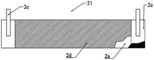
- FIG. 6 is an expanded view of the negative pole piece of the multi-pole lug in Embodiment 2;
- Fig. 7 is an exploded view of the negative pole piece of the bipolar ear in embodiment 3;
- Multi-electrode positive pole piece 1a, current collector aluminum foil; 1b, positive electrode; 1c, positive electrode lead; 1d, positive electrode material coating area; 1e, aluminum foil blank area; 2. Multi-electrode negative electrode Sheet; 2a, current collector copper foil; 2b, negative electrode tab; 2c, negative electrode lead; 2d, negative electrode material coating area; 2e, copper foil blank area; 21, bipolar lug negative pole piece; 3. isolation film.
- the winding core includes a positive pole piece, a negative pole piece and a diaphragm.
- the pole piece is provided with tabs and leads, and includes the following three parallel schemes:
- the positive pole piece is provided with tabs and leads at the same time, and the negative pole piece is provided with tabs;
- the negative pole piece is provided with a tab and a lead at the same time, and the positive pole piece is provided with a tab;
- both the positive pole piece and the negative pole piece are provided with tabs and leads at the same time.
- the number of leads determines the positional relationship between the leads and the tabs.
- the integrally connected tabs are obtained by punching the fluid collector foil.
- the number of tabs is not particularly limited. Usually the number is several. The more the tabs are set, the more Conducive to the effect of reducing impedance.
- the number of leads is one, and the lead is located on one side of the overlapping tabs, that is, the overlapping tabs are set between the lead and the central hole of the core, or the lead is set between the overlapping tabs and the central hole of the core ,
- the non-lead is located between the overlapping tabs; in the above two solutions, it is further preferred that the lead is set between the stacked tabs and the central hole of the core.
- the number of leads is two, and the overlapping tabs are sandwiched between the two leads.
- the lead wire has a better protective effect on the tabs.
- the commonly used positive electrode current collector is aluminum foil.
- the surface of the aluminum foil is coated with positive electrode material.
- the area where the positive electrode material is coated is the electrode material coating area, and the area where the positive electrode material is not coated is the blank area;
- the commonly used negative electrode current collector is Copper foil, the surface of the copper foil is coated with negative electrode material, the area where the negative electrode material is coated is the electrode material coating area, and the area where the negative electrode material is not coated is the blank area.
- the lead is attached to the blank area of the corresponding electrode pole piece.
- the above-mentioned attachment structure is made by welding, such as ultrasonic welding.
- the multi-pole cylindrical battery winding core of Example 1 includes the multi-pole positive pole piece 1, the multi-pole negative pole piece 2, and the separator 3 that are wound on top of each other;
- the multi-pole tab positive pole piece 1 includes a strip-shaped current collector aluminum foil 1a, a plurality of positive tabs 1b, and a positive electrode lead 1c.
- the surface area is the positive electrode material coating area 1d, and the aluminum foil surface area that is not coated with the positive electrode material is the aluminum foil blank area 1e;
- the multi-electrode negative pole piece 2 includes a strip-shaped current collector copper foil 2a, a plurality of negative electrode tabs 2b, and a negative electrode lead 2c. Both sides of the copper foil 2a are coated with negative electrode material and coated with negative electrode material.
- the surface area of the copper foil is the negative electrode material coating area 2d, and the copper foil surface area that is not coated with the negative electrode material is the copper foil blank area 2e;
- a plurality of stacked positive tabs 1b in the winding core are sandwiched between two positive leads 1c, and a plurality of stacked negative tabs 2b are sandwiched between two negative leads 2c, that is, when the tabs are expanded In the figure, multiple tabs on the same pole piece are located between two leads.
- the thickness of the lead is greater than the thickness of the tab.
- Example 2 is based on Example 1. The difference is that the multi-pole cylindrical battery winding core of Example 2 includes multi-pole positive pole pieces 1, separation membrane 2, and multi-pole lugs that are wound on top of each other.
- Negative pole piece 3 wherein a positive electrode lead 1c is provided on the current collector aluminum foil 1a, and the positive electrode lead 1c is located at one end of the inner circle of the current collector aluminum foil 1a, that is, the positive electrode lead 1c is located on the inner side (inside, Take the inner and outer layers of the core as a reference); the current collector copper foil 2a is provided with a negative lead 1c, and the negative lead 1c is located at one end of the inner ring of the current collector copper foil 1a, that is, the negative leads 1c are located in multiple The inner side of the stacked negative pole tabs 2b.
- the positive lead 1c is located inside the multiple positive tabs 1b, and the negative lead 1c is located outside the multiple stacked negative tabs 2b; or the positive lead 1c is located outside the multiple positive tabs 1b, and the negative lead 1c It is located on the inner side of the multiple stacked negative tabs 2b; or the positive lead 1c is located on the outside of the multiple positive tabs 1b, and the negative lead 1c is located on the outside of the multiple stacked negative tabs 2b.
- the protective effect of the lead on the tab depends on the bending direction of the tab during production.
- the multi-pole cylindrical battery winding core of Example 3 includes a multi-pole positive pole piece 1 and a double-pole negative pole piece 21 that are wound on top of each other.
- the structure of the multi-pole positive pole piece 1 is the same In Embodiment 1, only two negative electrode leads 2c are provided on the current collector copper foil 2a of the bipolar lug negative pole piece 21, and no integrally punched negative electrode lug is provided.
- the positive pole piece and the negative pole piece of the multi-pole cylindrical battery winding core are any combination of the positive pole piece and the negative pole piece in the embodiments 1-3 and its alternatives, which can achieve the basic lead protection technology. Effect.
Abstract
本申请公开了一种多极耳圆柱电池卷芯,包括相叠卷绕的极片和隔膜,极片上设置有极耳和引线,极耳与极片一体连接,引线与极片固定连接;同一极片的极耳和引线相叠并位于卷芯中心孔一侧;同一极片上引线位于相叠的极耳一侧,或者同一极片上相叠的极耳夹设于两根引线之间。该多极耳圆柱电池卷芯的同一极片上引线与极耳相叠,并且引线位于相叠极耳的一侧,或者相叠极耳位于两根引线之间,引线起到保护极耳的作用,在采用电阻焊、超声焊等方式连接极耳和壳体或者盖板时,降低极耳破损几率,提高电池的工艺可制造性;极耳数量以及极耳连接结构有助于降低电池阻抗,提高电池输出功率。本申请还公开了一种具有多极耳圆柱电池卷芯的锂离子电池。
Description
本实用新型涉及锂离子电池生产设备技术领域,具体涉及一种多极耳圆柱电池卷芯及锂离子电池。
圆柱型锂离子电池具有能量密度大,循环性能好等优点,被广泛于手机、平板电脑、可穿戴设备、移动电源、电动工具、动力、储能等领域。随着近年汽车电动化进度加速,圆柱电池作为汽车能源成为替代汽油的备选能源,但与电子产品电源不同的是,汽车电源要求更高的能量密度,更高的功率输出以及更高的可靠性。
圆柱形电池卷芯的基本结构包括相叠并卷绕的正极极片、负极极片和隔膜,正极极片上设置有正极极耳、负极极片上设置有负极极耳,正极极耳突出设置于卷芯的一端,负极极耳突出设置于卷芯的另一端。传统的圆柱形电池卷芯在正负极通常只有1-2个极耳,例如CN202721219U中所述的双极耳式锂离子电池卷芯卷绕体,包括极片带、第一极耳、第二极耳,其中第一极耳和第二极耳焊接在极片带上。上述卷芯卷绕体装配制得的电池阻抗高,热分布不合理,无法满足日益增加的车载电池要求。
改进的技术方案如CN205028971U中的圆柱形软包装锂离子电池,其中的正极极片上切割有多个铝箔极耳,负极极片上切割有多个铜箔极耳,根据卷芯的直径计算,使得极片卷绕过程中极耳内层与外层重叠。但在实际生产中,由于集流体本身材质较薄,重叠的极耳强度低,后续工艺组装过程中例如极耳与壳体或者盖板连接时破裂的现象,也无法满足产品实际使用性能需求。
实用新型内容
本实用新型的目的在于克服现有技术中存在的缺陷,提供一种多极耳圆柱电池卷芯,包含该卷芯的的锂离子电池阻抗低,电池输出功率高。
实现上述技术效果,本实用新型的技术方案为:一种多极耳圆柱电池卷芯,包括相叠卷绕的极片和隔膜,所述极片上设置有一体连接的极耳,至少一个所述极片上固定连接有引线;同一极片的所述极耳和引线相叠并位于卷芯中心孔一侧;同一极片上所述引线位于相叠的所述极耳一侧,或者同一极片上相叠的所述极耳夹设于两根引线之间。
优选的技术方案为,同一极片上所述引线位于相叠的所述极耳一侧,且所述引线设置于相叠的所述极耳与所述卷芯中心孔之间。
优选的技术方案为,所述极片包括正极极片和负极极片;所述正极极片上设置有正极极耳和正极引线,所述负极极片上设置有负极极耳和负极引线。
优选的技术方案为,所述极片包括集流体,所述集流体的表面包括电极材料涂覆区和空白区,所述引线与所述集流体的空白区连接。
优选的技术方案为,引线的厚度大于所述极耳的厚度。
本实用新型的目的之二在于提供一种锂离子电池,包括上述的多极耳圆柱电池卷芯。
本实用新型的优点和有益效果在于:
该多极耳圆柱电池卷芯的同一极片上引线与极耳相叠,并且引线位于相叠极耳的一侧,或者相叠极耳位于两根引线之间,引线能够起到保护极耳的作用,在采用电阻焊、超声焊等方式将极耳连接在壳体或者盖板上时,降低极耳破损的几率,有效提高电池的工艺可制造性;
极耳数量的增加以及极耳连接结构的变化能够有效降低电池阻抗,提高电池输出功率。
图1是实施例1多极耳圆柱电池卷芯的卷绕结构示意图;
图2是实施例1的立体结构示意图;
图3是实施例1中多极耳正极极片的展开图;
图4是实施例1中多极耳负极极片的展开图;
图5是实施例2中多极耳正极极片的展开图;
图6是实施例2中多极耳负极极片的展开图;
图7是实施例3中双极耳负极极片的展开图;
图中:1、多极耳正极极片;1a、集流体铝箔;1b、正极极耳;1c、正极引线;1d、正极材料涂覆区;1e、铝箔空白区;2、多极耳负极极片;2a、集流体铜箔;2b、负极极耳;2c、负极引线;2d、负极材料涂覆区;2e、铜箔空白区;21、双极耳负极极片;3、隔离膜。
下面结合附图和实施例,对本实用新型的具体实施方式作进一步描述。以下实施例仅用于更加清楚地说明本实用新型的技术方案,而不能以此来限制本实用新型的保护范围。
卷芯中包括正极极片、负极极片和隔膜,极片上设置有极耳和引线,并且包括以下三种并列方案:
第一、正极极片上同时设置极耳和引线,负极极片上设置有极耳;
第二、负极极片上同时设置极耳和引线,正极极片上设置有极耳;
第三、正极极片和负极极片上均同时设置极耳和引线。
引线的数量决定了引线和极耳的位置关系,一体连接的极耳通过冲切集流体箔材得到,极耳的数量没有特别的限制,通常数量为若干根,极耳趋多设置,越有利于降低阻抗的效果。
引线的数量为一根,引线位于相叠极耳的一侧,即相叠的极耳设置于引线和卷芯中心孔之间,或者引线设置于相叠的极耳与卷芯中心 孔之间,而非引线位于相叠的极耳之间;上述两方案中进一步优选的,引线设置于相叠的极耳与卷芯中心孔之间。
引线的数量为两根,相叠的极耳夹设与两根引线之间。该层叠结构中引线对于极耳的保护作用更优。
常用的正极极片集流体为铝箔,铝箔的表面涂覆正极材料,涂覆正极材料的区域为电极材料涂覆区,未涂覆正极材料的区域为空白区;常用的负极极片集流体为铜箔,铜箔的表面涂覆负极材料,涂覆负极材料的区域为电极材料涂覆区,未涂覆负极材料的区域为空白区。引线贴附与相应电极极片的空白区。通常的,上述贴附结构通过焊接制成,例如超声焊等。
实施例1
如图1-4所示,实施例1多极耳圆柱电池卷芯,包括相叠卷绕的多极耳正极极片1、多极耳负极极片2、隔离膜3;
如图3所示,多极耳正极极片1包含带状的集流体铝箔1a、多个正极极耳1b、正极引线1c,铝箔1a的双面涂覆有正极材料,涂覆正极材料的铝箔表面区域为正极材料涂覆区1d,未涂覆正极材料的铝箔表面区域为铝箔空白区1e;
如图4所示,多极耳负极极片2包含带状的集流体铜箔2a、多个负极极耳2b、负极引线2c,铜箔2a的双面涂布有负极材料,涂覆负极材料的铜箔表面区域为负极材料涂覆区2d,未涂覆负极材料的铜箔表面区域为铜箔空白区2e;
卷芯中相叠的多个正极极耳1b夹设于两根正极引线1c之间,且相叠的多个负极极耳2b夹设于两根负极引线2c之间,即在极片的展开图中,同一极片上的多个极耳位于两根引线之间。
引线的厚度大于极耳的厚度。
实施例2
如图5-6所示,实施例2基于实施例1,区别在于,实施例2多 极耳圆柱电池卷芯包括相叠卷绕的多极耳正极极片1、隔离膜2、多极耳负极极片3,其中,集流体铝箔1a上设置有一根正极引线1c,正极引线1c位于集流体铝箔1a卷芯内圈的一端,即正极引线1c位于多个正极极耳1b的内侧(内、外以卷芯的内层和外层作为参照);集流体铜箔2a上设置有一根负极引线1c,负极引线1c位于集流体铜箔1a卷芯内圈的一端,即负极引线1c位于多个相叠的负极极耳2b的内侧。
作为替代方案,正极引线1c位于多个正极极耳1b的内侧,负极引线1c位于多个相叠的负极极耳2b的外侧;或者正极引线1c位于多个正极极耳1b的外侧,负极引线1c位于多个相叠的负极极耳2b的内侧;或者正极引线1c位于多个正极极耳1b的外侧,负极引线1c位于多个相叠的负极极耳2b的外侧。引线对于极耳的保护作用取决于生产中极耳的弯折方向。
实施例3
如图7所示,实施例3的多极耳圆柱电池卷芯,包括相叠卷绕的多极耳正极极片1和双极耳负极极片21,多极耳正极极片1的结构同实施例1,双极耳负极极片21的集流体铜箔2a上仅设置有两个负极引线2c,未设置一体冲切的负极极耳。
作为替代方案,集流体铜箔2a上仅设置有若干个负极极耳2b,未设置负极引线2c;或者集流体铝箔1a上仅设置有若干个正极极耳1b,多极耳负极极片2的结构同实施例1;或者集流体铝箔1a上仅设置有若干个正极极耳1b,多极耳负极极片2的结构同实施例1。
多极耳圆柱电池卷芯的正极极片和负极极片为实施例1-3及其替换方案中任意一种正极极片和负极极片的组合,均能达到基本的引线保护极耳的技术效果。
以上所述仅是本实用新型的优选实施方式,应当指出,对于本技术领域的普通技术人员来说,在不脱离本实用新型技术原理的前提 下,还可以做出若干改进和润饰,这些改进和润饰也应视为本实用新型的保护范围。
Claims (6)
- 一种多极耳圆柱电池卷芯,包括相叠卷绕的极片和隔膜,所述极片上设置有一体连接的极耳,至少一个所述极片上固定连接有引线;同一极片的所述极耳和引线相叠并位于卷芯中心孔一侧;其特征在于,同一极片上所述引线位于相叠的所述极耳一侧,或者同一极片上相叠的所述极耳夹设于两根引线之间。
- 根据权利要求1所述的多极耳圆柱电池卷芯,其特征在于,同一极片上所述引线位于相叠的所述极耳一侧,且所述引线设置于相叠的所述极耳与所述卷芯中心孔之间。
- 根据权利要求1所述的多极耳圆柱电池卷芯,其特征在于,所述极片包括正极极片和负极极片;所述正极极片上设置有正极极耳和正极引线,所述负极极片上设置有负极极耳和负极引线。
- 根据权利要求1所述的多极耳圆柱电池卷芯,其特征在于,所述极片包括集流体,所述集流体的表面包括电极材料涂覆区和空白区,所述引线与所述集流体的空白区连接。
- 根据权利要求1所述的多极耳圆柱电池卷芯,其特征在于,引线的厚度大于所述极耳的厚度。
- 一种锂离子电池,其特征在于,包括权利要求1至5中任意一项所述的多极耳圆柱电池卷芯。
Priority Applications (2)
| Application Number | Priority Date | Filing Date | Title |
|---|---|---|---|
| DE212020000679.2U DE212020000679U1 (de) | 2020-05-18 | 2020-11-20 | Zylindrischer Batterierollkern mit mehreren Laschen und Lithium-lonen-Batterie |
| US17/545,834 US20220102817A1 (en) | 2020-05-18 | 2021-12-08 | Multi-tab cylindrical battery roll core and lithium ion battery |
Applications Claiming Priority (2)
| Application Number | Priority Date | Filing Date | Title |
|---|---|---|---|
| CN202020825061.2 | 2020-05-18 | ||
| CN202020825061.2U CN211907618U (zh) | 2020-05-18 | 2020-05-18 | 一种多极耳圆柱电池卷芯及锂离子电池 |
Related Child Applications (1)
| Application Number | Title | Priority Date | Filing Date |
|---|---|---|---|
| US17/545,834 Continuation-In-Part US20220102817A1 (en) | 2020-05-18 | 2021-12-08 | Multi-tab cylindrical battery roll core and lithium ion battery |
Publications (1)
| Publication Number | Publication Date |
|---|---|
| WO2021232720A1 true WO2021232720A1 (zh) | 2021-11-25 |
Family
ID=73270651
Family Applications (1)
| Application Number | Title | Priority Date | Filing Date |
|---|---|---|---|
| PCT/CN2020/130545 WO2021232720A1 (zh) | 2020-05-18 | 2020-11-20 | 一种多极耳圆柱电池卷芯及锂离子电池 |
Country Status (4)
| Country | Link |
|---|---|
| US (1) | US20220102817A1 (zh) |
| CN (1) | CN211907618U (zh) |
| DE (1) | DE212020000679U1 (zh) |
| WO (1) | WO2021232720A1 (zh) |
Families Citing this family (3)
| Publication number | Priority date | Publication date | Assignee | Title |
|---|---|---|---|---|
| CN211907618U (zh) * | 2020-05-18 | 2020-11-10 | 联动天翼新能源有限公司 | 一种多极耳圆柱电池卷芯及锂离子电池 |
| CN217387457U (zh) * | 2021-12-21 | 2022-09-06 | 比亚迪股份有限公司 | 电池单元、电池模组和车辆 |
| CN216563209U (zh) * | 2021-12-30 | 2022-05-17 | 珠海冠宇电池股份有限公司 | 极片、卷芯和电池 |
Citations (6)
| Publication number | Priority date | Publication date | Assignee | Title |
|---|---|---|---|---|
| CN203119048U (zh) * | 2012-12-27 | 2013-08-07 | 东莞市安德丰电池有限公司 | 一种双极耳电池卷芯及其锂离子电池 |
| JP2013187077A (ja) * | 2012-03-08 | 2013-09-19 | Panasonic Corp | 捲回型およびスタック型電極電池 |
| CN106129319A (zh) * | 2015-05-06 | 2016-11-16 | 三星电子株式会社 | 用于二次电池的单元结构体和具有单元结构体的二次电池 |
| CN106257710A (zh) * | 2015-06-17 | 2016-12-28 | 深圳市沃特玛电池有限公司 | 一种多极耳变尺寸的高倍率锂离子电池 |
| CN108963175A (zh) * | 2018-06-23 | 2018-12-07 | 深圳市创景新能源科技有限公司 | 电池的极片结构、电池卷芯和电池卷芯的制作方法 |
| CN211907618U (zh) * | 2020-05-18 | 2020-11-10 | 联动天翼新能源有限公司 | 一种多极耳圆柱电池卷芯及锂离子电池 |
Family Cites Families (2)
| Publication number | Priority date | Publication date | Assignee | Title |
|---|---|---|---|---|
| CN202721219U (zh) | 2012-05-23 | 2013-02-06 | 深圳市迪凯特电池科技有限公司 | 双极耳式锂离子电池卷芯卷绕体 |
| CN205028971U (zh) | 2015-10-15 | 2016-02-10 | 青岛领军节能与新材料研究院 | 一种圆柱型软包装锂离子电池 |
-
2020
- 2020-05-18 CN CN202020825061.2U patent/CN211907618U/zh active Active
- 2020-11-20 DE DE212020000679.2U patent/DE212020000679U1/de active Active
- 2020-11-20 WO PCT/CN2020/130545 patent/WO2021232720A1/zh active Application Filing
-
2021
- 2021-12-08 US US17/545,834 patent/US20220102817A1/en active Pending
Patent Citations (6)
| Publication number | Priority date | Publication date | Assignee | Title |
|---|---|---|---|---|
| JP2013187077A (ja) * | 2012-03-08 | 2013-09-19 | Panasonic Corp | 捲回型およびスタック型電極電池 |
| CN203119048U (zh) * | 2012-12-27 | 2013-08-07 | 东莞市安德丰电池有限公司 | 一种双极耳电池卷芯及其锂离子电池 |
| CN106129319A (zh) * | 2015-05-06 | 2016-11-16 | 三星电子株式会社 | 用于二次电池的单元结构体和具有单元结构体的二次电池 |
| CN106257710A (zh) * | 2015-06-17 | 2016-12-28 | 深圳市沃特玛电池有限公司 | 一种多极耳变尺寸的高倍率锂离子电池 |
| CN108963175A (zh) * | 2018-06-23 | 2018-12-07 | 深圳市创景新能源科技有限公司 | 电池的极片结构、电池卷芯和电池卷芯的制作方法 |
| CN211907618U (zh) * | 2020-05-18 | 2020-11-10 | 联动天翼新能源有限公司 | 一种多极耳圆柱电池卷芯及锂离子电池 |
Also Published As
| Publication number | Publication date |
|---|---|
| DE212020000679U1 (de) | 2022-05-20 |
| US20220102817A1 (en) | 2022-03-31 |
| CN211907618U (zh) | 2020-11-10 |
Similar Documents
| Publication | Publication Date | Title |
|---|---|---|
| WO2021232720A1 (zh) | 一种多极耳圆柱电池卷芯及锂离子电池 | |
| CN209981369U (zh) | 一种圆柱型电池 | |
| CN112864350A (zh) | 电芯及电池 | |
| CN216488280U (zh) | 一种具有新型电池盖板连接结构的电芯 | |
| WO2007079617A1 (en) | A button-type battery | |
| CN212571274U (zh) | 锂离子电池及电子设备 | |
| WO2022082437A1 (zh) | 电池和具有所述电池的电子装置 | |
| CN207530032U (zh) | 一种高密封防漏液的锂离子电池极耳 | |
| CN212380471U (zh) | 硬壳纽扣电池 | |
| CN212230543U (zh) | 一种叠片式曲面电池 | |
| CN211578871U (zh) | 一种防电芯短路的极耳及电芯 | |
| WO2021195852A1 (zh) | 电池组件、应用所述电池组件的电池及电子装置 | |
| CN112968207A (zh) | 一种复合式电池 | |
| WO2022188893A1 (zh) | 一种电芯 | |
| CN207474594U (zh) | 一种锂离子圆柱电池 | |
| CN113381132B (zh) | 一种多极耳电芯和电池 | |
| CN214754076U (zh) | 电芯结构以及锂离子电池 | |
| CN215644569U (zh) | 一种用于卷绕式多极耳电芯的集流体结构 | |
| CN213340472U (zh) | 卷芯、电池以及电子产品 | |
| CN113851793A (zh) | 一种多极耳电芯、电池及电池制作方法 | |
| WO2021012685A1 (zh) | 层叠极耳、极片、电芯和电池 | |
| WO2021195924A1 (zh) | 电芯结构及电池 | |
| CN110419133B (zh) | 电极组件及其制造方法 | |
| CN112968219A (zh) | 一种电芯、电池模组、电池包及电池的制作方法 | |
| CN105655533A (zh) | 一种锂离子电池﹑制作方法及其极耳处理方法 |
Legal Events
| Date | Code | Title | Description |
|---|---|---|---|
| 121 | Ep: the epo has been informed by wipo that ep was designated in this application |
Ref document number: 20936136 Country of ref document: EP Kind code of ref document: A1 |
|
| 122 | Ep: pct application non-entry in european phase |
Ref document number: 20936136 Country of ref document: EP Kind code of ref document: A1 |