WO2021229752A1 - 画像記憶装置、画像記憶方法、及びプログラム - Google Patents
画像記憶装置、画像記憶方法、及びプログラム Download PDFInfo
- Publication number
- WO2021229752A1 WO2021229752A1 PCT/JP2020/019257 JP2020019257W WO2021229752A1 WO 2021229752 A1 WO2021229752 A1 WO 2021229752A1 JP 2020019257 W JP2020019257 W JP 2020019257W WO 2021229752 A1 WO2021229752 A1 WO 2021229752A1
- Authority
- WO
- WIPO (PCT)
- Prior art keywords
- image
- display
- display area
- real
- storage device
- Prior art date
- Legal status (The legal status is an assumption and is not a legal conclusion. Google has not performed a legal analysis and makes no representation as to the accuracy of the status listed.)
- Ceased
Links
Images


Classifications
-
- G—PHYSICS
- G06—COMPUTING OR CALCULATING; COUNTING
- G06F—ELECTRIC DIGITAL DATA PROCESSING
- G06F3/00—Input arrangements for transferring data to be processed into a form capable of being handled by the computer; Output arrangements for transferring data from processing unit to output unit, e.g. interface arrangements
- G06F3/14—Digital output to display device ; Cooperation and interconnection of the display device with other functional units
-
- G—PHYSICS
- G06—COMPUTING OR CALCULATING; COUNTING
- G06T—IMAGE DATA PROCESSING OR GENERATION, IN GENERAL
- G06T5/00—Image enhancement or restoration
- G06T5/50—Image enhancement or restoration using two or more images, e.g. averaging or subtraction
-
- G—PHYSICS
- G06—COMPUTING OR CALCULATING; COUNTING
- G06T—IMAGE DATA PROCESSING OR GENERATION, IN GENERAL
- G06T7/00—Image analysis
- G06T7/10—Segmentation; Edge detection
- G06T7/13—Edge detection
-
- G—PHYSICS
- G06—COMPUTING OR CALCULATING; COUNTING
- G06T—IMAGE DATA PROCESSING OR GENERATION, IN GENERAL
- G06T7/00—Image analysis
- G06T7/70—Determining position or orientation of objects or cameras
-
- G—PHYSICS
- G09—EDUCATION; CRYPTOGRAPHY; DISPLAY; ADVERTISING; SEALS
- G09G—ARRANGEMENTS OR CIRCUITS FOR CONTROL OF INDICATING DEVICES USING STATIC MEANS TO PRESENT VARIABLE INFORMATION
- G09G5/00—Control arrangements or circuits for visual indicators common to cathode-ray tube indicators and other visual indicators
- G09G5/36—Control arrangements or circuits for visual indicators common to cathode-ray tube indicators and other visual indicators characterised by the display of a graphic pattern, e.g. using an all-points-addressable [APA] memory
- G09G5/38—Control arrangements or circuits for visual indicators common to cathode-ray tube indicators and other visual indicators characterised by the display of a graphic pattern, e.g. using an all-points-addressable [APA] memory with means for controlling the display position
-
- H—ELECTRICITY
- H04—ELECTRIC COMMUNICATION TECHNIQUE
- H04N—PICTORIAL COMMUNICATION, e.g. TELEVISION
- H04N23/00—Cameras or camera modules comprising electronic image sensors; Control thereof
- H04N23/60—Control of cameras or camera modules
- H04N23/63—Control of cameras or camera modules by using electronic viewfinders
- H04N23/633—Control of cameras or camera modules by using electronic viewfinders for displaying additional information relating to control or operation of the camera
-
- H—ELECTRICITY
- H04—ELECTRIC COMMUNICATION TECHNIQUE
- H04N—PICTORIAL COMMUNICATION, e.g. TELEVISION
- H04N23/00—Cameras or camera modules comprising electronic image sensors; Control thereof
- H04N23/60—Control of cameras or camera modules
- H04N23/698—Control of cameras or camera modules for achieving an enlarged field of view, e.g. panoramic image capture
-
- H—ELECTRICITY
- H04—ELECTRIC COMMUNICATION TECHNIQUE
- H04N—PICTORIAL COMMUNICATION, e.g. TELEVISION
- H04N23/00—Cameras or camera modules comprising electronic image sensors; Control thereof
- H04N23/95—Computational photography systems, e.g. light-field imaging systems
- H04N23/951—Computational photography systems, e.g. light-field imaging systems by using two or more images to influence resolution, frame rate or aspect ratio
-
- G—PHYSICS
- G06—COMPUTING OR CALCULATING; COUNTING
- G06T—IMAGE DATA PROCESSING OR GENERATION, IN GENERAL
- G06T2207/00—Indexing scheme for image analysis or image enhancement
- G06T2207/20—Special algorithmic details
- G06T2207/20092—Interactive image processing based on input by user
- G06T2207/20104—Interactive definition of region of interest [ROI]
-
- G—PHYSICS
- G06—COMPUTING OR CALCULATING; COUNTING
- G06T—IMAGE DATA PROCESSING OR GENERATION, IN GENERAL
- G06T2207/00—Indexing scheme for image analysis or image enhancement
- G06T2207/20—Special algorithmic details
- G06T2207/20212—Image combination
- G06T2207/20221—Image fusion; Image merging
-
- G—PHYSICS
- G06—COMPUTING OR CALCULATING; COUNTING
- G06T—IMAGE DATA PROCESSING OR GENERATION, IN GENERAL
- G06T2207/00—Indexing scheme for image analysis or image enhancement
- G06T2207/30—Subject of image; Context of image processing
- G06T2207/30244—Camera pose
-
- G—PHYSICS
- G09—EDUCATION; CRYPTOGRAPHY; DISPLAY; ADVERTISING; SEALS
- G09G—ARRANGEMENTS OR CIRCUITS FOR CONTROL OF INDICATING DEVICES USING STATIC MEANS TO PRESENT VARIABLE INFORMATION
- G09G2340/00—Aspects of display data processing
- G09G2340/04—Changes in size, position or resolution of an image
- G09G2340/0464—Positioning
-
- G—PHYSICS
- G09—EDUCATION; CRYPTOGRAPHY; DISPLAY; ADVERTISING; SEALS
- G09G—ARRANGEMENTS OR CIRCUITS FOR CONTROL OF INDICATING DEVICES USING STATIC MEANS TO PRESENT VARIABLE INFORMATION
- G09G2354/00—Aspects of interface with display user
Definitions
- the present invention relates to an image storage device, an image storage method, and a program.
- Patent Document 1 describes that a server acquires information indicating an arrangement of goods on a shelf from a retailer and analyzes whether or not this arrangement is in a predetermined position.
- Patent Document 2 describes that a plurality of divided images are generated by appropriately dividing and imaging the product shelves, and these divided images are combined to generate an image of a panoramic view of the product shelves. This panoramic image is displayed on the customer's terminal when selling the product to the customer on the Internet.
- One of the objects of the present invention is to make it easy to photograph the shelves on which the articles are placed in a plurality of times without any gaps.
- an image acquisition means for acquiring a first image obtained by capturing a part of an article shelf on which an article is placed, and an image acquisition means. While displaying at least the end of the first image in the first display area which is a part of the display means, the real-time image currently repeatedly generated by the image pickup means is adjacent to the first display area of the display means.
- the storage processing means to perform An image storage device comprising the above is provided.
- the computer Obtain the first image of a part of the article shelf on which the article is placed, While displaying at least the end of the first image in the first display area which is a part of the display means, the real-time image currently repeatedly generated by the image pickup means is adjacent to the first display area of the display means. Display in the second display area Predetermined processing for storing the real-time image or an image generated thereafter as a second image in the storage means when the continuity between the end portion of the first image and the real-time image in the display means meets the criteria.
- An image storage device is provided.
- the computer An image acquisition function that acquires the first image of a part of the article shelf on which the article is placed, and While displaying at least the end of the first image in the first display area which is a part of the display means, the real-time image currently repeatedly generated by the image pickup means is adjacent to the first display area of the display means.
- the display processing function to be displayed in the second display area and Predetermined processing for storing the real-time image or an image generated thereafter as a second image in the storage means when the continuity between the end of the first image and the real-time image in the display means meets the criteria.
- the memory processing function to perform Is provided.
- FIG. 1 is a diagram for explaining a usage environment of the image pickup apparatus 10 according to the present embodiment.
- the image pickup device 10 is an example of an image storage device, and photographs an article shelf (for example, a product shelf).
- the image generated by the image pickup device 10 is transmitted to the external device 20.
- the external device 20 identifies the position of an article (for example, a product) on the article shelf by processing the image acquired from the image pickup device 10.
- the person who uses the external device 20 confirms whether or not the position of the article on the article shelf is a desired position by using the processing result of the external device 20.
- the external device 20 identifies the position of the article by performing image processing, and determines whether or not the specified position is in a predetermined position.
- the image pickup device 10 is a portable device.
- the image pickup device 10 may be a communication device having an image pickup function, such as a so-called smartphone.
- the user of the image pickup apparatus 10 divides the article shelf into a plurality of areas (for example, the first shelf area A 1 and the second shelf area A 2 ), and generates an image for each area.
- the user of the imaging device 10 after generating the first image by photographing the first shelf area A 1, when generating the second image by photographing the second shelf area A 2, the first Make sure that the edges of the image and the edges of the second image overlap (that is, the images are in the same area). By doing so, the user of the image pickup apparatus 10 can take an image of the article shelf without a gap.
- the image pickup device 10 when the image pickup device 10 generates the second image, the image pickup device 10 guides the end portion of the first image and the end portion of the second image so as to overlap each other. Therefore, the user of the image pickup apparatus 10 can easily overlap the end portion of the first image and the end portion of the second image.
- FIG. 2 is a diagram showing an example of the functional configuration of the image pickup apparatus 10.
- the image pickup apparatus 10 includes an image pickup unit 110, an image acquisition unit 120, a display processing unit 130, a display 140 (an example of a display unit), a storage processing unit 150, and an image storage unit 160.
- the image pickup unit 110 has an image pickup sensor and repeatedly generates an image.
- the image acquisition unit 120 acquires the image generated by the image pickup unit 110.
- the storage processing unit 150 stores in the image storage unit 160 an image that satisfies the conditions among the images generated by the image pickup unit 110.
- the display processing unit 130 displays the image acquired by the image acquisition unit 120 on the display 140.
- the display processing unit 130 displays at least an end portion of the first image in the first display area which is a part of the display 140.
- the latest image (hereinafter referred to as a real-time image) generated by the image pickup unit 110 is repeatedly displayed in the second display area adjacent to the first display area in the display 140.
- the storage processing unit 150 stores the real-time image or the image generated thereafter as the second image in the image storage unit 160 when the continuity of the edge of the first image and the real-time image on the display 140 meets the criteria. Perform a process for causing the image (hereinafter referred to as a predetermined process).
- the first example of the predetermined process is to enable the image pickup button included in the image pickup device 10.
- a predetermined process is to enable a signal generated by pressing the image pickup button.
- the predetermined process is to display the image pickup button on the touch panel.
- the second image stored by pressing the image pickup button may be a real-time image displayed on the display 140 when the continuity meets the criteria, or at the timing when the image pickup button is pressed. It may be a real-time image.
- the second example of the predetermined process is to store the real-time image displayed on the display 140 when the continuity meets the standard in the image storage unit 160 as the second image.
- the image pickup device 10 further includes a transmission unit 170.
- the transmission unit 170 transmits the image stored in the image storage unit 160 to the external device 20.
- the timing at which the transmission unit 170 transmits an image to the external device 20 may be, for example, each time the image is stored in the image storage unit 160, or may be performed in a batch format.
- the image pickup device 10 does not have to have the image storage unit 160.
- the storage processing unit 150 outputs this image to the transmission unit 170 instead of storing the image in the image storage unit 160.
- the transmission unit 170 transmits the image acquired from the storage processing unit 150 to the external device 20 and stores it. Then, the display processing unit 130 stores the image output by the storage processing unit 150 to the transmission unit 170 immediately before as the first image.
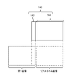
- FIG. 3 is a diagram showing a first example of the first display area 142 and the second display area 144 in the display 140.
- the first shelf area A 1 included in the first image and the second shelf area A 2 included in the second image are adjacent to each other in the horizontal direction.
- the first display area 142 is located at the lateral end of the display 140.
- the second display area 144 is the remaining area of the display 140.
- the lateral end portion of the first image is displayed in the first display area 142, and the entire real-time image is displayed in the second display area 144.
- the storage processing unit 150 is located at the end of the image displayed in the first display area 142 on the second display area 144 side and on the first display area 142 side of the image displayed in the second display area 144.
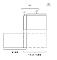
- FIG. 4 is a diagram showing a second example of the first display area 142 and the second display area 144 in the display 140.
- the second shelf area A 2 of the first stage region A 1 and the second image first image includes contains are adjacent in the transverse direction.
- the first display area 142 is displayed in a state where the lateral end portion of the first image and the end portion of the real-time image are overlapped, and the second display area 144 is displayed with the remaining portion of the real-time image.
- the user of the image pickup apparatus 10 adjusts the image pickup direction of the image pickup apparatus 10 so that the lateral end portion of the first image and the end portion of the real-time image coincide with each other in the first display area 142.
- the storage processing unit 150 performs the above-mentioned predetermined processing when the difference between the end portion of the first image and the end portion of the real-time image in the first display area 142 becomes equal to or less than the reference.
- the storage processing unit 150 compares the pixel value at the end of the first image with the pixel value at the end of the real-time image, and when the difference between them becomes equal to or less than the reference, the predetermined processing described above is performed. I do. Further, the storage processing unit 150 detects the type and position of the article contained in the end portion of the first image, and also detects the type and position of the article contained in the end portion of the second image, and the difference between them is a reference. When the following occurs, the above-mentioned predetermined processing is performed. In the latter case, the storage processing unit 150 requires that all types of articles match, and when the result of statistical processing (for example, average value or total value) of the difference in position of each object becomes less than the standard. In addition, the above-mentioned predetermined processing may be performed.
- the article is at the end of the image as compared with the example shown in FIG. It is possible to suppress the appearance of only a part. For this reason, it is highly possible that at least one image contains the whole image of any of the articles placed on the article shelves.
- FIG. 5 is a diagram showing a third example of the first display area 142 and the second display area 144 in the display 140.
- Example shown in the drawing, and except that the second shelf area A 2 of the first stage region A 1 and the second image first image includes contains are adjacent in the vertical direction, as shown in FIG Example The same is true. Therefore, in the example shown in this figure, the first display area 142 is located at the upper end (or lower side) end of the display 140. In the example shown in this figure, the relationship between the first image and the second image may be the same as in FIG.
- FIG. 6 is a diagram showing a hardware configuration example of the image pickup apparatus 10.
- the image pickup apparatus 10 includes a bus 1010, a processor 1020, a memory 1030, a storage device 1040, an input / output interface 1050, and a network interface 1060.
- the bus 1010 is a data transmission path for the processor 1020, the memory 1030, the storage device 1040, the input / output interface 1050, and the network interface 1060 to transmit and receive data to each other.
- the method of connecting the processors 1020 and the like to each other is not limited to the bus connection.
- the processor 1020 is a processor realized by a CPU (Central Processing Unit), a GPU (Graphics Processing Unit), or the like.
- the memory 1030 is a main storage device realized by a RAM (RandomAccessMemory) or the like.
- the storage device 1040 is an auxiliary storage device realized by an HDD (Hard Disk Drive), SSD (Solid State Drive), memory card, ROM (Read Only Memory), or the like.
- the storage device 1040 stores a program module that realizes each function of the image pickup apparatus 10 (for example, an image acquisition unit 120, a display processing unit 130, a storage processing unit 150, and a transmission unit 170).
- the processor 1020 reads each of these program modules into the memory 1030 and executes them, each function corresponding to the program module is realized.
- the storage device 1040 also functions as an image storage unit 160.
- the input / output interface 1050 is an interface for connecting the main part of the image pickup apparatus 10 and various input / output devices (for example, the display 140).
- the network interface 1060 is an interface for connecting the image pickup apparatus 10 to the network.
- This network is, for example, LAN (Local Area Network) or WAN (Wide Area Network).
- the method of connecting the network interface 1060 to the network may be a wireless connection or a wired connection.
- the image pickup device 10 may communicate with the external device 20 via the network interface 1060.
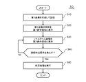
- FIG. 7 is a flowchart showing an example of the processing performed by the image pickup apparatus 10.
- the image pickup unit 110 of the image pickup apparatus 10 generates an image to be the first image.
- the storage processing unit 150 stores this image as a first image in the image storage unit 160 (step S10).
- the display processing unit 130 reads out the first image from the image storage unit 160, and displays the end portion of the first image in the first display area 142 of the display 140 (step S20).
- step S30 the display processing unit 130 displays the real-time image currently generated by the image pickup unit 110 in the second display area 144 of the display 140 (step S30). Then, when the continuity of the image displayed in the first display area 142 and the image displayed in the second display area 144 satisfies the criteria (step S40: Yes), the storage processing unit 150 displays the second image. A predetermined process for storing in the image storage unit 160 is executed (step S50).
- the determination criteria in step S40 are an example described with reference to FIG. 3 and an example described with reference to FIG.
- the display processing unit 130 of the image pickup apparatus 10 displays at least an end portion of the first image obtained by capturing a part of the article shelf in the first display area 142 of the display 140, while displaying the image pickup unit.
- the real-time image currently repeatedly generated by 110 is displayed in the second display area 144 of the display 140.
- the storage processing unit 150 stores the real-time image as a second image in the image storage unit 160 when the continuity of the first display area 142 and the second display area 144 in the display 140 satisfies the standard. Therefore, when the article shelf is photographed in a plurality of times, the article shelf can be photographed without a gap.
- FIG. 8 is a diagram showing an example of the functional configuration of the image pickup apparatus 10 according to the present embodiment.
- the image pickup apparatus 10 according to the present embodiment has the same configuration as the image pickup apparatus 10 according to the first embodiment, except that the image pickup apparatus 10 includes the direction acquisition unit 180.
- the direction acquisition unit 180 acquires the designation of the direction in which the first display area 142 and the second display area 144 are arranged. This designation may be input by the user, for example, via the input device of the image pickup device 10, or may be transmitted by the external device 20 to the image pickup device 10.
- There are four examples of the designated direction as follows.
- the second display area 144 is located on the right side of the first display area 142. (2) The second display area 144 is located on the left side of the first display area 142. (3) The second display area 144 is located above the first display area 142. (4) The second display area 144 is located below the first display area 142.
- the display processing unit 130 performs processing according to the designation acquired by the direction acquisition unit 180.
- the direction acquisition unit 180 acquires the designation of the direction in which the first display area 142 and the second display area 144 are arranged.
- the direction specified here indicates the direction in which the first shelf area A1 and the second shelf area A2 of the article shelves are lined up, that is, the direction in which the article shelves are divided when the article shelves are separately photographed. Therefore, the user of the image pickup apparatus 10 can easily take an image of the article shelf along the dividing direction.
- FIG. 9 is a diagram showing an example of the functional configuration of the image pickup apparatus 10 according to the present embodiment.
- the image pickup apparatus 10 shown in this figure has the same configuration as the image pickup apparatus 10 according to the second embodiment except for the following points.
- the image pickup apparatus 10 does not include the direction acquisition unit 180. Instead, the image pickup device 10 includes a sensor 190.
- the sensor 190 has, for example, at least one of an acceleration sensor and a gyro sensor, and detects at least one of the moving direction and the inclination of the image pickup apparatus 10.
- the display processing unit 130 determines the direction in which the first display area 142 and the second display area 144 are aligned by using the detection value of the sensor 190 after generating the first image.
- Specific examples of the line-up direction are as described in the second embodiment.
- the display processing unit 130 when the acceleration sensor detects acceleration in a certain direction, the display processing unit 130 means that the image pickup apparatus 10 has moved in that direction, so that the second display area 144 is set with respect to the first display area 142. Place in that direction. For example, when the acceleration sensor detects acceleration to the right, the display processing unit 130 arranges the second display area 144 on the right side of the first display area 142. Further, when the acceleration sensor detects downward acceleration, the display processing unit 130 arranges the second display area 144 below the first display area 142.
- the sensor 190 has a gyro sensor.
- the display processing unit 130 detects the rotation of the gyro sensor in a certain direction, the direction of the image pickup apparatus 10 is changed in that direction. Therefore, the second display area 144 is changed to the first display area 142.
- place it in that direction For example, when the gyro sensor detects rotation to the right, the display processing unit 130 arranges the second display area 144 on the right side of the first display area 142. Further, when the gyro sensor detects the downward rotation, the display processing unit 130 arranges the second display area 144 below the first display area 142.
- An image acquisition means for acquiring a first image of a part of an article shelf on which an article is placed, and an image acquisition means. While displaying at least the end of the first image in the first display area which is a part of the display means, the real-time image currently repeatedly generated by the image pickup means is adjacent to the first display area of the display means.
- Display processing means to be displayed in the second display area and Predetermined processing for storing the real-time image or an image generated thereafter as a second image in the storage means when the continuity of the edge of the first image and the real-time image in the display means meets the criteria. And the storage processing means to perform Image storage device. 2.
- the display processing means causes the end of the first image and the end of the real-time image to be overlapped and displayed in the first display area.
- the storage processing means is an image storage device that performs the predetermined processing when the difference between the end portion of the first image and the end portion of the real-time image in the first display area becomes equal to or less than a reference. 3.
- the storage processing means as at least a part of the difference, is a difference between the type and position of the article included in the end portion of the first image and the type and position of the article included in the end portion of the second image. Image storage device using. 4.
- the predetermined process is an image storage device that is a process for enabling an image pickup button of the image pickup means. 5. In the image storage device according to any one of 1 to 3 above, The predetermined process is an image storage device that stores the real-time image in a storage means. 6. In the image storage device according to any one of 1 to 5 above, An image storage device further comprising a direction acquisition unit for acquiring a designation of a direction in which the first display area and the second display area are aligned. 7. In the image storage device according to any one of 1 to 5 above, The image pickup means has a sensor that detects at least one of the moving direction and the inclination of the image pickup means, and generates the first image.
- the display processing means is an image storage device that determines the direction in which the first display area and the second display area are arranged by using the detection value of the sensor after generating the first image.
- the computer Image acquisition processing to acquire the first image that captured a part of the article shelf on which the article is placed, and While displaying at least the end of the first image in the first display area which is a part of the display means, the real-time image currently repeatedly generated by the image pickup means is adjacent to the first display area of the display means.
- amnestics Image storage method to perform.
- the computer causes the end of the first image and the end of the real-time image to be overlapped and displayed in the first display area.
- the computer performs the predetermined process when the difference between the end portion of the first image and the end portion of the real-time image in the first display area becomes equal to or less than a reference. .. 10.
- the computer uses the type and position of the article included in the end of the first image and the type and position of the article included in the end of the second image as at least a part of the difference. Image storage method using the difference between. 11.
- the predetermined process is an image storage method that is a process for enabling an image pickup button of the image pickup means. 12. In the image storage method according to any one of 8 to 10 above, The predetermined process is an image storage method that is a process of storing the real-time image in a storage means. 13. In the image storage method according to any one of 8 to 12 above, An image storage method in which the computer further performs a direction acquisition process for acquiring a designation of a direction in which the first display area and the second display area are aligned. 14.
- the image pickup means has a sensor that detects at least one of the moving direction and the inclination of the image pickup means, and generates the first image.
- the computer uses the detection value of the sensor after generating the first image to determine the direction in which the first display area and the second display area are aligned. 15.
- An image acquisition function that acquires the first image of a part of the article shelf on which the article is placed, and While displaying at least the end of the first image in the first display area which is a part of the display means, the real-time image currently repeatedly generated by the image pickup means is adjacent to the first display area of the display means.
- the display processing function to be displayed in the second display area and Predetermined processing for storing the real-time image or an image generated thereafter as a second image in the storage means when the continuity between the end of the first image and the real-time image in the display means meets the criteria.
- the memory processing function to perform A program to have. 16.
- the display processing function causes the end of the first image and the end of the real-time image to be overlapped and displayed in the first display area.
- the storage processing function is a program that performs the predetermined processing when the difference between the end portion of the first image and the end portion of the real-time image in the first display area becomes equal to or less than a reference. 17.
- the storage processing function is a difference between the type and position of the article included in the end of the first image and the type and position of the article included in the end of the second image as at least a part of the difference.
- the predetermined process is a program that enables the image pickup button of the image pickup means. 19.
- the predetermined process is a program that stores the real-time image in a storage means. 20.
- the image pickup means has a sensor that detects at least one of the moving direction and the inclination of the image pickup means, and generates the first image.
- the display processing function is a program for determining a direction in which the first display area and the second display area are arranged by using the detection value of the sensor after generating the first image.
- Image pickup device image storage device
- External device Imaging unit 120
- Image acquisition unit 130 Display processing unit 140
- Display 150 Storage processing unit 160
Landscapes
- Engineering & Computer Science (AREA)
- Theoretical Computer Science (AREA)
- Physics & Mathematics (AREA)
- General Physics & Mathematics (AREA)
- Signal Processing (AREA)
- Multimedia (AREA)
- Computer Vision & Pattern Recognition (AREA)
- General Engineering & Computer Science (AREA)
- Human Computer Interaction (AREA)
- Computer Hardware Design (AREA)
- Computing Systems (AREA)
- Studio Devices (AREA)
- Management, Administration, Business Operations System, And Electronic Commerce (AREA)
- Television Signal Processing For Recording (AREA)
- Image Analysis (AREA)
Priority Applications (4)
| Application Number | Priority Date | Filing Date | Title |
|---|---|---|---|
| PCT/JP2020/019257 WO2021229752A1 (ja) | 2020-05-14 | 2020-05-14 | 画像記憶装置、画像記憶方法、及びプログラム |
| US17/923,275 US20230325138A1 (en) | 2020-05-14 | 2020-05-14 | Image storage apparatus, image storage method, and non-transitory computer-readable medium |
| JP2022522436A JP7380863B2 (ja) | 2020-05-14 | 2020-05-14 | 画像記憶装置、画像記憶方法、及びプログラム |
| JP2023180895A JP7683668B2 (ja) | 2020-05-14 | 2023-10-20 | 画像記憶装置、画像記憶方法、及びプログラム |
Applications Claiming Priority (1)
| Application Number | Priority Date | Filing Date | Title |
|---|---|---|---|
| PCT/JP2020/019257 WO2021229752A1 (ja) | 2020-05-14 | 2020-05-14 | 画像記憶装置、画像記憶方法、及びプログラム |
Publications (1)
| Publication Number | Publication Date |
|---|---|
| WO2021229752A1 true WO2021229752A1 (ja) | 2021-11-18 |
Family
ID=78525540
Family Applications (1)
| Application Number | Title | Priority Date | Filing Date |
|---|---|---|---|
| PCT/JP2020/019257 Ceased WO2021229752A1 (ja) | 2020-05-14 | 2020-05-14 | 画像記憶装置、画像記憶方法、及びプログラム |
Country Status (3)
| Country | Link |
|---|---|
| US (1) | US20230325138A1 (https=) |
| JP (2) | JP7380863B2 (https=) |
| WO (1) | WO2021229752A1 (https=) |
Cited By (2)
| Publication number | Priority date | Publication date | Assignee | Title |
|---|---|---|---|---|
| JP2023181293A (ja) * | 2020-05-14 | 2023-12-21 | 日本電気株式会社 | 画像記憶装置、画像記憶方法、及びプログラム |
| JP2025010127A (ja) * | 2023-07-04 | 2025-01-20 | 株式会社マーケットヴィジョン | 情報処理システム |
Citations (5)
| Publication number | Priority date | Publication date | Assignee | Title |
|---|---|---|---|---|
| JP2007020006A (ja) * | 2005-07-08 | 2007-01-25 | Matsushita Electric Ind Co Ltd | 撮像装置及び撮像方法 |
| JP2009044312A (ja) * | 2007-08-07 | 2009-02-26 | Sanyo Electric Co Ltd | ディジタルカメラ |
| JP2011004340A (ja) * | 2009-06-22 | 2011-01-06 | Fujifilm Corp | 撮影装置及びその制御方法 |
| JP2014146989A (ja) * | 2013-01-29 | 2014-08-14 | Sony Corp | 撮像装置、撮像方法および撮像プログラム |
| JP2016225930A (ja) * | 2015-06-03 | 2016-12-28 | 日本電気株式会社 | 棚割情報生成装置、棚割情報生成システム、棚割情報生成方法、撮像装置、およびプログラム |
Family Cites Families (13)
| Publication number | Priority date | Publication date | Assignee | Title |
|---|---|---|---|---|
| JPH11298765A (ja) * | 1998-04-09 | 1999-10-29 | Casio Comput Co Ltd | 撮像装置 |
| JP4306854B2 (ja) * | 1999-01-26 | 2009-08-05 | キヤノン株式会社 | 撮像装置およびその撮像方法 |
| US8091782B2 (en) * | 2007-11-08 | 2012-01-10 | International Business Machines Corporation | Using cameras to monitor actual inventory |
| JP2009124340A (ja) * | 2007-11-13 | 2009-06-04 | Fujifilm Corp | 撮像装置、撮影支援方法、及び撮影支援プログラム |
| US10482512B2 (en) * | 2013-05-31 | 2019-11-19 | Michele Meek | Systems and methods for facilitating the retail shopping experience online |
| JP2015210651A (ja) * | 2014-04-25 | 2015-11-24 | サントリーシステムテクノロジー株式会社 | 商品識別システム |
| US11593755B2 (en) * | 2016-05-19 | 2023-02-28 | Simbe Robotics, Inc. | Method for stock keeping in a store with fixed cameras |
| US12430604B2 (en) * | 2016-05-19 | 2025-09-30 | Simbe Robotics, Inc. | Method for scene segmentation |
| US11544668B2 (en) * | 2016-05-19 | 2023-01-03 | Simbe Robotics, Inc. | Method for maintaining inventory in a store |
| US10474991B2 (en) * | 2017-08-07 | 2019-11-12 | Standard Cognition, Corp. | Deep learning-based store realograms |
| EP3811302A4 (en) * | 2018-06-23 | 2022-03-09 | Simbe Robotics, Inc. | METHOD OF INVENTORY MANAGEMENT IN A STORE |
| WO2020077096A1 (en) * | 2018-10-10 | 2020-04-16 | Adroit Worldwide Media, Inc. | Systems, method and apparatus for automated inventory interaction |
| JP7380863B2 (ja) * | 2020-05-14 | 2023-11-15 | 日本電気株式会社 | 画像記憶装置、画像記憶方法、及びプログラム |
-
2020
- 2020-05-14 JP JP2022522436A patent/JP7380863B2/ja active Active
- 2020-05-14 US US17/923,275 patent/US20230325138A1/en not_active Abandoned
- 2020-05-14 WO PCT/JP2020/019257 patent/WO2021229752A1/ja not_active Ceased
-
2023
- 2023-10-20 JP JP2023180895A patent/JP7683668B2/ja active Active
Patent Citations (5)
| Publication number | Priority date | Publication date | Assignee | Title |
|---|---|---|---|---|
| JP2007020006A (ja) * | 2005-07-08 | 2007-01-25 | Matsushita Electric Ind Co Ltd | 撮像装置及び撮像方法 |
| JP2009044312A (ja) * | 2007-08-07 | 2009-02-26 | Sanyo Electric Co Ltd | ディジタルカメラ |
| JP2011004340A (ja) * | 2009-06-22 | 2011-01-06 | Fujifilm Corp | 撮影装置及びその制御方法 |
| JP2014146989A (ja) * | 2013-01-29 | 2014-08-14 | Sony Corp | 撮像装置、撮像方法および撮像プログラム |
| JP2016225930A (ja) * | 2015-06-03 | 2016-12-28 | 日本電気株式会社 | 棚割情報生成装置、棚割情報生成システム、棚割情報生成方法、撮像装置、およびプログラム |
Cited By (4)
| Publication number | Priority date | Publication date | Assignee | Title |
|---|---|---|---|---|
| JP2023181293A (ja) * | 2020-05-14 | 2023-12-21 | 日本電気株式会社 | 画像記憶装置、画像記憶方法、及びプログラム |
| JP7683668B2 (ja) | 2020-05-14 | 2025-05-27 | 日本電気株式会社 | 画像記憶装置、画像記憶方法、及びプログラム |
| JP2025010127A (ja) * | 2023-07-04 | 2025-01-20 | 株式会社マーケットヴィジョン | 情報処理システム |
| JP7738870B2 (ja) | 2023-07-04 | 2025-09-16 | 株式会社マーケットヴィジョン | 情報処理システム |
Also Published As
| Publication number | Publication date |
|---|---|
| JP2023181293A (ja) | 2023-12-21 |
| JP7683668B2 (ja) | 2025-05-27 |
| JPWO2021229752A1 (https=) | 2021-11-18 |
| US20230325138A1 (en) | 2023-10-12 |
| JP7380863B2 (ja) | 2023-11-15 |
Similar Documents
| Publication | Publication Date | Title |
|---|---|---|
| JPWO2018047687A1 (ja) | 三次元モデル生成装置及び三次元モデル生成方法 | |
| US9697581B2 (en) | Image processing apparatus and image processing method | |
| WO2005111989B1 (en) | Image frame processing method and device for displaying moving images to a variety of displays | |
| JP7683668B2 (ja) | 画像記憶装置、画像記憶方法、及びプログラム | |
| EP3683656A1 (en) | Virtual reality (vr) interface generation method and apparatus | |
| CN106203225B (zh) | 基于深度的图像元素删除 | |
| US20200394847A1 (en) | Method and device for synchronizing augmented reality coordinate systems | |
| JPWO2018016214A1 (ja) | 画像処理装置、画像処理方法及びプログラム | |
| CN121330011A (zh) | 弹性动态投影映射系统和方法 | |
| JP6695454B1 (ja) | 情報処理装置、情報処理方法、及びプログラム | |
| WO2016145831A1 (zh) | 图像的获取方法及装置 | |
| CN115134677A (zh) | 视频封面选择方法、装置、电子设备以及计算机存储介质 | |
| US20180068477A1 (en) | Display method, display device, and non-transitory computer-readable recording medium | |
| JP6623565B2 (ja) | 棚割情報生成装置、棚割情報生成システム、棚割情報生成方法、撮像装置、およびプログラム | |
| US12555259B2 (en) | Product identification apparatus, product identification method, and non-transitory computer-readable medium | |
| JP5805013B2 (ja) | 撮像画像表示装置、撮像画像表示方法、プログラム | |
| US20230368535A1 (en) | Product identification apparatus, product identification method, and non-transitory computer-readable medium | |
| JP6696149B2 (ja) | 画像生成方法、画像生成プログラム、情報処理装置および表示制御方法 | |
| US9674428B2 (en) | Determination of at least one parameter for producing images for use by an application | |
| JP2020166653A (ja) | 情報処理装置、情報処理方法、およびプログラム | |
| WO2021054266A1 (ja) | 画像処理装置、画像処理方法、及びプログラム | |
| JP7439042B2 (ja) | 画像処理装置、画像処理方法及びプログラム | |
| US20250217965A1 (en) | Business operation assistance system, business operation assistance method, and storage medium | |
| JP2019045211A (ja) | 情報処理装置、情報処理方法及びコンピュータプログラム | |
| EP2887231A1 (en) | Saving augmented realities |
Legal Events
| Date | Code | Title | Description |
|---|---|---|---|
| 121 | Ep: the epo has been informed by wipo that ep was designated in this application |
Ref document number: 20935627 Country of ref document: EP Kind code of ref document: A1 |
|
| ENP | Entry into the national phase |
Ref document number: 2022522436 Country of ref document: JP Kind code of ref document: A |
|
| NENP | Non-entry into the national phase |
Ref country code: DE |
|
| 122 | Ep: pct application non-entry in european phase |
Ref document number: 20935627 Country of ref document: EP Kind code of ref document: A1 |