WO2021229645A1 - 誘導加熱方法および誘導加熱システム - Google Patents
誘導加熱方法および誘導加熱システム Download PDFInfo
- Publication number
- WO2021229645A1 WO2021229645A1 PCT/JP2020/018836 JP2020018836W WO2021229645A1 WO 2021229645 A1 WO2021229645 A1 WO 2021229645A1 JP 2020018836 W JP2020018836 W JP 2020018836W WO 2021229645 A1 WO2021229645 A1 WO 2021229645A1
- Authority
- WO
- WIPO (PCT)
- Prior art keywords
- temperature
- predicted
- heating
- steel material
- inductors
- Prior art date
- Legal status (The legal status is an assumption and is not a legal conclusion. Google has not performed a legal analysis and makes no representation as to the accuracy of the status listed.)
- Ceased
Links
Images






Classifications
-
- B—PERFORMING OPERATIONS; TRANSPORTING
- B21—MECHANICAL METAL-WORKING WITHOUT ESSENTIALLY REMOVING MATERIAL; PUNCHING METAL
- B21B—ROLLING OF METAL
- B21B45/00—Devices for surface or other treatment of work, specially combined with or arranged in, or specially adapted for use in connection with, metal-rolling mills
-
- Y—GENERAL TAGGING OF NEW TECHNOLOGICAL DEVELOPMENTS; GENERAL TAGGING OF CROSS-SECTIONAL TECHNOLOGIES SPANNING OVER SEVERAL SECTIONS OF THE IPC; TECHNICAL SUBJECTS COVERED BY FORMER USPC CROSS-REFERENCE ART COLLECTIONS [XRACs] AND DIGESTS
- Y02—TECHNOLOGIES OR APPLICATIONS FOR MITIGATION OR ADAPTATION AGAINST CLIMATE CHANGE
- Y02P—CLIMATE CHANGE MITIGATION TECHNOLOGIES IN THE PRODUCTION OR PROCESSING OF GOODS
- Y02P10/00—Technologies related to metal processing
- Y02P10/25—Process efficiency
Definitions
- the present invention relates to a method and a system for heating a steel material by an induction heating method in a hot rolling process.
- the mechanical properties of the steel material manufactured through the hot rolling process are strongly related to the temperature of the steel material during the process. Therefore, temperature control of steel materials in the hot rolling process is important from the viewpoint of improving product quality.
- IH devices induction heating devices
- the thermal rundown is suppressed.
- Thermal down is a phenomenon in which the temperature of the steel material decreases toward the tail end on the entrance side of the finishing rolling mill, mainly when the thin steel material is manufactured.
- the occurrence of temperature unevenness in the longitudinal direction of the steel material due to heat removal from the columns (skids) that support the slab in the heating furnace is also reduced.
- the rolling load is lowered, the plate-passability is improved, and the load on the finish rolling machine is also reduced.
- the temperature rise due to heating of the tail end of the steel material has the effect of suppressing the occurrence of tail end drawing.
- the tail end drawing is a phenomenon in which the tail end part meanders when passing through the finishing rolling mill and buckles when it comes into contact with the apparatus. Since the temperature of the end portion of the steel material in the width direction tends to decrease due to heat dissipation, the temperature distribution in the width direction becomes uniform by heating. Therefore, improvement in quality in the width direction is expected. Further, when the end portion is heated, it is possible to suppress the occurrence of a structure in which coarse grains and sized grains are mixed (that is, mixed grains) and cracks. It is also expected to have the effect of suppressing the flat wear of the roll of the finishing rolling mill.
- IH devices are classified into two types, solenoid type and transverse type, depending on the direction of the main magnetic flux interlinking with the steel material (that is, the AC magnetic flux generated from the IH device).
- solenoid type IH device the direction of the main magnetic flux coincides with the transport direction of the steel material.
- transverse type IH device the direction of the main magnetic flux coincides with the thickness direction of the steel material.
- Patent Documents 1 and 2 are exemplified as conventional techniques for a transverse type IH device.
- Patent Documents 1 and 2 disclose an example in which three IH devices are arranged along the transport direction.
- Patent Document 1 the amount of overlap of the IH device in the width direction of the steel material is controlled.
- Patent Document 2 the distance between the cores of the IH device in the width direction is controlled. The amount of overlap and the control of the distance are both performed by changing the position of the IH device in the width direction.
- the control of the IH device in Patent Document 1 is performed on the premise that the temperature distribution of the steel material in the width direction is symmetrical. Therefore, when this precondition is not satisfied, it is difficult to make the temperature distribution uniform in the width direction. Further, in the control of the IH device in Patent Document 2, the heating of the end portion in the width direction is secured by the control of the edge heater separately performed. Therefore, in order to make the temperature distribution uniform in the width direction, it is necessary to control the IH device and the edge heater in a coordinated manner.
- the present invention has been made to solve the above-mentioned problems, and even when the temperature distribution in the width direction is not symmetrical, a technique capable of making the temperature distribution uniform only by executing the control of the IH device is provided.
- the purpose is to provide.
- the present invention is a transverse induction heating method and has the following features.
- the induction heating method includes the electric power supplied to each of the plurality of inductors provided in the transport direction of the rolling line to heat the steel material, and the positions of the plurality of inductors in the direction orthogonal to the transport direction. Includes steps to set the combination of ,.
- the step of setting the combination is A step of calculating an entry-side predicted temperature indicating the predicted temperature of each of the plurality of sections of the steel material in the orthogonal direction at the heating start position of the steel material by the plurality of inductors.
- the candidate or the evaluation when the evaluation function having the predicted temperature on the exit side and the target temperature on the exit side indicating the target temperature of each of the plurality of categories at the heating end position as variables is less than the threshold value.
- the entry side predicted temperature may be calculated based on the entry side actual temperature indicating the actual temperature of each section of the steel material upstream from the heating start position.
- the steel material includes the current material located upstream of the heating start position and the previous material located downstream of the heating end position and heated by these inductors immediately before the heating of the current material by the plurality of inductors. , May be included.
- the step of setting the combination is a step of calculating the deviation between the predicted outlet temperature of the previous material and the actual temperature of the outlet indicating the actual temperature of each category of the previous material downstream from the heating end position. Further may be included.
- the predicted entry temperature may be calculated based on the respective temperatures of the plurality of sections of the current material upstream from the heating start position and the deviation. good.
- the present invention is a transverse induction heating system and has the following features.
- the induction heating system is Multiple inductors provided in the transport direction of the rolling line to heat the steel material, Based on the power supplied to each of the plurality of inductors and the respective positions of the plurality of inductors in the direction orthogonal to the transport direction, the temperature of the plurality of divisions of the steel material in the orthogonal direction is determined.
- the control device to control and To prepare for.
- the control device performs a setting calculation process for setting a combination of the electric power and the position.
- the control device is used in the setting calculation process.
- the input side predicted temperature indicating the predicted temperature of each of the plurality of categories at the heating start position of the steel material by the plurality of inductors was calculated.
- the candidate When the candidate is adopted, the amount of temperature rise in each of the plurality of categories is predicted using a machine learning model. Based on the input side predicted temperature and the temperature rise amount, the exit side predicted temperature indicating the predicted temperature of each of the plurality of categories at the heating end position of the steel material by the plurality of inductors is calculated. The candidate or the evaluation when the evaluation function having the predicted temperature on the exit side and the target temperature on the exit side indicating the target temperature of each of the plurality of categories at the heating end position as variables is less than the threshold value. The candidate when the function is minimized is adopted as the combination.
- the induction heating system may be provided upstream from the heating start position and may further include an entry-side thermometer for measuring the entry-side actual temperature indicating the actual temperature of each section of the steel material.
- the control device may calculate the incoming side predicted temperature based on the incoming side actual temperature in the setting calculation process.
- the induction heating system may be further provided downstream from the heating end position and further provided with an outlet thermometer that measures the actual temperature of the outlet indicating the actual temperature of each section of the steel material.
- the steel material includes the current material located upstream of the heating start position and the previous material located downstream of the heating end position and heated by these inductors immediately before the heating of the current material by the plurality of inductors. , May be included.
- the control device is used in the setting calculation process. The deviation between the predicted temperature on the exit side of the previous material and the actual temperature on the exit side of the previous material was calculated.
- the predicted entry temperature may be calculated based on the temperature of each of the plurality of sections of the current material upstream from the heating start position and the deviation.
- a combination of the electric power supplied to each of the plurality of inductors and the position of each of the plurality of inductors is set.
- the predicted temperature that is, the predicted temperature on the entry side
- the amount of temperature rise in each of the plurality of categories is predicted using a machine learning model.
- the predicted temperature that is, the exit side predicted temperature of each of the plurality of divisions at the heating end position of the steel material is calculated. ..
- a candidate or the evaluation when the evaluation function having the predicted temperature on the exit side and the target temperature of each of the plurality of divisions at the heating end position (that is, the target temperature on the exit side) as variables is less than the threshold value.
- the candidate when the function is minimized is adopted as the combination of power and position.
- an evaluation function using the predicted exit temperature calculated in consideration of the predicted inlet temperature and the amount of temperature rise and the target exit temperature as variables is used. It is possible to determine the appropriate power and position combination. Therefore, even when the temperature distribution in the width direction is not symmetrical, it is possible to make the temperature distribution uniform at the heating end position only by executing the control of the inductor.
- a setting calculation process for setting a combination of electric power and position is performed.
- the appropriate power and position are obtained by using the evaluation function with the predicted temperature on the exit side calculated in consideration of the predicted temperature on the entrance side and the amount of temperature rise and the target temperature on the exit side as variables. It becomes possible to determine the combination. Therefore, even when the temperature distribution in the width direction is not symmetrical, it is possible to make the temperature distribution uniform at the heating end position only by executing the control of the inductor.
- FIG. 1 is a schematic diagram showing an example of the configuration of a hot rolling equipment to which the induction heating system (hereinafter, also referred to as “IH system”) according to the first embodiment is applied.
- the induction heating method according to the first embodiment is realized by the IH system according to the first embodiment.
- the hot rolling equipment is equipment for processing steel SS as a rolled material into a final product having a desired thickness and width.
- the hot rolling equipment includes an IH device 1, a rolling line 2, a computer 4, and a thermometer 3.
- the IH device 1, the computer 4, and the thermometer 3 constitute the IH system according to the first embodiment.
- the configuration of the rolling line 2 will be described.
- the rolling line 2 includes a heating furnace 21, a rough rolling machine 22, a finishing rolling machine 23, a cooling table 24, and a winding machine 25.
- the heating furnace 21 is provided upstream of the rolling line 2.
- the heating furnace 21 heats the steel SS to a predetermined temperature (for example, about 1200 ° C.).
- a rectangular parallelepiped steel SS is extracted from the heating furnace 21.
- the steel SS extracted from the heating furnace 21 has, for example, a thickness of 200 to 250 mm, a width of 800 to 2000 mm, and a length of 5 to 12 m.
- the rough rolling mill 22 is provided downstream of the heating furnace 21.
- the rough rolling mill 22 includes 1 to 3 rolling stands.
- rolling in the forward direction from the upstream to the downstream of the rolling line 2 and rolling in the reverse direction from the downstream to the upstream are alternately performed a plurality of times. That is, the steel material SS reciprocates the rough rolling mill 22 a plurality of times.
- the thickness of the steel material SS is reduced to a predetermined thickness.
- the rough rolling mill 22 may be provided with a device called an edger for adjusting the width of the steel material SS.
- the finish rolling mill 23 is provided downstream of the IH device 1.
- the finishing rolling mill 23 includes a plurality of rolling stands (for example, seven).
- the finishing rolling mill 23 has devices such as rolling rolls and support rolls for each rolling stand.
- rolling is performed in one direction from the upstream to the downstream of the rolling line 2.
- the thickness of the steel SS is reduced to the product thickness.
- the temperature of the steel SS decreases due to contact with the rolling rolls and injection of cooling water.
- the temperature of the steel material SS on the output side of the finish rolling mill 23 is, for example, about 900 ° C.
- the cooling table 24 is provided downstream of the finishing rolling mill 23.
- the cooling table 24 includes a water cooling device (not shown) called a cooling bank.
- the cooling table 24 injects cooling water from this cooling bank to lower the temperature of the steel material SS.
- the winder 25 is provided downstream of the cooling table 24.
- the winder 25 winds the steel SS into a coil.
- the temperature of the steel material SS before being wound by the winder 25 is around 600 ° C. in the case of ordinary steel. In the case of special steel, this temperature may be about 200 ° C.
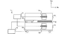
- FIG. 2 is a schematic view showing an example of the configuration of the IH device 1.
- the IH device 1 shown in FIG. 2 includes structural portions 11t and 11b, carts 12t and 12b, inductors 13t and 13b, a power supply 14, and a position controller 15.
- the structure portion 11t accommodates the inductor 13t. Structure 11t is moved in the width direction W SS within range of mechanical restrictions. Structurally portion 11t is moved, it changes the position of the inductor 13t in the width direction W SS. Movement of the structural unit 11t is, the position of the carriage 12t in the width direction W SS, the position controller 15 is performed by changing.
- the structure of the structural portion 11b is the same as that of the structural portion 11t.
- the configuration of the dolly 12b is the same as that of the dolly 12t.
- the configuration of the inductor 13b is the same as that of the inductor 13t.
- the structure of the structural portion 11b is the same as that of the structural portion 11t.
- the configuration of the dolly 12b is the same as that of the dolly 12t. Movement of the structural unit 11b, the position of the carriage 12b in the width direction W SS, the position controller 15 is performed by changing.
- the trolleys 12t and 12b are controlled independently by the position controller 15.
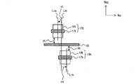
- FIG. 3 is a schematic view showing an example of the configuration of the inductors 13t and 13b.
- the inductor 13t includes an iron core 16t and a heating coil 17t.
- the inductor 13b includes an iron core 16b and a heating coil 17b.
- An alternating current is supplied to the heating coils 17t and 17b from the power supply 14 shown in FIG.
- an interlinkage magnetic flux is generated in the TH SS in the thickness direction of the steel material SS.
- the interlinkage magnetic flux induces eddy currents in the steel SS. Joule heat is generated by this eddy current, and the steel SS is heated.
- the reference position for use position of the center line L SS in various controls is also referred to as "shift".
- the distance from the center line L SS to the axis L 16t of the core 16t xt, and the distance xb from the center line L SS to the axis L 16b of the iron core 16b is also referred to as "shift".
- the distances xt and xb change.
- the distances xt and xb do not have to match.
- the distance in the thickness direction TH SS from steel SS to core 16t yt, and the distance yb in the thickness direction TH SS from steel SS to core 16b may not match.
- FIG. 4 is a schematic view showing an example of the arrangement of the IH device 1.
- FIG. 4 describes an example of the arrangement of the inductor 13t.
- the example of the arrangement of the inductor 13b is basically the same as that of the inductor 13t. Therefore, the description of the example of the arrangement of the inductor 13b will be omitted.
- the inductor 13t are arranged along the conveying direction DE SS steel SS.
- the transport direction DE SS is a direction orthogonal to the width direction W SS.
- Inductor 13t_ # 1 corresponds to the "top inductor” located most upstream in the conveying direction DE SS.
- the inductor 13t_ # 2 is located downstream of the inductor 13t_ # 1.
- Inductor 13t_ # N IH corresponds to "final inductor" located most downstream in the conveying direction DE SS.
- the operator's private room (that is, the pulpit) side provided in the rolling line 2 is referred to as an operator side OS.
- the other side of this private room is called the drive side DS.
- the inductor 13t_ # 1 is located on the drive side DS.
- Inductor 13t_ # N IH is located operator side OS.
- thermometer 3 is provided upstream of the leading inductor.
- the thermometer 3 measures the actual temperature of the surface of the node ND_ # i of the steel material SS as the “inside actual temperature Tei mes ” (however, i satisfies 1 ⁇ i ⁇ N ND ).
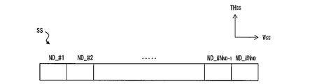
- FIG. 5 is a schematic diagram showing an example of the node ND.
- N ND-number of nodes ND_ # i is set along the width direction W SS. Therefore, data entry side actual temperature Tei meas constitutes the temperature distribution DerutaTei meas information steel SS in the width direction W SS.
- the thermometer 3 sends information on the temperature distribution ⁇ Tei meas to the computer 4.
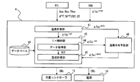
- FIG. 6 is a block diagram illustrating an example of the configuration of the functions of the computer 4. As shown in FIG. 6, the computer 4 includes a temperature calculation unit 41, an induction heating control unit (hereinafter, also referred to as “IH control unit”) 42, and a database 43. Some or all of these functions are realized by the processor of the computer 4 executing various programs stored in the memory.
- IH control unit induction heating control unit
- the temperature calculation unit 41 calculates the temperature distribution ⁇ T of the steel material SS in each step of the rolling process.
- the rolling command information MIL and the actual temperature information TEM are used for the calculation of the temperature distribution ⁇ T.
- the rolling instruction information MIL includes data of the steel grade Gp, width Wp and thickness THp of the final product.
- the rolling instruction information MIL also includes data of a target width W tgt and a target thickness TH tgt of the steel material SS in each process.
- the rolling command information MIL further includes data on the target temperature FDT of the steel material SS on the exit side of the finishing rolling mill 23 and data on the target temperature CT of the steel material SS before winding by the winder 25.
- the actual temperature information TEM includes information of the temperature distribution ⁇ Tei meas.
- the temperature calculation unit 41 sets the target temperature of the node ND_ # i (1 ⁇ i ⁇ N ND ) downstream of the final inductor as “outside target temperature Tdi tgt ”, for example, based on the target temperature FDT and CT data. calculate.
- Data outgoing side target temperature Tdi tgt constitutes information of the temperature distribution DerutaTdi tgt steel SS in the width direction W SS.
- the temperature calculation unit 41 may calculate the exit side target temperature Tdi tgt based on the data input from the operator.
- the temperature calculation unit 41 may calculate the output side target temperature Tdi tgt based on the data of the target temperature FDT and CT and the data input from the operator.
- the temperature calculation unit 41 sends information on the temperature distribution ⁇ Tdi tgt to the IH control unit 42.
- the temperature calculation unit 41 also calculates the predicted temperature of the steel material SS at the heating start position of the steel material SS by the IH device 1 as the “inside predicted temperature Tei calf ” based on the information of the temperature distribution ⁇ Tei meas. As the heating start position, the position of the leading inductor is exemplified. Data entry side predicted temperature Tei calf constitutes information of the temperature distribution DerutaTei calf steel SS in the width direction W SS. The temperature calculation unit 41 sends information on the temperature distribution ⁇ Tei calf to the IH control unit 42.
- the IH control unit 42 controls the IH device 1 by setting each power supplied to the inductors 13t and 13b and each shift of the inductors 13t and 13b.
- the IH control unit 42 includes a data acquisition unit 44 and a setting calculation unit 45.
- the data acquisition unit 44 acquires information from the temperature calculation unit 41.
- the information from the temperature calculation unit 41 includes information on the temperature distribution ⁇ Tdi tgt and information on the temperature distribution ⁇ Tei calf .
- the data acquisition unit 44 also acquires information from the database 43.
- the information from the database 43 includes model parameters and data tables for various controls in the rolling process.
- the data acquired by the data acquisition unit 44 constitutes the setting calculation information SET.
- the data acquisition unit 44 sends the setting calculation information SET to the setting calculation unit 45.
- the setting calculation unit 45 performs a "setting calculation process" for calculating the optimum power command value CMp and the optimum shift command value CMx based on the setting calculation information SET. For details of the setting calculation process, see Item 2-2. Explained in.
- the setting calculation unit 45 sends the power command value CMp to the power supply 14.
- the setting calculation unit 45 sends the shift command value CMx to the position controller 15.
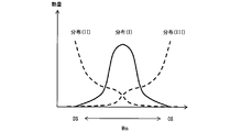
- the amount of heat to be introduced from the IH device 1 in steel SS is a diagram showing an example of the distribution in the width direction W SS of.
- Distribution (I) is an example of distribution when the distances xt and xb are 0 mm (ie, when the shift is 0 mm).
- the distribution of heat quantity changes from the distribution (I) to the distribution (II).
- the distribution of heat quantity changes from distribution (I) to distribution (III). In this way, changing the shift changes the tendency of heat distribution.
- the distribution of heat amount itself changes depending on the design of the inductor and the like.
- the setting calculation unit 45 performs the setting calculation process.
- the details of the setting calculation process will be described.
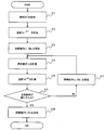
- FIG. 8 is a flowchart illustrating a flow of the setting calculation process according to the first embodiment. The routine shown in FIG. 8 is repeatedly executed by the processor of the computer 4 at predetermined cycles.
- the setting calculation information SET is acquired (step S11).
- the setting calculation information SET is information from the temperature calculation unit 41 and the database 43 described above.
- the predicted entry temperature Tei calf is calculated (step S12).
- the incoming side predicted temperature Tei calf is calculated based on, for example, the data of the incoming side actual temperature Tei meas and the amount of heat released from the installation position of the thermometer 3 to the heating start position. This heat dissipation amount is calculated based on model parameters such as the arrival time from the installation position to the heating start position, the thickness and width of the steel material, and the steel grade Gp.
- the initial values INxj and INpj are set (step S13).
- the initial value INxj is the initial value of the inductor 13t and 13b shifts located j-th in the conveying direction DE SS (although, j satisfies 1 ⁇ j ⁇ N IH).
- the initial value INpj is the initial value of the power supplied to the inductor 13t and 13b located j-th (where, j satisfies 1 ⁇ j ⁇ N IH).
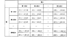
- FIG. 9 is an example of a data table showing a combination of initial values INxj and INpj.
- the thickness segment is divided into N TH pieces
- the width segment is divided into N W pieces, based on the combination of the initial value INxj and INpj (x mn_k, p mn_k) is It is set (however, m satisfies 1 ⁇ m ⁇ N W , n satisfies 1 ⁇ n ⁇ N TH , and k satisfies 1 ⁇ k ⁇ NIH ).
- the thickness division and the width division are set based on the data of the width Wp and the thickness THp.
- the combinations (x mn_k , pmn_k ) referenced by the table are used only as initial values in the setting calculation process. Therefore, the number N TH and N W may be small. Further, the classification based on the data of the steel grade Gp, the target temperature FDT, and the target temperature CT may be added to the classification shown in FIG.
- step S14 NoboriAtsushiryou QTij the j-th node by the IH device 1 (1 ⁇ j ⁇ N IH) ND_ # i (1 ⁇ i ⁇ N ND) is calculated (step S14).
- the calculation of the temperature rise amount QTij is calculated using the temperature rise amount model. For an example of the temperature rise model and an example of calculation of the temperature rise QTij, see Item 2-2-2. Explained in.
- the data of the temperature rise amount QTij constitutes information of the distribution ⁇ Tij indicating the amount of change in temperature on the surface of the steel material SS when the steel material SS is heated by the IH device 1.
- the predicted temperature of the steel material SS at the heating end position of the steel material SS by the IH device 1 is calculated as “outside predicted temperature Tdi cal ” (step S15).
- the position of the final inductor is exemplified as the heating end position.
- the exit side predicted temperature Tdi cal is the following formula showing the sum of the data of the input side predicted temperature Tei calf and the temperature change amount obtained by adding the data of the temperature rise amount QTij for the number of IH devices 1. Calculated based on 1).
- the x j min shown in the equation (1) is the lower limit constraint of the shift of the inductor located at the jth position, and the x j max is the upper limit constraint of the shift.
- p j min is the lower limit constraint of the electric power supplied to the inductor located at the jth position
- p j max is the upper limit constraint of the electric power.
- step S15 it is determined whether or not the convergence condition is satisfied for the predicted output temperature Tdi cal calculated in step S15 (step S16). Judgment as to whether or not the convergence condition is satisfied is performed using the evaluation function obj defined by the following equation (2).
- W j shown in the equation (2) is a weighting coefficient for the node ND_ # i (1 ⁇ i ⁇ N ND).
- the convergence condition includes, for example, that the evaluation function fobj is less than the threshold value.
- a combination of candidate values CAxj and CApj (x mn_k , pmn_k ) is set (step S17), and the processes of steps S14 to S16 are performed.
- the candidate value CAxj is a candidate value for shifting the inductor located at the jth position.
- the candidate value CApj is a candidate for the power supplied to the inductor located at the jth position.
- the convergence condition includes that the number of repetitions of the processes of steps S14 to S17 has reached the upper limit.
- the evaluation function fobj is less than the threshold value, or when the number of repetitions of the processes of steps S14 to S17 reaches the upper limit, it is determined that the convergence condition is satisfied.
- the optimum values OPx and OPp are determined (step S18).
- the optimum value OPx is a shift command value CMx input to the position controller 15.
- the optimum value OPp is a power command value CMp input to the power supply 14.
- the optimum values OPx and OPp are determined in consideration of the determination contents in step S16. Specifically, when it is determined that the evaluation function obj is less than the threshold value, the combinations (x mn_k , pmn_k ) used in the calculation of the evaluation function obj are adopted as the optimum values OPx and OPp. .. When it is determined that the number of repetitions has reached the upper limit, the combinations (x mn_k , pmn_k ) used in the calculation when the evaluation function obj is minimized are adopted as the optimum values OPx and OPp.
- FIG. 10 is a schematic diagram showing an example of a temperature rise amount model.
- a machine learning model is used as the temperature rise amount model.
- a machine learning model is constructed by a neural network composed of an input layer IPT, an intermediate layer MID, and an output layer OPT.
- the heating factor of the steel material SS is input to the input layer IPT. Examples of the heating factor include a steel grade Gp, a width Wp, a thickness THp, an exit target temperature Tdi tgt, and an entry side actual temperature Tei meas .
- a case study for various heating factors is carried out in advance by numerical analysis of a three-dimensional magnetic field and heat quantity by a finite element method or the like.
- the surface temperature at the node ND_ # i at the heating end position is determined in each case.
- this temperature is teacher data, a machine learning model is constructed.
- the setting calculation process is performed to determine the optimum values OPx and OPp.
- iterative calculation using the evaluation function obj is performed.
- the variable of the evaluation function obj the predicted output temperature Tdi cal is used (see equation (2)).
- the temperature rise amount QTij calculated using the temperature rise amount model is used (see equation (1)). Then, in the calculation of the temperature rise amount QTij, the combination of the candidate values CAxj and CApj is taken into consideration. Therefore, according to the control of the IH device 1 performed based on the optimum value OPx and OPp, it becomes possible to uniform the temperature distribution ⁇ T of steel SS in the width direction W SS in the heating end position.
- the input side predicted temperature Tei calf is used as the variable of the exit side predicted temperature Tdi cal (see equation (1)).
- the data of the incoming side actual temperature Tei meas is used for the calculation of the incoming side predicted temperature Tei calf. That is, the incoming side actual temperature Tei meas is taken into consideration in the calculation of the incoming side predicted temperature Tei calf. Therefore, it is possible to improve the accuracy of the prediction of the output side predicted temperature Tdi cal and to improve the reliability of the optimum values OPx and OPp. Therefore, it is possible to increase the reliability of the control of the IH device 1 performed based on the optimum values OPx and OPp.
- FIG. 11 is a schematic diagram showing the configuration of a hot rolling facility to which the IH system according to the second embodiment is applied.
- the induction heating method according to the second embodiment is realized by the IH system described below.
- the hot rolling equipment includes an IH device 1, a rolling line 2, a computer 4, and a thermometer 5.
- the IH device 1, the computer 4, and the thermometer 5 constitute the IH system according to the second embodiment.
- the thermometer 5 is provided downstream of the final inductor.
- Thermometer 5 the actual temperature of the surface at the node ND_ # i of steel SS, measured as "exit-side actual temperature Tdi meas" (1 ⁇ i ⁇ N ND) .
- the concept of node ND_ # i is as described in FIG.
- Data outgoing side actual temperature Tdi meas constitutes the temperature distribution DerutaTdi meas information steel SS in the width direction W SS.
- Thermometer 5 sends the information of the temperature distribution DerutaTdi meas the computer 4.
- FIG. 12 is a block diagram illustrating an example of the configuration of the functions of the computer 4. As shown in FIG. 12, the computer 4 includes a temperature calculation unit 41, an IH control unit 42, a database 43, and a temperature distribution prediction unit 46. Some or all of these functions are realized by the processor of the computer 4 executing various programs stored in the memory.
- the function of the temperature calculation unit 41 is basically the same as that in the first embodiment. However, in the second embodiment, the temperature calculation unit 41 calculates the predicted temperature of the steel material SS at the heating start position as “ inside predicted temperature Tei cals”. The inlet side to the calculation of the predicted temperature Tei cals, other information is used as the temperature distribution DerutaTei meas information. Note that the temperature distribution DerutaTei meas information is information used for the calculation of the ingress predicted temperature Tei calf in the first embodiment.
- This other information consists of surface temperature data at node ND_ # i measured or predicted upstream of the lead inductor, such as surface temperature data at node ND_ # i on the exit side of the rough rolling mill 22.
- the information to be given is exemplified.
- Data entry side predicted temperature Tei cals constitutes information of the temperature distribution DerutaTei cals steel SS in the width direction W SS.
- the temperature calculation unit 41 sends information on the temperature distribution ⁇ Tei cals to the temperature distribution prediction unit 46.
- the function of the IH control unit 42 is basically the same as that in the first embodiment. That is, the IH control unit 42 (setting calculation unit 45) performs the setting calculation process based on the setting calculation information SET. However, in the second embodiment, the IH controller 42 (setting calculation unit 45), the information of the temperature distribution DerutaTdi cal used as variables of the evaluation function obj when optimum values OPx and OPp is employed, the prediction temperature distribution Send to department 46.
- Temperature distribution predicting unit 46 the temperature distribution ⁇ T of steel SS in the width direction W SS in the heating start position is calculated as a "temperature distribution DerutaTei Recal”.
- the temperature distribution ⁇ Tei recal is composed of data of the repredicted temperature of the steel material SS in the width direction WSS at the heating start position (hereinafter, also referred to as “inside repredicted temperature Tei recal”).
- Entry side again predicted temperature Tei Recal is, specifically, the data entry side predicted temperature Tei cals, is calculated based on the equation showing the sum of the deviation T error (formula (3)).
- Deviation T error is immediately before the heating of the steel SS by IH device 1, and the data output side predicted temperature Tdi cal another steel SS heated by the IH unit 1, exit side actual temperature of the different steel SS It is calculated based on the data of Tdi meas.
- this time material SSB the steel material SS located upstream of the heating start position and to be heated by the IH device 1
- previous material SSA The steel material SS located downstream of the heating end position and heated by the IH device 1 immediately before the material SSB this time.
- ⁇ shown in the formula (3) is a coefficient representing the influence of the previous material SSA on the current material SSB.
- Data outgoing side actual temperature Tdi meas represented by formula (4) is included in the temperature distribution DerutaTdi meas information of the previous material SSA input from the temperature calculation section 41.
- the data of the output side predicted temperature Tdi cal is included in the information of the temperature distribution ⁇ Tdi cal of the previous material SSA input from the setting calculation unit 45.
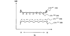
- FIG. 13 is a schematic diagram showing an example of the relationship between the temperature distributions ⁇ Tdi cal and ⁇ T di meas of the previous material SSA and the temperature distributions Tei cals and ⁇ Tei recal of the current material SSB.
- the IH system according to the first embodiment the information of the temperature distribution DerutaTei meas is obtained from the thermometer 3.
- the IH system according to the second embodiment is not provided with the thermometer 3. Therefore, when comparing these systems, it is assumed that the accuracy of the prediction of the temperature distribution ⁇ Tei cals is low in the second embodiment.
- the prediction information of the temperature distribution of the previous material SSA downstream of the final inductor that is, the information of the temperature distribution ⁇ Tdi cal of the previous material SSA
- the result information that is, the temperature distribution ⁇ Tdi of the previous material SSA.
- FIG. 14 is a flowchart illustrating a flow of the setting calculation process according to the second embodiment.
- the routine shown in FIG. 14 is executed after the end of heating of the previous material SSA by the IH device 1 and before the start of heating of the material SSB this time.
- the processes of steps S11 and S13 to S18 shown in FIG. 14 are as described in FIG. Therefore, in the following, the contents of the processing of the steps other than these steps will be described.
- the predicted entry temperature Tei cals is calculated (step S21).
- the incoming predicted temperature Tei cals is calculated, for example, based on the data constituting the above-mentioned "other information".
- the data constituting the "other information” is the data of the actual temperature of the surface at the node ND_ # i on the exit side of the rough rolling mill 22.
- the input side predicted temperature Tei is based on the amount of heat radiated from the position of the thermometer installed on the outlet side of the rough rolling mill 22 to the heating start position and the actual temperature data sent from the thermometer. cals are calculated.
- step S22 the deviation Terror is calculated (step S22). Calculation of the deviation T error is performed by inputting the data output side predicted temperature Tdi cal previous material SSA, and the exit-side actual temperature Tdi meas of the previous material SSA data to equation (4).
- step S23 the incoming repredicted temperature Tei recal is calculated (step S23).
- Calculation of the inlet side re predicted temperature Tei Recal is performed by inputting the deviation T error calculated in step S22, the data of the ingress predicted temperature Tei cals of this material SSB in equation (3).
- thermometer 3 that is, the thermometer 3 shown in FIG. 1
- the entrance side is provided.
- the calculation of the incoming re-predicted temperature Tei recal performed using data different from the data of the actual temperature Tei meas compensates for the decrease in the prediction accuracy of the incoming predicted temperature Tei cals. Therefore, according to the IH system according to the second embodiment, it is possible to obtain the same effect as that according to the first embodiment.
Landscapes
- Engineering & Computer Science (AREA)
- Mechanical Engineering (AREA)
- General Induction Heating (AREA)
- Control Of Heat Treatment Processes (AREA)
- Control Of Metal Rolling (AREA)
Abstract
誘導加熱方法は、鋼材を加熱する複数のインダクタのそれぞれに供給される電力と、前記複数のインダクタのそれぞれの位置と、の組み合わせを設定するステップを含む。前記組み合わせを設定するステップは、入側予測温度(Teicalf,Teicals)を計算するステップ(S12)と、前記組み合わせの候補を設定するステップ(S13,S16,S17)と、前記候補が採用された場合における昇温量(QTij)を、機械学習モデルを用いて予測するステップ(S14)と、出側予測温度(Tdical)を計算するステップ(S15)と、前記出側予測温度(Tdical)および出側目標温度(Tditgt)を変数とする評価関数が閾値未満となるときの前記候補、または、前記評価関数が最小となるときの前記候補を、前記組み合わせとして採用するステップ(S18)と、を含む。
Description
本発明は、熱間圧延プロセスにおいて鋼材を誘導加熱方式により加熱する方法およびシステムに関する。
一般的に、熱間圧延プロセスを経て製造される鋼材の機械的性質は、当該プロセス中の鋼材の温度と関係が強い。そのため、熱間圧延プロセスにおける鋼材の温度制御は、製品の品質向上の観点から重要である。
近年では、多くの熱間圧延ラインに誘導加熱装置(以下、「IH装置」とも称す。)が導入されている。IH装置の導入によれば、サーマルランダウンが抑制される。サーマルダウンとは、主に薄い鋼材の製造時に仕上圧延機の入側において尾端部に向かうほど当該鋼材の温度が低下する現象である。また、加熱炉内でスラブを支える支柱(スキッド)への抜熱による鋼材の長手方向の温度ムラの発生も低減される。更に、硬い高級鋼材の製造時において、仕上圧延の前で圧延材を昇温することで圧延荷重が下がり、通板性が改善され、また、仕上圧延機の負担も軽減される。
更に、IH装置の導入によれば、鋼材の局所的な加熱が可能となる。鋼材の尾端部の加熱による昇温は、尾端絞りの発生を抑制する効果がある。尾端絞りとは、尾端部が仕上圧延機を抜ける際に蛇行し、装置に接触することで座屈する現象である。鋼材の幅方向の端部は放熱により温度が低下しやすいため、加熱することにより、幅方向の温度分布が均一となる。そのため、幅方向の品質の向上が期待される。また、端部が加熱されると、粗大粒と整粒が混ざった組織(すなわち、混粒)や、割れが発生するのを抑えることが可能となる。また、仕上圧延機のロールの扁摩耗等を抑える効果も期待される。
IH装置は、鋼材に鎖交する主磁束(すなわち、IH装置から発生した交流磁束)の方向により、ソレノイド方式とトランスバース方式の2種類に分類される。ソレノイド方式のIH装置では、主磁束の方向が鋼材の搬送方向と一致する。トランスバース方式のIH装置では、主磁束の方向が鋼材の厚さ方向と一致する。
トランスバース方式のIH装置に関する従来技術として、特許文献1および2が例示される。特許文献1および2は、搬送方向に沿って3台のIH装置が配列された例を開示する。特許文献1では、鋼材の幅方向におけるIH装置の重なり合い量が制御される。特許文献2では、幅方向におけるIH装置のコア間の距離が制御される。重なり合い量および距離の制御は、何れも、幅方向におけるIH装置の位置の変更により行われる。
しかしながら、特許文献1におけるIH装置の制御は、幅方向における鋼材の温度分布が左右対称であることを前提として行われる。そのため、この前提条件が満たされないときには、幅方向における温度分布を均一にすることが難しい。また、特許文献2におけるIH装置の制御において幅方向の端部の加熱については別途行われるエッジヒータの制御により担保される。そのため、幅方向における温度分布を均一にするには、IH装置とエッジヒータの制御を協調して実行する必要がある。
本発明は、上述の課題を解決するためになされたもので、幅方向における温度分布が左右対称でない場合においても、IH装置の制御の実行のみによって当該温度分布を均一にすることのできる技術を提供することを目的とする。
本発明は、トランスバース方式の誘導加熱方法であり、次の特徴を有する。
前記誘導加熱方法は、圧延ラインの搬送方向に設けられて鋼材を加熱する複数のインダクタのそれぞれに供給される電力と、前記搬送方向に対して直交する方向における前記複数のインダクタのそれぞれの位置と、の組み合わせを設定するステップを含む。
前記組み合わせを設定するステップは、
前記複数のインダクタによる前記鋼材の加熱開始位置での前記直交方向における前記鋼材の複数の区分のそれぞれの予測温度を示す入側予測温度を計算するステップと、
前記組み合わせの候補を設定するステップと、
前記候補が採用された場合における前記複数の区分のそれぞれの昇温量を、機械学習モデルを用いて予測するステップと、
前記入側予測温度と、前記昇温量とに基づいて、前記複数のインダクタによる前記鋼材の加熱終了位置での前記複数の区分のそれぞれの予測温度を示す出側予測温度を計算するステップと、
前記出側予測温度と、前記加熱終了位置での前記複数の区分のそれぞれの目標温度を示す出側目標温度と、を変数とする評価関数が閾値未満となるときの前記候補、または、前記評価関数が最小となるときの前記候補を、前記組み合わせとして採用するステップと、
を含む。
前記誘導加熱方法は、圧延ラインの搬送方向に設けられて鋼材を加熱する複数のインダクタのそれぞれに供給される電力と、前記搬送方向に対して直交する方向における前記複数のインダクタのそれぞれの位置と、の組み合わせを設定するステップを含む。
前記組み合わせを設定するステップは、
前記複数のインダクタによる前記鋼材の加熱開始位置での前記直交方向における前記鋼材の複数の区分のそれぞれの予測温度を示す入側予測温度を計算するステップと、
前記組み合わせの候補を設定するステップと、
前記候補が採用された場合における前記複数の区分のそれぞれの昇温量を、機械学習モデルを用いて予測するステップと、
前記入側予測温度と、前記昇温量とに基づいて、前記複数のインダクタによる前記鋼材の加熱終了位置での前記複数の区分のそれぞれの予測温度を示す出側予測温度を計算するステップと、
前記出側予測温度と、前記加熱終了位置での前記複数の区分のそれぞれの目標温度を示す出側目標温度と、を変数とする評価関数が閾値未満となるときの前記候補、または、前記評価関数が最小となるときの前記候補を、前記組み合わせとして採用するステップと、
を含む。
前記入側予測温度を計算するステップにおいて、前記入側予測温度は、前記加熱開始位置よりも上流における前記鋼材の各区分の実温度を示す入側実温度に基づいて計算されてもよい。
前記鋼材は、前記加熱開始位置の上流に位置する今回材と、前記加熱終了位置の下流に位置し、前記複数のインダクタによる前記今回材の加熱の直前にこれらのインダクタによって加熱された前回材と、を含んでもよい。
前記組み合わせを設定するステップは、前記前回材の前記出側予測温度と、前記加熱終了位置よりも下流における前記前回材の各区分の実温度を示す出側実温度との偏差を計算するステップを更に含んでいてもよい。
前記入側予測温度を計算するステップにおいて、前記入側予測温度は、前記加熱開始位置よりも上流における前記今回材の複数の区分のそれぞれの温度と、前記偏差と、に基づいて計算されてもよい。
前記組み合わせを設定するステップは、前記前回材の前記出側予測温度と、前記加熱終了位置よりも下流における前記前回材の各区分の実温度を示す出側実温度との偏差を計算するステップを更に含んでいてもよい。
前記入側予測温度を計算するステップにおいて、前記入側予測温度は、前記加熱開始位置よりも上流における前記今回材の複数の区分のそれぞれの温度と、前記偏差と、に基づいて計算されてもよい。
本発明は、トランスバース方式の誘導加熱システムであり、次の特徴を有する。
前記誘導加熱システムは、
圧延ラインの搬送方向に設けられて鋼材を加熱する複数のインダクタと、
前記複数のインダクタのそれぞれに供給される電力と、前記搬送方向に対して直交する方向における前記複数のインダクタのそれぞれの位置と、に基づいて、前記直交方向における前記鋼材の複数の区分の温度を制御する制御装置と、
を備える。
前記制御装置は、前記電力と前記位置の組み合わせを設定する設定計算処理を行う。
前記制御装置は、前記設定計算処理において、
前記複数のインダクタによる前記鋼材の加熱開始位置での前記複数の区分のそれぞれの予測温度を示す入側予測温度を計算し、
前記組み合わせの候補を設定し、
前記候補が採用された場合における前記複数の区分のそれぞれの昇温量を、機械学習モデルを用いて予測し、
前記入側予測温度と、前記昇温量とに基づいて、前記複数のインダクタによる前記鋼材の加熱終了位置での前記複数の区分のそれぞれの予測温度を示す出側予測温度を計算し、
前記出側予測温度と、前記加熱終了位置での前記複数の区分のそれぞれの目標温度を示す出側目標温度と、を変数とする評価関数が閾値未満となるときの前記候補、または、前記評価関数が最小となるときの前記候補を、前記組み合わせとして採用する。
前記誘導加熱システムは、
圧延ラインの搬送方向に設けられて鋼材を加熱する複数のインダクタと、
前記複数のインダクタのそれぞれに供給される電力と、前記搬送方向に対して直交する方向における前記複数のインダクタのそれぞれの位置と、に基づいて、前記直交方向における前記鋼材の複数の区分の温度を制御する制御装置と、
を備える。
前記制御装置は、前記電力と前記位置の組み合わせを設定する設定計算処理を行う。
前記制御装置は、前記設定計算処理において、
前記複数のインダクタによる前記鋼材の加熱開始位置での前記複数の区分のそれぞれの予測温度を示す入側予測温度を計算し、
前記組み合わせの候補を設定し、
前記候補が採用された場合における前記複数の区分のそれぞれの昇温量を、機械学習モデルを用いて予測し、
前記入側予測温度と、前記昇温量とに基づいて、前記複数のインダクタによる前記鋼材の加熱終了位置での前記複数の区分のそれぞれの予測温度を示す出側予測温度を計算し、
前記出側予測温度と、前記加熱終了位置での前記複数の区分のそれぞれの目標温度を示す出側目標温度と、を変数とする評価関数が閾値未満となるときの前記候補、または、前記評価関数が最小となるときの前記候補を、前記組み合わせとして採用する。
前記誘導加熱システムは、前記加熱開始位置よりも上流に設けられ、前記鋼材の各区分の実温度を示す入側実温度を計測する入側温度計を更に備えていてもよい。
前記制御装置は、前記設定計算処理において、前記入側実温度に基づいて前記入側予測温度を計算してもよい。
前記制御装置は、前記設定計算処理において、前記入側実温度に基づいて前記入側予測温度を計算してもよい。
前記誘導加熱システムは、前記加熱終了位置よりも下流に設けられ、前記鋼材の各区分の実温度を示す出側実温度を計測する出側温度計を更に備えていてもよい。
前記鋼材は、前記加熱開始位置の上流に位置する今回材と、前記加熱終了位置の下流に位置し、前記複数のインダクタによる前記今回材の加熱の直前にこれらのインダクタによって加熱された前回材と、を含んでもよい。
前記制御装置は、前記設定計算処理において、
前記前回材の前記出側予測温度と、前記前回材の前記出側実温度との偏差を計算し、
前記加熱開始位置よりも上流における前記今回材の複数の区分のそれぞれの温度と、前記偏差と、に基づいて、前記入側予測温度を計算してもよい。
前記鋼材は、前記加熱開始位置の上流に位置する今回材と、前記加熱終了位置の下流に位置し、前記複数のインダクタによる前記今回材の加熱の直前にこれらのインダクタによって加熱された前回材と、を含んでもよい。
前記制御装置は、前記設定計算処理において、
前記前回材の前記出側予測温度と、前記前回材の前記出側実温度との偏差を計算し、
前記加熱開始位置よりも上流における前記今回材の複数の区分のそれぞれの温度と、前記偏差と、に基づいて、前記入側予測温度を計算してもよい。
本発明に係る誘導加熱方法によれば、複数のインダクタのそれぞれに供給される電力と、複数のインダクタのそれぞれの位置と、の組み合わせが設定される。組み合わせの設定に際しては、鋼材の加熱開始位置での搬送方向に対して直交する方向(すなわち、幅方向)における鋼材の複数の区分のそれぞれの予測温度(すなわち、入側予測温度)が計算される。また、組み合わせの候補が設定される。更に、この候補が採用された場合における複数の区分のそれぞれの昇温量が、機械学習モデルを用いて予測される。また更に、計算された入側予測温度と、予測された昇温量とに基づいて、鋼材の加熱終了位置での複数の区分のそれぞれの予測温度(すなわち、出側予測温度)が計算される。
そして、出側予測温度と、加熱終了位置での複数の区分のそれぞれの目標温度(すなわち、出側目標温度)と、を変数とする評価関数が閾値未満となるときの候補、または、当該評価関数が最小となるときの候補が、電力と位置の組み合わせとして採用される。このように、本発明に係る誘導加熱方法によれば、入側予測温度と昇温量を考慮して計算された出側予測温度と、出側目標温度とを変数とする評価関数を利用して、適切な電力と位置の組み合わせを決定することが可能となる。そのため、幅方向における温度分布が左右対称でない場合においても、インダクタの制御の実行のみによって加熱終了位置での当該温度分布を均一にすることが可能となる。
本発明に係る誘導加熱システムによれば、電力と位置の組み合わせを設定する設定計算処理が行われる。設定計算処理によれば、入側予測温度と昇温量を考慮して計算された出側予測温度と、出側目標温度とを変数とする評価関数を利用して、適切な電力と位置の組み合わせを決定することが可能となる。したがって、幅方向における温度分布が左右対称でない場合においても、インダクタの制御の実行のみによって加熱終了位置での当該温度分布を均一にすることが可能となる。
第1実施形態
まず、図1~10を参照して本発明の第1実施形態について詳細に説明する。
まず、図1~10を参照して本発明の第1実施形態について詳細に説明する。
1.システム構成
1-1.熱間圧延設備の構成
図1は、第1実施形態に係る誘導加熱システム(以下、「IHシステム」とも称す。)が適用される熱間圧延設備の構成の一例を示す概略図である。なお、第1実施形態に係る誘導加熱方法は、第1実施形態に係るIHシステムにより実現される。
1-1.熱間圧延設備の構成
図1は、第1実施形態に係る誘導加熱システム(以下、「IHシステム」とも称す。)が適用される熱間圧延設備の構成の一例を示す概略図である。なお、第1実施形態に係る誘導加熱方法は、第1実施形態に係るIHシステムにより実現される。
熱間圧延設備は、圧延材としての鋼材SSを、所望の厚さおよび幅を有する最終製品へと加工するための設備である。図1に示されるように、熱間圧延設備は、IH装置1と、圧延ライン2と、計算機4と、温度計3と、を備えている。IH装置1と、計算機4と、温度計3とは、第1実施形態に係るIHシステムを構成する。これらの構成については項目1-2.で説明される。以下では、圧延ライン2の構成について説明される。
圧延ライン2は、加熱炉21と、粗圧延機22と、仕上圧延機23と、冷却テーブル24と、巻取機25と、を備える。加熱炉21は、圧延ライン2の上流に設けられる。加熱炉21は、鋼材SSを所定温度(例えば、約1200℃)まで加熱する。加熱炉21からは、直方体状の鋼材SSが抽出される。加熱炉21から抽出された鋼材SSは、例えば、200~250mmの厚さ、800~2000mmの幅および5~12mの長さを有している。
粗圧延機22は、加熱炉21の下流に設けられる。粗圧延機22は、1~3基の圧延スタンドを備えている。粗圧延機22では、圧延ライン2の上流から下流に向かう順方向の圧延と、当該下流から当該上流に向かう逆方向の圧延と、が交互に複数回行われる。つまり、鋼材SSは、粗圧延機22を複数回往復する。これにより、鋼材SSの厚さは所定の厚さまで減少する。粗圧延機22には、鋼材SSの幅を調整するエッジャと呼ばれる装置が付属されていてもよい。
仕上圧延機23は、IH装置1の下流に設けられる。仕上圧延機23は、複数の圧延スタンド(例えば7基)を備えている。仕上圧延機23は、圧延ロール、支持ロール等の装置を圧延スタンドごとに有している。仕上圧延機23では、圧延ライン2の上流から下流へと向かう一方向の圧延が行われる。これにより、鋼材SSの厚さは製品厚まで減少する。仕上圧延の最中、鋼材SSの温度は、圧延ロールとの接触や冷却水の噴射により低下する。仕上圧延機23の出側における鋼材SSの温度は、普通鋼の場合、例えば、約900℃である。
冷却テーブル24は、仕上圧延機23の下流に設けられる。冷却テーブル24は、冷却バンクと呼ばれる水冷却装置(図示しない)を備えている。冷却テーブル24は、この冷却バンクから冷却水を噴射して鋼材SSの温度を下げる。
巻取機25は、冷却テーブル24の下流に設けられる。巻取機25は、鋼材SSをコイル状に巻き取る。巻取機25で巻き取られる前の鋼材SSの温度は、普通鋼の場合は600℃前後である。特殊鋼の場合などでは、この温度が200℃程度となることもある。
1-2.IHシステムの構成
1-2-1.IH装置
IH装置1は、トランスバース方式のIH装置である。図2は、IH装置1の構成の一例を示す概略図である。図2に示されるIH装置1は、構造部11tおよび11bと、台車12tおよび12bと、インダクタ13tおよび13bと、電源14と、位置コントローラ15と、を備えている。
1-2-1.IH装置
IH装置1は、トランスバース方式のIH装置である。図2は、IH装置1の構成の一例を示す概略図である。図2に示されるIH装置1は、構造部11tおよび11bと、台車12tおよび12bと、インダクタ13tおよび13bと、電源14と、位置コントローラ15と、を備えている。
構造部11tは、インダクタ13tを収容する。構造部11tは、機械的な制約の範囲内において幅方向WSSに移動する。構造部11tが移動すると、幅方向WSSにおけるインダクタ13tの位置が変わる。構造部11tの移動は、幅方向WSSにおける台車12tの位置を、位置コントローラ15が変更することにより行われる。
構造部11bの構成は、構造部11tのそれと同じである。台車12bの構成は、台車12tのそれと同じである。インダクタ13bの構成は、インダクタ13tのそれと同じである。構造部11bの構成は、構造部11tのそれと同じである。台車12bの構成は、台車12tのそれと同じである。構造部11bの移動は、幅方向WSSにおける台車12bの位置を、位置コントローラ15が変更することにより行われる。なお、位置コントローラ15による台車12tおよび12bの制御は、独立して行われる。
図3は、インダクタ13tおよび13bの構成の一例を示す概略図である。図3に示されるように、インダクタ13tは、鉄心16tと、加熱コイル17tと、を備えている。インダクタ13bは、鉄心16bと、加熱コイル17bと、を備えている。加熱コイル17tおよび17bには、図2に示した電源14から交流電流が供給される。そうすると、鋼材SSの厚さ方向THSSに鎖交磁束が発生する。鎖交磁束は、鋼材SSに渦電流を誘起させる。この渦電流によりジュール熱が発生し、鋼材SSが加熱される。
ここで、幅方向WSSにおける鋼材SSの中心線LSSを考える。第1実施形態では、この中心線LSSの位置を各種制御で使用する基準位置とする。以下の説明では、中心線LSSから鉄心16tの軸線L16tまでの距離xt、および、中心線LSSから鉄心16bの軸線L16bまでの距離xbを「シフト」とも称す。位置コントローラ15による台車12tおよび12bの制御が行われると、距離xtおよびxbが変わる。距離xtおよびxbは、一致していなくてもよい。また、鋼材SSから鉄心16tまでの厚さ方向THSSにおける距離yt、および、鋼材SSから鉄心16bまでの厚さ方向THSSにおける距離ybは、一致していなくてもよい。
IH装置1は、合計NIH基設けられている。図4は、IH装置1の配置の一例を示す概略図である。図4では、インダクタ13tの配置の例を説明する。インダクタ13bの配置の例については、インダクタ13tのそれと基本的に同じである。そのため、インダクタ13bの配置の例の説明については省略される。
図4に示されるように、インダクタ13tは、鋼材SSの搬送方向DESSに沿って並べられている。搬送方向DESSは、幅方向WSSと直交する方向である。インダクタ13t_#1は、搬送方向DESSにおける最上流に位置する「先頭インダクタ」に該当する。インダクタ13t_#1の下流には、インダクタ13t_#2が位置している。インダクタ13t_#NIHは、搬送方向DESSにおける最下流に位置する「最終インダクタ」に該当する。
圧延ライン2に設けられるオペレータ用の個室(すなわち、パルピット)側は、オペレータサイドOSと称される。この個室の反対側は、ドライブサイドDSと称される。図4に示される例では、インダクタ13t_#1がドライブサイドDSに位置している。インダクタ13t_#NIHは、オペレータサイドOSに位置している。
1-2-2.温度計
温度計3は、先頭インダクタの上流に設けられる。温度計3は、鋼材SSのノードND_#iにおける表面の実温度を、「入側実温度Teimeas」として計測する(ただし、iは1≦i≦NNDを満たす)。図5は、ノードNDの一例を示す概略図である。図5に示される例では、NND個のノードND_#iが幅方向WSSに沿って設定されている。そのため、入側実温度Teimeasのデータは、幅方向WSSにおける鋼材SSの温度分布ΔTeimeasの情報を構成する。温度計3は、計算機4に温度分布ΔTeimeasの情報を送る。
温度計3は、先頭インダクタの上流に設けられる。温度計3は、鋼材SSのノードND_#iにおける表面の実温度を、「入側実温度Teimeas」として計測する(ただし、iは1≦i≦NNDを満たす)。図5は、ノードNDの一例を示す概略図である。図5に示される例では、NND個のノードND_#iが幅方向WSSに沿って設定されている。そのため、入側実温度Teimeasのデータは、幅方向WSSにおける鋼材SSの温度分布ΔTeimeasの情報を構成する。温度計3は、計算機4に温度分布ΔTeimeasの情報を送る。
1-2-3.計算機
計算機4は、典型的には、プロセッサ、メモリおよび入出力インタフェースを備えるコンピュータである。計算機4は、加熱炉21から抽出された鋼材SSが巻取機25によって巻き取られるまでの一連の圧延プロセスに関する計算処理を行う。図6は、計算機4の機能の構成の一例を説明するブロック図である。図6に示されるように、計算機4は、温度計算部41と、誘導加熱制御部(以下、「IH制御部」とも称す。)42と、データベース43と、を備えている。これらの機能の一部または全ては、計算機4のプロセッサがメモリに記憶されている各種のプログラムを実行することにより実現される。
計算機4は、典型的には、プロセッサ、メモリおよび入出力インタフェースを備えるコンピュータである。計算機4は、加熱炉21から抽出された鋼材SSが巻取機25によって巻き取られるまでの一連の圧延プロセスに関する計算処理を行う。図6は、計算機4の機能の構成の一例を説明するブロック図である。図6に示されるように、計算機4は、温度計算部41と、誘導加熱制御部(以下、「IH制御部」とも称す。)42と、データベース43と、を備えている。これらの機能の一部または全ては、計算機4のプロセッサがメモリに記憶されている各種のプログラムを実行することにより実現される。
温度計算部41は、圧延プロセスの各工程における鋼材SSの温度分布ΔTを計算する。温度分布ΔTの計算には、圧延命令情報MILおよび実温度情報TEMが利用される。圧延命令情報MILには、最終製品の鋼種Gp、幅Wpおよび厚さTHpのデータが含まれる。圧延命令情報MILには、また、各工程における鋼材SSの目標幅Wtgtおよび目標厚THtgtのデータが含まれる。圧延命令情報MILには、更に、仕上圧延機23の出側における鋼材SSの目標温度FDTのデータと、巻取機25による巻取り前の鋼材SSの目標温度CTのデータと、が含まれる。実温度情報TEMには、温度分布ΔTeimeasの情報が含まれる。
温度計算部41は、例えば、目標温度FDTおよびCTのデータに基づいて、最終インダクタの下流におけるノードND_#i(1≦i≦NND)の目標温度を、「出側目標温度Tditgt」として計算する。出側目標温度Tditgtのデータは、幅方向WSSにおける鋼材SSの温度分布ΔTditgtの情報を構成する。温度計算部41は、オペレータから入力されたデータに基づいて、出側目標温度Tditgtを計算してもよい。温度計算部41は、目標温度FDTおよびCTのデータと、オペレータから入力されたデータと、に基づいて、出側目標温度Tditgtを計算してもよい。温度計算部41は、温度分布ΔTditgtの情報をIH制御部42に送る。
温度計算部41は、また、温度分布ΔTeimeasの情報に基づいて、IH装置1による鋼材SSの加熱開始位置での鋼材SSの予測温度を、「入側予測温度Teicalf」として計算する。加熱開始位置としては、先頭インダクタの位置が例示される。入側予測温度Teicalfのデータは、幅方向WSSにおける鋼材SSの温度分布ΔTeicalfの情報を構成する。温度計算部41は、温度分布ΔTeicalfの情報をIH制御部42に送る。
IH制御部42は、インダクタ13tおよび13bに供給される各電力と、インダクタ13tおよび13bの各シフトと、を設定することによりIH装置1を制御する。IH装置1を制御するための構成として、IH制御部42は、データ取得部44と、設定計算部45と、を備えている。
データ取得部44は、温度計算部41からの情報を取得する。温度計算部41からの情報には、温度分布ΔTditgtの情報と、温度分布ΔTeicalfの情報と、が含まれる。データ取得部44は、また、データベース43からの情報を取得する。データベース43からの情報には、圧延プロセスにおける各種制御のためのモデルパラメータおよびデータテーブルが含まれる。データ取得部44が取得したデータは、設定計算情報SETを構成する。データ取得部44は、設定計算情報SETを設定計算部45に送る。
設定計算部45は、設定計算情報SETに基づいて、最適な電力指令値CMpと、最適なシフト指令値CMxと、を計算する「設定計算処理」を行う。設定計算処理の詳細については項目2-2.で説明される。設定計算部45は、電力指令値CMpを電源14に送る。設定計算部45は、シフト指令値CMxを位置コントローラ15に送る。
2.第1実施形態の特徴
2-1.問題点
図7は、IH装置1から鋼材SSに投入される熱量(すなわち、鋼材SSの昇温量)の幅方向WSSにおける分布の一例を示した図である。分布(I)は、距離xtおよびxbが0mmのとき(すなわち、シフトが0mmのとき)の分布の例である。構造部11tおよび11bの位置をドライブサイドDSに移動させると、熱量の分布は、分布(I)から分布(II)へと変化する。これらの位置をオペレータサイドOSに移動させると、熱量の分布は分布(I)から分布(III)へと変化する。このように、シフトを変えると熱量の分布の傾向が変化する。なお、熱量の分布自体は、インダクタの設計等に応じても変化する。
2-1.問題点
図7は、IH装置1から鋼材SSに投入される熱量(すなわち、鋼材SSの昇温量)の幅方向WSSにおける分布の一例を示した図である。分布(I)は、距離xtおよびxbが0mmのとき(すなわち、シフトが0mmのとき)の分布の例である。構造部11tおよび11bの位置をドライブサイドDSに移動させると、熱量の分布は、分布(I)から分布(II)へと変化する。これらの位置をオペレータサイドOSに移動させると、熱量の分布は分布(I)から分布(III)へと変化する。このように、シフトを変えると熱量の分布の傾向が変化する。なお、熱量の分布自体は、インダクタの設計等に応じても変化する。
IH装置1による加熱後の幅方向WSSにおける温度分布を均一にする手法として、事前の検討に基づいたデータテーブル等の用意が挙げられる。この手法では、最終製品の幅Wpおよび厚さTHpのデータを考慮して、NIH基のIH装置1のそれぞれのシフトが事前に設定される。しかしながら、この手法では、加熱開始位置での幅方向WSSにおける温度分布の変化を考慮することができない。そのため、この温度分布が事前検討のときのそれと異なると、IH装置1による加熱後の幅方向WSSにおける温度分布を均一にすることが難しいという問題がある。
そこで、第1実施形態では、設定計算部45が設定計算処理を行う。以下、設定計算処理の詳細について説明する。
2-2.設定計算処理の詳細
2-2-1.処理の流れ
図8は、第1実施形態に係る設定計算処理の流れを説明するフローチャートである。図8に示されるルーチンは、計算機4のプロセッサによって、所定の周期ごとに繰り返し実行される。
2-2-1.処理の流れ
図8は、第1実施形態に係る設定計算処理の流れを説明するフローチャートである。図8に示されるルーチンは、計算機4のプロセッサによって、所定の周期ごとに繰り返し実行される。
図8に示されるルーチンでは、まず、設定計算情報SETが取得される(ステップS11)。設定計算情報SETは、上述した温度計算部41およびデータベース43からの情報である。
ステップS11に続いて、入側予測温度Teicalfが計算される(ステップS12)。入側予測温度Teicalfは、例えば、入側実温度Teimeasのデータと、温度計3の設置位置から加熱開始位置までの放熱量と、に基づいて計算される。この放熱量は、例えば、設置位置から加熱開始位置までの到達時間、鋼材の厚さ、幅、鋼種Gp等のモデルパラメータに基づいて計算される。
ステップS12に続いて、初期値INxjおよびINpjが設定される(ステップS13)。初期値INxjは、搬送方向DESSにおいてj番目に位置するインダクタ13tおよび13bのシフトの初期値である(ただし、jは1≦j≦NIHを満たす)。初期値INpjは、j番目に位置するインダクタ13tおよび13bに供給される電力の初期値である(ただし、jは1≦j≦NIHを満たす)。
図9は、初期値INxjおよびINpjの組み合わせが示されたデータテーブルの一例である。図9に示される例では、NTH個に分割された厚さ区分と、NW個に分割された幅区分と、に基づいて、初期値INxjおよびINpjの組み合わせ(xmn_k,pmn_k)が設定されている(ただし、mは1≦m≦NWを満たし、nは1≦n≦NTHを満たし、kは1≦k≦NIHを満たす)。厚さ区分および幅区分は、幅Wpおよび厚さTHpのデータに基づいて設定される。
テーブルにより参照される組み合わせ(xmn_k,pmn_k)は、あくまでも設定計算処理における初期値として使用される。そのため、個数NTHおよびNWは少なくてもよい。また、図9に示した区分に、鋼種Gp、目標温度FDTおよび目標温度CTのデータによる区分が追加されてもよい。
ステップS13に続いて、j番目(1≦j≦NIH)のIH装置1によるノードND_#i(1≦i≦NND)の昇温量QTijが計算される(ステップS14)。昇温量QTijの計算は、昇温量モデルを用いて計算される。昇温量モデルの例と昇温量QTijの計算の例については、項目2-2-2.で説明される。昇温量QTijのデータは、IH装置1により鋼材SSが加熱された場合における、鋼材SSの表面における温度の変化量を示す分布ΔTijの情報を構成する。
ステップS14に続いて、IH装置1による鋼材SSの加熱終了位置における鋼材SSの予測温度が、「出側予測温度Tdical」として計算される(ステップS15)。加熱終了位置としては、最終インダクタの位置が例示される。出側予測温度Tdicalは、具体的に、入側予測温度Teicalfのデータと、昇温量QTijのデータをIH装置1の台数分足し合わせた温度変化量と、の和を示す下記式(1)に基づいて計算される。

式(1)に示されるxj
minは、j番目に位置するインダクタのシフトの下限制約であり、xj
maxは当該シフトの上限制約である。pj
minはj番目に位置するインダクタに供給される電力の下限制約であり、pj
maxは当該電力の上限制約である。
ステップS15に続いて、ステップS15で計算した出側予測温度Tdicalについて収束条件が満たされるか否かが判定される(ステップS16)。収束条件が満たされるか否かの判定は、下記式(2)にて定義される評価関数fobjを用いて行われる。

式(2)に示されるwjは、ノードND_#i(1≦i≦NND)に対する重み付け係数である。収束条件は、例えば、評価関数fobjが閾値未満であることを含んでいる。
評価関数fobjが閾値以上の場合、候補値CAxjおよびCApjの組み合わせ(xmn_k,pmn_k)が設定され(ステップS17)、ステップS14~S16の処理が行われる。候補値CAxjは、j番目に位置するインダクタのシフトの候補値である。候補値CApjは、j番目に位置するインダクタに供給される電力の候補である。ステップS14~S17の処理は、評価関数fobjが閾値以上であると判定される場合、繰り返して実行される。ステップS14~S17の処理が繰り返し行われる場合、組み合わせ(xmn_k,pmn_k)は、今回のルーチンにおいて設定されたそれと重複しないように設定される。ステップS14~S17の処理が繰り返し行われることで、より適切な組み合わせ(xmn_k,pmn_k)が探索される。
収束条件は、ステップS14~S17の処理の繰り返しの回数が上限に到達したことを含んでいる。評価関数fobjが閾値未満である場合、または、ステップS14~S17の処理の繰り返しの回数が上限に到達した場合、収束条件が満たされると判定される。
収束条件が満たされると判定された場合、最適値OPxおよびOPpが決定される(ステップS18)。最適値OPxは、位置コントローラ15に入力されるシフト指令値CMxである。最適値OPpは、電源14に入力される電力指令値CMpである。最適値OPxおよびOPpの決定は、ステップS16での判定内容を加味して行われる。具体的に、評価関数fobjが閾値未満であると判定されている場合、当該評価関数fobjの計算に用いられた組み合わせ(xmn_k,pmn_k)が、最適値OPxおよびOPpとして採用される。繰り返しの回数が上限に到達したと判定されている場合、評価関数fobjが最小となるときの計算に用いられた組み合わせ(xmn_k,pmn_k)が、最適値OPxおよびOPpとして採用される。
2-2-2.昇温量モデルを用いた昇温量QTijの計算
図10は、昇温量モデルの一例を示す概略図である。第1実施形態では、昇温量モデルに機械学習モデルを用いる。図10に示される例では、入力層IPT、中間層MIDおよび出力層OPTで構成されるニューラルネットワークにより機械学習モデルが構築されている。入力層IPTには鋼材SSの加熱因子が入力される。加熱因子としては、鋼種Gp、幅Wp、厚さTHpと、出側目標温度Tditgtと、入側実温度Teimeasと、が例示される。出力層OPTからは、j番目(1≦j≦NIH)のIH装置1によるノードND_#i(1≦i≦NND)における昇温量QTijが出力される。
図10は、昇温量モデルの一例を示す概略図である。第1実施形態では、昇温量モデルに機械学習モデルを用いる。図10に示される例では、入力層IPT、中間層MIDおよび出力層OPTで構成されるニューラルネットワークにより機械学習モデルが構築されている。入力層IPTには鋼材SSの加熱因子が入力される。加熱因子としては、鋼種Gp、幅Wp、厚さTHpと、出側目標温度Tditgtと、入側実温度Teimeasと、が例示される。出力層OPTからは、j番目(1≦j≦NIH)のIH装置1によるノードND_#i(1≦i≦NND)における昇温量QTijが出力される。
機械学習モデルの構築に際しては、例えば、有限要素法等による3次元の磁界および熱量の数値解析により、予め各種の加熱因子に対するケーススタディが実施される。ケーススタディによれば、各ケースにおいて加熱終了位置におけるノードND_#iにおける表面の温度が求められる。この温度を教師データとして使用することで、機械学習モデルが構築される。
3.第1実施形態による効果
第1実施形態に係るIHシステムによれば、設定計算処理が行われて最適値OPxおよびOPpが決定される。設定計算処理では、評価関数fobjを用いた繰り返し計算が行われる。評価関数fobjの変数には、出側予測温度Tdicalが用いられる(式(2)参照)。出側予測温度Tdicalの変数には、昇温量モデルを用いて計算された昇温量QTijが用いられる(式(1)参照)。そして、昇温量QTijの計算には、候補値CAxjおよびCApjの組み合わせが考慮されている。そのため、最適値OPxおよびOPpに基づいて行われるIH装置1の制御によれば、加熱終了位置での幅方向WSSにおける鋼材SSの温度分布ΔTを均一化することが可能になる。
第1実施形態に係るIHシステムによれば、設定計算処理が行われて最適値OPxおよびOPpが決定される。設定計算処理では、評価関数fobjを用いた繰り返し計算が行われる。評価関数fobjの変数には、出側予測温度Tdicalが用いられる(式(2)参照)。出側予測温度Tdicalの変数には、昇温量モデルを用いて計算された昇温量QTijが用いられる(式(1)参照)。そして、昇温量QTijの計算には、候補値CAxjおよびCApjの組み合わせが考慮されている。そのため、最適値OPxおよびOPpに基づいて行われるIH装置1の制御によれば、加熱終了位置での幅方向WSSにおける鋼材SSの温度分布ΔTを均一化することが可能になる。
また、出側予測温度Tdicalの変数には、入側予測温度Teicalfが用いられる(式(1)参照)。そして、入側予測温度Teicalfの計算には、入側実温度Teimeasのデータが用いられている。つまり、入側予測温度Teicalfの計算には、入側実温度Teimeasが考慮されている。そのため、出側予測温度Tdicalの予測の精度を高めて、最適値OPxおよびOPpの信頼性を高めることが可能となる。従って、最適値OPxおよびOPpに基づいて行われるIH装置1の制御の信頼性を高めることが可能となる。
第2実施形態
次に、図11~14を参照して本発明の第2実施形態について詳細に説明する。なお、第1実施形態の説明と重複する説明については適宜省略される。
次に、図11~14を参照して本発明の第2実施形態について詳細に説明する。なお、第1実施形態の説明と重複する説明については適宜省略される。
1.システム構成
1-1.IHシステムの構成
図11は、第2実施形態に係るIHシステムが適用される熱間圧延設備の構成を示す概略図である。なお、第2実施形態に係る誘導加熱方法は、以下に説明するIHシステムにより実現される。
1-1.IHシステムの構成
図11は、第2実施形態に係るIHシステムが適用される熱間圧延設備の構成を示す概略図である。なお、第2実施形態に係る誘導加熱方法は、以下に説明するIHシステムにより実現される。
図11に示されるように、熱間圧延設備は、IH装置1と、圧延ライン2と、計算機4と、温度計5と、を備えている。IH装置1と、計算機4と、温度計5とは、第2実施形態に係るIHシステムを構成する。
温度計5は、最終インダクタの下流に設けられる。温度計5は、鋼材SSのノードND_#iにおける表面の実温度を、「出側実温度Tdimeas」として計測する(1≦i≦NND)。ノードND_#iの概念については図5で説明したとおりである。出側実温度Tdimeasのデータは、幅方向WSSにおける鋼材SSの温度分布ΔTdimeasの情報を構成する。温度計5は、計算機4に温度分布ΔTdimeasの情報を送る。
1-1-1.計算機
図12は、計算機4の機能の構成の一例を説明するブロック図である。図12に示されるように、計算機4は、温度計算部41と、IH制御部42と、データベース43と、温度分布予測部46と、を備えている。これらの機能の一部または全ては、計算機4のプロセッサがメモリに記憶されている各種のプログラムを実行することにより実現される。
図12は、計算機4の機能の構成の一例を説明するブロック図である。図12に示されるように、計算機4は、温度計算部41と、IH制御部42と、データベース43と、温度分布予測部46と、を備えている。これらの機能の一部または全ては、計算機4のプロセッサがメモリに記憶されている各種のプログラムを実行することにより実現される。
温度計算部41の機能は、第1実施形態でのそれと基本的に同じである。ただし、第2実施形態において、温度計算部41は、加熱開始位置での鋼材SSの予測温度を、「入側予測温度Teicals」として計算する。入側予測温度Teicalsの計算には、温度分布ΔTeimeasの情報とは別の情報が用いられる。なお、温度分布ΔTeimeasの情報とは、第1実施形態において入側予測温度Teicalfの計算に用いられた情報である。
この別の情報としては、粗圧延機22の出側におけるノードND_#iにおける表面の実温度のデータ等、先頭インダクタの上流において計測または予測されたノードND_#iにおける表面の温度のデータから構成される情報が例示される。入側予測温度Teicalsのデータは、幅方向WSSにおける鋼材SSの温度分布ΔTeicalsの情報を構成する。温度計算部41は、温度分布ΔTeicalsの情報を温度分布予測部46に送る。
IH制御部42の機能も、第1実施形態でのそれと基本的に同じである。つまり、IH制御部42(設定計算部45)は、設定計算情報SETに基づいて設定計算処理を行う。ただし、第2実施形態において、IH制御部42(設定計算部45)は、最適値OPxおよびOPpが採用されたときの評価関数objの変数として使用した温度分布ΔTdicalの情報を、温度分布予測部46に送る。
温度分布予測部46は、加熱開始位置での幅方向WSSにおける鋼材SSの温度分布ΔTを、「温度分布ΔTeirecal」として計算する。温度分布ΔTeirecalは、加熱開始位置での幅方向WSSにおける鋼材SSの再予測温度(以下、「入側再予測温度Teirecal」とも称す。)のデータから構成される。入側再予測温度Teirecalは、具体的に、入側予測温度Teicalsのデータと、偏差Terrorとの和を示す計算式(下記式(3))に基づいて計算される。
偏差Terrorは、IH装置1による鋼材SSの加熱の直前において、当該IH装置1により加熱された別の鋼材SSの出側予測温度Tdicalのデータと、当該別の鋼材SSの出側実温度Tdimeasのデータと、に基づいて計算される。説明の便宜上、加熱開始位置の上流に位置し、IH装置1によってこれから加熱される鋼材SSを「今回材SSB」と称す。加熱終了位置の下流に位置し、今回材SSBの直前にIH装置1によって加熱された鋼材SSを「前回材SSA」と称す。


式(3)に示されるαは、前回材SSAが今回材SSBに与える影響を表す係数である。式(4)に示される出側実温度Tdimeasのデータは、温度計算部41から入力された前回材SSAの温度分布ΔTdimeasの情報に含まれている。出側予測温度Tdicalのデータは、設定計算部45から入力された前回材SSAの温度分布ΔTdicalの情報に含まれている。
2.第2実施形態の特徴
2-1.問題点
図13は、前回材SSAの温度分布ΔTdicalおよびΔTdimeasと、今回材SSBの温度分布TeicalsおよびΔTeirecalと、の関係の一例を示す概略図である。第1実施形態に係るIHシステムでは、温度分布ΔTeimeasの情報が温度計3から得られる。これに対し、第2実施形態に係るIHシステムには温度計3が設けられていない。そのため、これらのシステムを比較した場合、第2実施形態では温度分布ΔTeicalsの予測の精度が低くなることが想定される。
2-1.問題点
図13は、前回材SSAの温度分布ΔTdicalおよびΔTdimeasと、今回材SSBの温度分布TeicalsおよびΔTeirecalと、の関係の一例を示す概略図である。第1実施形態に係るIHシステムでは、温度分布ΔTeimeasの情報が温度計3から得られる。これに対し、第2実施形態に係るIHシステムには温度計3が設けられていない。そのため、これらのシステムを比較した場合、第2実施形態では温度分布ΔTeicalsの予測の精度が低くなることが想定される。
そこで、第2実施形態では、最終インダクタの下流における前回材SSAの温度分布の予測情報(すなわち、前回材SSAの温度分布ΔTdicalの情報)と、結果情報(すなわち、前回材SSAの温度分布ΔTdimeasの情報)との誤差を用いて、温度分布ΔTeicalsの予測が「再度」行われる。これにより、温度分布ΔTeicalsの予測精度の低下が補償される。
2-2.設定計算処理の詳細
図14は、第2実施形態に係る設定計算処理の流れを説明するフローチャートである。図14に示されるルーチンは、IH装置1による前回材SSAの加熱の終了後、今回材SSBの加熱の開始前までに実行される。なお、図14に示されるステップS11、S13~S18の処理については、図8で説明したとおりである。そのため、以下では、これらのステップ以外のステップの処理の内容が説明される。
図14は、第2実施形態に係る設定計算処理の流れを説明するフローチャートである。図14に示されるルーチンは、IH装置1による前回材SSAの加熱の終了後、今回材SSBの加熱の開始前までに実行される。なお、図14に示されるステップS11、S13~S18の処理については、図8で説明したとおりである。そのため、以下では、これらのステップ以外のステップの処理の内容が説明される。
ステップS11に続いて、入側予測温度Teicalsが計算される(ステップS21)。入側予測温度Teicalsは、例えば、上述した「別の情報」を構成するデータに基づいて計算される。「別の情報」を構成するデータが、粗圧延機22の出側におけるノードND_#iにおける表面の実温度のデータの場合を考える。この場合は、粗圧延機22の出側に設置された温度計の位置から加熱開始位置までの放熱量と、当該温度計から送られた実温度のデータと、に基づいて入側予測温度Teicalsが計算される。
ステップS21に続いて、偏差Terrorが計算される(ステップS22)。偏差Terrorの計算は、前回材SSAの出側予測温度Tdicalのデータと、当該前回材SSAの出側実温度Tdimeasのデータとを式(4)に入力することにより行われる。
ステップS22に続いて、入側再予測温度Teirecalが計算される(ステップS23)。入側再予測温度Teirecalの計算は、ステップS22で計算された偏差Terrorと、今回材SSBの入側予測温度Teicalsのデータとを式(3)に入力することにより行われる。
3.第2実施形態による効果
第2実施形態に係るIHシステムによれば、先頭インダクタの上流に温度計が(すなわち、図1に示した温度計3)設けられていない場合であっても、入側実温度Teimeasのデータとは別のデータを用いて行われる入側再予測温度Teirecalの計算により、入側予測温度Teicalsの予測精度の低下が補償される。従って、第2実施形態に係るIHシステムによれば、第1実施形態に係るそれと同じ効果を得ることが可能となる。
第2実施形態に係るIHシステムによれば、先頭インダクタの上流に温度計が(すなわち、図1に示した温度計3)設けられていない場合であっても、入側実温度Teimeasのデータとは別のデータを用いて行われる入側再予測温度Teirecalの計算により、入側予測温度Teicalsの予測精度の低下が補償される。従って、第2実施形態に係るIHシステムによれば、第1実施形態に係るそれと同じ効果を得ることが可能となる。
1 誘導加熱装置
13t,13b インダクタ
14 電源
15 位置コントローラ
2 圧延ライン
3,5 温度計
4 計算機
41 温度計算部
42 誘導加熱制御部
43 データベース
44 データ取得部
45 設定計算部
46 温度分布予測部
DESS 搬送方向
SS 鋼材
SSA 前回材
SSB 今回材
Tdimeas 出側実温度
Tdical 出側予測温度
Tditgt 出側目標温度
Teimeas 入側実温度
Teicalf,Teicals 入側予測温度
Teirecal 入側再予測温度
ΔT,ΔTdimeas,ΔTeimeas,ΔTdical,ΔTditgt,ΔTeicalf,ΔTeicals,ΔTeirecal 温度分布
THSS 厚さ方向
WSS 幅方向
13t,13b インダクタ
14 電源
15 位置コントローラ
2 圧延ライン
3,5 温度計
4 計算機
41 温度計算部
42 誘導加熱制御部
43 データベース
44 データ取得部
45 設定計算部
46 温度分布予測部
DESS 搬送方向
SS 鋼材
SSA 前回材
SSB 今回材
Tdimeas 出側実温度
Tdical 出側予測温度
Tditgt 出側目標温度
Teimeas 入側実温度
Teicalf,Teicals 入側予測温度
Teirecal 入側再予測温度
ΔT,ΔTdimeas,ΔTeimeas,ΔTdical,ΔTditgt,ΔTeicalf,ΔTeicals,ΔTeirecal 温度分布
THSS 厚さ方向
WSS 幅方向
Claims (6)
- トランスバース方式の誘導加熱方法であって、
圧延ラインの搬送方向に設けられて鋼材を加熱する複数のインダクタのそれぞれに供給される電力と、前記搬送方向に対して直交する方向における前記複数のインダクタのそれぞれの位置と、の組み合わせを設定するステップを含み、
前記組み合わせを設定するステップが、
前記複数のインダクタによる前記鋼材の加熱開始位置での前記直交方向における前記鋼材の複数の区分のそれぞれの予測温度を示す入側予測温度を計算するステップと、
前記組み合わせの候補を設定するステップと、
前記候補が採用された場合における前記複数の区分のそれぞれの昇温量を、機械学習モデルを用いて予測するステップと、
前記入側予測温度と、前記昇温量とに基づいて、前記複数のインダクタによる前記鋼材の加熱終了位置での前記複数の区分のそれぞれの予測温度を示す出側予測温度を計算するステップと、
前記出側予測温度と、前記加熱終了位置での前記複数の区分のそれぞれの目標温度を示す出側目標温度と、を変数とする評価関数が閾値未満となるときの前記候補、または、前記評価関数が最小となるときの前記候補を、前記組み合わせとして採用するステップと、
を含むことを特徴とする誘導加熱方法。 - 請求項1に記載の誘導加熱方法であって、
前記入側予測温度を計算するステップにおいて、前記入側予測温度は、前記加熱開始位置よりも上流における前記鋼材の各区分の実温度を示す入側実温度に基づいて計算される
ことを特徴とする誘導加熱方法。 - 請求項1に記載の誘導加熱方法であって、
前記鋼材が、前記加熱開始位置の上流に位置する今回材と、前記加熱終了位置の下流に位置し、前記複数のインダクタによる前記今回材の加熱の直前にこれらのインダクタによって加熱された前回材と、を含み、
前記組み合わせを設定するステップが、前記前回材の前記出側予測温度と、前記加熱終了位置よりも下流における前記前回材の各区分の実温度を示す出側実温度との偏差を計算するステップを更に含み、
前記入側予測温度を計算するステップにおいて、前記入側予測温度が、前記加熱開始位置よりも上流における前記今回材の複数の区分のそれぞれの温度と、前記偏差と、に基づいて計算される
ことを特徴とする誘導加熱方法。 - トランスバース方式の誘導加熱システムであって、
圧延ラインの搬送方向に設けられて鋼材を加熱する複数のインダクタと、
前記複数のインダクタのそれぞれに供給される電力と、前記搬送方向に対して直交する方向における前記複数のインダクタのそれぞれの位置と、に基づいて、前記直交方向における前記鋼材の複数の区分の温度を制御する制御装置と、
を備え、
前記制御装置は、前記電力と前記位置の組み合わせを設定する設定計算処理を行い、
前記制御装置は、前記設定計算処理において、
前記複数のインダクタによる前記鋼材の加熱開始位置での前記複数の区分のそれぞれの予測温度を示す入側予測温度を計算し、
前記組み合わせの候補を設定し、
前記候補が採用された場合における前記複数の区分のそれぞれの昇温量を、機械学習モデルを用いて予測し、
前記入側予測温度と、前記昇温量とに基づいて、前記複数のインダクタによる前記鋼材の加熱終了位置での前記複数の区分のそれぞれの予測温度を示す出側予測温度を計算し、
前記出側予測温度と、前記加熱終了位置での前記複数の区分のそれぞれの目標温度を示す出側目標温度と、を変数とする評価関数が閾値未満となるときの前記候補、または、前記評価関数が最小となるときの前記候補を、前記組み合わせとして採用する
ことを特徴とする誘導加熱システム。 - 請求項4に記載の誘導加熱システムであって、
前記加熱開始位置よりも上流に設けられ、前記鋼材の各区分の実温度を示す入側実温度を計測する入側温度計を更に備え、
前記制御装置が、前記設定計算処理において、前記入側実温度に基づいて前記入側予測温度を計算する
ことを特徴とする誘導加熱システム。 - 請求項4に記載の誘導加熱システムであって、
前記加熱終了位置よりも下流に設けられ、前記鋼材の各区分の実温度を示す出側実温度を計測する出側温度計を更に備え、
前記鋼材が、前記加熱開始位置の上流に位置する今回材と、前記加熱終了位置の下流に位置し、前記複数のインダクタによる前記今回材の加熱の直前にこれらのインダクタによって加熱された前回材と、を含み、
前記制御装置が、前記設定計算処理において、
前記前回材の前記出側予測温度と、前記前回材の前記出側実温度との偏差を計算し、
前記加熱開始位置よりも上流における前記今回材の複数の区分のそれぞれの温度と、前記偏差と、に基づいて、前記入側予測温度を計算する
ことを特徴とする誘導加熱システム。
Priority Applications (3)
| Application Number | Priority Date | Filing Date | Title |
|---|---|---|---|
| JP2021571475A JP7215603B2 (ja) | 2020-05-11 | 2020-05-11 | 誘導加熱方法および誘導加熱システム |
| CN202080035968.1A CN113924173B (zh) | 2020-05-11 | 2020-05-11 | 感应加热方法及感应加热系统 |
| PCT/JP2020/018836 WO2021229645A1 (ja) | 2020-05-11 | 2020-05-11 | 誘導加熱方法および誘導加熱システム |
Applications Claiming Priority (1)
| Application Number | Priority Date | Filing Date | Title |
|---|---|---|---|
| PCT/JP2020/018836 WO2021229645A1 (ja) | 2020-05-11 | 2020-05-11 | 誘導加熱方法および誘導加熱システム |
Publications (1)
| Publication Number | Publication Date |
|---|---|
| WO2021229645A1 true WO2021229645A1 (ja) | 2021-11-18 |
Family
ID=78525439
Family Applications (1)
| Application Number | Title | Priority Date | Filing Date |
|---|---|---|---|
| PCT/JP2020/018836 Ceased WO2021229645A1 (ja) | 2020-05-11 | 2020-05-11 | 誘導加熱方法および誘導加熱システム |
Country Status (3)
| Country | Link |
|---|---|
| JP (1) | JP7215603B2 (ja) |
| CN (1) | CN113924173B (ja) |
| WO (1) | WO2021229645A1 (ja) |
Cited By (1)
| Publication number | Priority date | Publication date | Assignee | Title |
|---|---|---|---|---|
| CN120103899A (zh) * | 2025-04-30 | 2025-06-06 | 常州力聚机械制造有限公司 | 一种加热设备温度变化监控系统 |
Families Citing this family (2)
| Publication number | Priority date | Publication date | Assignee | Title |
|---|---|---|---|---|
| CN115870354A (zh) * | 2022-12-15 | 2023-03-31 | 湖南中科电气股份有限公司 | 一种板坯横磁感应加热系统及控制方法 |
| CN121925322A (zh) * | 2024-08-22 | 2026-04-24 | 株式会社Tmeic | 感应加热系统 |
Citations (3)
| Publication number | Priority date | Publication date | Assignee | Title |
|---|---|---|---|---|
| JPH11297460A (ja) * | 1998-04-08 | 1999-10-29 | Nkk Corp | 搬送中の導電材の誘導加熱温度制御方法 |
| JP2004261838A (ja) * | 2003-02-28 | 2004-09-24 | Nippon Steel Corp | 熱間圧延ラインにおける条取り用鋼板の製造方法、条取り用鋼板、装置、コンピュータプログラム、及びコンピュータ読み取り可能な記録媒体 |
| JP2014079778A (ja) * | 2012-10-16 | 2014-05-08 | Jfe Steel Corp | 熱延鋼板の製造方法及び製造装置 |
Family Cites Families (13)
| Publication number | Priority date | Publication date | Assignee | Title |
|---|---|---|---|---|
| FR2808163B1 (fr) * | 2000-04-19 | 2002-11-08 | Celes | Dispositif de chauffage par induction a flux transverse a circuit magnetique de largeur variable |
| JP4631247B2 (ja) * | 2002-02-07 | 2011-02-16 | Jfeスチール株式会社 | 鋼材の熱処理方法及びそのプログラム |
| EP1496129A4 (en) * | 2002-04-08 | 2006-02-22 | Jfe Steel Corp | THERMAL PROCESSING DEVICE AND METHOD, SUPPORT FOR RECORDING THERMAL PROCESSING PROGRAM, AND STEEL PRODUCT |
| AU2003238695A1 (en) * | 2002-06-07 | 2004-01-06 | Nippon Steel Corporation | Hot rolling method and apparatus for hot steel sheet |
| JP4396237B2 (ja) * | 2003-11-19 | 2010-01-13 | Jfeスチール株式会社 | 鋼材の熱処理装置及び鋼材の製造方法 |
| JP5749416B2 (ja) * | 2004-12-28 | 2015-07-15 | Jfeスチール株式会社 | 鋼材の熱処理装置及び鋼材の製造方法 |
| CN100488324C (zh) * | 2005-11-11 | 2009-05-13 | 河北工业大学 | 宽度可调节与温度可控的横向磁通感应加热装置 |
| JP4714658B2 (ja) * | 2006-10-11 | 2011-06-29 | 新日本製鐵株式会社 | 鋼材の加熱方法 |
| WO2008053525A1 (en) * | 2006-10-31 | 2008-05-08 | Toshiba Mitsubishi-Electric Industrial Systems Corporation | Induction heater |
| JP2010163634A (ja) * | 2009-01-13 | 2010-07-29 | Chugai Ro Co Ltd | ストリップ材処理装置 |
| CN101559511B (zh) * | 2009-05-22 | 2011-12-28 | 清华大学 | 一种以温度为控制变量的焊接数值模拟计算方法 |
| CN102393884B (zh) * | 2011-10-12 | 2015-04-15 | 杭州电子科技大学 | 基于bp神经网络的热连轧电磁感应加热温度预测方法 |
| CN105550463B (zh) * | 2015-03-13 | 2018-10-12 | 东北大学 | 钢板电磁感应加热过程温度场的预测方法 |
-
2020
- 2020-05-11 CN CN202080035968.1A patent/CN113924173B/zh active Active
- 2020-05-11 JP JP2021571475A patent/JP7215603B2/ja active Active
- 2020-05-11 WO PCT/JP2020/018836 patent/WO2021229645A1/ja not_active Ceased
Patent Citations (3)
| Publication number | Priority date | Publication date | Assignee | Title |
|---|---|---|---|---|
| JPH11297460A (ja) * | 1998-04-08 | 1999-10-29 | Nkk Corp | 搬送中の導電材の誘導加熱温度制御方法 |
| JP2004261838A (ja) * | 2003-02-28 | 2004-09-24 | Nippon Steel Corp | 熱間圧延ラインにおける条取り用鋼板の製造方法、条取り用鋼板、装置、コンピュータプログラム、及びコンピュータ読み取り可能な記録媒体 |
| JP2014079778A (ja) * | 2012-10-16 | 2014-05-08 | Jfe Steel Corp | 熱延鋼板の製造方法及び製造装置 |
Cited By (1)
| Publication number | Priority date | Publication date | Assignee | Title |
|---|---|---|---|---|
| CN120103899A (zh) * | 2025-04-30 | 2025-06-06 | 常州力聚机械制造有限公司 | 一种加热设备温度变化监控系统 |
Also Published As
| Publication number | Publication date |
|---|---|
| CN113924173A (zh) | 2022-01-11 |
| CN113924173B (zh) | 2023-11-28 |
| JPWO2021229645A1 (ja) | 2021-11-18 |
| JP7215603B2 (ja) | 2023-01-31 |
Similar Documents
| Publication | Publication Date | Title |
|---|---|---|
| WO2021229645A1 (ja) | 誘導加熱方法および誘導加熱システム | |
| KR101185597B1 (ko) | 퀴리점을 가진 강 스트립의 연속 소둔 방법 및 연속 소둔 설비 | |
| JP5616817B2 (ja) | 熱間圧延ラインの制御装置 | |
| CN106660090A (zh) | 轧制模拟装置 | |
| JP6526216B2 (ja) | 長尺の金属製品の全体的な製造コストを最小化するための方法及びそのような方法による製造プラントの操業 | |
| US6513358B2 (en) | Method and device for controlling flatness | |
| JP2006055884A (ja) | 熱延鋼板の製造方法及び圧延制御装置 | |
| Yamada et al. | Hot strip mill mathematical models and set-up calculation | |
| JP2021109186A (ja) | 圧延装置の制御方法、圧延装置の制御装置、および鋼板の製造方法 | |
| US20230241657A1 (en) | Method and installation for inductively heating flat objects | |
| KR102299102B1 (ko) | 밀 페이싱 제어 시스템 | |
| KR102075245B1 (ko) | 전기 강판의 철손 저감 예측 장치 | |
| JP4923390B2 (ja) | 熱処理装置及び鋼材の製造方法 | |
| JP7838710B1 (ja) | 誘導加熱システム | |
| JP2003033808A (ja) | 熱間圧延方法とその装置 | |
| JP2006281258A (ja) | 非線形の水冷熱伝達係数モデルの自動調整装置 | |
| JP7095651B2 (ja) | エッジヒータの制御システム | |
| KR20130119649A (ko) | 판내 학습을 이용한 열연 강판의 권취 온도 제어 장치 및 방법 | |
| CN115011786A (zh) | 一种动态感知加热炉工况的炉温优化方法及装置 | |
| Chashchin | Substantiation for the implementation of controlled coil cooling technology after hot rolling of strip steel | |
| Zhe et al. | Temperature optimal control of the casting billet induction heating process based on the BP prediction model | |
| Kuklev et al. | Engineering and Production Solutions in Development of Manufacture of Increased Thickness Hot Strip Rolled Products | |
| JP4714658B2 (ja) | 鋼材の加熱方法 | |
| JP4533231B2 (ja) | 鋼帯の製造設備及び溶融めっき設備 | |
| Chen et al. | Robust dynamic operation optimization in hot rolling production process |
Legal Events
| Date | Code | Title | Description |
|---|---|---|---|
| ENP | Entry into the national phase |
Ref document number: 2021571475 Country of ref document: JP Kind code of ref document: A |
|
| 121 | Ep: the epo has been informed by wipo that ep was designated in this application |
Ref document number: 20935542 Country of ref document: EP Kind code of ref document: A1 |
|
| NENP | Non-entry into the national phase |
Ref country code: DE |
|
| 122 | Ep: pct application non-entry in european phase |
Ref document number: 20935542 Country of ref document: EP Kind code of ref document: A1 |