WO2021220949A1 - ロボットシステム - Google Patents
ロボットシステム Download PDFInfo
- Publication number
- WO2021220949A1 WO2021220949A1 PCT/JP2021/016401 JP2021016401W WO2021220949A1 WO 2021220949 A1 WO2021220949 A1 WO 2021220949A1 JP 2021016401 W JP2021016401 W JP 2021016401W WO 2021220949 A1 WO2021220949 A1 WO 2021220949A1
- Authority
- WO
- WIPO (PCT)
- Prior art keywords
- line image
- robot
- base material
- image
- work
- Prior art date
- Legal status (The legal status is an assumption and is not a legal conclusion. Google has not performed a legal analysis and makes no representation as to the accuracy of the status listed.)
- Ceased
Links
Images



Classifications
-
- B—PERFORMING OPERATIONS; TRANSPORTING
- B25—HAND TOOLS; PORTABLE POWER-DRIVEN TOOLS; MANIPULATORS
- B25J—MANIPULATORS; CHAMBERS PROVIDED WITH MANIPULATION DEVICES
- B25J9/00—Program-controlled manipulators
- B25J9/16—Program controls
- B25J9/1694—Program controls characterised by use of sensors other than normal servo-feedback from position, speed or acceleration sensors, perception control, multi-sensor controlled systems, sensor fusion
- B25J9/1697—Vision controlled systems
-
- B—PERFORMING OPERATIONS; TRANSPORTING
- B25—HAND TOOLS; PORTABLE POWER-DRIVEN TOOLS; MANIPULATORS
- B25J—MANIPULATORS; CHAMBERS PROVIDED WITH MANIPULATION DEVICES
- B25J19/00—Accessories fitted to manipulators, e.g. for monitoring, for viewing; Safety devices combined with or specially adapted for use in connection with manipulators
-
- B—PERFORMING OPERATIONS; TRANSPORTING
- B25—HAND TOOLS; PORTABLE POWER-DRIVEN TOOLS; MANIPULATORS
- B25J—MANIPULATORS; CHAMBERS PROVIDED WITH MANIPULATION DEVICES
- B25J9/00—Program-controlled manipulators
- B25J9/16—Program controls
- B25J9/1656—Program controls characterised by programming, planning systems for manipulators
- B25J9/1664—Program controls characterised by programming, planning systems for manipulators characterised by motion, path, trajectory planning
-
- G—PHYSICS
- G05—CONTROLLING; REGULATING
- G05B—CONTROL OR REGULATING SYSTEMS IN GENERAL; FUNCTIONAL ELEMENTS OF SUCH SYSTEMS; MONITORING OR TESTING ARRANGEMENTS FOR SUCH SYSTEMS OR ELEMENTS
- G05B2219/00—Program-control systems
- G05B2219/30—Nc systems
- G05B2219/37—Measurements
- G05B2219/37208—Vision, visual inspection of workpiece
-
- G—PHYSICS
- G05—CONTROLLING; REGULATING
- G05B—CONTROL OR REGULATING SYSTEMS IN GENERAL; FUNCTIONAL ELEMENTS OF SUCH SYSTEMS; MONITORING OR TESTING ARRANGEMENTS FOR SUCH SYSTEMS OR ELEMENTS
- G05B2219/00—Program-control systems
- G05B2219/30—Nc systems
- G05B2219/40—Robotics, robotics mapping to robotics vision
- G05B2219/40607—Fixed camera to observe workspace, object, workpiece, global
-
- G—PHYSICS
- G05—CONTROLLING; REGULATING
- G05B—CONTROL OR REGULATING SYSTEMS IN GENERAL; FUNCTIONAL ELEMENTS OF SUCH SYSTEMS; MONITORING OR TESTING ARRANGEMENTS FOR SUCH SYSTEMS OR ELEMENTS
- G05B2219/00—Program-control systems
- G05B2219/30—Nc systems
- G05B2219/45—Nc applications
- G05B2219/45104—Lasrobot, welding robot
Definitions
- This disclosure relates to a robot system.
- both plates are irradiated with a slit-shaped laser beam orthogonal to the welding line from diagonally above, and based on the projected line image and the intersection angle and thickness of both plates, the welding torch A method for determining the optimum position is disclosed (see, for example, Patent Document 1).
- Patent Document 1 Since the method for determining the welding torch position in Patent Document 1 is for determining the optimum position of the welding torch, appropriate welding cannot be performed when the position of the plate material is deviated. Therefore, it is desired to properly correct the deviation of the pair of workpieces.
- One aspect of the present disclosure is a robot that grips at least one of a first work and a second work arranged adjacent to each other, and the first work and the first work on both sides of the boundary between the first work and the second work.
- An illuminating device that irradiates the surface of the second work with slit-shaped light along a plane intersecting the boundary, a first line image of the light formed on the surface of the first work, and the second work.
- a camera that captures an image including a second line image of the light formed on the surface of the light from a direction inclined with respect to the plane, and the first line image of the image acquired by the camera.
- It is a robot system including a robot control device that operates the robot based on the deviation amount and the deviation direction of the two-line image and corrects a step between the surface of the first work and the surface of the second work. ..
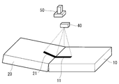
- the flat plate-shaped second base material (second work) 20 is arranged and welded to one edge of the flat plate-shaped first base material (first work) 10. This is a system for aligning the first base material 10 and the second base material 20.
- the robot system 1 includes a robot 2 that grips the second base material 20, a robot control device 30 that controls the operation of the robot 2, a lighting device 40, and a camera 50.
- the first base material 10 is fixed to, for example, a work table (not shown) in a state of being arranged substantially horizontally.
- the robot 2 arranges the gripped second base material 20 substantially horizontally in the vicinity of one edge of the first base material 10.
- the lighting device 40 is arranged above the first base material 10 and irradiates a slit-shaped laser beam.
- the slit-shaped laser beam extends in a direction orthogonal to the boundary B between the first base material 10 and the second base material 20 in a state where the second base material 20 is arranged adjacent to the first base material 10.
- the light is irradiated along a plane that is inclined at a predetermined angle with respect to the surfaces of the first base material 10 and the second base material 20.
- the laser beam is emitted from the first base material 10 and the second base material 20 along a plane that is inclined at an angle smaller than 90 ° with respect to the surfaces of the first base material 10 and the second base material 20.
- the surface is irradiated.
- a first line image 11 extending in a direction orthogonal to the boundary B is formed on the surface of the first base material 10
- a second line image 11 extending in a direction orthogonal to the boundary B is formed on the surface of the second base material 20.
- the line image 21 is formed.
- the camera 50 is also arranged above the first base material 10. Further, the camera 50 arranges the first line image 11 and the second line image 21 formed on both sides of the boundary B within the angle of view, and both the first line image 11 and the second line image 21 are displayed. Acquire a two-dimensional image including.
- the robot control device 30 processes the two-dimensional image acquired by the camera 50 and causes the robot 2 to perform a correction operation. Specifically, the robot control device 30 measures the deviation amount and the deviation direction between the first line image 11 and the second line image 21 in the two-dimensional image, and multiplies the measured deviation amount by a predetermined constant. Calculate the correction amount. Then, the robot control device 30 controls the robot 2 so as to move the second base material 20 to the side opposite to the measured deviation direction by the calculated correction amount.
- the deviation direction between the first line image 11 and the second line image 21 in the two-dimensional image depends on which direction the second line image 21 is deviated from the first line image 11 in the two-dimensional image. Be measured.
- FIG. 2 is an example of a two-dimensional image when the lighting device 40 is arranged at the position of reference numeral 40. In this two-dimensional image, when the second line image 21 on the left side is arranged on the upper side with respect to the first line image 11 on the right side, the second base material 20 is relative to the first base material 10. It can be seen that it is shifted upward.
- the amount of deviation between the first line image 11 and the second line image 21 in the two-dimensional image is measured by the number of pixels between the first line image 11 and the second line image 21 in the two-dimensional image. ..
- the constant to be multiplied by the number of pixels for calculating the correction amount is assumed to be the conversion coefficient multiplied by a predetermined decimal number.
- the operation of the robot system 1 according to the present embodiment configured in this way will be described below.
- the lighting device 40 causes the second base material 20 to be arranged at a position adjacent to one edge.
- a slit-shaped laser beam is irradiated.
- the laser beam emitted from the lighting device 40 forms the first line image 11 and the second line image 21 extending in the direction orthogonal to the boundary B on the surfaces of the first base material 10 and the second base material 20. do. Since the laser beam is inclined at an angle smaller than 90 ° with respect to the surfaces of the first base material 10 and the second base material 20, the first base material 10 and the second base material 20 are in the plate thickness direction. When the image is deviated from the above, the first line image 11 and the second line image 21 are formed so as to be deviated from each other in the direction along the boundary B.
- the two-dimensional image shown in FIG. 2 is acquired and sent to the robot control device 30.
- the two-dimensional image sent from the camera 50 is processed by the robot control device 30.
- the number of pixels between the first line image 11 and the second line image 21 in the two-dimensional image is measured. Then, the measured number of pixels is multiplied by a constant obtained by multiplying a positive decimal number by a conversion coefficient of a unit pixel and an actual deviation amount in the first base material 10 and the second base material 20. The correction amount corresponding to the number of pixels is calculated.
- the offset direction of the second line image 21 with respect to the first line image 11 in the two-dimensional image is set as the deviation direction of which direction the second base material 20 is displaced with respect to the first base material 10. Detected.
- the robot control device 30 determines the direction opposite to the detected deviation direction between the first base material 10 and the second base material 20 as the correction direction.
- the robot control device 30 operates the robot 2 in the determined correction direction by the calculated correction amount.
- the value of the conversion coefficient to be multiplied by the number of pixels is not accurate or there is an error in the amount of movement of the robot 2 with respect to the control command, it is calculated by multiplying by a positive decimal number.
- the correction amount can be made smaller than the actual deviation amount. As a result, the amount of deviation between the first base material 10 and the second base material 20 is corrected without the surface of the second base material 20 passing through the surface of the first base material 10.
- the robot control device 30 again detects the amount of deviation between the first base material 10 and the second base material 20 after the correction, and compares it with a predetermined threshold value stored in advance. As a result, when the amount of deviation between the detected corrected first base material 10 and the second base material 20 is larger than the threshold value, the robot control device 30 detects the corrected first base material 10 and the second base material 20. The robot 2 is operated again based on the amount of deviation from the base material 20 and the direction of deviation. As a result, the amount of deviation between the first base material 10 and the second base material 20 is further reduced as compared with that after the previous correction.
- the correction operation is repeated until the amount of deviation between the first line image 11 and the second line image 21 becomes smaller than the predetermined threshold value, so that the first base material 10 and the second base material 20 are combined.
- the amount of deviation is asymptotically corrected.
- the correction direction is not reversed and is limited to the same direction. Therefore, the step between the first base material 10 and the second base material 20 can be accurately corrected and the correction can be performed.
- the control method can also be simplified.
- the relative positions of the first base material 10 and the second base material 20 can be corrected to the optimum state for butt welding, and good welding is performed. can do.
- the robot control device 30 calculates the correction amount of the robot 2 based on the amount of deviation between the first line image 11 and the second line image 21 in the two-dimensional image. Instead, the robot control device 30 corrects the robot 2 based on the three-dimensional coordinate information in the real space corresponding to the amount of deviation between the first line image 11 and the second line image 21 in the two-dimensional image. May be calculated.
- the camera 50 needs to be calibrated in advance.
- an arbitrary position on the two-dimensional image can be obtained as a three-dimensional line of sight.
- the positional relationship between the slit light emitted by the camera 50 and the lighting device 40 needs to be calibrated in advance.
- the slit light emitted by the illuminating device 40 can be defined as a flat surface.
- the positional relationship between the plane and the camera 50 may be measured in advance and stored in the calibration information.
- the first line image 11 and the second line image are obtained by taking the intersection of the line of sight to an arbitrary point on the first line image 11 and the second line image 21 detected on the two-dimensional image and the plane of the slit light. It is possible to obtain three-dimensional position information of any one point on 21. As a result, a three-dimensional line image on the first line image 11 and the second line image 21 can be obtained.
- the robot control device 30 actually sets the deviation amount and the deviation direction between the first line image 11 and the second line image 21 at the boundary B between the first base material 10 and the second base material 20 in the two-dimensional image. It can be converted into a three-dimensional deviation amount and deviation direction in space. Then, the robot control device 30 operates the robot 2 by a correction amount calculated based on the converted three-dimensional deviation (deviation amount and deviation direction). As a result, the deviation between the first base material 10 and the second base material 20 can be corrected more accurately.
- the robot control device 30 has the surface of the first base material 10 and the second base material 10 based on the deviation amount and the deviation direction between the first line image 11 and the second line image 21 in the two-dimensional image.
- the amount of deviation of the base material 20 from the surface in the plate thickness direction was corrected.
- the inclination between the surface of the first base material 10 and the surface of the second base material 20 may be corrected based on the inclination of the second line image 21 with respect to the first line image 11.
- the surface of the second base material 20 when the surface of the second base material 20 is inclined with respect to the surface of the first base material 10, the surface of the first base material 10 and the first base material 20 are arranged.
- the second line image 21 is also formed so as to be inclined with respect to the first line image 11 in accordance with the inclination of the base material 20 with respect to the surface.
- the robot control device 30 determines the angle formed by the first line image 11 and the second line image 21 and the second mother with respect to the surface of the first base material 10 based on the irradiation angle of the laser beam and the position information of the camera 50 in advance. The inclination direction and the inclination angle of the surface of the material 20 are associated with each other. Then, the robot control device 30 operates the robot 2 based on the angle formed by the first line image 11 and the second line image 21, so that the surface of the first base material 10 and the surface of the second base material 20 are formed. The inclination of can be corrected.
- the tool tip point of the robot 2 is arranged on the edge of the second base material 20 adjacent to the boundary B, and the second base material 20 is corrected. It is preferable that the second base material 20 is rotated around a coordinate axis extending along the edge of the second base material. As a result, the inclination of the second line image 21 can be made parallel to the first line image 11 without moving the tip position of the second line image 21 close to the boundary B. Then, by performing the correction to match the first line image 11 and the second line image 21 described above after this, the first base material 10 and the second base material 20 can be accurately aligned, which is more appropriate. Welding can be carried out.
- the first base material 10 and the second base material 20 are illustrated as a flat base material, but the present invention is not limited to this, and a base material having any shape may be used.
- the amount of deviation between the first line image 11 and the second line image 21 in the two-dimensional image is obtained by the number of pixels, and is corrected by multiplying the conversion coefficient by a constant obtained by multiplying the conversion coefficient by a positive decimal number.
- a constant obtained by multiplying the conversion coefficient by a coefficient of 1 or more may be used. In this case, the correction operation by the robot 2 becomes oscillating, but there are cases where positioning can be performed more quickly.
- the present embodiment exemplifies a robot system in which the first base material 10 and the second base material 20 are butt-welded, but the present invention is not limited to this, and it is necessary to align the steps on the surfaces of adjacent workpieces. If there is, it may be a robot system that performs any work. Twice
- Robot system 2 Robot 10 1st base material (1st work) 11 1st line image 20 2nd base material (2nd work) 21 Second line image 30 Robot control device 40 Lighting device 50 Camera B Boundary
Landscapes
- Engineering & Computer Science (AREA)
- Robotics (AREA)
- Mechanical Engineering (AREA)
- Manipulator (AREA)
Priority Applications (4)
| Application Number | Priority Date | Filing Date | Title |
|---|---|---|---|
| US17/913,321 US12208529B2 (en) | 2020-04-28 | 2021-04-23 | Robot system |
| CN202180028255.7A CN115397632B (zh) | 2020-04-28 | 2021-04-23 | 机器人系统 |
| DE112021001050.6T DE112021001050B4 (de) | 2020-04-28 | 2021-04-23 | Robotersystem |
| JP2023536328A JP7464799B2 (ja) | 2020-04-28 | 2021-04-23 | ロボットシステム |
Applications Claiming Priority (2)
| Application Number | Priority Date | Filing Date | Title |
|---|---|---|---|
| JP2020079172A JP2022028096A (ja) | 2020-04-28 | 2020-04-28 | ロボットシステム |
| JP2020-079172 | 2020-04-28 |
Publications (1)
| Publication Number | Publication Date |
|---|---|
| WO2021220949A1 true WO2021220949A1 (ja) | 2021-11-04 |
Family
ID=78373555
Family Applications (1)
| Application Number | Title | Priority Date | Filing Date |
|---|---|---|---|
| PCT/JP2021/016401 Ceased WO2021220949A1 (ja) | 2020-04-28 | 2021-04-23 | ロボットシステム |
Country Status (5)
| Country | Link |
|---|---|
| US (1) | US12208529B2 (https=) |
| JP (2) | JP2022028096A (https=) |
| CN (1) | CN115397632B (https=) |
| DE (1) | DE112021001050B4 (https=) |
| WO (1) | WO2021220949A1 (https=) |
Citations (3)
| Publication number | Priority date | Publication date | Assignee | Title |
|---|---|---|---|---|
| JPH07117372B2 (ja) * | 1988-01-14 | 1995-12-18 | 松下電器産業株式会社 | 溶接線検出装置 |
| JP2005334957A (ja) * | 2004-05-28 | 2005-12-08 | Ishikawajima Harima Heavy Ind Co Ltd | 溶接部可視化装置 |
| JP2008155285A (ja) * | 1997-02-25 | 2008-07-10 | Sanyo Mach Works Ltd | 溶接状態の検査方法 |
Family Cites Families (12)
| Publication number | Priority date | Publication date | Assignee | Title |
|---|---|---|---|---|
| JPS61132274A (ja) | 1984-12-03 | 1986-06-19 | Ishikawajima Harima Heavy Ind Co Ltd | 多層盛自動溶接装置 |
| JPH0630814B2 (ja) | 1989-10-23 | 1994-04-27 | 松下電工株式会社 | 溶接位置の決定方法および溶接方法 |
| JP3282745B2 (ja) * | 1993-03-16 | 2002-05-20 | 川崎製鉄株式会社 | 2次元距離計を用いた板幅・蛇行測定装置 |
| JP2004087785A (ja) * | 2002-08-27 | 2004-03-18 | Dt Circuit Technology Co Ltd | プリント配線板の製造方法、プリント配線板の製造装置 |
| DE102010041720A1 (de) | 2010-09-30 | 2012-04-05 | Robert Bosch Gmbh | Schweißverfahren, Schweißvorrichtung und Verbundteil |
| KR101400609B1 (ko) * | 2012-07-30 | 2014-05-27 | 현대제철 주식회사 | 라인 스캔 카메라 보정 장치 및 방법 |
| CN203712189U (zh) * | 2014-02-17 | 2014-07-16 | 华南理工大学 | 基于机器视觉的焊接轨迹校正专用测试装置 |
| CN109694946B (zh) | 2017-10-24 | 2020-06-23 | 宝山钢铁股份有限公司 | 快速加热冷轧带钢的装置与方法 |
| US20230146947A1 (en) * | 2017-10-30 | 2023-05-11 | Cilag Gmbh International | Method of hub communication with surgical instrument systems |
| CN109945839B (zh) * | 2017-12-21 | 2021-04-13 | 沈阳新松机器人自动化股份有限公司 | 一种对接工件的姿态测量方法 |
| US11424027B2 (en) * | 2017-12-28 | 2022-08-23 | Cilag Gmbh International | Method for operating surgical instrument systems |
| US11998193B2 (en) * | 2017-12-28 | 2024-06-04 | Cilag Gmbh International | Method for usage of the shroud as an aspect of sensing or controlling a powered surgical device, and a control algorithm to adjust its default operation |
-
2020
- 2020-04-28 JP JP2020079172A patent/JP2022028096A/ja active Pending
-
2021
- 2021-04-23 DE DE112021001050.6T patent/DE112021001050B4/de active Active
- 2021-04-23 CN CN202180028255.7A patent/CN115397632B/zh active Active
- 2021-04-23 JP JP2023536328A patent/JP7464799B2/ja active Active
- 2021-04-23 WO PCT/JP2021/016401 patent/WO2021220949A1/ja not_active Ceased
- 2021-04-23 US US17/913,321 patent/US12208529B2/en active Active
Patent Citations (3)
| Publication number | Priority date | Publication date | Assignee | Title |
|---|---|---|---|---|
| JPH07117372B2 (ja) * | 1988-01-14 | 1995-12-18 | 松下電器産業株式会社 | 溶接線検出装置 |
| JP2008155285A (ja) * | 1997-02-25 | 2008-07-10 | Sanyo Mach Works Ltd | 溶接状態の検査方法 |
| JP2005334957A (ja) * | 2004-05-28 | 2005-12-08 | Ishikawajima Harima Heavy Ind Co Ltd | 溶接部可視化装置 |
Also Published As
| Publication number | Publication date |
|---|---|
| JPWO2021220949A1 (https=) | 2021-11-04 |
| JP7464799B2 (ja) | 2024-04-09 |
| US20230129918A1 (en) | 2023-04-27 |
| DE112021001050T5 (de) | 2023-02-02 |
| DE112021001050B4 (de) | 2026-04-16 |
| CN115397632B (zh) | 2025-05-02 |
| CN115397632A (zh) | 2022-11-25 |
| JP2022028096A (ja) | 2022-02-15 |
| US12208529B2 (en) | 2025-01-28 |
Similar Documents
| Publication | Publication Date | Title |
|---|---|---|
| US20230028351A1 (en) | Laser patterning skew correction | |
| CN108406091B (zh) | 激光加工头及具备拍摄装置的激光加工系统 | |
| US11964396B2 (en) | Device and method for acquiring deviation amount of working position of tool | |
| US20170186656A1 (en) | Wafer processing method | |
| JP2012135781A (ja) | レーザ加工ロボットの教示方法及び教示装置 | |
| WO2008010469A1 (en) | Laser processing system and laser processing method | |
| US20230211437A1 (en) | Laser machining system | |
| JP2019063955A (ja) | ロボットシステム、動作制御方法及び動作制御プログラム | |
| JP2019063954A (ja) | ロボットシステム、キャリブレーション方法及びキャリブレーションプログラム | |
| WO2011052093A1 (ja) | 開先の切断装置および切断方法 | |
| JP2022028522A (ja) | 溶接方法 | |
| TWI592239B (zh) | 用於將鐳射對準於工作表面的鐳射裝置和方法 | |
| TWI392551B (zh) | 雷射加工裝置及雷射加工方法 | |
| CN114589316B (zh) | 层叠造形装置及其校正方法 | |
| JP2017020797A (ja) | 鋼板位置検出装置及び切断装置 | |
| JP7464799B2 (ja) | ロボットシステム | |
| WO2020137184A1 (ja) | 自動溶接システム、エレベーターかご室部品の製造方法、および自動溶接方法 | |
| KR20160118175A (ko) | 핵연료집합체용 지지격자의 레이저 용접을 위한 용접치구 | |
| KR20160064310A (ko) | 용접치구 및, 이를 이용한 핵연료집합체용 지지격자의 레이저 용접방법 | |
| JP2019093423A (ja) | ワーク加工装置 | |
| JP2019119034A (ja) | 自動組立装置及びその制御方法 | |
| JP2014007213A (ja) | 部品実装装置及び部品実装方法 | |
| JP2012103099A (ja) | 部品位置計測方法 | |
| JP2007307612A (ja) | 自動溶接方法及び自動溶接装置並びに自動溶接に用いる基準治具 | |
| US20240123606A1 (en) | Teaching point generation device that generates teaching points on basis of output of sensor, and teaching point generation method |
Legal Events
| Date | Code | Title | Description |
|---|---|---|---|
| 121 | Ep: the epo has been informed by wipo that ep was designated in this application |
Ref document number: 21797250 Country of ref document: EP Kind code of ref document: A1 |
|
| ENP | Entry into the national phase |
Ref document number: 2023536328 Country of ref document: JP Kind code of ref document: A |
|
| 122 | Ep: pct application non-entry in european phase |
Ref document number: 21797250 Country of ref document: EP Kind code of ref document: A1 |
|
| WWG | Wipo information: grant in national office |
Ref document number: 202180028255.7 Country of ref document: CN |