WO2021215161A1 - Antenne à guide d'ondes multimode - Google Patents
Antenne à guide d'ondes multimode Download PDFInfo
- Publication number
- WO2021215161A1 WO2021215161A1 PCT/JP2021/011378 JP2021011378W WO2021215161A1 WO 2021215161 A1 WO2021215161 A1 WO 2021215161A1 JP 2021011378 W JP2021011378 W JP 2021011378W WO 2021215161 A1 WO2021215161 A1 WO 2021215161A1
- Authority
- WO
- WIPO (PCT)
- Prior art keywords
- mode
- waveguide
- transmission line
- circular waveguide
- antenna
- Prior art date
Links
Images


Classifications
-
- H—ELECTRICITY
- H01—ELECTRIC ELEMENTS
- H01P—WAVEGUIDES; RESONATORS, LINES, OR OTHER DEVICES OF THE WAVEGUIDE TYPE
- H01P5/00—Coupling devices of the waveguide type
- H01P5/02—Coupling devices of the waveguide type with invariable factor of coupling
-
- H—ELECTRICITY
- H01—ELECTRIC ELEMENTS
- H01Q—ANTENNAS, i.e. RADIO AERIALS
- H01Q13/00—Waveguide horns or mouths; Slot antennas; Leaky-waveguide antennas; Equivalent structures causing radiation along the transmission path of a guided wave
- H01Q13/06—Waveguide mouths
-
- H—ELECTRICITY
- H01—ELECTRIC ELEMENTS
- H01Q—ANTENNAS, i.e. RADIO AERIALS
- H01Q13/00—Waveguide horns or mouths; Slot antennas; Leaky-waveguide antennas; Equivalent structures causing radiation along the transmission path of a guided wave
- H01Q13/08—Radiating ends of two-conductor microwave transmission lines, e.g. of coaxial lines, of microstrip lines
-
- H—ELECTRICITY
- H01—ELECTRIC ELEMENTS
- H01Q—ANTENNAS, i.e. RADIO AERIALS
- H01Q13/00—Waveguide horns or mouths; Slot antennas; Leaky-waveguide antennas; Equivalent structures causing radiation along the transmission path of a guided wave
- H01Q13/10—Resonant slot antennas
- H01Q13/12—Longitudinally slotted cylinder antennas; Equivalent structures
Definitions
- the present invention relates to a multimode waveguide antenna provided in a waveguide that transmits electromagnetic waves in a plurality of transmission modes.
- MIMO multiple-input and multiple-output
- the field of use of MIMO is expanding from the viewpoint that communication capacity can be increased without increasing bandwidth and transmission output.
- MIMO is a technology that improves the transmission speed of the radio section by connecting multiple antennas to the transmitter and receiver of the radio. For example, in 3 ⁇ 3 MIMO, transmission by 3 systems (3 streams) becomes possible, and the communication speed is improved. In order to realize MIMO, it is necessary to provide an independent antenna for each radio. As a result, different propagation channels (3 ⁇ 3 propagation channel matrix) are formed. If three outputs are combined from the radio and output from one antenna, the propagation channel matrix has only eigenvalues, and one stream communication is performed.
- Non-Patent Document 1 As a method of "mode separation" of a waveguide, a method (separator) for separating two modes of an orthogonal rectangular waveguide is described in, for example, Non-Patent Document 1. Such a mode separation method is a general method as used in a bipolar weather radar or the like. Further, Non-Patent Document 2 describes a method in which the input of a rectangular waveguide is divided into two branches having 180-degree phases different from each other. This method is a general method called a polarizer.
- Non-Patent Document 1 is a method of separating two modes of a rectangular waveguide orthogonal to a circular waveguide
- Non-Patent Document 2 is a method of dividing the input of a rectangular waveguide into two branches having 180-degree phases different from each other. Each is a method of separating into a rectangular TE11 mode.
- An object of the present invention is to provide a multi-mode waveguide antenna which is connected to a waveguide which propagates a multi-mode electromagnetic wave, separates signals of each mode and radiates them to the outside of the waveguide.
- the multi-mode waveguide antenna of the present invention is an antenna connected to a circular waveguide that propagates an electromagnetic wave in TE11 mode and an electromagnetic wave in TM01 mode.
- This multi-mode waveguide antenna separates and synthesizes the TE11 mode electromagnetic wave from the circular waveguide and the TE11 mode transmission line and the TM01 mode electromagnetic wave between the circular waveguide.
- the TM01 mode transmission line to be separated and combined, the TE11 mode radiation element coupled to the electromagnetic wave propagating in the TE11 mode transmission line, and the TM01 mode radiation element coupled to the electromagnetic wave propagating in the TM01 mode transmission line. , Equipped with.
- the circular waveguide can be used as a multi-mode waveguide, and the multi-mode electromagnetic wave propagating in this circular waveguide is coupled with an independent radiating element for each mode.
- a multi-mode waveguide antenna which is connected to a waveguide which propagates a multi-mode electromagnetic wave, separates signals of each mode and radiates them to the outside of the waveguide.
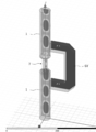
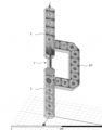
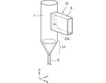
- FIG. 1 is a perspective view of the multimode waveguide antenna 201 according to the first embodiment.
- FIG. 2 is a front view of the multimode waveguide antenna 201.
- FIG. 3 shows the distribution of the electric field strength of the electromagnetic wave in the TM01 mode propagating in the circular waveguide 1, the distribution of the electric field strength of the electromagnetic wave in the TEM mode propagating in the transmission line 7 for the TM01 mode, and the distribution of the electric field strength in the transmission line 6Y for the TE11y mode. It is a figure which shows the electric field strength.
- FIG. 3 shows the distribution of the electric field strength of the electromagnetic wave in the TM01 mode propagating in the circular waveguide 1, the distribution of the electric field strength of the electromagnetic wave in the TEM mode propagating in the transmission line 7 for the TM01 mode, and the distribution of the electric field strength in the transmission line 6Y for the TE11y mode. It is a figure which shows the electric field strength.
- FIG. 4 shows the distribution of the electric field strength of the electromagnetic wave in the TE11y mode propagating in the circular waveguide 1, the distribution of the electric field strength of the electromagnetic wave in the TE11 mode propagating in the transmission line 6Y for the TE11y mode, and the distribution of the electric field strength in the transmission line 7 for the TM01 mode. It is a figure which shows the electric field strength.
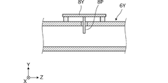
- FIG. 5 is a cross-sectional view showing the configuration of the TM01 mode transmission line 7 and the TM01 mode patch antenna 9.
- FIG. 6 is a front view showing the configuration of the coupling portion between the TE11y mode transmission line 6Y and the circular waveguide 1.
- FIG. 7 is a cross-sectional view showing the configuration of the TE11y mode transmission line 6Y and the TE11y mode patch antenna 8Y.
- FIG. 8 is a perspective view of a multimode waveguide connector connected to the circular waveguide 1.
- 9 (A) is a cross-sectional view of the multi-mode waveguide connector
- FIG. 9 (B) is a front view of the multi-mode waveguide connector.
- FIG. 10 is a diagram showing the distribution of the electromagnetic field in the TEM mode propagating on the coaxial line.
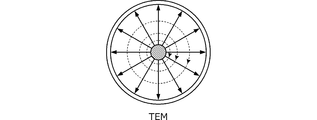
- FIG. 11A is a diagram showing the distribution of the electromagnetic field in the TM01 mode propagating in the circular waveguide 1
- FIG. 11B is a diagram showing the distribution of the electromagnetic field in the TE11 mode propagating in the circular waveguide 1. It is a figure.
- FIG. 12 (A) is a diagram showing the electromagnetic field distribution of the coaxial TM01 mode propagating through the port 10 for the TM01 mode
- FIG. 12 (B) is the electromagnetic field distribution of the coaxial TE11 mode blocked by the port 10 for the TM01 mode. It is a figure which shows.
- FIG. 13 is a partial plan view showing the configuration of the TE11y mode transmission line 6Y according to the second embodiment.
- the outline of the multi-mode waveguide antenna according to the embodiment of the present invention is as follows.
- this multi-mode waveguide antenna is an antenna that propagates multi-mode electromagnetic waves in the waveguide and emits signals of each mode independently from a plurality of radiating elements.
- the TM01 mode, TE11x mode, and TE11y mode signals are independently extracted from the circular waveguide.
- the TM01 mode is converted into the coaxial line mode, and the TE11x mode and the TE11y mode are converted into the rectangular waveguide mode.
- the coaxial line is configured by reducing the diameter of the circular waveguide and loading the inner conductor. As will be shown later, by reducing the diameter, the coaxial TE11x mode and the coaxial TE11y mode are set to the cutoff frequency so that transmission is not possible.
- a rectangular waveguide which is a transmission line for the TE mode that transmits only the TE11x mode and the TE11y mode, is loaded on the circular waveguide. That is, the rectangular waveguide is connected to the circular waveguide via the coupling window, and is configured to straddle the TM01 mode transmission line.
- the plurality of radiating elements are separated from the circular waveguide and loaded on the transmission line for transmitting the signals of TM01 mode, TE11x mode and TE11y mode. This allows each radiating element to radiate only a single mode signal.
- FIG. 1 is a perspective view of the multimode waveguide antenna 201 according to the first embodiment.
- FIG. 2 is a front view of the multimode waveguide antenna 201.
- FIG. 11A is a diagram showing the distribution of the electromagnetic field in the TM01 mode propagating in the circular waveguide 1
- FIG. 11B is a diagram showing the distribution of the electromagnetic field in the TE11 mode propagating in the circular waveguide 1. It is a figure. In these figures, the solid line shows the direction and distribution of the electric field, and the broken line shows the direction and distribution of the magnetic field.
- the multi-mode waveguide antenna 201 is an antenna provided in the circular waveguide 1 that propagates the TM01 mode electromagnetic wave, the TE11x mode electromagnetic wave, and the TE11y mode electromagnetic wave.
- the TE11 mode in which the X direction is the plane of polarization of the electric field is called the TE11x mode
- the TE11 mode in which the Y direction is the plane of polarization of the electric field is called the TE11y mode.
- the multimode waveguide antenna 201 separates the TE11x mode transmission line 6X, which separates and synthesizes the TE11x mode electromagnetic wave from the circular waveguide 1, and the TE11y mode electromagnetic wave from the circular waveguide 1.
- the TE11y mode transmission line 6Y to be combined and the TM01 mode transmission line 7 for separating and synthesizing the TM01 mode electromagnetic wave from the circular waveguide 1.
- the TE11x mode transmission line 6X and the TE11y mode transmission line 6Y are provided at two locations separated in the circumferential direction of the circular waveguide 1.
- the connection position of the TE11x mode transmission line 6X to the circular waveguide 1 faces the Y direction shown in FIG. 1, and the connection position of the TE11y mode transmission line 6Y to the circular waveguide 1 faces the X direction. That is, the TE11x mode transmission line 6X and the TE11y mode transmission line 6Y are arranged in an angular relationship of 90 ° in the circumferential direction of the circular waveguide.
- the TE11x mode transmission line 6X is coupled to the circular waveguide 1 for the TE11x mode propagating the circular waveguide 1
- the TE11y mode transmission line 6Y is for the TE11y mode propagating the circular waveguide 1.
- the multi-mode waveguide antenna 201 includes a TE11x mode patch antenna 8X that couples to a TE11x mode electromagnetic wave that propagates in a TE11x mode transmission path 6X, and a TE11y that couples to a TE11y mode electromagnetic wave that propagates in a TE11y mode transmission path 6Y.
- the mode patch antenna 8Y and the TM01 mode patch antenna 9 coupled to the TM01 mode electromagnetic wave propagating in the TM01 mode transmission path 7 are provided.
- FIG. 2 is a front view in the direction in which the patch antenna 9 is viewed from the front.
- the TM01 mode transmission line 7 is inserted between the two circular waveguides 1 in the axial direction of the circular waveguide 1.
- the TM01 mode transmission line 7 includes a coaxial line.
- the TM01 mode transmission line 7 mutually converts the TM01 mode propagating in the circular waveguide 1 and the TEM mode propagating in the coaxial line.
- the TE11x mode transmission line 6X is composed of a rectangular waveguide having bends that bend at right angles at two points in the middle.
- the TE11y mode transmission line 6Y is also composed of a rectangular waveguide having bends that bend at right angles at two points along the way. As will be shown later, these bends are H bends.
- the TE11x mode transmission line 6X mutually converts the TE11x mode propagating in the circular waveguide 1 and the TE11 mode propagating in the rectangular waveguide 1.
- the TE11y mode transmission line 6Y mutually converts the TE11y mode propagating in the circular waveguide 1 and the TE11 mode propagating in the rectangular waveguide 1.
- the TM01 mode patch antenna 9 is a radiating element that couples to the TEM mode electromagnetic wave propagating in the TM01 mode transmission line 7.
- the TE11x mode patch antenna 8X is a TE11x mode radiating element that couples to an electromagnetic wave of the TE11 mode propagating in the TE11x mode transmission line 6X.
- the TE11y mode patch antenna 8Y is a TE11y mode radiating element that couples to an electromagnetic wave of the TE11 mode propagating in the TE11y mode transmission line 6Y.
- FIG. 3 shows the distribution of the electric field strength of the electromagnetic wave in the TM01 mode propagating in the circular waveguide 1, the distribution of the electric field strength of the electromagnetic wave in the TEM mode propagating in the transmission line 7 for the TM01 mode, and the distribution of the electric field strength in the transmission line 6Y for the TE11y mode. It is a figure which shows the electric field strength.
- the electromagnetic wave of the TM01 mode propagates in the circular waveguide 1, and propagates as the electromagnetic wave of the TEM mode in the transmission line 7 for the TM01 mode.
- the electromagnetic wave of TM01 mode does not propagate in the transmission line 6Y for TE11y mode.
- the TE11x mode transmission line 6X is not shown in FIG. 3, similarly, the TM01 mode electromagnetic wave does not propagate to the TE11x mode transmission line 6X.
- FIG. 4 shows the distribution of the electric field strength of the electromagnetic wave in the TE11y mode propagating in the circular waveguide 1, the distribution of the electric field strength of the electromagnetic wave in the TE11 mode propagating in the transmission line 6Y for the TE11y mode, and the distribution of the electric field strength in the transmission line 7 for the TM01 mode. It is a figure which shows the electric field strength. As will be shown later, the TE11 mode electromagnetic wave propagates in the TE11y mode transmission line 6Y, and the TEM mode electromagnetic wave does not propagate in the TM01 mode transmission line 7.
- FIG. 5 is a cross-sectional view showing the configuration of the TM01 mode transmission line 7 and the TM01 mode patch antenna 9.
- FIG. 10 is a diagram showing the distribution of the electromagnetic field in the TEM mode propagating on the coaxial line, which will be described later.
- the inner diameter of the outer conductor 12 of this coaxial line is smaller than the inner diameter of the circular waveguide 1.
- the coaxial line has a cutoff frequency characteristic that blocks the TE11x mode electromagnetic wave and the TE11y mode electromagnetic wave propagating through the circular waveguide 1 (that is, blocks the TE11 mode electromagnetic wave). That is, the TM01 mode transmission line 7 blocks the electromagnetic waves of the TE11x mode and the TE11y mode, and acts as a filter through which the electromagnetic waves of the TM01 mode pass.
- a TM01 mode patch antenna 9 is provided on the outer surface of the outer conductor 12 of the TM01 mode transmission line 7.
- the patch antenna 9 is fixed to the outer surface of the outer conductor 12 of the TM01 mode transmission line 7 via an insulator.
- a probe 9P is provided inside the transmission line 7 for TM01 mode.
- One end of the probe 9P is connected to the inner wall surface of the outer conductor 12, and the other end is connected to a predetermined feeding point of the patch antenna 9.
- the probe 9P is arranged so that its loop surface is orthogonal to the circumferential direction of the inner conductor 13. That is, the probe 9P acts as a magnetic field probe that couples with a TEM mode magnetic field propagating on the coaxial line.
- FIG. 6 is a front view showing the configuration of the coupling portion between the TE11y mode transmission line 6Y and the circular waveguide 1 shown in FIG.
- FIG. 6 is a front view in a direction in which the mounting surface of the TE11y mode transmission line 6Y is viewed from the front with the TE11y mode transmission line 6Y shown in FIG. 1 removed from the circular waveguide 1.
- the TE11y mode transmission line (6Y in FIGS. 1 and 2) has a coupling window 1SL that opens a part of the side surface of the circular waveguide 1.
- the coupling window 1SL is a slot-shaped opening extending in the axial direction (Z direction) of the circular waveguide 1, and is an electric field coupling window. That is, the electric field of the TE11y mode electromagnetic wave propagating through the circular waveguide 1 is directed in the Y direction.
- the coupling window 1SL has a shape extending in the propagation direction of the electromagnetic wave in the TE11y mode in the circular waveguide 1.
- FIG. 7 is a cross-sectional view showing the configuration of the TE11y mode transmission line 6Y and the TE11y mode patch antenna 8Y.
- a pin 8P is formed at a predetermined feeding point of the patch antenna 8Y.
- the pins 8P are arranged so as to face the electric field direction (Y direction) of the electromagnetic wave of the TE11 mode propagating in the transmission line 6Y for the TE11y mode. Therefore, the pin 8P acts as an electric field probe that couples with the electric field of the TE11 mode propagating in the transmission line 6Y for the TE11y mode.
- the patch antenna 8Y is fed by the pin 8P and radiates electromagnetic waves to the outside. That is, the TE11y mode patch antenna 8Y radiates the TE11y mode signal propagating through the circular waveguide 1.
- the configuration of the coupling portion between the other TE11x mode transmission line 6X and the circular waveguide 1 is the same as the example shown in FIG. That is, a coupling window is provided on a part of the side surface of the circular waveguide 1 to which the TE11x mode transmission line 6X is connected. As a result, the TE11x mode electromagnetic wave propagating through the circular waveguide 1 and the TE11 mode electromagnetic wave propagating through the TE11x mode transmission line 6X are coupled through the coupling window.
- a TE11x mode patch antenna 8X (see FIG. 1) is provided on the outer surface of the TE11x mode transmission line 6X, and a pin is formed at a predetermined feeding point of the patch antenna 8X.
- the probes are arranged so as to face the electric field direction (X direction) of the TE11 mode electromagnetic wave propagating in the TE11x mode transmission line 6X. Therefore, the pin acts as an electric field probe that couples with the electric field of the TE11 mode propagating in the transmission line 6X for the TE11x mode.
- the patch antenna 8X is fed by the above probe and radiates electromagnetic waves to the outside. That is, the TE11x mode patch antenna 8X radiates the TE11x mode signal propagating through the circular waveguide 1.
- each electromagnetic wave of TM01 mode, TE11x mode and TE11y mode independently propagates in the circular waveguide 1.
- the TM01 mode patch antenna 9 provided in the TM01 mode transmission line 7 radiates a TM01 mode signal propagating through the circular waveguide 1.
- Mode conversion between the circular waveguide 1 and the TE11x mode transmission line 6X is performed between the circular waveguide 1 TE11x mode and the square waveguide 6 TE11 mode, and the TE11x mode transmission line 6X is performed. Acts as a bypass transmission line for TE11x mode signals.
- the mode conversion between the TE11y mode of the circular waveguide 1 and the TE11 mode of the square waveguide 6 is performed, and the mode is converted for the TE11y mode.
- the transmission line 6Y acts as a bypass transmission line for the TE11y mode signal.
- the TE11x mode patch antenna 8X provided in the TE11x mode transmission line 6X radiates the TE11x mode signal propagating through the circular waveguide 1.
- the TE11y mode patch antenna 8Y provided in the TE11y mode transmission line 6Y radiates the TE11y mode signal propagating through the circular waveguide 1.
- the multi-mode waveguide antenna 201 is inserted between the TM01 mode transmission line 7, the TE11x mode transmission line 6X, and the TE11y mode transmission line 6Y between the circular waveguide 1 and the circular waveguide 1. Therefore, the multi-mode waveguide antenna 201 can be inserted into a plurality of necessary locations of the long circular waveguide 1.
- a circular waveguide 1 made of a single pipe can be installed in a vertical direction in a building under construction, and a multimode waveguide antenna 201 can be installed on each floor. This facilitates MIMO communication with equipment and personnel on each floor.
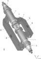
- FIG. 8 is a perspective view of a multimode waveguide connector connected to the circular waveguide 1.
- This multi-mode waveguide connector is a connector provided on the circular waveguide 1 that propagates the electromagnetic waves of the TE11 mode and the electromagnetic waves of the TM01 mode.
- the TM01 mode port 10 for inputting / outputting the TM01 mode electromagnetic wave to the end of the circular waveguide 1
- the TE11y mode port 11Y for inputting / outputting the TE11y mode electromagnetic wave to the side of the circular waveguide 1. It shows that.
- a coaxial cable 5 is connected to the TM01 mode port 10.
- the TE11y mode port 11Y includes a rectangular waveguide 6. In FIG. 8, a part of the rectangular waveguide 6 is shown.
- FIG. 9 (A) is a cross-sectional view of the multi-mode waveguide connector
- FIG. 9 (B) is a front view of the multi-mode waveguide connector
- 9 (A) is a cross-sectional view taken along the line YY in FIG. 9 (B).
- the TM01 mode port 10 is composed of an inner conductor 3 and an outer conductor 2.
- the TM01 mode port 10 includes a coaxial connector 10C for connecting the coaxial cable 5.
- the TM01 mode port 10 is a tapered coaxial line 4 in which the inner conductor 3 extends in a tapered shape toward the inner wall surface of the circular waveguide 1 from the coaxial connector 10C to the circular waveguide 1.
- the tapered coaxial line 4 has a cutoff frequency characteristic of propagating electromagnetic waves in coaxial TM01 mode and blocking electromagnetic waves in coaxial TE11 mode.
- the TE11y mode port 11Y has a coupling window 1SL that opens a part of the side surface of the circular waveguide 1.
- the coupling window 1SL is a slot-shaped opening extending in the axial direction (Z direction) of the circular waveguide 1, and is an electric field coupling window. That is, the electromagnetic wave of the TE11y mode in which the electric field is directed in the Y direction propagates through the circular waveguide 1.
- FIG. 12 (A) is a diagram showing the electromagnetic field distribution of the coaxial TM01 mode propagating through the port 10 for the TM01 mode
- FIG. 12 (B) is the electromagnetic field distribution of the coaxial TE11 mode blocked by the port 10 for the TM01 mode. It is a figure which shows. In these figures, the solid line shows the direction and distribution of the electric field, and the broken line shows the direction and distribution of the magnetic field.
- the electromagnetic wave of the TEM mode propagates to the coaxial cable 5 connected to the coaxial connector 10C shown in FIG. 9A, and the electromagnetic wave of the coaxial TM01 mode propagates to the port 10 for the TM01 mode.
- the electromagnetic wave of the coaxial TE11 mode is blocked at the port 10 for the TM01 mode.
- the tapered coaxial line 4 is configured so as to have such a cutoff frequency characteristic. That is, the TEM mode signal propagating through the coaxial cable 5 is converted into the coaxial TM01 mode at the TM01 mode port 10, and the TM01 mode is excited to the circular waveguide 1.
- the coaxial TE11 mode has a cutoff frequency, so that the TE11 mode signal is not output from the TM01 mode port 10.
- the tapered coaxial line 4 of the TM01 mode port 10 gradually matches the characteristic impedance from the coaxial line to the waveguide, while the TM01 mode port 10 is ideally a short-circuit plate when viewed from the TE11y mode port 11Y.
- the diameter of the wide end (open end) of the tapered coaxial line 4 and the diameter of the circular waveguide 1 are set to extremely close values. Since there is a gap between the inner conductor 3 and the outer conductor 2 of the tapered coaxial line 4, it is possible to excite the circular waveguide 1 in the TM01 mode.
- the tapered coaxial line 4 does not become a complete short-circuit plate (electrical wall) because the cutoff frequency of the TE11 mode decreases at the extended end WE of the inner conductor 3 and the outer conductor 2. A part of the cable does not reflect and enters the inside of the tapered coaxial line 4 as the coaxial TE11 mode. However, since the coaxial TE11 mode is cut off at a place where the inner conductor 3 and the outer conductor 2 have a small diameter to some extent, the coaxial TE11 The electromagnetic wave of the mode is reflected in one direction of the circular waveguide. If the design is made in consideration of the penetration depth, desired characteristics can be obtained.
- the electromagnetic wave in the coaxial TE11 mode propagating through the circular waveguide 1 is ideally reflected by the end WE having a large diameter of the inner conductor 3 of the tapered coaxial line 4, but in reality, this diameter is large. It is reflected by the reflecting portion RE, which is a position where the diameter is slightly smaller than that of the end portion WE in the direction of the end portion NE.
- the TM01 mode current propagating through the circular waveguide 1 flows in the axial direction (Z direction) through the tube wall of the circular waveguide 1, but the coupling window 1SL extends in the axial direction of the circular waveguide 1. Since it is short in the circumferential direction, the coupling window 1SL does not block the current in TM01 mode. That is, the coupling window 1SL does not hinder the propagation of electromagnetic waves in the TM01 mode.
- the center of the TE11y mode port 11Y is formed at a position separated by ⁇ g / 2 from the reflection portion RE of the TM01 mode port 10.
- the electromagnetic wave of TE11y mode incident from the port 11Y for TE11y mode propagates in the + Z direction and the ⁇ Z direction, but the electromagnetic wave of TE11 mode reflected by the reflection unit RE of the port 10 for TM01 mode and the electromagnetic wave of TE11 mode propagating in the + Z direction. It is superposed in phase with the electromagnetic waves. That is, the attenuation and phase shift of the electromagnetic wave in the TE11 mode are avoided.
- the signal input from the TM01 mode port 10 propagates through the circular waveguide 1 as an electromagnetic wave in the TM01 mode, and the signal input from the TE11y mode port 11Y transmits the circular waveguide 1 through the TE11y. Propagates as a mode electromagnetic wave, ensuring isolation between both ports.
- FIGS. 8, 9 (A) and 9 (B) only the port 11Y for the TE11y mode is shown for the TE11 mode, but the same applies to the TE11x mode, which is biased from the port 11Y for the TE11y mode.
- a port for TE11x mode is provided at a position where the wave planes are orthogonal to each other.
- only one set of the multimode waveguide connectors shown above may be provided, and a non-reflective terminator may be provided at the other end of the circular waveguide 1.
- the TM01 mode signal propagating in the circular waveguide 1 connected to the circular waveguide 1 propagating the multimode electromagnetic wave is radiated from the TM01 mode patch antenna 9, and the circular waveguide is emitted.
- the TE11x mode signal propagating through the tube 1 is radiated from the TE11x mode patch antenna 8X, and the TE11y mode signal propagating through the circular waveguide 1 is radiated from the TE11y mode patch antenna 8Y. Is obtained.
- each of the above patch antennas can be applied not only to transmission but also to reception.
- Second Embodiment In the second embodiment, other configurations of the radiating element for each mode will be illustrated.
- FIG. 13 is a partial plan view showing the configuration of the TE11y mode transmission line 6Y according to the second embodiment.
- the TE11y mode transmission line 6Y is provided with a plurality of slot antennas SL in place of the TE11y mode patch antenna 8Y.
- a slot-shaped opening is formed in a plane (E plane) orthogonal to the electric field direction of the square waveguide 6 or a plane (H plane) parallel to the electric field direction.
- the slot antenna SL may be formed on either the E plane or the H plane depending on the orientation of the plane of polarization.
- a slot antenna may be provided instead of the patch antenna 8X.
- the TE11x mode signal propagating through the circular waveguide 1 is radiated from the slot antenna of the TE11x mode transmission line 6X.
- the TM01 mode transmission line 7 may be provided with a slot antenna instead of the patch antenna 9.
- the TM01 mode signal propagating through the circular waveguide 1 is radiated from the slot antenna of the TM01 mode transmission line 7.
- the "circular waveguide” in the present invention is a waveguide in which an electromagnetic field in the circular waveguide mode is generated in the tube, and is not necessarily a perfect circle.
- the cross section on the plane orthogonal to the axis may be polygonal.
- the multi-mode waveguide antenna 201 including the TE11x mode transmission line 6X and the TE11y mode transmission line 6Y is illustrated, but the circular waveguide 1 has three or more TE11 modes.
- the electromagnetic wave may be propagated.
- three TE11 modes are used, three TE11 mode transmission lines may be provided around the axis (Z direction) of the circular waveguide 1 in a relationship of 120 degrees.
- n or more transmission lines for TE11 mode are provided, each input angle is set to 360 ° / n. In these cases, isolation between TE11 modes that are not orthogonal to each other is reduced, but can be used to the extent possible in signal processing.
- the multimode waveguide antenna 201 including the TE11x mode transmission line 6X and the TE11y mode transmission line 6Y is illustrated, but only a single TE11 mode is used. You may.
- NE End with small diameter of inner conductor WE ... End with large diameter of inner conductor RE ... Reflector SL ... Slot antenna 1 ... Circular waveguide 1SL ... Coupling window 2 ... Outer conductor 3 ... Inner conductor 4 ... Tapered coaxial Line 5 ... Coaxial cable 6 ... Square waveguide 6X ... TE11x mode transmission line 6Y ... TE11y mode transmission line 7 ... TM01 mode transmission line 8P ... Pin 8X ... TE11x mode patch antenna 8Y ... TE11y mode patch antenna 9 ... TM01 mode patch antenna 9P ... Probe 10 ... TM01 mode port 10C ... Coaxial connector 11Y ... TE11y mode port 12 ... Outer conductor 13 ... Inner conductor 13P ... Pin 14 ... Insulator 201 ... Multimode waveguide antenna
Landscapes
- Waveguide Aerials (AREA)
Abstract
Le problème à résoudre par la présente invention est de construire une antenne à guide d'ondes multimode connectée à un guide d'ondes pour propager des ondes électromagnétiques multimode, l'antenne à guide d'ondes multimode séparant des signaux de divers modes et émettant les signaux respectifs vers l'extérieur du guide d'ondes. La solution selon l'invention porte sur une antenne à guide d'ondes multimode 201 qui est connectée à un guide d'ondes circulaire 1 pour propager des ondes électromagnétiques d'un mode TE11 et d'ondes électromagnétiques d'un mode TM01. L'antenne à guide d'ondes multimode 201 comprend : des chemins de transfert de mode TE11 6X, 6Y pour effectuer la séparation et la composition d'ondes électromagnétiques de mode TE11 entre les chemins de transfert de mode TE11 6X, 6Y et le guide d'ondes circulaire 1 ; un chemin de transfert de mode TM01 7 pour effectuer la séparation et la composition d'ondes électromagnétiques de mode TM01 entre le chemin de transfert de mode TM01 7 et le guide d'ondes circulaire 1 ; des antennes à plaque de mode TE11 8X, 8Y pour le couplage avec les ondes électromagnétiques se propageant dans les chemins de transfert de mode TE11 6X, 6Y ; et une antenne à plaque de mode TM01 9 pour le couplage avec les ondes électromagnétiques se propageant dans le chemin de transfert de mode TM01 7.
Priority Applications (1)
| Application Number | Priority Date | Filing Date | Title |
|---|---|---|---|
| JP2022516896A JPWO2021215161A1 (fr) | 2020-04-20 | 2021-03-19 |
Applications Claiming Priority (2)
| Application Number | Priority Date | Filing Date | Title |
|---|---|---|---|
| JP2020-074836 | 2020-04-20 | ||
| JP2020074836 | 2020-04-20 |
Publications (1)
| Publication Number | Publication Date |
|---|---|
| WO2021215161A1 true WO2021215161A1 (fr) | 2021-10-28 |
Family
ID=78269398
Family Applications (1)
| Application Number | Title | Priority Date | Filing Date |
|---|---|---|---|
| PCT/JP2021/011378 WO2021215161A1 (fr) | 2020-04-20 | 2021-03-19 | Antenne à guide d'ondes multimode |
Country Status (2)
| Country | Link |
|---|---|
| JP (1) | JPWO2021215161A1 (fr) |
| WO (1) | WO2021215161A1 (fr) |
Citations (1)
| Publication number | Priority date | Publication date | Assignee | Title |
|---|---|---|---|---|
| JPS56104201U (fr) * | 1980-12-17 | 1981-08-14 |
-
2021
- 2021-03-19 JP JP2022516896A patent/JPWO2021215161A1/ja active Pending
- 2021-03-19 WO PCT/JP2021/011378 patent/WO2021215161A1/fr active Application Filing
Patent Citations (1)
| Publication number | Priority date | Publication date | Assignee | Title |
|---|---|---|---|---|
| JPS56104201U (fr) * | 1980-12-17 | 1981-08-14 |
Non-Patent Citations (1)
| Title |
|---|
| GIERULL CHRISTOPH H, LUKOWSKI TOM I: "Analysis of the Multimode Feedhorn Concept for Multi- channel SAR-GMTI", EUROPEAN CONFERENCE ON SYNTHETIC APERTURE RADAR, 1 June 2011 (2011-06-01), pages 649 - 652, XP055866677 * |
Also Published As
| Publication number | Publication date |
|---|---|
| JPWO2021215161A1 (fr) | 2021-10-28 |
Similar Documents
| Publication | Publication Date | Title |
|---|---|---|
| US8878629B2 (en) | Diplexer for a reflector antenna | |
| EP3635811B1 (fr) | Polariseur circulaire d'hyperfréquence | |
| WO2012172565A1 (fr) | Coupleur hyperfréquence basé sur une jonction à tourniquet de guide d'onde à large bande et système d'alimentation à poursuite monopulse | |
| JPS6115601B2 (fr) | ||
| US6577207B2 (en) | Dual-band electromagnetic coupler | |
| EP3404766B1 (fr) | Circuit de guides d'ondes | |
| EP0458226B1 (fr) | Transducteur orthomode entre un guide d'ondes circulaire et un câble coaxial | |
| WO2022085653A1 (fr) | Dispositif d'antenne et dispositif radar | |
| JP5600359B2 (ja) | 二帯域マイクロ波放射エレメント | |
| US6816026B2 (en) | Orthogonal polarization and frequency selectable waveguide using rotatable waveguide sections | |
| JPH0441521B2 (fr) | ||
| EP2600465B1 (fr) | Transducteur orthomode | |
| WO2021215161A1 (fr) | Antenne à guide d'ondes multimode | |
| US3380057A (en) | Dual band ridged feed horn | |
| CN109473774B (zh) | 新型双极化天线 | |
| WO2021215160A1 (fr) | Connecteur de guide d'ondes multimode et guide d'ondes | |
| KR101491723B1 (ko) | 커플러를 이용한 이중 대역 피드혼 | |
| KR20180128743A (ko) | 광대역 모노펄스 위상비교기 | |
| JPS6014501A (ja) | 偏分波器 | |
| US10403982B2 (en) | Dual-mode antenna array system | |
| US5216433A (en) | Polarimetric antenna | |
| EP4113737A1 (fr) | Coupleur bidirectionnel à fréquence radio (rf) diélectrique avec une fonctionnalité de diviseur de puissance/combineur | |
| WO2004019451A1 (fr) | Antenne rlsa ayant deux polarisations lineaires orthogonales | |
| WO2000069020A1 (fr) | Procede et appareil permettant une reception de signal amelioree avec une interference par trajets multiples reduite | |
| WO2023274501A1 (fr) | Dispositif de multiplexage ou de démultiplexage d'ondes polarisées |
Legal Events
| Date | Code | Title | Description |
|---|---|---|---|
| 121 | Ep: the epo has been informed by wipo that ep was designated in this application |
Ref document number: 21793187 Country of ref document: EP Kind code of ref document: A1 |
|
| ENP | Entry into the national phase |
Ref document number: 2022516896 Country of ref document: JP Kind code of ref document: A |
|
| NENP | Non-entry into the national phase |
Ref country code: DE |
|
| 122 | Ep: pct application non-entry in european phase |
Ref document number: 21793187 Country of ref document: EP Kind code of ref document: A1 |