WO2021210500A1 - 板材送り装置のための制御装置 - Google Patents
板材送り装置のための制御装置 Download PDFInfo
- Publication number
- WO2021210500A1 WO2021210500A1 PCT/JP2021/014992 JP2021014992W WO2021210500A1 WO 2021210500 A1 WO2021210500 A1 WO 2021210500A1 JP 2021014992 W JP2021014992 W JP 2021014992W WO 2021210500 A1 WO2021210500 A1 WO 2021210500A1
- Authority
- WO
- WIPO (PCT)
- Prior art keywords
- plate material
- roll
- control unit
- electromagnetic wave
- control
- Prior art date
- Legal status (The legal status is an assumption and is not a legal conclusion. Google has not performed a legal analysis and makes no representation as to the accuracy of the status listed.)
- Ceased
Links
Images


Classifications
-
- B—PERFORMING OPERATIONS; TRANSPORTING
- B21—MECHANICAL METAL-WORKING WITHOUT ESSENTIALLY REMOVING MATERIAL; PUNCHING METAL
- B21D—WORKING OR PROCESSING OF SHEET METAL OR METAL TUBES, RODS OR PROFILES WITHOUT ESSENTIALLY REMOVING MATERIAL; PUNCHING METAL
- B21D43/00—Feeding, positioning or storing devices combined with, or arranged in, or specially adapted for use in connection with, apparatus for working or processing sheet metal, metal tubes or metal profiles; Associations therewith of cutting devices
- B21D43/02—Advancing work in relation to the stroke of the die or tool
-
- B—PERFORMING OPERATIONS; TRANSPORTING
- B21—MECHANICAL METAL-WORKING WITHOUT ESSENTIALLY REMOVING MATERIAL; PUNCHING METAL
- B21D—WORKING OR PROCESSING OF SHEET METAL OR METAL TUBES, RODS OR PROFILES WITHOUT ESSENTIALLY REMOVING MATERIAL; PUNCHING METAL
- B21D43/00—Feeding, positioning or storing devices combined with, or arranged in, or specially adapted for use in connection with, apparatus for working or processing sheet metal, metal tubes or metal profiles; Associations therewith of cutting devices
- B21D43/02—Advancing work in relation to the stroke of the die or tool
- B21D43/021—Control or correction devices in association with moving strips
-
- B—PERFORMING OPERATIONS; TRANSPORTING
- B21—MECHANICAL METAL-WORKING WITHOUT ESSENTIALLY REMOVING MATERIAL; PUNCHING METAL
- B21D—WORKING OR PROCESSING OF SHEET METAL OR METAL TUBES, RODS OR PROFILES WITHOUT ESSENTIALLY REMOVING MATERIAL; PUNCHING METAL
- B21D43/00—Feeding, positioning or storing devices combined with, or arranged in, or specially adapted for use in connection with, apparatus for working or processing sheet metal, metal tubes or metal profiles; Associations therewith of cutting devices
- B21D43/003—Positioning devices
-
- B—PERFORMING OPERATIONS; TRANSPORTING
- B21—MECHANICAL METAL-WORKING WITHOUT ESSENTIALLY REMOVING MATERIAL; PUNCHING METAL
- B21D—WORKING OR PROCESSING OF SHEET METAL OR METAL TUBES, RODS OR PROFILES WITHOUT ESSENTIALLY REMOVING MATERIAL; PUNCHING METAL
- B21D43/00—Feeding, positioning or storing devices combined with, or arranged in, or specially adapted for use in connection with, apparatus for working or processing sheet metal, metal tubes or metal profiles; Associations therewith of cutting devices
- B21D43/006—Feeding elongated articles, such as tubes, bars, or profiles
-
- B—PERFORMING OPERATIONS; TRANSPORTING
- B21—MECHANICAL METAL-WORKING WITHOUT ESSENTIALLY REMOVING MATERIAL; PUNCHING METAL
- B21D—WORKING OR PROCESSING OF SHEET METAL OR METAL TUBES, RODS OR PROFILES WITHOUT ESSENTIALLY REMOVING MATERIAL; PUNCHING METAL
- B21D43/00—Feeding, positioning or storing devices combined with, or arranged in, or specially adapted for use in connection with, apparatus for working or processing sheet metal, metal tubes or metal profiles; Associations therewith of cutting devices
- B21D43/02—Advancing work in relation to the stroke of the die or tool
- B21D43/04—Advancing work in relation to the stroke of the die or tool by means in mechanical engagement with the work
- B21D43/08—Advancing work in relation to the stroke of the die or tool by means in mechanical engagement with the work by rollers
- B21D43/09—Advancing work in relation to the stroke of the die or tool by means in mechanical engagement with the work by rollers by one or more pairs of rollers for feeding sheet or strip material
-
- G—PHYSICS
- G01—MEASURING; TESTING
- G01P—MEASURING LINEAR OR ANGULAR SPEED, ACCELERATION, DECELERATION, OR SHOCK; INDICATING PRESENCE, ABSENCE, OR DIRECTION, OF MOVEMENT
- G01P3/00—Measuring linear or angular speed; Measuring differences of linear or angular speeds
- G01P3/42—Devices characterised by the use of electric or magnetic means
- G01P3/50—Devices characterised by the use of electric or magnetic means for measuring linear speed
- G01P3/54—Devices characterised by the use of electric or magnetic means for measuring linear speed by measuring frequency of generated current or voltage
-
- G—PHYSICS
- G05—CONTROLLING; REGULATING
- G05B—CONTROL OR REGULATING SYSTEMS IN GENERAL; FUNCTIONAL ELEMENTS OF SUCH SYSTEMS; MONITORING OR TESTING ARRANGEMENTS FOR SUCH SYSTEMS OR ELEMENTS
- G05B19/00—Program-control systems
- G05B19/02—Program-control systems electric
- G05B19/04—Program control other than numerical control, i.e. in sequence controllers or logic controllers
- G05B19/042—Program control other than numerical control, i.e. in sequence controllers or logic controllers using digital processors
-
- B—PERFORMING OPERATIONS; TRANSPORTING
- B21—MECHANICAL METAL-WORKING WITHOUT ESSENTIALLY REMOVING MATERIAL; PUNCHING METAL
- B21D—WORKING OR PROCESSING OF SHEET METAL OR METAL TUBES, RODS OR PROFILES WITHOUT ESSENTIALLY REMOVING MATERIAL; PUNCHING METAL
- B21D22/00—Shaping without cutting, by stamping, spinning, or deep-drawing
- B21D22/02—Stamping using rigid devices or tools
-
- B—PERFORMING OPERATIONS; TRANSPORTING
- B21—MECHANICAL METAL-WORKING WITHOUT ESSENTIALLY REMOVING MATERIAL; PUNCHING METAL
- B21D—WORKING OR PROCESSING OF SHEET METAL OR METAL TUBES, RODS OR PROFILES WITHOUT ESSENTIALLY REMOVING MATERIAL; PUNCHING METAL
- B21D22/00—Shaping without cutting, by stamping, spinning, or deep-drawing
- B21D22/20—Deep-drawing
Definitions
- the present invention relates to a control device for a plate material feeding device capable of measuring the amount of plate material transported to a processing device by the plate material feeding device with high accuracy.
- Patent Document 1 discloses a stamping system including a press mechanism, a material feeding mechanism, and a material dispenser. Then, in this stamping system, the material feed mechanism feeds the material from the material dispenser through the material feed mechanism to the press mechanism, measures the movement of the material in the material dispenser, and uses this to drive the feed. Determine the desired timing of a material release mechanism comprising a material gripping mechanism that grips the material in cooperation with the roll.
- the material conveyed from the material dispenser to the press mechanism through the material feeding mechanism moves due to vibration during press working by the press mechanism. Therefore, the amount of material actually transferred to the press mechanism is different from the amount of material transferred from the material dispenser, and the amount of material transferred by the press mechanism cannot be measured. There is a problem. Further, since the material generally does not have a mark for measuring the transferred amount of the material such as a scale, there is a problem that the transferred amount of the material transported by the press mechanism cannot be measured.
- an object of the present invention is to solve the above-mentioned problems and provide a control device for a plate material feeding device capable of measuring the transferred amount of a plate material conveyed in a processing apparatus such as a press apparatus with high accuracy. It is to be.
- a plate material feeding device including a first roll and a second roll, in which the plate material is clamped by the first roll and the second roll, and the first roll and the second roll are used.
- the control device for the plate feed device which is capable of transporting the plate material according to the rotation of the roll, has a control unit that controls the rotation of the first roll and the second roll, and electromagnetic waves toward the plate material.
- a transmitting unit for transmitting and a receiving unit for receiving the electromagnetic wave reflected by the plate material are provided, and the control unit measures the transport speed of the plate material for a predetermined period based on the frequency of the electromagnetic wave received by the receiving unit. The amount of plate material transported is measured based on the transport speed.
- the control unit determines the transport speed of the plate material by the difference between the frequency of the electromagnetic wave transmitted by the transmitting unit and the frequency of the electromagnetic wave received by the receiving unit. measure.
- the transmitting unit transmits electromagnetic waves from two directions toward the plate material
- the receiving unit receives electromagnetic waves from two directions reflected by the plate material. Is received, and the control unit measures the transport speed of the plate material by the difference in frequency of the electromagnetic waves from the two reflected directions.
- the receiving unit transmits a transport speed-related signal based on the frequency of the received electromagnetic wave to the control unit.
- the transfer speed-related signal has a period based on the transfer speed of the plate material.
- the control unit when the plate material feeding device is conveying the plate material, the control unit receives the transfer speed-related signal so as to be transmitted to the control unit. Control the part.
- the control unit transmits the electromagnetic wave toward the plate material. Control.
- the control unit controls the transfer of the plate material by the rotation of the first roll and the second roll, and the plate material is used for a predetermined period. This is the period during which the first roll and the second roll are rotated.
- the plate feed device further comprises a release device for releasing the plate material clamped by the first roll and the second roll, and in the control device for the plate material feed device.
- the control unit controls the transfer of the plate material by the release device, and the predetermined period is the period during which the plate material is clamped by the first roll and the second roll.
- the control unit determines a predetermined period based on the state signal from the processing device that processes the plate material conveyed from the plate material feeding device. do.
- the present invention it is possible to measure the amount of the plate material transported by the processing apparatus with high accuracy without using a mark for measuring.
- the control device 101 for the plate material feeding device 201 as an embodiment of the present invention will be described with reference to FIGS. 1 to 3.
- the plate material feeding device 201 includes a first roll 202 and a second roll 203, clamps the plate material 100 by the first roll 202 and the second roll 203, and as shown in FIG. 1, the first roll 202.
- the second roll 203 is rotated in the direction of the arrow, and the plate material 100 can be conveyed in the direction of the arrow according to the rotation of the first roll 202 and the second roll 203.
- the plate material 100 is conveyed to a processing device 301 such as a press device by the plate material feeding device 201, and is processed by the processing device 301.
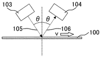
- the control device 101 is reflected by the plate material 100, the control unit 102 that controls the rotation of the first roll 202 and the second roll 203 of the plate material feed device 201, the transmission unit 103 that transmits the electromagnetic wave 105 toward the plate material 100, and the plate material 100. It is provided with a receiving unit 104 that receives the generated electromagnetic wave 106.
- the control unit 102 is connected to the plate material feed device 201 via the plate material feed control signal line 107, and controls the rotation of the first roll 202 and the second roll 203.
- the control unit 102 measures the transport speed v of the plate material 100 during a predetermined period determined by the control unit 102 based on the frequency of the electromagnetic wave 106 received by the reception unit 104.
- the control unit 102 measures the transfer amount of the plate material 100 conveyed to the processing device 301 during a predetermined period.
- the control unit 102 is provided separately from the plate material feeding device 201 and the processing device 301, but may be built in the plate material feeding device 201 or the processing device 301.
- the transmitting unit 103 and the receiving unit 104 are built in the processing device 301, but the plate material 100 is conveyed before or after the plate material 100 passes through the first roll 202 and the second roll 203. It may be built in the plate material feeding device 201 so that the amount can be measured, and can be provided at a required location.
- control device 101 may be built in the plate material feeding device 201 that conveys the plate material 100, or may be incorporated in a processing device 301 such as a press device that processes the plate material 100 conveyed from the plate material feeding device 201. good.
- the control unit 102 may measure the transport speed v of the plate material 100 by the difference between the frequency of the electromagnetic wave 105 transmitted by the transmission unit 103 and the frequency of the electromagnetic wave 106 received by the reception unit 104.
- the transmitting unit 103 transmits the electromagnetic wave 105 to the plate material 100 at an incident angle of ⁇
- the receiving unit 104 receives the electromagnetic wave 106 reflected from the plate material 100 at a reflection angle of ⁇ .
- the frequency f R of the electromagnetic wave 106 received by the receiving unit 104 is expressed by the Doppler effect in equation (1). Will be done.
- the control unit 102 mixes the electromagnetic wave 105 transmitted by the transmission unit 103 and the electromagnetic wave 106 received by the reception unit 104, and the frequency difference between these two electromagnetic waves 106 f T- f R to (2). A signal having the frequency of the equation can be obtained.
- the control unit 102 can measure the transport speed v of the plate material 100 from the frequency of the equation (2). Then, by measuring the transport speed v during the predetermined period, the length at which the plate material 100 is conveyed during the predetermined period, that is, the amount of the plate material 100 conveyed to the processing apparatus 301 during the predetermined period. Can be measured. In this way, even if the material 100 does not have a mark for measuring the conveyed amount such as a scale, the conveyed amount of the plate material 100 can be measured by the Doppler effect of electromagnetic waves.
- the transmission unit 103 transmits the electromagnetic wave 105 toward the plate material 100 from two directions.
- the transmission unit 103 includes an electromagnetic wave source, a beam splitter, and a mirror.
- the electromagnetic wave generated from the electromagnetic wave source of the transmission unit 103 is split into two by a beam splitter, one electromagnetic wave 105 is directly transmitted to the plate material 100 at an incident angle of ⁇ , and the other electromagnetic wave 105 is sent to the mirror. Is reflected and transmitted to the plate material 100 at an incident angle of ⁇ opposite to that of one electromagnetic wave 105.
- the frequency f R1 of the electromagnetic wave 106 when one of the electromagnetic waves 105 is reflected by the plate material 100 is determined by the Doppler effect. It is represented by the equation (3). Further, the frequency f R2 of the electromagnetic wave 106 when the other electromagnetic wave 105 is reflected by the plate material 100 is represented by the equation (4) by the Doppler effect.
- the electromagnetic wave 105 from two directions is reflected by the plate material 100, and the receiving unit 104 receives two electromagnetic waves 106 having different frequencies as an electromagnetic wave 106 having a frequency f R1 and an electromagnetic wave 106 having a frequency f R2.
- the control unit 102 heterodyne-processes these two electromagnetic waves 106 received by the receiving unit 104, and produces a signal having the frequency difference f R2- f R1 to (5) between the frequencies of these two electromagnetic waves 106. Obtainable.
- the control unit 102 can measure the transport speed v of the plate material 100 from the frequency of the equation (5). Then, by measuring the transport speed v during the predetermined period, the length at which the plate material 100 is conveyed during the predetermined period, that is, the amount of the plate material 100 conveyed to the processing apparatus 301 during the predetermined period. Can be measured. In this way, even if the material 100 does not have a mark for measuring the conveyed amount such as a scale, the conveyed amount of the plate material 100 can be measured by the Doppler effect of electromagnetic waves.
- the transmitting unit 103 is connected to the control unit 102 via the electromagnetic wave control signal line 108, and the receiving unit 104 is connected to the control unit 102 via the transport speed related signal line 109.
- the receiving unit 104 receives and conveys the electromagnetic wave 106 having a frequency as shown in the equations (1), (3), and (4), which is different from the frequency of the electromagnetic wave 105 transmitted by the transmitting unit 103 as described above.
- a carrier speed-related signal based on the frequency of the electromagnetic wave 106 received via the speed-related signal line 109 is transmitted to the control unit 102.
- the receiving unit 104 transmits a signal related to the frequency of the received electromagnetic wave 106 such as the equations (1), (3), and (4) to the control unit 102 via the transport speed related signal line 109.
- a signal related to the mixing process as in the equation (2) and the heterodyne process as in the equation (5) may be transmitted to the control unit 102 via the transport speed related signal line 109.
- These signals have a frequency, that is, a period based on the transport speed v of the plate material 100, as in the equations (1) to (5). It is sufficient that these signals include information related to the transport speed v of the plate material 100.
- the control unit 102 may control the receiving unit 104 so as to transmit a transfer speed-related signal to the control unit 102 when the plate material feeding device 201 is conveying the plate material 100. Further, the control unit 102 may control the transmission unit 103 so as to transmit the electromagnetic wave 105 toward the plate material 100 when the plate material feeding device 201 is transporting the plate material 100.
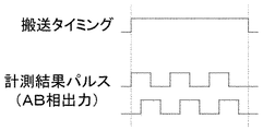
- the control unit 102 sets the transfer timing to H level via the electromagnetic wave control signal line 108, and the transmitting unit 103 transmits the electromagnetic wave 105 to the plate material 100. Control to send to.
- the receiving unit 104 receives the electromagnetic wave 106 reflected by the plate material 100, and transmits a measurement result pulse, which is a transport speed-related signal, to the control unit 102 via the transport speed-related signal line 109.
- the measurement result pulse may be an AB phase output whose phase is shifted by 90 ° with respect to each other as shown in FIG.
- the measurement result pulse has a frequency based on the transport speed v of the plate material 100, and the frequency increases as the transport speed v of the plate material 100 increases, and the frequency decreases as the transport speed v of the plate material 100 decreases. Based on the measurement result pulse, the amount of the plate material 100 conveyed to the processing device 301 is measured.
- the control unit 102 sets the transfer timing to L level via the electromagnetic wave control signal line 108, and the transmission unit 103 transfers the electromagnetic wave 105. It is controlled to stop the transmission to the plate material 100. In this way, the transport speed v of the plate material 100 during the period when the transport timing is H level can be measured, and the transport amount of the plate material 100 to the processing device 301 can be measured.
- control unit 102 may directly transmit the transfer timing to the reception unit 104.
- the receiving unit 104 transmits the transfer speed-related signal to the control unit 102 via the transfer speed-related signal line 109, and the control unit 102 sets the transfer timing.
- the receiving unit 104 stops transmitting the transport speed-related signal to the control unit 102. Further, the control unit 102 does not have to transmit the transfer timing to the transmission unit 103 and the reception unit 104.
- the receiving unit 104 constantly transmits the transport speed-related signal to the control unit 102 via the transport speed-related signal line 109, but the control unit 102 always transmits the transport speed-related signal from the receiving unit 104 for the entire period.
- the period in which the transfer timing is H level is extracted from the transfer speed-related signal of the plate material 100, and the transfer speed v of the plate material 100 is measured based on the transfer speed-related signal in the extracted period, and then measured. Based on the transfer speed v of the plate material 100, the transfer amount of the plate material 100 conveyed to the processing apparatus 301 during the extraction period is measured.
- the control unit 102 controls the rotation of the first roll 202 and the second roll 203 of the plate material feed device 201 via the plate material feed control signal line 107, thereby controlling the rotation of the first roll 202 and the second roll 203.
- the transfer of the plate material 100 is controlled by rotation.
- the predetermined period in which the amount of the plate material 100 conveyed to the processing device 301 is measured may be a period in which the plate material 100 is conveyed by the rotation of the first roll 202 and the second roll 203.
- the plate material feeding device 201 may further include a release device 204 for releasing the plate material 100 clamped by the first roll 202 and the second roll 203.
- the release device 204 may be connected to either the first roll 202 or the second roll 203, and the release device 204 raises and lowers the first roll 202 and / or the second roll 203 to move the plate material. 100 is clamped and released.
- the control unit 102 controls the transfer of the plate material 100 by controlling the release device 204 via the plate material feed control signal line 107.
- the predetermined period in which the amount of the plate material 100 conveyed to the processing device 301 is measured may be a period in which the plate material 100 is clamped by the first roll 202 and the second roll 203.
- the processing device 301 processes the plate material 100 conveyed from the plate material feeding device 201.
- the processing device 301 is a press device
- the processing device 301 includes an upper die 302 and a lower die 303, and the plate material 100 is formed by the cooperation of the upper die 302 and the lower die 303. It is punched out.
- the processing device 301 transmits a state signal regarding the state of the processing device 301, that is, a signal indicating whether the plate material 100 should be conveyed or the plate material 100 should be stopped, via the state signal line 111. Is transmitted to the control unit 102.
- the control unit 102 Based on the signal from the processing apparatus 301, the control unit 102 rotates the first roll 202 and the second roll 203, and the first roll 202 and the second roll 203 clamp the plate material 100. Etc., and further, as described above, a predetermined period in which the amount of the plate material 100 transported to the processing device 301 is measured is determined.
- the conveyed amount of the plate material 100 measured by the control unit 102 may be transmitted to the processing apparatus 301 via the conveyed amount signal line 110, or may be displayed on a display device such as a display.
- the plate material feeding device 201 intermittently conveys the plate material 100 to the processing device 301 by a constant amount, and the control device 101 of the present invention measures the amount of the plate material 100 conveyed to the processing device 301 by the plate material feeding device 201 with high accuracy. can do. Then, the measured transfer amount of the plate material 100 is used to adjust the transfer speed of the plate material 100 to the processing device 301, the transfer amount of the plate material 100 to the processing device 301, the stop position of the plate material 100 in the processing device 301, and the like. Can be used.
Landscapes
- Engineering & Computer Science (AREA)
- Mechanical Engineering (AREA)
- Physics & Mathematics (AREA)
- General Physics & Mathematics (AREA)
- Automation & Control Theory (AREA)
- Controlling Sheets Or Webs (AREA)
- Delivering By Means Of Belts And Rollers (AREA)
- Radar Systems Or Details Thereof (AREA)
Priority Applications (6)
| Application Number | Priority Date | Filing Date | Title |
|---|---|---|---|
| CN202180027528.6A CN115461169A (zh) | 2020-04-13 | 2021-04-09 | 板材进给装置用的控制装置 |
| EP21788983.1A EP4137246A4 (en) | 2020-04-13 | 2021-04-09 | CONTROL DEVICE FOR A PLATE FEEDING DEVICE |
| KR1020227035409A KR20220157989A (ko) | 2020-04-13 | 2021-04-09 | 판재 공급 장치를 위한 제어 장치 |
| JP2022515347A JPWO2021210500A1 (https=) | 2020-04-13 | 2021-04-09 | |
| US17/918,149 US20230147738A1 (en) | 2020-04-13 | 2021-04-09 | Control device for plate feeding device |
| JP2025010209A JP2025063293A (ja) | 2020-04-13 | 2025-01-24 | 板材送り装置のための制御装置 |
Applications Claiming Priority (2)
| Application Number | Priority Date | Filing Date | Title |
|---|---|---|---|
| JP2020-071508 | 2020-04-13 | ||
| JP2020071508 | 2020-04-13 |
Publications (1)
| Publication Number | Publication Date |
|---|---|
| WO2021210500A1 true WO2021210500A1 (ja) | 2021-10-21 |
Family
ID=78083878
Family Applications (1)
| Application Number | Title | Priority Date | Filing Date |
|---|---|---|---|
| PCT/JP2021/014992 Ceased WO2021210500A1 (ja) | 2020-04-13 | 2021-04-09 | 板材送り装置のための制御装置 |
Country Status (7)
| Country | Link |
|---|---|
| US (1) | US20230147738A1 (https=) |
| EP (1) | EP4137246A4 (https=) |
| JP (2) | JPWO2021210500A1 (https=) |
| KR (1) | KR20220157989A (https=) |
| CN (1) | CN115461169A (https=) |
| TW (1) | TWI906282B (https=) |
| WO (1) | WO2021210500A1 (https=) |
Citations (5)
| Publication number | Priority date | Publication date | Assignee | Title |
|---|---|---|---|---|
| JPS6435490U (https=) * | 1987-08-28 | 1989-03-03 | ||
| JPH05245555A (ja) * | 1992-03-04 | 1993-09-24 | Aida Eng Ltd | プレス機械の供給材料判別方法および判別装置 |
| JP2003112224A (ja) * | 2001-10-02 | 2003-04-15 | Amada Eng Center Co Ltd | H∞コントローラを用いた位置決め制御装置 |
| JP2004520934A (ja) * | 2000-11-16 | 2004-07-15 | ヴァムコ・インターナショナル・インコーポレイテッド | 材料送り機構に対して材料解除機構タイミングを決定及び設定する方法とシステム |
| JP2017181489A (ja) * | 2016-03-25 | 2017-10-05 | セイコーエプソン株式会社 | 光走査装置、搬送装置、特徴検出装置、媒体判別装置、仕分け装置、および、媒体の走査方法 |
Family Cites Families (23)
| Publication number | Priority date | Publication date | Assignee | Title |
|---|---|---|---|---|
| BE620662A (https=) * | 1961-07-25 | 1900-01-01 | ||
| DE2364539A1 (de) * | 1973-12-24 | 1975-07-10 | Berstorff Gmbh Masch Hermann | Einrichtung zum zufuehren eines zusammenhaengenden materialstreifens |
| IT1230509B (it) * | 1988-10-11 | 1991-10-25 | Fimi Spa | Macchina e metodo per il rallentamento di una serie di fogli di lamiera viaggianti in stretta successione lungo una linea di produzione |
| JP3043473B2 (ja) * | 1991-06-24 | 2000-05-22 | キヤノン株式会社 | シート材供給装置 |
| GB9220096D0 (en) * | 1992-09-23 | 1992-11-04 | Davis Decade Ltd | Operation of press tools |
| US5808465A (en) * | 1994-02-28 | 1998-09-15 | Vamco Machine & Tool, Inc. | Electronically controlled high speed press feed |
| JP4509548B2 (ja) * | 2003-12-24 | 2010-07-21 | オリンパス株式会社 | 搬送速度検出装置 |
| JP2005189169A (ja) * | 2003-12-26 | 2005-07-14 | Olympus Corp | 速度検出装置、搬送速度検出装置並びに画像形成装置 |
| JP4609500B2 (ja) * | 2008-02-20 | 2011-01-12 | 株式会社村田製作所 | 電子部品用キャリアテープの搬送装置及びコンピュータプログラム |
| DE102010009213A1 (de) * | 2010-02-25 | 2011-10-06 | Sms Siemag Ag | Verfahren und Vorrichtung zur Bestimmung der Geschwindigkeit eines Walzguts |
| EP2468429A1 (de) * | 2010-12-21 | 2012-06-27 | Siemens VAI Metals Technologies GmbH | Verfahren und Vorrichtung zur Messung der Geschwindigkeit eines Walzgutes |
| JP2015000768A (ja) * | 2013-06-13 | 2015-01-05 | セイコーエプソン株式会社 | 搬送装置、印刷装置、及び搬送方法 |
| KR102110645B1 (ko) * | 2013-12-24 | 2020-05-14 | 아르셀러미탈 | 열간 압연 방법 |
| JP6015966B2 (ja) * | 2014-04-17 | 2016-10-26 | コニカミノルタ株式会社 | 画像形成装置 |
| JP6549833B2 (ja) * | 2014-11-06 | 2019-07-24 | シャープ株式会社 | 人感知装置を備えた画像形成装置 |
| JP6608635B2 (ja) * | 2015-07-13 | 2019-11-20 | 株式会社三共製作所 | 板材送り装置 |
| JP6649133B2 (ja) * | 2016-03-09 | 2020-02-19 | コマツ産機株式会社 | ロールフィーダ、プレスシステム、およびフープ材搬送方法 |
| JP7085123B2 (ja) * | 2017-06-06 | 2022-06-16 | 株式会社リコー | 搬送装置、及び、画像形成装置 |
| DE102018207245A1 (de) * | 2018-05-09 | 2019-11-14 | Koenig & Bauer Ag | Druckmaschine und ein Verfahren zum Betreiben einer Druckmaschine |
| JP7193690B2 (ja) * | 2018-05-09 | 2022-12-21 | 東洋製罐株式会社 | フィルム加工システム及びフィルム加工方法 |
| JP2020027074A (ja) * | 2018-08-16 | 2020-02-20 | 株式会社豊田自動織機 | 検査装置 |
| WO2021032233A1 (de) * | 2019-08-16 | 2021-02-25 | Sms Group Gmbh | Verfahren zur online-ermittlung wenigstens eines walzparameters sowie walzwerk mit einer einrichtung zur online-ermittlung wenigstens eines walzparameters |
| US20240299997A1 (en) * | 2023-03-10 | 2024-09-12 | Honeywell International Inc. | Dynamic Roll Eccentricity Identification Using Extended Kalman Filter State Estimation and Control Upgrade for Cold Rolling Mills |
-
2021
- 2021-04-09 US US17/918,149 patent/US20230147738A1/en active Pending
- 2021-04-09 CN CN202180027528.6A patent/CN115461169A/zh active Pending
- 2021-04-09 KR KR1020227035409A patent/KR20220157989A/ko active Pending
- 2021-04-09 WO PCT/JP2021/014992 patent/WO2021210500A1/ja not_active Ceased
- 2021-04-09 JP JP2022515347A patent/JPWO2021210500A1/ja active Pending
- 2021-04-09 EP EP21788983.1A patent/EP4137246A4/en active Pending
- 2021-04-12 TW TW110113099A patent/TWI906282B/zh active
-
2025
- 2025-01-24 JP JP2025010209A patent/JP2025063293A/ja active Pending
Patent Citations (5)
| Publication number | Priority date | Publication date | Assignee | Title |
|---|---|---|---|---|
| JPS6435490U (https=) * | 1987-08-28 | 1989-03-03 | ||
| JPH05245555A (ja) * | 1992-03-04 | 1993-09-24 | Aida Eng Ltd | プレス機械の供給材料判別方法および判別装置 |
| JP2004520934A (ja) * | 2000-11-16 | 2004-07-15 | ヴァムコ・インターナショナル・インコーポレイテッド | 材料送り機構に対して材料解除機構タイミングを決定及び設定する方法とシステム |
| JP2003112224A (ja) * | 2001-10-02 | 2003-04-15 | Amada Eng Center Co Ltd | H∞コントローラを用いた位置決め制御装置 |
| JP2017181489A (ja) * | 2016-03-25 | 2017-10-05 | セイコーエプソン株式会社 | 光走査装置、搬送装置、特徴検出装置、媒体判別装置、仕分け装置、および、媒体の走査方法 |
Non-Patent Citations (1)
| Title |
|---|
| See also references of EP4137246A4 * |
Also Published As
| Publication number | Publication date |
|---|---|
| JP2025063293A (ja) | 2025-04-15 |
| TW202144100A (zh) | 2021-12-01 |
| EP4137246A4 (en) | 2024-05-22 |
| EP4137246A1 (en) | 2023-02-22 |
| CN115461169A (zh) | 2022-12-09 |
| KR20220157989A (ko) | 2022-11-29 |
| US20230147738A1 (en) | 2023-05-11 |
| JPWO2021210500A1 (https=) | 2021-10-21 |
| TWI906282B (zh) | 2025-12-01 |
Similar Documents
| Publication | Publication Date | Title |
|---|---|---|
| JP2009539282A5 (https=) | ||
| US20190018133A1 (en) | Object detection method and object detection device | |
| KR840001887A (ko) | 고무시이트 재료의 반송 성형장치(搬送成形裝置) | |
| WO2021210500A1 (ja) | 板材送り装置のための制御装置 | |
| EP2105802A3 (en) | Image forming apparatus | |
| ES8501340A1 (es) | Procedimiento y dispositivo para la aportacion con ajuste correcto de pliegos en maquinas elaboradas de pliegos | |
| EP1494045A3 (en) | Ground-speed measuring apparatus | |
| ATE458205T1 (de) | Radargerät | |
| US11726066B2 (en) | Inspection device and inspection method | |
| EP1666916A3 (en) | Tracking system | |
| JP2015169508A (ja) | 偏波レーダ装置 | |
| EP0361071A3 (de) | Verfahren und Einrichtung zum Zählen von in Schuppenformation anfallenden flachen Gegenständen wie Druckbogen, Zeitschriften und dgl. | |
| GB2629516A (en) | Sidelink positioning reference signal processing | |
| CN107505476B (zh) | 一种直线距离上平均流体流速测量系统 | |
| TW200840787A (en) | Sheet-conveying apparatus and method for detection of multiple documents thereof | |
| US3684962A (en) | Retransmitting system for use in locating remote signals | |
| JPH0210059B2 (https=) | ||
| JP2002048529A (ja) | 送信器と受信器との間の位相シフトを補正する方法及び装置 | |
| JP2025063293A5 (https=) | ||
| US2901745A (en) | Signal processing arrangement | |
| JP2000025988A (ja) | 超音波を利用したシート材の重送検知方法 | |
| KR20030088354A (ko) | 지엽류 압인 장치 | |
| FR3101955B1 (fr) | Dispositif et procede de mesure de distance par ultrasons | |
| WO2024056057A3 (zh) | 一种处理装置及电子设备 | |
| CN101314443A (zh) | 纸张馈送装置及其侦测多张进纸的方法 |
Legal Events
| Date | Code | Title | Description |
|---|---|---|---|
| 121 | Ep: the epo has been informed by wipo that ep was designated in this application |
Ref document number: 21788983 Country of ref document: EP Kind code of ref document: A1 |
|
| ENP | Entry into the national phase |
Ref document number: 20227035409 Country of ref document: KR Kind code of ref document: A Ref document number: 2022515347 Country of ref document: JP Kind code of ref document: A |
|
| NENP | Non-entry into the national phase |
Ref country code: DE |
|
| ENP | Entry into the national phase |
Ref document number: 2021788983 Country of ref document: EP Effective date: 20221114 |