WO2021210269A1 - 映像分析装置、映像分析システム及び映像分析方法 - Google Patents
映像分析装置、映像分析システム及び映像分析方法 Download PDFInfo
- Publication number
- WO2021210269A1 WO2021210269A1 PCT/JP2021/006512 JP2021006512W WO2021210269A1 WO 2021210269 A1 WO2021210269 A1 WO 2021210269A1 JP 2021006512 W JP2021006512 W JP 2021006512W WO 2021210269 A1 WO2021210269 A1 WO 2021210269A1
- Authority
- WO
- WIPO (PCT)
- Prior art keywords
- video analysis
- unit
- video
- frame
- detection
- Prior art date
- Legal status (The legal status is an assumption and is not a legal conclusion. Google has not performed a legal analysis and makes no representation as to the accuracy of the status listed.)
- Ceased
Links
Images









Classifications
-
- G—PHYSICS
- G06—COMPUTING OR CALCULATING; COUNTING
- G06V—IMAGE OR VIDEO RECOGNITION OR UNDERSTANDING
- G06V20/00—Scenes; Scene-specific elements
- G06V20/50—Context or environment of the image
- G06V20/56—Context or environment of the image exterior to a vehicle by using sensors mounted on the vehicle
-
- G—PHYSICS
- G06—COMPUTING OR CALCULATING; COUNTING
- G06T—IMAGE DATA PROCESSING OR GENERATION, IN GENERAL
- G06T7/00—Image analysis
- G06T7/20—Analysis of motion
- G06T7/215—Motion-based segmentation
-
- G—PHYSICS
- G06—COMPUTING OR CALCULATING; COUNTING
- G06T—IMAGE DATA PROCESSING OR GENERATION, IN GENERAL
- G06T1/00—General purpose image data processing
- G06T1/20—Processor architectures; Processor configuration, e.g. pipelining
-
- H—ELECTRICITY
- H04—ELECTRIC COMMUNICATION TECHNIQUE
- H04N—PICTORIAL COMMUNICATION, e.g. TELEVISION
- H04N21/00—Selective content distribution, e.g. interactive television or video on demand [VOD]
- H04N21/20—Servers specifically adapted for the distribution of content, e.g. VOD servers; Operations thereof
- H04N21/23—Processing of content or additional data; Elementary server operations; Server middleware
- H04N21/234—Processing of video elementary streams, e.g. splicing of video streams or manipulating encoded video stream scene graphs
- H04N21/2343—Processing of video elementary streams, e.g. splicing of video streams or manipulating encoded video stream scene graphs involving reformatting operations of video signals for distribution or compliance with end-user requests or end-user device requirements
- H04N21/234381—Processing of video elementary streams, e.g. splicing of video streams or manipulating encoded video stream scene graphs involving reformatting operations of video signals for distribution or compliance with end-user requests or end-user device requirements by altering the temporal resolution, e.g. decreasing the frame rate by frame skipping
-
- H—ELECTRICITY
- H04—ELECTRIC COMMUNICATION TECHNIQUE
- H04N—PICTORIAL COMMUNICATION, e.g. TELEVISION
- H04N21/00—Selective content distribution, e.g. interactive television or video on demand [VOD]
- H04N21/40—Client devices specifically adapted for the reception of or interaction with content, e.g. set-top-box [STB]; Operations thereof
- H04N21/43—Processing of content or additional data, e.g. demultiplexing additional data from a digital video stream; Elementary client operations, e.g. monitoring of home network or synchronising decoder's clock; Client middleware
- H04N21/44—Processing of video elementary streams, e.g. splicing a video clip retrieved from local storage with an incoming video stream or rendering scenes according to encoded video stream scene graphs
- H04N21/44008—Processing of video elementary streams, e.g. splicing a video clip retrieved from local storage with an incoming video stream or rendering scenes according to encoded video stream scene graphs involving operations for analysing video streams, e.g. detecting features or characteristics in the video stream
-
- G—PHYSICS
- G06—COMPUTING OR CALCULATING; COUNTING
- G06T—IMAGE DATA PROCESSING OR GENERATION, IN GENERAL
- G06T2210/00—Indexing scheme for image generation or computer graphics
- G06T2210/12—Bounding box
-
- H—ELECTRICITY
- H04—ELECTRIC COMMUNICATION TECHNIQUE
- H04N—PICTORIAL COMMUNICATION, e.g. TELEVISION
- H04N7/00—Television systems
- H04N7/18—Closed-circuit television [CCTV] systems, i.e. systems in which the video signal is not broadcast
Definitions
- the present invention relates to a video analyzer, a video analysis system, and a video analysis method.
- Non-Patent Document 1 discloses a technique for performing video analysis in a distributed manner by a plurality of video analysis units for a series of video frames.
- Non-Patent Document 1 still has a problem that the accuracy of video analysis is not sufficient.
- the present invention has been made to solve such a problem, and an object of the present invention is to provide an image analysis device, an image analysis system, and an image analysis method having improved image analysis accuracy.
- the video analyzer is An image analyzer equipped with a first image analysis unit and a second image analysis unit.
- the first video analysis unit A distribution unit that distributes at least two frames to the first video analysis unit or the second video analysis unit, A first detection unit that detects an object in a frame distributed to the first video analysis unit, and a first detection unit.
- An acquisition unit that acquires information on movement associated with the detected object and transmits the information on the movement and the detection result in the first detection unit to the second video analysis unit.
- the second video analysis unit A second detection unit that detects an object in the frame received from the distribution unit, and An adjustment unit that adjusts the detection result of the first detection unit based on the detection result of the second detection unit and information on the movement, and an adjustment unit. To be equipped.
- the video analysis system is A video analysis system including a first video analysis unit and a second video analysis unit.
- the first video analysis unit A distribution unit that distributes at least two frames to the first video analysis unit or the second video analysis unit, A first detection unit that detects an object in a frame distributed to the first video analysis unit, and a first detection unit.
- An acquisition unit that acquires information on movement associated with the detected object and transmits the information on the movement and the detection result in the first detection unit to the second video analysis unit.
- the second video analysis unit A second detection unit that detects an object in the frame received from the distribution unit, and An adjustment unit that adjusts the detection result of the first detection unit based on the detection result of the second detection unit and information on the movement, and an adjustment unit. To be equipped.
- the video analysis method is This is a video analysis method in which the first video analysis unit and the second video analysis unit perform video analysis in a distributed manner for a series of frames.
- the first video analysis unit At least two frames are received in succession, and it is determined whether to analyze by the first video analysis unit or the second video analysis unit.
- the objects in the sorted frames are detected, and Information on the movement associated with the detected object is acquired, and the information on the movement and the detection result in the first video analysis unit are transmitted to the second video analysis unit.
- the object in the frame received from the first video analysis unit is detected, and the object is detected.
- the detection result in the first video analysis unit is adjusted based on the detection result in the second video analysis unit and the information regarding the movement.
- an image analysis device it is possible to provide an image analysis device, an image analysis system, and an image analysis method with improved image analysis accuracy.
- FIG. 5 is a diagram showing a video frame including an exemplary object detected by the first video analysis unit according to the third embodiment. It is a figure explaining the example of calculating the movement vector which concerns on Embodiment 3.
- FIG. 5 is a diagram showing a video frame including an exemplary object detected by the first video analysis unit according to the third embodiment. It is a figure explaining the example of calculating the movement vector which concerns on Embodiment 3.
- FIG. 5 is a diagram showing a frame including an exemplary object detected by the second video analysis unit according to the third embodiment. It is a conceptual diagram explaining the whole picture of the adjustment process which concerns on some Embodiments. It is a conceptual diagram explaining the specific example of the adjustment process which concerns on some Embodiments. It is a flowchart which shows the operation of the 1st video analysis part arranged on the edge side which concerns on Embodiment 3.
- FIG. FIG. 5 is a flowchart showing an operation related to video frame reception of the second video analysis unit arranged on the cloud side according to the third embodiment. It is a flowchart which shows the operation by the analysis result adjustment part arranged on the cloud side which concerns on Embodiment 3.
- FIG. It is a block diagram which shows the structural example of the hardware of the image analyzer or the image analysis part.
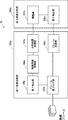
- FIG. 1 is a block diagram showing a configuration of a video analyzer according to the first embodiment.
- the video analysis device 1 includes a first video analysis unit 100 and a second video analysis unit 200 in order to disperse and process at least two frames.
- the video analyzer 1 can be implemented by one or more computers. At least two frames may be two consecutive frames or two frames sandwiching another frame.
- the first video analysis unit 100 has a distribution unit 103 that distributes at least two frames to the first image analysis unit 100 or the second image analysis unit 200, and a frame that is distributed when analyzed by the first video analysis unit 100.
- the first detection unit 105 that detects the object and the information about the movement associated with the detected object are acquired, and the information about the movement and the detection result by the first detection unit 105 are transmitted to the second video analysis unit 200.
- the acquisition unit 106 for transmission is provided.
- the first detection unit 105 detects a predetermined object from the frame by using a predetermined video analysis program.
- the distribution unit 103 can distribute frames to the first video analysis unit 100 or the second video analysis unit 200 at a preset distribution rate.
- the "information about the movement associated with the detected object" may include, for example, information on the moving direction of the object or a movement vector in the bounding box surrounding the object.
- the second video analysis unit 200 is a first detection unit based on the second detection unit 205 that detects an object in the frame from the distribution unit 103, the detection result of the second detection unit 205, and the information related to the movement.
- An adjusting unit 207 for adjusting the detection result in 105 is provided.
- the second detection unit 205 detects a predetermined object from the frame by using a predetermined video analysis program.
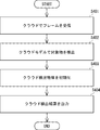
- FIG. 2 is a flowchart showing the video analysis method according to the first embodiment.
- the video analysis method according to the first embodiment at least two frames are distributed and processed by the first video analysis unit 100 and the second video analysis unit 200.
- the first video analysis unit 100 At least two frames received in succession are distributed to the first video analysis unit 100 or the second video analysis unit 200 (step S101).
- An object in the frame distributed to the first video analysis unit 100 is detected (step S102).
- Information on the movement associated with the detected object is acquired, and the information on the movement and the detection result in the first video analysis unit 100 are transmitted to the second video analysis unit 200 (step S103).
- the second video analysis unit 200 detects an object in the frame received from the first video analysis unit 100 (step S103).
- the second video analysis unit 200 adjusts the detection result of the first video analysis unit 100 based on the detection result of the second video analysis unit 200 and the information regarding the movement (step S105).
- FIG. 3 is a block diagram showing a configuration of the video analyzer according to the second embodiment.
- the video analysis device 1 includes a first video analysis unit 100a and a second video analysis unit 200a in order to disperse and process a series of frames (including at least two frames).
- the first video analysis unit 100a distributes at least two series of frames received from the camera to the first video analysis unit 100a, the second video analysis unit 200a, the distribution unit 103a, and the first video analysis unit 100.
- the first detection unit 105a that detects the object in the frame, the movement information acquisition unit 106a that acquires the information about the movement in the detected object, the information about the movement, and the detection result by the first detection unit 105a are the first.
- the analysis result transmission unit 107a for transmitting to the two video analysis units and the frame transmission unit 109a for transmitting the frames distributed to the second video analysis unit 200a to the second video analysis unit 200a are provided.
- the first detection unit 105a detects a predetermined object from the frame by using a predetermined video analysis program.
- the detected object can be surrounded by a bounding box.
- the movement information acquisition unit 106a recognizes that the object is moving between the two frames, and acquires the movement information about the object in the bounding box.
- the movement information acquisition unit 106a compares the video frame temporarily stored in the storage unit in the first video analysis unit 100a with the detection result frame from the first detection unit 105a to acquire the movement information. Can be done.
- the acquired movement information may include information on the moving direction of the object or a movement vector.
- the distribution unit 103 can distribute frames to the first video analysis unit 100 or the second video analysis unit 200 at a preset distribution rate.
- the distribution unit 103 when the distribution rate is set to 10%, the distribution unit 103 counts consecutively received frames using the distribution counter, transmits the first frame to the second video analysis unit 200, and then the rest. The nine frames can be distributed to the first video analysis unit 100.
- the distribution rate is set to be equal to or higher than the threshold value.
- the "information regarding the movement of the detected object in the detection area" may include, for example, information on the moving direction of the object in the bounding box surrounding the object or a movement vector.
- the frame transmission unit 109a may include an encoder that encodes a video frame with a predetermined quality.
- the first video analysis unit 100a includes an analysis result transmission unit 107a and a frame transmission unit 109a.
- the analysis result transmission unit 107a transmits the movement vector for the frame distributed to the first video analysis unit 100a and the detection result as the analysis result to the second video analysis unit 200a. Therefore, the transmission data capacity per frame of the analysis result transmission unit 107a is relatively small.
- the frame transmission unit 109a encodes and transmits the frames distributed to the second video analysis unit 200a with a predetermined quality, the transmission data capacity per frame of the frame transmission unit 109a is determined by the analysis result transmission unit 107a. growing.
- the analysis result transmission unit 107a and the frame transmission unit 109a are different frames, that is, the frame distributed to the first video analysis unit 100a in the distribution unit 103a and the second video analysis unit. It deals with the frames allocated to 200a.
- the second video analysis unit 200a performs the first detection based on the second detection unit 205a that detects the object in the frame received from the frame transmission unit 109a and the detection result and the information on the movement by the second detection unit 205a.
- An adjusting unit 207a for adjusting the detection result of the unit 105a is provided.
- the second detection unit 205a detects a predetermined object from the frame by using a predetermined video analysis program different from or more accurate than the video analysis program of the first detection unit 105a.
- FIG. 4 is a flowchart showing the video analysis method according to the second embodiment.
- the video analysis method according to the second embodiment at least two frames are distributed and processed by the first video analysis unit 100 and the second video analysis unit 200.
- the first video analysis unit 100a separately distributes a series of frames received from the camera to the first video analysis unit 100a or the second video analysis unit 200a (step S201).
- the first video analysis unit 100a detects an object in the frame distributed to the first video analysis unit 100a (step S202).
- the first video analysis unit 100a acquires information regarding the movement of the detected object in the detection area (for example, the bounding box) (step S203).
- the first video analysis unit 100a transmits information on movement and the detection result of the first video analysis unit 100a to the second video analysis unit 200a (step S204).
- the first video analysis unit 100a transmits the frames allocated to the second video analysis unit 200a to the second video analysis unit 200a (step S205).
- the second video analysis unit 200a detects an object in the frame received from the first video analysis unit 100a (step S206).
- the detection result in the first video analysis unit 100a is adjusted based on the detection result in the second video analysis unit 200a and the information regarding the movement received from the first video analysis unit 100a (step S207).
- FIG. 5 is a block diagram showing the structure of the video analysis system according to the third embodiment.
- the video analysis system 1b includes a first video analysis unit 100b and a second video analysis unit 200b.
- the first video analysis unit 100b is arranged on the edge side and is connected to the camera by wire or wirelessly.
- wireless communication such as Wi-Fi (registered trademark)
- the number of connections is small, so that the communication is stable as compared with the mobile phone network such as 4G and 5G. Is possible.
- the first video analysis unit 100b cannot prepare sufficient calculation resources due to restrictions on the power supply and installation space, and often becomes a low-precision model with low calculation cost.
- the second video analysis unit 200 is connected to the first video analysis unit 100 via a wireless network such as LTE (registered trademark), 5G, or Wi-fi (registered trademark), and is compared with the first video analysis unit 100b.
- LTE registered trademark
- 5G Fifth Generation
- Wi-fi registered trademark
- the first video analysis unit 100b is, for example, an in-vehicle video analysis device that can be realized by a computer.
- the first video analysis unit 100b is, for example, a ROM (Read Only) in which a processor 1202 such as a CPU (Central Processing Unit) that performs arithmetic processing and the like, an arithmetic program executed by the processor 1202, and the like are stored. It is composed of a memory 1203 composed of a memory) and a RAM (RandomAccessMemory), a microcomputer composed of an interface unit (I / F) 1201 for inputting / outputting signals to and from the outside, and the like.
- a ROM Read Only
- a processor 1202 such as a CPU (Central Processing Unit) that performs arithmetic processing and the like, an arithmetic program executed by the processor 1202, and the like are stored.
- It is composed of a memory 1203 composed of a memory) and a RAM (RandomAccessMemory),
- the processor 1202, the memory 1203, and the interface unit 1201 are connected to each other via a data bus or the like.
- the interface unit (I / F) 1201 may be used to perform wireless LAN communication specified in the IEEE 802.11 series or mobile communication specified in 3GPP (3rd Generation Partnership Project).
- the interface unit (I / F) 1201 may include, for example, a network interface card (NIC) compliant with the IEEE802.3 series.
- NIC network interface card
- the first video analysis unit 100b includes a video frame reception unit 101b, a frame distribution unit 103b, a change unit 104b, a first detection unit 105b, a movement vector acquisition unit 106b, an analysis result transmission unit 107b, and an encoder 108b. And the storage unit 110b.
- the video frame receiving unit 101b continuously receives one or more video frames from an in-vehicle camera (not shown) via a wired network.
- an in-vehicle camera will be described as an example, but another camera such as a fixed camera may be used.
- Each received video frame is temporarily stored in the storage unit 110b.
- the frame distribution unit 103b determines whether each video frame from the video frame reception unit 101b is analyzed by the first video analysis unit 100b or the second video analysis unit 200b by a predetermined frame transmission ratio (also known as the distribution rate). (Sometimes called). For example, when the predetermined frame transmission ratio is set to 10%, out of 10 continuously received video frames, 9 frames are transmitted after transmitting 1 frame to the 2nd video analysis unit 200b. Allocate to the first video analysis unit 100b.
- the frame distribution unit 103b distributes continuously received video frames at a predetermined frame transmission ratio or more so that the second video analysis unit 200b analyzes them.
- the predetermined frame transmission ratio can be set based on the available band of the wireless network from the first video analysis unit 100b to the second video analysis unit 200b.
- the frame distribution unit 103b estimates a usable band indicating a band that can be used for transmitting data on the wireless network. For example, the frame distribution unit 103b may evaluate the usable band by a level-divided value (for example, large, medium, small), and change the frame transmission ratio step by step based on the evaluated usable band (details). Will be described later).
- a level-divided value for example, large, medium, small
- the encoder 108b When the encoder 108b receives the video frame sorted so as to be analyzed by the second video analysis unit 200b from the frame sorting unit 103b, the encoder 108b encodes the video frame with a predetermined quality and analyzes the encoded video frame in the second video analysis. It is transmitted to the unit 200b.
- the video frame distributed by the frame distribution unit 103b so as to be analyzed by the first video analysis unit 100b is sent to the first detection unit 105b.
- the first detection unit 105b detects an object in the sorted frame. Specifically, the first detection unit 105b uses the image analysis program A (sometimes also referred to as an edge model, a lightweight model, or a low-precision model) with respect to the image frame distributed by the frame distribution unit 103b. Perform image analysis.
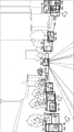
- FIG. 6 is a diagram showing a video frame including an exemplary object detected by the first video analysis unit.
- An example of a lightweight model is YOLOv3 Tiny, which has slightly inferior recognition accuracy but can operate at high speed.
- FIG. 6 shows an exemplary video frame in which an in-vehicle camera of a moving vehicle captures the front.
- traffic-related objects such as automobiles, trucks, buses, motorcycles, bicycles, pedestrians, and traffic lights are detected.
- each detected object is surrounded by a bounding box.
- the notation "Car: 3%" shown in the vicinity of the bounding box indicates that the probability (reliability) that the detection target is an automobile is 3%.
- objects related to traffic about 1 to 200 objects can be detected per frame.
- the movement vector acquisition unit 106b acquires the movement vector in the object detected by the first detection unit 105b between the two frames. That is, the movement vector acquisition unit 106b can acquire the movement vector by comparing the luminance gradient between the detection result frame from the first detection unit 105b and the frame stored in the storage unit 110b.
- FIG. 7 is a diagram illustrating an example of calculating a movement vector.
- FIG. 7A shows a detected vehicle in a video frame taken at time t.
- the movement vector acquisition unit 106b acquires the average value of the movement vectors in the bounding box shown by the broken line. This movement vector can be used to calculate how much the two frames are and adjust the detection position.
- the two frames may be two consecutive frames in chronological order (for example, t-1, t) or two frames separated by a predetermined time (for example, t-5, t).
- the movement vector is obtained by using the Gunnar Farneback method for Optical Flow. That is, first, movement vectors in the x-direction and the y-direction are generated per pixel in the entire frame. After that, the average vector in the detection area (for example, the bounding box) of each edge object is calculated. As a result, it is possible to recognize in which direction each detection object is moving between frames.
- FIG. 7B shows a shifted automobile based on the movement vector acquired by the adjustment unit 207b (that is, FIG. 7B shows an estimated video frame at time t + 1).
- the solid bounding box indicates the bounding box after the shift.
- the object can be moved for a predetermined time based on the movement vector.
- the data capacity can be significantly reduced by focusing only on the movement vector associated with the detected object or the bounding box instead of the movement vector of the entire two frames in this way.
- the analysis result transmission unit 107b transmits the object detected by the first detection unit 105 and the movement vector acquired by the movement vector acquisition unit 106 to the second video analysis unit 200b via the wireless network as the analysis result. do.
- the analysis result may include, for example, the center coordinates (x, y) of the bounding box, the width, the height, the identifier of the detected object, the number of detected objects, and the movement vector (x, y). That is, the analysis result transmission unit 107b transmits such an analysis result to the second video analysis unit 200b instead of the video frame itself analyzed by the first video analysis unit 100b.
- the transmission data capacity is reduced and the occurrence of problems (block noise, frame dropping, etc.) due to insufficient bandwidth is suppressed as compared with the case where the video frame itself analyzed by the first video analysis unit 100b is transmitted.
- the second video analysis unit 200b is, for example, a cloud server that can be realized by a computer.
- the second video analysis unit 200b is a ROM (Read Only) in which a processor 1202 such as a CPU (Central Processing Unit) that performs arithmetic processing and the like, an arithmetic program executed by the processor 1202, and the like are stored. It is composed of a memory 1203 composed of a memory) and a RAM (RandomAccessMemory), a microcomputer composed of an interface unit (I / F) 1201 for inputting / outputting signals to and from the outside, and the like.
- a processor 1202 such as a CPU (Central Processing Unit) that performs arithmetic processing and the like, an arithmetic program executed by the processor 1202, and the like are stored.
- It is composed of a memory 1203 composed of a memory) and a RAM (RandomAccessMemory), a microcomputer composed of an interface unit (I / F) 1201 for
- the processor 1202, the memory 1203, and the interface unit 1201 are connected to each other via a data bus or the like.
- the interface unit (I / F) may be used to perform wireless LAN communication specified in the IEEE 802.11 series or mobile communication specified in 3GPP (3rd Generation Partnership Project).
- the interface unit (I / F) 1201 may include, for example, a network interface card (NIC) compliant with the IEEE802.3 series.
- NIC network interface card
- the second video analysis unit 200b includes a decoder 201b, an analysis result receiving unit 203b, a second detection unit 205b, an analysis result adjusting unit 207b, and a band estimation unit 212b.
- the decoder 201b decodes the video frame encoded by the encoder 108b and transmits the video frame to the second detection unit 205b.
- the decoder 201b may include a frame buffer that receives video frames from the encoder 108 and temporarily stores them.
- the second detection unit 205b detects an object in the sorted frame.
- the second detection unit 205b is also called a video analysis program B (also called a cloud model or a high-precision model) capable of performing video analysis with higher accuracy than the video analysis program A for the video frame from the decoder 201. Perform image analysis in).
- An example of a high-precision model is Mask RCNN, which performs general object detection and segmentation.
- FIG. 8 is a diagram showing a video frame including an exemplary object detected by the second video analysis unit.
- FIG. 8 shows the result of detecting an object with a high-precision model in the same video frame as in FIG. In this example, as shown in FIG.
- FIG. 8 traffic-related objects such as automobiles, bicycles, pedestrians, and traffic lights are detected. Each detected object is surrounded by a bounding box.
- the notation “Car: 99%” shown in the vicinity of the bounding box indicates that the probability (reliability) that the detection target is an automobile is 99%.
- FIG. 8 shows that the object is detected with higher reliability than that of FIG.
- the analysis result receiving unit 203b receives the analysis result from the analysis result transmitting unit 107b.
- the analysis result receiving unit 203b may be an analysis result data buffer for temporarily storing the analysis result data.
- the analysis result adjustment unit 207b adjusts the video frame based on the video frame in which the object is detected by the second detection unit 205b (the object is surrounded by a bounding box) and the movement vector. Specifically, the analysis result adjusting unit 207b adjusts the video frame shot after the video frame based on the video frame in which the object is detected by the second detection unit 205b and the movement vector. The analysis result adjustment unit 207b is detected by the first detection unit 105b based on, for example, a video frame in which the object is detected by the second detection unit 205b (the object is surrounded by a bounding box) and a movement vector. From the result, adjust the position of the object.
- the analysis result adjusting unit 207b adjusts the detection result of the low-precision model by the first detection unit 105b with reference to the detection result of the high-precision model of the second detection unit 205b.
- the analysis result adjustment unit 207b refers to the video frame detected by the high-precision model of the second detection unit 205b, and the video image taken after the video frame and distributed to the first detection unit 105 (low-precision model). Estimate the frame with high accuracy.
- the band estimation unit 212b can be used to transmit data via a wireless network from the first video analysis unit 100b to the second video analysis unit 200b with reference to the usage amount of the analysis result data buffer and the frame buffer described above. Estimate the usable band that indicates a certain band. The band estimation unit 212b notifies the change unit 104 of the first video analysis unit 100b of the estimated usable band (for example, large, medium, small).
- the change unit 104b changes the frame transmission ratio of the frame distribution unit 103b based on the estimated usable band. For example, when the usable band is large, the changing unit 104b may change the frame transmission ratio to a high value to increase the analysis ratio in the cloud. Alternatively, when the usable band is small, the changing unit 104b may change the frame transmission ratio to a low value and increase the analysis ratio at the edge.
- FIG. 9 is a conceptual diagram illustrating an overall picture of the adjustment process according to some embodiments.
- the frame shown by the solid line indicates the frame sent to the cloud.
- the frame shown by the broken line indicates the frame distributed to the edge.
- the frame distribution unit 103b transmits frames to the second video analysis unit 200 on the cloud side at a frame transmission rate of 25%. That is, the frame (shown by the solid line) taken at time t is sent to the second video analysis unit 200b on the cloud side.
- the object is detected by the high-precision model of the second detection unit 205b on the cloud side.
- a frame in which an object is detected on the cloud side is called a reference frame.
- the object is detected by the first detection unit 105 of the first video analysis unit 100b on the edge side. Further, for the frame photographed at the time t + 1, the movement vector in the bounding box surrounding the detection target is acquired by the movement vector acquisition unit 106b.
- These detection results also referred to as edge detection results in the present specification
- movement vectors are sent by the analysis result transmission unit 107b to the analysis result reception unit 203b of the second video analysis unit 200b.
- the analysis result adjusting unit 207b sets the time based on the detection result (also referred to as the cloud detection result in the present specification) by the second detection unit 205b on the cloud side for the frame at time t and the movement vector for the frame at time t + 1. Adjust the edge detection result for the t + 1 frame.
- the object is detected by the first detection unit 105b of the first video analysis unit 100b on the edge side.
- the movement vector acquisition unit 106b acquires the movement vector in the bounding box surrounding the detection target.
- These edge detection results and movement vectors are sent by the analysis result transmission unit 107b to the analysis result receiving unit 203b of the second video analysis unit 200b.
- the analysis result adjusting unit 207b adjusts the edge detection result for the frame at time t + 2 based on the adjusted result for the frame at time t + 1 and the movement vector for the frame at time t + 2.
- the object is detected by the first detection unit 105b of the first video analysis unit 100b on the edge side.
- the movement vector acquisition unit 106b acquires the movement vector in the bounding box surrounding the detection target.
- These edge detection results and movement vectors are sent by the analysis result transmission unit 107b to the analysis result receiving unit 203b of the second video analysis unit 200b.
- the analysis result adjustment unit 207b adjusts the edge detection result for the frame at time t + 3 based on the adjusted result for the frame at time t + 2 and the movement vector for the frame at time t + 3.
- the frame shot at time t + 4 is sent to the second video analysis unit 200b on the cloud side again by the frame distribution unit 103. Then, in the frame, the object is detected by the high-precision model of the second detection unit 205b on the cloud side. That is, the frame taken at the time t + 4 becomes the reference frame, and the adjustment process after the time t + 5 is performed.
- the frame transmission ratio is set to 25%, but the present invention is not limited to this.
- the shooting interval between frames can be set arbitrarily.
- the adjusted result of the immediately preceding t + 1 or t + 2 frame is used as a reference, but the reference frame may be used as a reference. That is, the edge detection result for the frame at time t + 2 may be adjusted based on the cloud detection result for the frame at time t and the movement vector for the frame at time t + 2 with reference to the reference frame at time t. Similarly, the edge detection result for the frame at time t + 3 may be adjusted based on the cloud detection result for the frame at time t and the movement vector for the frame at time t + 3 with reference to the reference frame at time t. ..
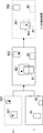
- FIG. 10 is a conceptual diagram illustrating a specific example of the operation of the analysis result adjusting unit 207b.
- the analysis result adjustment unit 207b of the second video analysis unit 200b on the cloud side uses the cloud detection result for the frame captured at time t, the edge detection result for the frame captured at time t + 1, and the movement vector at time t + 1. Estimate the exact result in.
- the frame shot at time t is detected by the second detection unit 205b of the second video analysis unit 200b on the cloud side.
- the frame shows two bounding boxes B1 and B2 (also referred to as cloud detection objects) surrounding the two detected objects.
- the object is detected by the first detection unit 105b of the first video analysis unit 100 on the edge side.
- two bounding boxes B21 and B22 also referred to as edge detection objects surrounding the two detected objects are shown in the frame.
- the frame itself is not sent to the second video analysis unit 200b on the cloud side, and the detection result of the object (bounding boxes B21, B22) and the average value of the movement vectors in each bounding are the second video. It is sent to the analysis unit 200b.
- the analysis result adjustment unit 207b arranges the bounding boxes B21 and B22 photographed at time t + 1 on the reference frame photographed at time t.
- the bounding box B1 is moved to the bounding box B12 based on the average moving vector in the bounding box B11 by the shooting interval between these frames (in FIG. 9, the cloud object after the movement).
- the bounding box B2 in the frame at time t no object is detected in the frame at time t + 1 (that is, there is no bounding box overlapping with the bounding box B2 in the frame at time t + 1). That is, it is considered that the object in the bounding box B2 in the frame at time t is framed out by the movement of the object in the frame at time t + 1. Therefore, the bounding box B2 is deleted from the estimation result at time t + 1.
- the bounding box B22 in the frame at time t + 1 no object is detected in the frame at time t (that is, there is no bounding box that overlaps with the bounding box B22 in the frame at time t).
- the object in the bounding box B22 in the frame at time t + 1 is considered to have newly appeared (in FIG. 9, the edge new detection object). Therefore, the bounding box B22 is kept in the estimation result at time t + 1.
- the analysis result adjustment unit 207b on the cloud side adjusts the edge detection result at time t + 1, and as shown in FIG. 10, a more accurate analysis result at time t + 1 (adjusted result in FIG. 9). Can be estimated.
- the analysis result at the estimated time t + 1 (the adjusted result of t + 1 in FIG. 9) is referred to in the frame adjustment process at time t + 2 (see FIG. 9).
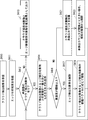
- FIG. 11 is a flowchart showing the operation of the first video analysis unit arranged on the edge side according to the third embodiment.
- the first video analysis unit 100b first initializes (step S301). Here, the frame distribution counter and the like are initialized.
- the video frame receiving unit 101b receives a video frame from an in-vehicle camera (not shown) (step S302).
- the frame distribution unit 103b distributes whether the video frame is analyzed by the second video analysis unit 200b on the cloud side or the first detection unit 105b on the edge side (step S303).
- the encoder 108b encodes the video frame with a predetermined quality and transmits it to the second video analysis unit 200 (step).
- step S304 the encoder 108b encodes the video frame with a predetermined quality and transmits it to the second video analysis unit 200 (step).
- the first detection unit 105b uses the edge model (lightweight model) to display the object in the video frame. Is detected (step S305). Subsequently, the moving vector acquisition unit 106 acquires the average moving vector in the bounding box surrounding the detected object (step S306). The analysis result transmission unit 107b transmits the detection result of each object and the movement vector of each object to the second video analysis unit 200b (step S307). Subsequently, when the video frame receiving unit 101b receives the subsequent frames from the camera in chronological order (returning to step S302), the above process is repeated.
- the edge model lightweight model
- FIG. 12 is a flowchart showing an operation related to video frame reception of the second video analysis unit arranged on the cloud side according to the third embodiment.
- the second video analysis unit 200b receives the video frame (step S401).
- the decoder 201 decodes the encoded video frame.
- the second detection unit 205 detects an object in the video frame using the cloud model (step S402). Initialize the cloud detection object (step S403).
- the undetected counter value and the position of the cloud-detected object which will be described later, are initialized.
- the second detection unit 205b of the second video analysis unit 200 outputs the cloud detection result to the external and analysis result adjustment units 207b (step S404).
- FIG. 13 is a flowchart showing the operation of the analysis result adjusting unit arranged on the cloud side according to the third embodiment.
- the analysis result adjusting unit 207b receives the cloud detection result from the second detection unit 205b for the frame captured at the time t and holds it as a reference frame (step S410).
- the analysis result adjusting unit 207b receives the edge analysis result for the frame at time t + 1 taken immediately after the reference frame taken at time t from the analysis result receiving unit 203b (step S411).
- the analysis result includes the detection result by the first detection unit 105b and the movement vector of each detected object acquired by the movement vector acquisition unit 106b.
- the capacity of this analysis result data is significantly smaller than the capacity of the video frame itself.
- the analysis result adjustment unit 207b acquires the one with the largest overlap between the cloud detection target and the edge detection target. (Step S414).
- the bounding box B1 surrounding the cloud detection target and the bounding box B21 surrounding the edge detection target have the largest overlap, they are acquired.
- step S416 it is determined whether the multiplicity is equal to or higher than the threshold value.
- the degree of duplication is evaluated by IoU (Intersection over Union).
- the acquired edge detection object is deleted (step S417), and the acquired cloud detection object is moved according to the movement vector of the edge detection object (step). S419).
- the edge detection result may have low accuracy. Therefore, the bounding box B21 surrounding the edge detection target is deleted. .. Further, the bounding box B1 surrounding the cloud detection target is moved to the bounding box B12 according to the average moving vector in the bounding box B21. In this way, a highly accurate estimation result at t + 1 can be obtained.
- step S412 the process returns to step S412, and other cloud detection objects in the reference frame are also examined. That is, when the unadjusted cloud detection target is in the reference frame (YES in step S412), the one with the largest overlap between the cloud detection target and the edge detection target is acquired (step S414). In the example of FIG. 11, only the bounding box B2 surrounding the cloud detection target is acquired (because there is no overlapping edge detection target).
- the overlap degree is less than the threshold value (NO in step S417), and the cloud detection object in the reference frame is taken at the time t + 1 immediately after. If it is not detected within the frame of, the undetected counter of the cloud detection target is added (step S421). If the undetected counter is larger than the threshold number (that is, the cloud detection target is not found in a predetermined number of consecutive frames), the cloud detection target is considered to have been framed out due to its movement, and is therefore deleted. In the example of FIG. 10, the bounding box B2 surrounding the cloud detection target is deleted.
- the analysis result adjustment unit 207b sets the cloud detection object and the newly appearing edge detection object at time t + 1. It is output as an estimation result (step S413).
- the newly appearing edge detection object is the bounding box B22.
- a specific example of the estimation result is shown in FIG.
- FIG. 14 is a graph illustrating the detection accuracy of a video analysis system using a fixed camera.
- the vertical axis indicates the detection accuracy of the object
- the horizontal axis indicates the frame transmission ratio indicating the distribution rate between the edge and the frame.
- 10 -1 on the horizontal axis sends a frame to the second video analysis unit 200b on the cloud side at a rate of once in 10 times out of consecutive frames, in other words, one frame is sent to the cloud side second frame. 2
- the first image analysis unit 100 on the edge side processes the image 9 times in a row.
- the related method 1 is the detection accuracy when the cloud detection result for the frame shot at time t is used as the detection result for the frame shot at time t + 1.
- the related method 2 is the detection accuracy when the edge detection result of the frame taken at the time t + 1 is used as it is.
- FIG. 15 is a graph illustrating the detection accuracy of a video analysis system using an in-vehicle camera. Since FIG. 15 is basically the same as FIG. 14, description thereof will be omitted as appropriate. From FIG. 15, it can be seen that when an in-vehicle camera is used, the proposed method is considerably more accurate than the related method 1 and significantly higher than the related method 2. In particular, when an in-vehicle camera is used, the camera itself moves, so that the detection position shifts significantly between the frames. Therefore, in the related method 2 in which the cloud detection result for the immediately preceding frame is used as it is, the accuracy is significantly lowered. Further, from FIG.
- the accuracy of the proposed method deteriorates to the same extent as that of the related method 3 as the frame transmission ratio decreases. From this, also in the present proposed method, if the frame transmission ratio is equal to or more than the threshold value (for example, 1% or more in FIG. 15), more accurate video analysis than the related method can be realized.
- the threshold value for example, 1% or more in FIG. 15
- the video analysis system 1 refers to the cloud detection result and adjusts the edge detection result to perform high-precision video analysis even if the wireless network has a low band. Can be realized. Further, even when the accuracy difference of the image detection between the edge model and the cloud model is large, it is possible to realize highly accurate image analysis for a series of image frames. Further, even when a camera such as an in-vehicle camera moves, high-precision video analysis can be realized.
- FIG. 16 is a block diagram showing a configuration of the vehicle remote control system according to the fourth embodiment.
- the vehicle remote control system 3 includes a plurality of autonomous driving vehicles 10A and 10B, and a remote monitoring device 50 that monitors and controls these autonomous driving vehicles 10A and 10B.
- the plurality of autonomous driving vehicles 10A are connected to the remote monitoring device 50 via a network 30 such as a mobile phone network.
- a network 30 such as a mobile phone network.
- the usable band may fluctuate, so that the image quality of the remote monitoring device 50 may deteriorate due to the lack of band.
- FIG. 16 shows two self-driving vehicles, the number of vehicles is not limited to this. It may be equipped with N self-driving vehicles (natural numbers of N or more).
- Examples of the network 30 referred to here include a local area network (LAN) and a wide area network (WAN), for example, the Internet.
- Communication networks include, for example, Ethernet (registered trademark), Universal Serial Bus (USB), FIREWIRE (registered trademark), and global system for mobile communication (Global System for Mobile Communications, GSM (registered trademark)).
- GSM Global System for Mobile Communications
- GSM registered trademark
- Enhanced Data GSM® Environment Enhanced Data GSM® Environment, EDGE
- CDMA Code Division Multiple Access
- TDMA Time Division Multiple Access
- Bluetooth Various wired or wireless applications such as Registered Trademarks
- Wi-Fi® voice over Internet Protocol
- VoIP Wi-MAX®
- Wi-MAX® or any other suitable communication protocol. It can be implemented using any well-known network protocol, including protocols.
- each autonomous driving vehicle includes one or more in-vehicle cameras 130, a first video analysis unit 100, and a vehicle body control unit 150. Since the specific configuration of the first video analysis unit 100 (100a, 100b) is basically the same as the configuration described above, it is omitted here.
- the first video analysis unit 100 distributes the video frame from the vehicle-mounted camera 130 to the first video analysis unit 100 or the second video analysis unit 200.
- the first video analysis unit 100 encodes the frames distributed to the second video analysis unit 200 and transmits the frames to the second video analysis unit 200 via the wireless network. Further, the first video analysis unit 100 detects an object in the frame distributed to the first video analysis unit 100 with an edge model.
- the first video analysis unit 100 acquires a movement vector in the detection region of the object.
- the first video analysis unit 100 transmits each object (detection result) and a movement vector associated with the object (detection result) to the remote monitoring device 50 via the wireless network.
- the remote monitoring device 50 remotely monitors and controls each autonomous driving vehicle by using the image received from the in-vehicle camera of each autonomous driving vehicle.
- the remote driver may remotely drive a specific self-driving vehicle while looking at the display unit 260 displaying the image from each in-vehicle camera.
- the remote monitoring device 50 may automatically control each autonomous driving vehicle based on the result of video analysis with high accuracy.
- the remote monitoring device 50 includes a display unit 260, a second video analysis unit 200 (200a, 200b), and a vehicle control unit 250. Since the specific configuration of the second video analysis unit 200 (200a, 200b) is basically the same as the configuration described above, it is omitted here.
- the second video analysis unit 200 detects an object in the video frame sent from each autonomous driving vehicle by using a cloud model. Further, as described above, the second video analysis unit 200 adjusts the analysis result sent from the first video analysis unit 100 of each autonomous driving vehicle. As a result, the second video analysis unit 200 can obtain not only a highly accurate detection result for the video frame sent from each autonomous driving vehicle but also a highly accurate estimation result for the subsequent video frame.
- the display unit 260 displays the analysis result analyzed by the second video analysis unit 200. For example, as shown in FIG. 8, a plurality of detection objects surrounded by a bounding box may be displayed.
- the vehicle control unit 250 can estimate the movement of each autonomous driving vehicle based on the image analysis result by the second image analysis unit 200, determine appropriate automatic driving control information for each vehicle, and determine appropriate automatic driving control information. Can be sent. For example, when the vehicle control unit 250 determines from the analysis result of the second video analysis unit 200 that an oncoming vehicle (for example, the autonomous driving vehicle 10B) is approaching near the crossroads, the vehicle control unit 250 is not a priority vehicle (for example). For example, the vehicle body control unit 150 of the own vehicle is instructed to stop the autonomous driving vehicle 10A) before entering the crossroads.
- an oncoming vehicle for example, the autonomous driving vehicle 10B
- the vehicle control unit 250 is not a priority vehicle (for example).
- the vehicle body control unit 150 of the own vehicle is instructed to stop the autonomous driving vehicle 10A) before entering the crossroads.
- the vehicle control unit 250 can identify a vehicle (for example, vehicle 10B) that is abnormally or specially driven from the analysis results of the second video analysis unit 200 for the autonomous driving vehicle 10A and the autonomous driving vehicle 10B. can. After that, the vehicle control unit 250 determines the ratio of frames to be transmitted to the second video analysis unit 200 in the frame distribution unit 103 in the first video analysis unit 100 of the specified vehicle (for example, vehicle 10B). You may be instructed to change the percentage (eg, 50%). By doing so, it is possible to analyze the video frame from the in-vehicle camera of the vehicle that is driving abnormally or specially with higher accuracy, and it is possible to realize highly safe remote control.
- a vehicle for example, vehicle 10B
- the vehicle control unit 250 determines the ratio of frames to be transmitted to the second video analysis unit 200 in the frame distribution unit 103 in the first video analysis unit 100 of the specified vehicle (for example, vehicle 10B). You may be instructed to change the percentage (eg, 50%). By doing so, it is possible to analyze the video frame from the in-ve
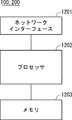
- FIG. 17 is a block diagram showing a configuration example of the video analysis units 100 and 200 (hereinafter referred to as the video analysis unit 100 and the like).
- the video analysis unit 100 and the like include a network interface 1201, a processor 1202, and a memory 1203.
- the network interface 1201 is used to communicate with other network node devices that make up the communication system.
- Network interface 1201 may be used to perform wireless communication.
- the network interface 1201 may be used to perform wireless LAN communication specified in the IEEE 802.11 series or mobile communication specified in 3GPP (3rd Generation Partnership Project).
- the network interface 1201 may include, for example, an IEEE802.3 series compliant network interface card (NIC).
- NIC network interface card
- the processor 1202 reads the software (computer program) from the memory 1203 and executes it to perform the processing of the monitoring device 10 or the like described by using the flowchart or the sequence in the above-described embodiment.
- the processor 1202 may be, for example, a microprocessor, an MPU (Micro Processing Unit), or a CPU (Central Processing Unit).
- Processor 1202 may include a plurality of processors.
- Memory 1203 is composed of a combination of volatile memory and non-volatile memory. Memory 1203 may include storage located away from processor 1202. In this case, processor 1202 may access memory 1203 via an I / O interface (not shown).
- the memory 1203 is used to store the software module group. By reading these software modules from the memory 1203 and executing the processor 1202, the processor 1202 can perform the processing of the video analysis unit 100 and the like described in the above-described embodiment.
- each of the processors included in the video analysis unit 100 and the like executes one or a plurality of programs including a group of instructions for causing the computer to perform the algorithm described with reference to the drawings. ..
- FIGS. 2, 4, 11, 12 and 13 show the specific order of execution, but the order of execution may be different from the drawn form. For example, the order of execution of two or more steps may be swapped with respect to the indicated order. Also, the two or more steps shown consecutively in FIGS. 2, 4, 11, 12 and 13 may be performed simultaneously or partially simultaneously. Further, in some embodiments, one or more steps shown in FIGS. 2, 4, 11, 12 and 13 may be skipped or omitted.
- Non-temporary computer-readable media include various types of tangible storage mediums.
- Examples of non-temporary computer-readable media include magnetic recording media (eg, flexible discs, magnetic tapes, hard disk drives), magneto-optical recording media (eg, magneto-optical discs), CD-ROMs (Read Only Memory), CD-Rs, CD-R / W, DVD (Digital Versatile Disc), BD (Blu-ray (registered trademark) Disc), semiconductor memory (for example, mask ROM, PROM (Programmable ROM), EPROM (Erasable PROM), flash ROM, RAM (for example) RandomAccessMemory)) is included.
- magnetic recording media eg, flexible discs, magnetic tapes, hard disk drives
- magneto-optical recording media eg, magneto-optical discs
- CD-ROMs Read Only Memory
- CD-Rs Compact Only Memory
- CD-R / W Digital Versatile Disc
- DVD Digital Versatile Disc
- BD Blu-ray
- the program may also be supplied to the computer by various types of temporary computer readable medium.
- temporary computer-readable media include electrical, optical, and electromagnetic waves.
- the temporary computer-readable medium can supply the program to the computer via a wired communication path such as an electric wire and an optical fiber, or a wireless communication path.
- the present invention is not limited to the above embodiment, and can be appropriately modified without departing from the spirit.
- the first video analysis unit 100 and the second video analysis unit 200 in the video analysis device 1 may be provided in the same device, in the same server, or in the same site.
- the plurality of examples or embodiments described above can be implemented in combination as appropriate.
- (Appendix 1) An image analyzer equipped with a first image analysis unit and a second image analysis unit.
- the first video analysis unit A distribution unit that distributes at least two frames to the first video analysis unit or the second video analysis unit, A first detection unit that detects an object in a frame distributed to the first video analysis unit, and a first detection unit.
- An acquisition unit that acquires information on movement associated with the detected object and transmits the information on the movement and the detection result in the first detection unit to the second video analysis unit.
- the second video analysis unit A second detection unit that detects an object in the frame received from the distribution unit, and An adjustment unit that adjusts the detection result of the first detection unit based on the detection result of the second detection unit and information on the movement, and an adjustment unit.
- a video analyzer equipped with. (Appendix 2)
- the first video analysis unit A movement information acquisition unit that acquires information regarding movement of the detected object within the detection area, and a movement information acquisition unit.
- An analysis result transmission unit that transmits the information related to the movement and the detection result of the first detection unit to the second video analysis unit as an analysis result.
- a frame transmission unit that transmits the frames sorted when analyzed by the second video analysis unit to the second video analysis unit, and a frame transmission unit.
- the video analyzer according to Appendix 1.
- Appendix 3 The video analyzer according to Appendix 1 or 2, wherein the sorting unit sorts a series of frames to be continuously received so as to be analyzed by the second video analysis unit at a predetermined frame transmission ratio or more.
- Appendix 4 An estimation unit that estimates the bandwidth that can be used by the network from the first video analysis unit to the second video analysis unit, and an estimation unit.
- Appendix 5 The video analyzer according to Appendix 2, wherein the analysis result includes the center coordinates of a box surrounding the detected object, the width and height of the box, and an identifier indicating the detected object.
- Appendix 6 The video analysis apparatus according to any one of Appendix 1 to 5, wherein the frame assigned to the first video analysis unit is taken after the frame distributed to the second video analysis unit.
- Appendix 7 The video analyzer according to any one of Supplementary note 1 to 6, wherein the information regarding the movement includes information on the moving direction of the object or a movement vector.
- Appendix 8) A video analysis system including a first video analysis unit and a second video analysis unit.
- the first video analysis unit A distribution unit that distributes at least two frames to the first video analysis unit or the second video analysis unit, A first detection unit that detects an object in a frame distributed to the first video analysis unit, and a first detection unit.
- An acquisition unit that acquires information on movement associated with the detected object and transmits the information on the movement and the detection result in the first detection unit to the second video analysis unit.
- the second video analysis unit A second detection unit that detects an object in the frame received from the distribution unit, and An adjustment unit that adjusts the detection result of the first detection unit based on the detection result of the second detection unit and information on the movement, and an adjustment unit.
- a video analysis system equipped with. (Appendix 9)
- the first video analysis unit A movement information acquisition unit that acquires information regarding movement of the detected object within the detection area, and a movement information acquisition unit.
- An analysis result transmission unit that transmits the information related to the movement and the detection result of the first detection unit to the second video analysis unit as an analysis result.
- a frame transmission unit that transmits the frames sorted when analyzed by the second video analysis unit to the second video analysis unit, and a frame transmission unit.
- the video analysis system according to Appendix 8. (Appendix 10) The video analysis system according to Appendix 8, wherein the sorting unit sorts a series of frames to be continuously received so as to be analyzed by the second video analysis unit at a predetermined frame transmission ratio or more.
- An estimation unit that estimates the bandwidth that can be used by the network from the first video analysis unit to the second video analysis unit, and an estimation unit.
- the video analysis system according to Appendix 10 further comprising a changing unit that changes the predetermined frame transmission ratio according to the estimated usable band.
- Appendix 12 The video analysis system according to any one of Appendix 8 to 11, wherein the frame assigned to the first video analysis unit is taken after the frame distributed to the second video analysis unit.
- Appendix 13 The video analysis system according to any one of Appendix 8 to 12, wherein the first video analysis unit is provided on the edge side and the second video analysis unit is provided on the cloud side.
- Appendix 14 This is a video analysis method in which the first video analysis unit and the second video analysis unit perform video analysis in a distributed manner for a series of frames. In the first video analysis unit At least two received frames are distributed to the first video analysis unit or the second video analysis unit.
- the objects in the sorted frames are detected, and Information on the movement associated with the detected object is acquired, and the information on the movement and the detection result in the first video analysis unit are transmitted to the second video analysis unit.
- the second video analysis unit The object in the frame received from the first video analysis unit is detected, and the object is detected.
- the video analysis method according to Appendix 14 wherein a series of frames to be continuously received are sorted so as to be analyzed by the second video analysis unit at a predetermined frame transmission ratio or more.
- Appendix 19 The video analysis method according to any one of Appendix 14 to 18, wherein the frame assigned to the first video analysis unit is taken after the frame distributed to the second video analysis unit.
- Appendix 20 The video analysis method according to any one of Supplementary note 14 to 19, wherein the information regarding the movement includes information on the moving direction of the object or a movement vector.
- Video analysis system 3 Vehicle remote control system 10 Automatically driven vehicle 30 Network 50
- Remote monitoring device 100 1st video analysis unit 101b
- Video frame receiver 103
- Sorting unit 103b Frame distribution unit 104b Change unit 105 1st detection unit 105a, 105b 1st Detection unit 106
- Acquisition unit 106a Movement information acquisition unit 106b Movement vector acquisition unit 107a Analysis result transmission unit 108b
- Encoder 109a Frame transmission unit 110b
- Body control unit 200 2nd video analysis unit 201b Decoder 203b Analysis result reception unit 205 2nd detection unit 207, 207a Adjustment unit 207b Analysis result adjustment unit 212b
- Band estimation unit 250
- Vehicle control unit 260 Display unit
Landscapes
- Engineering & Computer Science (AREA)
- Multimedia (AREA)
- Physics & Mathematics (AREA)
- General Physics & Mathematics (AREA)
- Theoretical Computer Science (AREA)
- Signal Processing (AREA)
- Computer Vision & Pattern Recognition (AREA)
- Image Analysis (AREA)
- Image Processing (AREA)
Priority Applications (2)
| Application Number | Priority Date | Filing Date | Title |
|---|---|---|---|
| US17/917,616 US12579660B2 (en) | 2020-04-13 | 2021-02-19 | Video analysis apparatus, video analysis system, and video analysis method |
| JP2022515228A JP7318809B2 (ja) | 2020-04-13 | 2021-02-19 | 映像分析装置、映像分析システム及び映像分析方法 |
Applications Claiming Priority (2)
| Application Number | Priority Date | Filing Date | Title |
|---|---|---|---|
| JP2020071448 | 2020-04-13 | ||
| JP2020-071448 | 2020-04-13 |
Publications (1)
| Publication Number | Publication Date |
|---|---|
| WO2021210269A1 true WO2021210269A1 (ja) | 2021-10-21 |
Family
ID=78083871
Family Applications (1)
| Application Number | Title | Priority Date | Filing Date |
|---|---|---|---|
| PCT/JP2021/006512 Ceased WO2021210269A1 (ja) | 2020-04-13 | 2021-02-19 | 映像分析装置、映像分析システム及び映像分析方法 |
Country Status (3)
| Country | Link |
|---|---|
| US (1) | US12579660B2 (https=) |
| JP (1) | JP7318809B2 (https=) |
| WO (1) | WO2021210269A1 (https=) |
Cited By (1)
| Publication number | Priority date | Publication date | Assignee | Title |
|---|---|---|---|---|
| WO2024013936A1 (ja) * | 2022-07-14 | 2024-01-18 | 日本電気株式会社 | 映像処理システム、映像処理装置及び映像処理方法 |
Families Citing this family (1)
| Publication number | Priority date | Publication date | Assignee | Title |
|---|---|---|---|---|
| TW202526831A (zh) * | 2023-12-29 | 2025-07-01 | 財團法人工業技術研究院 | 在物件偵測模型中更新定界框或關鍵點的方法 |
Citations (2)
| Publication number | Priority date | Publication date | Assignee | Title |
|---|---|---|---|---|
| JP2010136032A (ja) * | 2008-12-04 | 2010-06-17 | Hitachi Ltd | 映像監視システム |
| WO2018012084A1 (ja) * | 2016-07-15 | 2018-01-18 | パナソニックIpマネジメント株式会社 | 画像認識システム |
Family Cites Families (4)
| Publication number | Priority date | Publication date | Assignee | Title |
|---|---|---|---|---|
| JP6632727B2 (ja) | 2016-07-15 | 2020-01-22 | 日立オートモティブシステムズ株式会社 | 角度計測装置 |
| US10628961B2 (en) * | 2017-10-13 | 2020-04-21 | Qualcomm Incorporated | Object tracking for neural network systems |
| JP2019118043A (ja) * | 2017-12-27 | 2019-07-18 | キヤノン株式会社 | 撮像装置、画像処理装置、制御方法およびプログラム |
| WO2020055767A1 (en) * | 2018-09-10 | 2020-03-19 | Mapbox, Inc. | Mapping objects detected in images to geographic positions |
-
2021
- 2021-02-19 US US17/917,616 patent/US12579660B2/en active Active
- 2021-02-19 JP JP2022515228A patent/JP7318809B2/ja active Active
- 2021-02-19 WO PCT/JP2021/006512 patent/WO2021210269A1/ja not_active Ceased
Patent Citations (2)
| Publication number | Priority date | Publication date | Assignee | Title |
|---|---|---|---|---|
| JP2010136032A (ja) * | 2008-12-04 | 2010-06-17 | Hitachi Ltd | 映像監視システム |
| WO2018012084A1 (ja) * | 2016-07-15 | 2018-01-18 | パナソニックIpマネジメント株式会社 | 画像認識システム |
Cited By (1)
| Publication number | Priority date | Publication date | Assignee | Title |
|---|---|---|---|---|
| WO2024013936A1 (ja) * | 2022-07-14 | 2024-01-18 | 日本電気株式会社 | 映像処理システム、映像処理装置及び映像処理方法 |
Also Published As
| Publication number | Publication date |
|---|---|
| JP7318809B2 (ja) | 2023-08-01 |
| US20230177701A1 (en) | 2023-06-08 |
| US12579660B2 (en) | 2026-03-17 |
| JPWO2021210269A1 (https=) | 2021-10-21 |
Similar Documents
| Publication | Publication Date | Title |
|---|---|---|
| US12413688B2 (en) | Transmission method, transmission system, and system control device | |
| WO2020252924A1 (zh) | 视频行人检测方法、装置、服务器及存储介质 | |
| JP7701986B2 (ja) | データ駆動型の動的に再構成された視差マップ | |
| US9781382B2 (en) | Method for determining small-object region, and method and apparatus for interpolating frame between video frames | |
| JP7310126B2 (ja) | 情報解析装置、情報解析方法、情報解析システム、及びコンピュータプログラム | |
| US20210192756A1 (en) | Partitioning and tracking object detection | |
| US9123133B1 (en) | Method and apparatus for moving object detection based on cerebellar model articulation controller network | |
| CN107613262B (zh) | 一种视觉信息处理系统与方法 | |
| JP2009147911A (ja) | 映像データ圧縮前処理方法およびこれを用いた映像データ圧縮方法と映像データ圧縮システム | |
| WO2021210269A1 (ja) | 映像分析装置、映像分析システム及び映像分析方法 | |
| CN104599512A (zh) | 一种红绿灯自动调节方法、自动调节系统及红绿灯系统 | |
| JP2016206801A (ja) | 物体検出装置、移動体機器制御システム及び物体検出用プログラム | |
| US9953235B2 (en) | Image pickup device, vehicle number image pickup device, and image pickup method | |
| US12518400B2 (en) | Information processing device, information processing system, and information processing method | |
| US12283110B2 (en) | Information processing device, information processing system, and information processing method | |
| US20220353316A1 (en) | Communication device, communication method, and non-transitory computer-readable recording medium | |
| US12155874B2 (en) | Communication control method, communication system, and transmission apparatus | |
| US9953448B2 (en) | Method and system for image processing | |
| CN113993104A (zh) | 一种数据传输方法、装置、设备及存储介质 | |
| CN116996749A (zh) | 多监控画面下的远程目标对象跟踪系统和方法 | |
| CN111325075B (zh) | 一种视频序列目标检测方法 | |
| CN114998850B (zh) | 道路拥堵信息获取方法和装置 | |
| JP7753031B2 (ja) | 解析装置および解析方法 | |
| US20210316759A1 (en) | Systems and methods to enable reciprocation in vehicular micro cloud | |
| KR102515050B1 (ko) | 터널 관제영상 보정장치 및 그 장치의 구동방법 |
Legal Events
| Date | Code | Title | Description |
|---|---|---|---|
| 121 | Ep: the epo has been informed by wipo that ep was designated in this application |
Ref document number: 21789489 Country of ref document: EP Kind code of ref document: A1 |
|
| ENP | Entry into the national phase |
Ref document number: 2022515228 Country of ref document: JP Kind code of ref document: A |
|
| NENP | Non-entry into the national phase |
Ref country code: DE |
|
| 122 | Ep: pct application non-entry in european phase |
Ref document number: 21789489 Country of ref document: EP Kind code of ref document: A1 |
|
| WWG | Wipo information: grant in national office |
Ref document number: 17917616 Country of ref document: US |