WO2021210269A1 - 映像分析装置、映像分析システム及び映像分析方法 - Google Patents
映像分析装置、映像分析システム及び映像分析方法 Download PDFInfo
- Publication number
- WO2021210269A1 WO2021210269A1 PCT/JP2021/006512 JP2021006512W WO2021210269A1 WO 2021210269 A1 WO2021210269 A1 WO 2021210269A1 JP 2021006512 W JP2021006512 W JP 2021006512W WO 2021210269 A1 WO2021210269 A1 WO 2021210269A1
- Authority
- WO
- WIPO (PCT)
- Prior art keywords
- video analysis
- unit
- video
- frame
- detection
- Prior art date
Links
- 238000004458 analytical method Methods 0.000 title claims abstract description 459
- 238000001514 detection method Methods 0.000 claims abstract description 210
- 230000005540 biological transmission Effects 0.000 claims description 61
- 239000013598 vector Substances 0.000 claims description 58
- 238000010191 image analysis Methods 0.000 claims description 30
- 238000000034 method Methods 0.000 description 27
- 238000003708 edge detection Methods 0.000 description 24
- 238000010586 diagram Methods 0.000 description 19
- 238000004891 communication Methods 0.000 description 11
- 238000012806 monitoring device Methods 0.000 description 9
- 238000012545 processing Methods 0.000 description 9
- 238000010295 mobile communication Methods 0.000 description 5
- 238000003703 image analysis method Methods 0.000 description 4
- 238000004364 calculation method Methods 0.000 description 2
- 230000000052 comparative effect Effects 0.000 description 2
- 230000003287 optical effect Effects 0.000 description 2
- 238000013459 approach Methods 0.000 description 1
- 238000004422 calculation algorithm Methods 0.000 description 1
- 238000004590 computer program Methods 0.000 description 1
- 230000007423 decrease Effects 0.000 description 1
- 238000009434 installation Methods 0.000 description 1
- 239000013307 optical fiber Substances 0.000 description 1
- 230000011218 segmentation Effects 0.000 description 1
- 239000004065 semiconductor Substances 0.000 description 1
- 239000007787 solid Substances 0.000 description 1
Images


Classifications
-
- G—PHYSICS
- G06—COMPUTING; CALCULATING OR COUNTING
- G06V—IMAGE OR VIDEO RECOGNITION OR UNDERSTANDING
- G06V20/00—Scenes; Scene-specific elements
- G06V20/50—Context or environment of the image
- G06V20/56—Context or environment of the image exterior to a vehicle by using sensors mounted on the vehicle
-
- G—PHYSICS
- G06—COMPUTING; CALCULATING OR COUNTING
- G06T—IMAGE DATA PROCESSING OR GENERATION, IN GENERAL
- G06T7/00—Image analysis
- G06T7/20—Analysis of motion
- G06T7/215—Motion-based segmentation
-
- G—PHYSICS
- G06—COMPUTING; CALCULATING OR COUNTING
- G06T—IMAGE DATA PROCESSING OR GENERATION, IN GENERAL
- G06T1/00—General purpose image data processing
- G06T1/20—Processor architectures; Processor configuration, e.g. pipelining
-
- H—ELECTRICITY
- H04—ELECTRIC COMMUNICATION TECHNIQUE
- H04N—PICTORIAL COMMUNICATION, e.g. TELEVISION
- H04N21/00—Selective content distribution, e.g. interactive television or video on demand [VOD]
- H04N21/20—Servers specifically adapted for the distribution of content, e.g. VOD servers; Operations thereof
- H04N21/23—Processing of content or additional data; Elementary server operations; Server middleware
- H04N21/234—Processing of video elementary streams, e.g. splicing of video streams or manipulating encoded video stream scene graphs
- H04N21/2343—Processing of video elementary streams, e.g. splicing of video streams or manipulating encoded video stream scene graphs involving reformatting operations of video signals for distribution or compliance with end-user requests or end-user device requirements
- H04N21/234381—Processing of video elementary streams, e.g. splicing of video streams or manipulating encoded video stream scene graphs involving reformatting operations of video signals for distribution or compliance with end-user requests or end-user device requirements by altering the temporal resolution, e.g. decreasing the frame rate by frame skipping
-
- H—ELECTRICITY
- H04—ELECTRIC COMMUNICATION TECHNIQUE
- H04N—PICTORIAL COMMUNICATION, e.g. TELEVISION
- H04N21/00—Selective content distribution, e.g. interactive television or video on demand [VOD]
- H04N21/40—Client devices specifically adapted for the reception of or interaction with content, e.g. set-top-box [STB]; Operations thereof
- H04N21/43—Processing of content or additional data, e.g. demultiplexing additional data from a digital video stream; Elementary client operations, e.g. monitoring of home network or synchronising decoder's clock; Client middleware
- H04N21/44—Processing of video elementary streams, e.g. splicing a video clip retrieved from local storage with an incoming video stream or rendering scenes according to encoded video stream scene graphs
- H04N21/44008—Processing of video elementary streams, e.g. splicing a video clip retrieved from local storage with an incoming video stream or rendering scenes according to encoded video stream scene graphs involving operations for analysing video streams, e.g. detecting features or characteristics in the video stream
-
- G—PHYSICS
- G06—COMPUTING; CALCULATING OR COUNTING
- G06T—IMAGE DATA PROCESSING OR GENERATION, IN GENERAL
- G06T2210/00—Indexing scheme for image generation or computer graphics
- G06T2210/12—Bounding box
-
- H—ELECTRICITY
- H04—ELECTRIC COMMUNICATION TECHNIQUE
- H04N—PICTORIAL COMMUNICATION, e.g. TELEVISION
- H04N7/00—Television systems
- H04N7/18—Closed-circuit television [CCTV] systems, i.e. systems in which the video signal is not broadcast
Definitions
- the present invention relates to a video analyzer, a video analysis system, and a video analysis method.
- Non-Patent Document 1 discloses a technique for performing video analysis in a distributed manner by a plurality of video analysis units for a series of video frames.
- Non-Patent Document 1 still has a problem that the accuracy of video analysis is not sufficient.
- the present invention has been made to solve such a problem, and an object of the present invention is to provide an image analysis device, an image analysis system, and an image analysis method having improved image analysis accuracy.
- the video analyzer is An image analyzer equipped with a first image analysis unit and a second image analysis unit.
- the first video analysis unit A distribution unit that distributes at least two frames to the first video analysis unit or the second video analysis unit, A first detection unit that detects an object in a frame distributed to the first video analysis unit, and a first detection unit.
- An acquisition unit that acquires information on movement associated with the detected object and transmits the information on the movement and the detection result in the first detection unit to the second video analysis unit.
- the second video analysis unit A second detection unit that detects an object in the frame received from the distribution unit, and An adjustment unit that adjusts the detection result of the first detection unit based on the detection result of the second detection unit and information on the movement, and an adjustment unit. To be equipped.
- the video analysis system is A video analysis system including a first video analysis unit and a second video analysis unit.
- the first video analysis unit A distribution unit that distributes at least two frames to the first video analysis unit or the second video analysis unit, A first detection unit that detects an object in a frame distributed to the first video analysis unit, and a first detection unit.
- An acquisition unit that acquires information on movement associated with the detected object and transmits the information on the movement and the detection result in the first detection unit to the second video analysis unit.
- the second video analysis unit A second detection unit that detects an object in the frame received from the distribution unit, and An adjustment unit that adjusts the detection result of the first detection unit based on the detection result of the second detection unit and information on the movement, and an adjustment unit. To be equipped.
- the video analysis method is This is a video analysis method in which the first video analysis unit and the second video analysis unit perform video analysis in a distributed manner for a series of frames.
- the first video analysis unit At least two frames are received in succession, and it is determined whether to analyze by the first video analysis unit or the second video analysis unit.
- the objects in the sorted frames are detected, and Information on the movement associated with the detected object is acquired, and the information on the movement and the detection result in the first video analysis unit are transmitted to the second video analysis unit.
- the object in the frame received from the first video analysis unit is detected, and the object is detected.
- the detection result in the first video analysis unit is adjusted based on the detection result in the second video analysis unit and the information regarding the movement.
- an image analysis device it is possible to provide an image analysis device, an image analysis system, and an image analysis method with improved image analysis accuracy.
- FIG. 5 is a diagram showing a video frame including an exemplary object detected by the first video analysis unit according to the third embodiment. It is a figure explaining the example of calculating the movement vector which concerns on Embodiment 3.
- FIG. 5 is a diagram showing a video frame including an exemplary object detected by the first video analysis unit according to the third embodiment. It is a figure explaining the example of calculating the movement vector which concerns on Embodiment 3.
- FIG. 5 is a diagram showing a frame including an exemplary object detected by the second video analysis unit according to the third embodiment. It is a conceptual diagram explaining the whole picture of the adjustment process which concerns on some Embodiments. It is a conceptual diagram explaining the specific example of the adjustment process which concerns on some Embodiments. It is a flowchart which shows the operation of the 1st video analysis part arranged on the edge side which concerns on Embodiment 3.
- FIG. FIG. 5 is a flowchart showing an operation related to video frame reception of the second video analysis unit arranged on the cloud side according to the third embodiment. It is a flowchart which shows the operation by the analysis result adjustment part arranged on the cloud side which concerns on Embodiment 3.
- FIG. It is a block diagram which shows the structural example of the hardware of the image analyzer or the image analysis part.
- FIG. 1 is a block diagram showing a configuration of a video analyzer according to the first embodiment.
- the video analysis device 1 includes a first video analysis unit 100 and a second video analysis unit 200 in order to disperse and process at least two frames.
- the video analyzer 1 can be implemented by one or more computers. At least two frames may be two consecutive frames or two frames sandwiching another frame.
- the first video analysis unit 100 has a distribution unit 103 that distributes at least two frames to the first image analysis unit 100 or the second image analysis unit 200, and a frame that is distributed when analyzed by the first video analysis unit 100.
- the first detection unit 105 that detects the object and the information about the movement associated with the detected object are acquired, and the information about the movement and the detection result by the first detection unit 105 are transmitted to the second video analysis unit 200.
- the acquisition unit 106 for transmission is provided.
- the first detection unit 105 detects a predetermined object from the frame by using a predetermined video analysis program.
- the distribution unit 103 can distribute frames to the first video analysis unit 100 or the second video analysis unit 200 at a preset distribution rate.
- the "information about the movement associated with the detected object" may include, for example, information on the moving direction of the object or a movement vector in the bounding box surrounding the object.
- the second video analysis unit 200 is a first detection unit based on the second detection unit 205 that detects an object in the frame from the distribution unit 103, the detection result of the second detection unit 205, and the information related to the movement.
- An adjusting unit 207 for adjusting the detection result in 105 is provided.
- the second detection unit 205 detects a predetermined object from the frame by using a predetermined video analysis program.
- FIG. 2 is a flowchart showing the video analysis method according to the first embodiment.
- the video analysis method according to the first embodiment at least two frames are distributed and processed by the first video analysis unit 100 and the second video analysis unit 200.
- the first video analysis unit 100 At least two frames received in succession are distributed to the first video analysis unit 100 or the second video analysis unit 200 (step S101).
- An object in the frame distributed to the first video analysis unit 100 is detected (step S102).
- Information on the movement associated with the detected object is acquired, and the information on the movement and the detection result in the first video analysis unit 100 are transmitted to the second video analysis unit 200 (step S103).
- the second video analysis unit 200 detects an object in the frame received from the first video analysis unit 100 (step S103).
- the second video analysis unit 200 adjusts the detection result of the first video analysis unit 100 based on the detection result of the second video analysis unit 200 and the information regarding the movement (step S105).
- FIG. 3 is a block diagram showing a configuration of the video analyzer according to the second embodiment.
- the video analysis device 1 includes a first video analysis unit 100a and a second video analysis unit 200a in order to disperse and process a series of frames (including at least two frames).
- the first video analysis unit 100a distributes at least two series of frames received from the camera to the first video analysis unit 100a, the second video analysis unit 200a, the distribution unit 103a, and the first video analysis unit 100.
- the first detection unit 105a that detects the object in the frame, the movement information acquisition unit 106a that acquires the information about the movement in the detected object, the information about the movement, and the detection result by the first detection unit 105a are the first.
- the analysis result transmission unit 107a for transmitting to the two video analysis units and the frame transmission unit 109a for transmitting the frames distributed to the second video analysis unit 200a to the second video analysis unit 200a are provided.
- the first detection unit 105a detects a predetermined object from the frame by using a predetermined video analysis program.
- the detected object can be surrounded by a bounding box.
- the movement information acquisition unit 106a recognizes that the object is moving between the two frames, and acquires the movement information about the object in the bounding box.
- the movement information acquisition unit 106a compares the video frame temporarily stored in the storage unit in the first video analysis unit 100a with the detection result frame from the first detection unit 105a to acquire the movement information. Can be done.
- the acquired movement information may include information on the moving direction of the object or a movement vector.
- the distribution unit 103 can distribute frames to the first video analysis unit 100 or the second video analysis unit 200 at a preset distribution rate.
- the distribution unit 103 when the distribution rate is set to 10%, the distribution unit 103 counts consecutively received frames using the distribution counter, transmits the first frame to the second video analysis unit 200, and then the rest. The nine frames can be distributed to the first video analysis unit 100.
- the distribution rate is set to be equal to or higher than the threshold value.
- the "information regarding the movement of the detected object in the detection area" may include, for example, information on the moving direction of the object in the bounding box surrounding the object or a movement vector.
- the frame transmission unit 109a may include an encoder that encodes a video frame with a predetermined quality.
- the first video analysis unit 100a includes an analysis result transmission unit 107a and a frame transmission unit 109a.
- the analysis result transmission unit 107a transmits the movement vector for the frame distributed to the first video analysis unit 100a and the detection result as the analysis result to the second video analysis unit 200a. Therefore, the transmission data capacity per frame of the analysis result transmission unit 107a is relatively small.
- the frame transmission unit 109a encodes and transmits the frames distributed to the second video analysis unit 200a with a predetermined quality, the transmission data capacity per frame of the frame transmission unit 109a is determined by the analysis result transmission unit 107a. growing.
- the analysis result transmission unit 107a and the frame transmission unit 109a are different frames, that is, the frame distributed to the first video analysis unit 100a in the distribution unit 103a and the second video analysis unit. It deals with the frames allocated to 200a.
- the second video analysis unit 200a performs the first detection based on the second detection unit 205a that detects the object in the frame received from the frame transmission unit 109a and the detection result and the information on the movement by the second detection unit 205a.
- An adjusting unit 207a for adjusting the detection result of the unit 105a is provided.
- the second detection unit 205a detects a predetermined object from the frame by using a predetermined video analysis program different from or more accurate than the video analysis program of the first detection unit 105a.
- FIG. 4 is a flowchart showing the video analysis method according to the second embodiment.
- the video analysis method according to the second embodiment at least two frames are distributed and processed by the first video analysis unit 100 and the second video analysis unit 200.
- the first video analysis unit 100a separately distributes a series of frames received from the camera to the first video analysis unit 100a or the second video analysis unit 200a (step S201).
- the first video analysis unit 100a detects an object in the frame distributed to the first video analysis unit 100a (step S202).
- the first video analysis unit 100a acquires information regarding the movement of the detected object in the detection area (for example, the bounding box) (step S203).
- the first video analysis unit 100a transmits information on movement and the detection result of the first video analysis unit 100a to the second video analysis unit 200a (step S204).
- the first video analysis unit 100a transmits the frames allocated to the second video analysis unit 200a to the second video analysis unit 200a (step S205).
- the second video analysis unit 200a detects an object in the frame received from the first video analysis unit 100a (step S206).
- the detection result in the first video analysis unit 100a is adjusted based on the detection result in the second video analysis unit 200a and the information regarding the movement received from the first video analysis unit 100a (step S207).
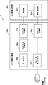
- FIG. 5 is a block diagram showing the structure of the video analysis system according to the third embodiment.
- the video analysis system 1b includes a first video analysis unit 100b and a second video analysis unit 200b.
- the first video analysis unit 100b is arranged on the edge side and is connected to the camera by wire or wirelessly.
- wireless communication such as Wi-Fi (registered trademark)
- the number of connections is small, so that the communication is stable as compared with the mobile phone network such as 4G and 5G. Is possible.
- the first video analysis unit 100b cannot prepare sufficient calculation resources due to restrictions on the power supply and installation space, and often becomes a low-precision model with low calculation cost.
- the second video analysis unit 200 is connected to the first video analysis unit 100 via a wireless network such as LTE (registered trademark), 5G, or Wi-fi (registered trademark), and is compared with the first video analysis unit 100b.
- LTE registered trademark
- 5G Fifth Generation
- Wi-fi registered trademark
- the first video analysis unit 100b is, for example, an in-vehicle video analysis device that can be realized by a computer.
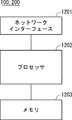
- the first video analysis unit 100b is, for example, a ROM (Read Only) in which a processor 1202 such as a CPU (Central Processing Unit) that performs arithmetic processing and the like, an arithmetic program executed by the processor 1202, and the like are stored. It is composed of a memory 1203 composed of a memory) and a RAM (RandomAccessMemory), a microcomputer composed of an interface unit (I / F) 1201 for inputting / outputting signals to and from the outside, and the like.
- a ROM Read Only
- a processor 1202 such as a CPU (Central Processing Unit) that performs arithmetic processing and the like, an arithmetic program executed by the processor 1202, and the like are stored.
- It is composed of a memory 1203 composed of a memory) and a RAM (RandomAccessMemory),
- the processor 1202, the memory 1203, and the interface unit 1201 are connected to each other via a data bus or the like.
- the interface unit (I / F) 1201 may be used to perform wireless LAN communication specified in the IEEE 802.11 series or mobile communication specified in 3GPP (3rd Generation Partnership Project).
- the interface unit (I / F) 1201 may include, for example, a network interface card (NIC) compliant with the IEEE802.3 series.
- NIC network interface card
- the first video analysis unit 100b includes a video frame reception unit 101b, a frame distribution unit 103b, a change unit 104b, a first detection unit 105b, a movement vector acquisition unit 106b, an analysis result transmission unit 107b, and an encoder 108b. And the storage unit 110b.
- the video frame receiving unit 101b continuously receives one or more video frames from an in-vehicle camera (not shown) via a wired network.
- an in-vehicle camera will be described as an example, but another camera such as a fixed camera may be used.
- Each received video frame is temporarily stored in the storage unit 110b.
- the frame distribution unit 103b determines whether each video frame from the video frame reception unit 101b is analyzed by the first video analysis unit 100b or the second video analysis unit 200b by a predetermined frame transmission ratio (also known as the distribution rate). (Sometimes called). For example, when the predetermined frame transmission ratio is set to 10%, out of 10 continuously received video frames, 9 frames are transmitted after transmitting 1 frame to the 2nd video analysis unit 200b. Allocate to the first video analysis unit 100b.
- the frame distribution unit 103b distributes continuously received video frames at a predetermined frame transmission ratio or more so that the second video analysis unit 200b analyzes them.
- the predetermined frame transmission ratio can be set based on the available band of the wireless network from the first video analysis unit 100b to the second video analysis unit 200b.
- the frame distribution unit 103b estimates a usable band indicating a band that can be used for transmitting data on the wireless network. For example, the frame distribution unit 103b may evaluate the usable band by a level-divided value (for example, large, medium, small), and change the frame transmission ratio step by step based on the evaluated usable band (details). Will be described later).
- a level-divided value for example, large, medium, small
- the encoder 108b When the encoder 108b receives the video frame sorted so as to be analyzed by the second video analysis unit 200b from the frame sorting unit 103b, the encoder 108b encodes the video frame with a predetermined quality and analyzes the encoded video frame in the second video analysis. It is transmitted to the unit 200b.
- the video frame distributed by the frame distribution unit 103b so as to be analyzed by the first video analysis unit 100b is sent to the first detection unit 105b.
- the first detection unit 105b detects an object in the sorted frame. Specifically, the first detection unit 105b uses the image analysis program A (sometimes also referred to as an edge model, a lightweight model, or a low-precision model) with respect to the image frame distributed by the frame distribution unit 103b. Perform image analysis.
- FIG. 6 is a diagram showing a video frame including an exemplary object detected by the first video analysis unit.
- An example of a lightweight model is YOLOv3 Tiny, which has slightly inferior recognition accuracy but can operate at high speed.
- FIG. 6 shows an exemplary video frame in which an in-vehicle camera of a moving vehicle captures the front.
- traffic-related objects such as automobiles, trucks, buses, motorcycles, bicycles, pedestrians, and traffic lights are detected.
- each detected object is surrounded by a bounding box.
- the notation "Car: 3%" shown in the vicinity of the bounding box indicates that the probability (reliability) that the detection target is an automobile is 3%.
- objects related to traffic about 1 to 200 objects can be detected per frame.
- the movement vector acquisition unit 106b acquires the movement vector in the object detected by the first detection unit 105b between the two frames. That is, the movement vector acquisition unit 106b can acquire the movement vector by comparing the luminance gradient between the detection result frame from the first detection unit 105b and the frame stored in the storage unit 110b.
- FIG. 7 is a diagram illustrating an example of calculating a movement vector.
- FIG. 7A shows a detected vehicle in a video frame taken at time t.
- the movement vector acquisition unit 106b acquires the average value of the movement vectors in the bounding box shown by the broken line. This movement vector can be used to calculate how much the two frames are and adjust the detection position.
- the two frames may be two consecutive frames in chronological order (for example, t-1, t) or two frames separated by a predetermined time (for example, t-5, t).
- the movement vector is obtained by using the Gunnar Farneback method for Optical Flow. That is, first, movement vectors in the x-direction and the y-direction are generated per pixel in the entire frame. After that, the average vector in the detection area (for example, the bounding box) of each edge object is calculated. As a result, it is possible to recognize in which direction each detection object is moving between frames.
- FIG. 7B shows a shifted automobile based on the movement vector acquired by the adjustment unit 207b (that is, FIG. 7B shows an estimated video frame at time t + 1).
- the solid bounding box indicates the bounding box after the shift.
- the object can be moved for a predetermined time based on the movement vector.
- the data capacity can be significantly reduced by focusing only on the movement vector associated with the detected object or the bounding box instead of the movement vector of the entire two frames in this way.
- the analysis result transmission unit 107b transmits the object detected by the first detection unit 105 and the movement vector acquired by the movement vector acquisition unit 106 to the second video analysis unit 200b via the wireless network as the analysis result. do.
- the analysis result may include, for example, the center coordinates (x, y) of the bounding box, the width, the height, the identifier of the detected object, the number of detected objects, and the movement vector (x, y). That is, the analysis result transmission unit 107b transmits such an analysis result to the second video analysis unit 200b instead of the video frame itself analyzed by the first video analysis unit 100b.
- the transmission data capacity is reduced and the occurrence of problems (block noise, frame dropping, etc.) due to insufficient bandwidth is suppressed as compared with the case where the video frame itself analyzed by the first video analysis unit 100b is transmitted.
- the second video analysis unit 200b is, for example, a cloud server that can be realized by a computer.
- the second video analysis unit 200b is a ROM (Read Only) in which a processor 1202 such as a CPU (Central Processing Unit) that performs arithmetic processing and the like, an arithmetic program executed by the processor 1202, and the like are stored. It is composed of a memory 1203 composed of a memory) and a RAM (RandomAccessMemory), a microcomputer composed of an interface unit (I / F) 1201 for inputting / outputting signals to and from the outside, and the like.
- a processor 1202 such as a CPU (Central Processing Unit) that performs arithmetic processing and the like, an arithmetic program executed by the processor 1202, and the like are stored.
- It is composed of a memory 1203 composed of a memory) and a RAM (RandomAccessMemory), a microcomputer composed of an interface unit (I / F) 1201 for
- the processor 1202, the memory 1203, and the interface unit 1201 are connected to each other via a data bus or the like.
- the interface unit (I / F) may be used to perform wireless LAN communication specified in the IEEE 802.11 series or mobile communication specified in 3GPP (3rd Generation Partnership Project).
- the interface unit (I / F) 1201 may include, for example, a network interface card (NIC) compliant with the IEEE802.3 series.
- NIC network interface card
- the second video analysis unit 200b includes a decoder 201b, an analysis result receiving unit 203b, a second detection unit 205b, an analysis result adjusting unit 207b, and a band estimation unit 212b.
- the decoder 201b decodes the video frame encoded by the encoder 108b and transmits the video frame to the second detection unit 205b.
- the decoder 201b may include a frame buffer that receives video frames from the encoder 108 and temporarily stores them.
- the second detection unit 205b detects an object in the sorted frame.
- the second detection unit 205b is also called a video analysis program B (also called a cloud model or a high-precision model) capable of performing video analysis with higher accuracy than the video analysis program A for the video frame from the decoder 201. Perform image analysis in).
- An example of a high-precision model is Mask RCNN, which performs general object detection and segmentation.
- FIG. 8 is a diagram showing a video frame including an exemplary object detected by the second video analysis unit.
- FIG. 8 shows the result of detecting an object with a high-precision model in the same video frame as in FIG. In this example, as shown in FIG.
- FIG. 8 traffic-related objects such as automobiles, bicycles, pedestrians, and traffic lights are detected. Each detected object is surrounded by a bounding box.
- the notation “Car: 99%” shown in the vicinity of the bounding box indicates that the probability (reliability) that the detection target is an automobile is 99%.
- FIG. 8 shows that the object is detected with higher reliability than that of FIG.
- the analysis result receiving unit 203b receives the analysis result from the analysis result transmitting unit 107b.
- the analysis result receiving unit 203b may be an analysis result data buffer for temporarily storing the analysis result data.
- the analysis result adjustment unit 207b adjusts the video frame based on the video frame in which the object is detected by the second detection unit 205b (the object is surrounded by a bounding box) and the movement vector. Specifically, the analysis result adjusting unit 207b adjusts the video frame shot after the video frame based on the video frame in which the object is detected by the second detection unit 205b and the movement vector. The analysis result adjustment unit 207b is detected by the first detection unit 105b based on, for example, a video frame in which the object is detected by the second detection unit 205b (the object is surrounded by a bounding box) and a movement vector. From the result, adjust the position of the object.
- the analysis result adjusting unit 207b adjusts the detection result of the low-precision model by the first detection unit 105b with reference to the detection result of the high-precision model of the second detection unit 205b.
- the analysis result adjustment unit 207b refers to the video frame detected by the high-precision model of the second detection unit 205b, and the video image taken after the video frame and distributed to the first detection unit 105 (low-precision model). Estimate the frame with high accuracy.
- the band estimation unit 212b can be used to transmit data via a wireless network from the first video analysis unit 100b to the second video analysis unit 200b with reference to the usage amount of the analysis result data buffer and the frame buffer described above. Estimate the usable band that indicates a certain band. The band estimation unit 212b notifies the change unit 104 of the first video analysis unit 100b of the estimated usable band (for example, large, medium, small).
- the change unit 104b changes the frame transmission ratio of the frame distribution unit 103b based on the estimated usable band. For example, when the usable band is large, the changing unit 104b may change the frame transmission ratio to a high value to increase the analysis ratio in the cloud. Alternatively, when the usable band is small, the changing unit 104b may change the frame transmission ratio to a low value and increase the analysis ratio at the edge.
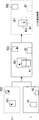
- FIG. 9 is a conceptual diagram illustrating an overall picture of the adjustment process according to some embodiments.
- the frame shown by the solid line indicates the frame sent to the cloud.
- the frame shown by the broken line indicates the frame distributed to the edge.
- the frame distribution unit 103b transmits frames to the second video analysis unit 200 on the cloud side at a frame transmission rate of 25%. That is, the frame (shown by the solid line) taken at time t is sent to the second video analysis unit 200b on the cloud side.
- the object is detected by the high-precision model of the second detection unit 205b on the cloud side.
- a frame in which an object is detected on the cloud side is called a reference frame.
- the object is detected by the first detection unit 105 of the first video analysis unit 100b on the edge side. Further, for the frame photographed at the time t + 1, the movement vector in the bounding box surrounding the detection target is acquired by the movement vector acquisition unit 106b.
- These detection results also referred to as edge detection results in the present specification
- movement vectors are sent by the analysis result transmission unit 107b to the analysis result reception unit 203b of the second video analysis unit 200b.
- the analysis result adjusting unit 207b sets the time based on the detection result (also referred to as the cloud detection result in the present specification) by the second detection unit 205b on the cloud side for the frame at time t and the movement vector for the frame at time t + 1. Adjust the edge detection result for the t + 1 frame.
- the object is detected by the first detection unit 105b of the first video analysis unit 100b on the edge side.
- the movement vector acquisition unit 106b acquires the movement vector in the bounding box surrounding the detection target.
- These edge detection results and movement vectors are sent by the analysis result transmission unit 107b to the analysis result receiving unit 203b of the second video analysis unit 200b.
- the analysis result adjusting unit 207b adjusts the edge detection result for the frame at time t + 2 based on the adjusted result for the frame at time t + 1 and the movement vector for the frame at time t + 2.
- the object is detected by the first detection unit 105b of the first video analysis unit 100b on the edge side.
- the movement vector acquisition unit 106b acquires the movement vector in the bounding box surrounding the detection target.
- These edge detection results and movement vectors are sent by the analysis result transmission unit 107b to the analysis result receiving unit 203b of the second video analysis unit 200b.
- the analysis result adjustment unit 207b adjusts the edge detection result for the frame at time t + 3 based on the adjusted result for the frame at time t + 2 and the movement vector for the frame at time t + 3.
- the frame shot at time t + 4 is sent to the second video analysis unit 200b on the cloud side again by the frame distribution unit 103. Then, in the frame, the object is detected by the high-precision model of the second detection unit 205b on the cloud side. That is, the frame taken at the time t + 4 becomes the reference frame, and the adjustment process after the time t + 5 is performed.
- the frame transmission ratio is set to 25%, but the present invention is not limited to this.
- the shooting interval between frames can be set arbitrarily.
- the adjusted result of the immediately preceding t + 1 or t + 2 frame is used as a reference, but the reference frame may be used as a reference. That is, the edge detection result for the frame at time t + 2 may be adjusted based on the cloud detection result for the frame at time t and the movement vector for the frame at time t + 2 with reference to the reference frame at time t. Similarly, the edge detection result for the frame at time t + 3 may be adjusted based on the cloud detection result for the frame at time t and the movement vector for the frame at time t + 3 with reference to the reference frame at time t. ..
- FIG. 10 is a conceptual diagram illustrating a specific example of the operation of the analysis result adjusting unit 207b.
- the analysis result adjustment unit 207b of the second video analysis unit 200b on the cloud side uses the cloud detection result for the frame captured at time t, the edge detection result for the frame captured at time t + 1, and the movement vector at time t + 1. Estimate the exact result in.
- the frame shot at time t is detected by the second detection unit 205b of the second video analysis unit 200b on the cloud side.
- the frame shows two bounding boxes B1 and B2 (also referred to as cloud detection objects) surrounding the two detected objects.
- the object is detected by the first detection unit 105b of the first video analysis unit 100 on the edge side.
- two bounding boxes B21 and B22 also referred to as edge detection objects surrounding the two detected objects are shown in the frame.
- the frame itself is not sent to the second video analysis unit 200b on the cloud side, and the detection result of the object (bounding boxes B21, B22) and the average value of the movement vectors in each bounding are the second video. It is sent to the analysis unit 200b.
- the analysis result adjustment unit 207b arranges the bounding boxes B21 and B22 photographed at time t + 1 on the reference frame photographed at time t.
- the bounding box B1 is moved to the bounding box B12 based on the average moving vector in the bounding box B11 by the shooting interval between these frames (in FIG. 9, the cloud object after the movement).
- the bounding box B2 in the frame at time t no object is detected in the frame at time t + 1 (that is, there is no bounding box overlapping with the bounding box B2 in the frame at time t + 1). That is, it is considered that the object in the bounding box B2 in the frame at time t is framed out by the movement of the object in the frame at time t + 1. Therefore, the bounding box B2 is deleted from the estimation result at time t + 1.
- the bounding box B22 in the frame at time t + 1 no object is detected in the frame at time t (that is, there is no bounding box that overlaps with the bounding box B22 in the frame at time t).
- the object in the bounding box B22 in the frame at time t + 1 is considered to have newly appeared (in FIG. 9, the edge new detection object). Therefore, the bounding box B22 is kept in the estimation result at time t + 1.
- the analysis result adjustment unit 207b on the cloud side adjusts the edge detection result at time t + 1, and as shown in FIG. 10, a more accurate analysis result at time t + 1 (adjusted result in FIG. 9). Can be estimated.
- the analysis result at the estimated time t + 1 (the adjusted result of t + 1 in FIG. 9) is referred to in the frame adjustment process at time t + 2 (see FIG. 9).
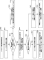
- FIG. 11 is a flowchart showing the operation of the first video analysis unit arranged on the edge side according to the third embodiment.
- the first video analysis unit 100b first initializes (step S301). Here, the frame distribution counter and the like are initialized.
- the video frame receiving unit 101b receives a video frame from an in-vehicle camera (not shown) (step S302).
- the frame distribution unit 103b distributes whether the video frame is analyzed by the second video analysis unit 200b on the cloud side or the first detection unit 105b on the edge side (step S303).
- the encoder 108b encodes the video frame with a predetermined quality and transmits it to the second video analysis unit 200 (step).
- step S304 the encoder 108b encodes the video frame with a predetermined quality and transmits it to the second video analysis unit 200 (step).
- the first detection unit 105b uses the edge model (lightweight model) to display the object in the video frame. Is detected (step S305). Subsequently, the moving vector acquisition unit 106 acquires the average moving vector in the bounding box surrounding the detected object (step S306). The analysis result transmission unit 107b transmits the detection result of each object and the movement vector of each object to the second video analysis unit 200b (step S307). Subsequently, when the video frame receiving unit 101b receives the subsequent frames from the camera in chronological order (returning to step S302), the above process is repeated.
- the edge model lightweight model
- FIG. 12 is a flowchart showing an operation related to video frame reception of the second video analysis unit arranged on the cloud side according to the third embodiment.
- the second video analysis unit 200b receives the video frame (step S401).
- the decoder 201 decodes the encoded video frame.
- the second detection unit 205 detects an object in the video frame using the cloud model (step S402). Initialize the cloud detection object (step S403).
- the undetected counter value and the position of the cloud-detected object which will be described later, are initialized.
- the second detection unit 205b of the second video analysis unit 200 outputs the cloud detection result to the external and analysis result adjustment units 207b (step S404).
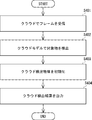
- FIG. 13 is a flowchart showing the operation of the analysis result adjusting unit arranged on the cloud side according to the third embodiment.
- the analysis result adjusting unit 207b receives the cloud detection result from the second detection unit 205b for the frame captured at the time t and holds it as a reference frame (step S410).
- the analysis result adjusting unit 207b receives the edge analysis result for the frame at time t + 1 taken immediately after the reference frame taken at time t from the analysis result receiving unit 203b (step S411).
- the analysis result includes the detection result by the first detection unit 105b and the movement vector of each detected object acquired by the movement vector acquisition unit 106b.
- the capacity of this analysis result data is significantly smaller than the capacity of the video frame itself.
- the analysis result adjustment unit 207b acquires the one with the largest overlap between the cloud detection target and the edge detection target. (Step S414).
- the bounding box B1 surrounding the cloud detection target and the bounding box B21 surrounding the edge detection target have the largest overlap, they are acquired.
- step S416 it is determined whether the multiplicity is equal to or higher than the threshold value.
- the degree of duplication is evaluated by IoU (Intersection over Union).
- the acquired edge detection object is deleted (step S417), and the acquired cloud detection object is moved according to the movement vector of the edge detection object (step). S419).
- the edge detection result may have low accuracy. Therefore, the bounding box B21 surrounding the edge detection target is deleted. .. Further, the bounding box B1 surrounding the cloud detection target is moved to the bounding box B12 according to the average moving vector in the bounding box B21. In this way, a highly accurate estimation result at t + 1 can be obtained.
- step S412 the process returns to step S412, and other cloud detection objects in the reference frame are also examined. That is, when the unadjusted cloud detection target is in the reference frame (YES in step S412), the one with the largest overlap between the cloud detection target and the edge detection target is acquired (step S414). In the example of FIG. 11, only the bounding box B2 surrounding the cloud detection target is acquired (because there is no overlapping edge detection target).
- the overlap degree is less than the threshold value (NO in step S417), and the cloud detection object in the reference frame is taken at the time t + 1 immediately after. If it is not detected within the frame of, the undetected counter of the cloud detection target is added (step S421). If the undetected counter is larger than the threshold number (that is, the cloud detection target is not found in a predetermined number of consecutive frames), the cloud detection target is considered to have been framed out due to its movement, and is therefore deleted. In the example of FIG. 10, the bounding box B2 surrounding the cloud detection target is deleted.
- the analysis result adjustment unit 207b sets the cloud detection object and the newly appearing edge detection object at time t + 1. It is output as an estimation result (step S413).
- the newly appearing edge detection object is the bounding box B22.
- a specific example of the estimation result is shown in FIG.
- FIG. 14 is a graph illustrating the detection accuracy of a video analysis system using a fixed camera.
- the vertical axis indicates the detection accuracy of the object
- the horizontal axis indicates the frame transmission ratio indicating the distribution rate between the edge and the frame.
- 10 -1 on the horizontal axis sends a frame to the second video analysis unit 200b on the cloud side at a rate of once in 10 times out of consecutive frames, in other words, one frame is sent to the cloud side second frame. 2
- the first image analysis unit 100 on the edge side processes the image 9 times in a row.
- the related method 1 is the detection accuracy when the cloud detection result for the frame shot at time t is used as the detection result for the frame shot at time t + 1.
- the related method 2 is the detection accuracy when the edge detection result of the frame taken at the time t + 1 is used as it is.
- FIG. 15 is a graph illustrating the detection accuracy of a video analysis system using an in-vehicle camera. Since FIG. 15 is basically the same as FIG. 14, description thereof will be omitted as appropriate. From FIG. 15, it can be seen that when an in-vehicle camera is used, the proposed method is considerably more accurate than the related method 1 and significantly higher than the related method 2. In particular, when an in-vehicle camera is used, the camera itself moves, so that the detection position shifts significantly between the frames. Therefore, in the related method 2 in which the cloud detection result for the immediately preceding frame is used as it is, the accuracy is significantly lowered. Further, from FIG.
- the accuracy of the proposed method deteriorates to the same extent as that of the related method 3 as the frame transmission ratio decreases. From this, also in the present proposed method, if the frame transmission ratio is equal to or more than the threshold value (for example, 1% or more in FIG. 15), more accurate video analysis than the related method can be realized.
- the threshold value for example, 1% or more in FIG. 15
- the video analysis system 1 refers to the cloud detection result and adjusts the edge detection result to perform high-precision video analysis even if the wireless network has a low band. Can be realized. Further, even when the accuracy difference of the image detection between the edge model and the cloud model is large, it is possible to realize highly accurate image analysis for a series of image frames. Further, even when a camera such as an in-vehicle camera moves, high-precision video analysis can be realized.
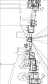
- FIG. 16 is a block diagram showing a configuration of the vehicle remote control system according to the fourth embodiment.
- the vehicle remote control system 3 includes a plurality of autonomous driving vehicles 10A and 10B, and a remote monitoring device 50 that monitors and controls these autonomous driving vehicles 10A and 10B.
- the plurality of autonomous driving vehicles 10A are connected to the remote monitoring device 50 via a network 30 such as a mobile phone network.
- a network 30 such as a mobile phone network.
- the usable band may fluctuate, so that the image quality of the remote monitoring device 50 may deteriorate due to the lack of band.
- FIG. 16 shows two self-driving vehicles, the number of vehicles is not limited to this. It may be equipped with N self-driving vehicles (natural numbers of N or more).
- Examples of the network 30 referred to here include a local area network (LAN) and a wide area network (WAN), for example, the Internet.
- Communication networks include, for example, Ethernet (registered trademark), Universal Serial Bus (USB), FIREWIRE (registered trademark), and global system for mobile communication (Global System for Mobile Communications, GSM (registered trademark)).
- GSM Global System for Mobile Communications
- GSM registered trademark
- Enhanced Data GSM® Environment Enhanced Data GSM® Environment, EDGE
- CDMA Code Division Multiple Access
- TDMA Time Division Multiple Access
- Bluetooth Various wired or wireless applications such as Registered Trademarks
- Wi-Fi® voice over Internet Protocol
- VoIP Wi-MAX®
- Wi-MAX® or any other suitable communication protocol. It can be implemented using any well-known network protocol, including protocols.
- each autonomous driving vehicle includes one or more in-vehicle cameras 130, a first video analysis unit 100, and a vehicle body control unit 150. Since the specific configuration of the first video analysis unit 100 (100a, 100b) is basically the same as the configuration described above, it is omitted here.
- the first video analysis unit 100 distributes the video frame from the vehicle-mounted camera 130 to the first video analysis unit 100 or the second video analysis unit 200.
- the first video analysis unit 100 encodes the frames distributed to the second video analysis unit 200 and transmits the frames to the second video analysis unit 200 via the wireless network. Further, the first video analysis unit 100 detects an object in the frame distributed to the first video analysis unit 100 with an edge model.
- the first video analysis unit 100 acquires a movement vector in the detection region of the object.
- the first video analysis unit 100 transmits each object (detection result) and a movement vector associated with the object (detection result) to the remote monitoring device 50 via the wireless network.
- the remote monitoring device 50 remotely monitors and controls each autonomous driving vehicle by using the image received from the in-vehicle camera of each autonomous driving vehicle.
- the remote driver may remotely drive a specific self-driving vehicle while looking at the display unit 260 displaying the image from each in-vehicle camera.
- the remote monitoring device 50 may automatically control each autonomous driving vehicle based on the result of video analysis with high accuracy.
- the remote monitoring device 50 includes a display unit 260, a second video analysis unit 200 (200a, 200b), and a vehicle control unit 250. Since the specific configuration of the second video analysis unit 200 (200a, 200b) is basically the same as the configuration described above, it is omitted here.
- the second video analysis unit 200 detects an object in the video frame sent from each autonomous driving vehicle by using a cloud model. Further, as described above, the second video analysis unit 200 adjusts the analysis result sent from the first video analysis unit 100 of each autonomous driving vehicle. As a result, the second video analysis unit 200 can obtain not only a highly accurate detection result for the video frame sent from each autonomous driving vehicle but also a highly accurate estimation result for the subsequent video frame.
- the display unit 260 displays the analysis result analyzed by the second video analysis unit 200. For example, as shown in FIG. 8, a plurality of detection objects surrounded by a bounding box may be displayed.
- the vehicle control unit 250 can estimate the movement of each autonomous driving vehicle based on the image analysis result by the second image analysis unit 200, determine appropriate automatic driving control information for each vehicle, and determine appropriate automatic driving control information. Can be sent. For example, when the vehicle control unit 250 determines from the analysis result of the second video analysis unit 200 that an oncoming vehicle (for example, the autonomous driving vehicle 10B) is approaching near the crossroads, the vehicle control unit 250 is not a priority vehicle (for example). For example, the vehicle body control unit 150 of the own vehicle is instructed to stop the autonomous driving vehicle 10A) before entering the crossroads.
- an oncoming vehicle for example, the autonomous driving vehicle 10B
- the vehicle control unit 250 is not a priority vehicle (for example).
- the vehicle body control unit 150 of the own vehicle is instructed to stop the autonomous driving vehicle 10A) before entering the crossroads.
- the vehicle control unit 250 can identify a vehicle (for example, vehicle 10B) that is abnormally or specially driven from the analysis results of the second video analysis unit 200 for the autonomous driving vehicle 10A and the autonomous driving vehicle 10B. can. After that, the vehicle control unit 250 determines the ratio of frames to be transmitted to the second video analysis unit 200 in the frame distribution unit 103 in the first video analysis unit 100 of the specified vehicle (for example, vehicle 10B). You may be instructed to change the percentage (eg, 50%). By doing so, it is possible to analyze the video frame from the in-vehicle camera of the vehicle that is driving abnormally or specially with higher accuracy, and it is possible to realize highly safe remote control.
- a vehicle for example, vehicle 10B
- the vehicle control unit 250 determines the ratio of frames to be transmitted to the second video analysis unit 200 in the frame distribution unit 103 in the first video analysis unit 100 of the specified vehicle (for example, vehicle 10B). You may be instructed to change the percentage (eg, 50%). By doing so, it is possible to analyze the video frame from the in-ve
- FIG. 17 is a block diagram showing a configuration example of the video analysis units 100 and 200 (hereinafter referred to as the video analysis unit 100 and the like).
- the video analysis unit 100 and the like include a network interface 1201, a processor 1202, and a memory 1203.
- the network interface 1201 is used to communicate with other network node devices that make up the communication system.
- Network interface 1201 may be used to perform wireless communication.
- the network interface 1201 may be used to perform wireless LAN communication specified in the IEEE 802.11 series or mobile communication specified in 3GPP (3rd Generation Partnership Project).
- the network interface 1201 may include, for example, an IEEE802.3 series compliant network interface card (NIC).
- NIC network interface card
- the processor 1202 reads the software (computer program) from the memory 1203 and executes it to perform the processing of the monitoring device 10 or the like described by using the flowchart or the sequence in the above-described embodiment.
- the processor 1202 may be, for example, a microprocessor, an MPU (Micro Processing Unit), or a CPU (Central Processing Unit).
- Processor 1202 may include a plurality of processors.
- Memory 1203 is composed of a combination of volatile memory and non-volatile memory. Memory 1203 may include storage located away from processor 1202. In this case, processor 1202 may access memory 1203 via an I / O interface (not shown).
- the memory 1203 is used to store the software module group. By reading these software modules from the memory 1203 and executing the processor 1202, the processor 1202 can perform the processing of the video analysis unit 100 and the like described in the above-described embodiment.
- each of the processors included in the video analysis unit 100 and the like executes one or a plurality of programs including a group of instructions for causing the computer to perform the algorithm described with reference to the drawings. ..
- FIGS. 2, 4, 11, 12 and 13 show the specific order of execution, but the order of execution may be different from the drawn form. For example, the order of execution of two or more steps may be swapped with respect to the indicated order. Also, the two or more steps shown consecutively in FIGS. 2, 4, 11, 12 and 13 may be performed simultaneously or partially simultaneously. Further, in some embodiments, one or more steps shown in FIGS. 2, 4, 11, 12 and 13 may be skipped or omitted.
- Non-temporary computer-readable media include various types of tangible storage mediums.
- Examples of non-temporary computer-readable media include magnetic recording media (eg, flexible discs, magnetic tapes, hard disk drives), magneto-optical recording media (eg, magneto-optical discs), CD-ROMs (Read Only Memory), CD-Rs, CD-R / W, DVD (Digital Versatile Disc), BD (Blu-ray (registered trademark) Disc), semiconductor memory (for example, mask ROM, PROM (Programmable ROM), EPROM (Erasable PROM), flash ROM, RAM (for example) RandomAccessMemory)) is included.
- magnetic recording media eg, flexible discs, magnetic tapes, hard disk drives
- magneto-optical recording media eg, magneto-optical discs
- CD-ROMs Read Only Memory
- CD-Rs Compact Only Memory
- CD-R / W Digital Versatile Disc
- DVD Digital Versatile Disc
- BD Blu-ray
- the program may also be supplied to the computer by various types of temporary computer readable medium.
- temporary computer-readable media include electrical, optical, and electromagnetic waves.
- the temporary computer-readable medium can supply the program to the computer via a wired communication path such as an electric wire and an optical fiber, or a wireless communication path.
- the present invention is not limited to the above embodiment, and can be appropriately modified without departing from the spirit.
- the first video analysis unit 100 and the second video analysis unit 200 in the video analysis device 1 may be provided in the same device, in the same server, or in the same site.
- the plurality of examples or embodiments described above can be implemented in combination as appropriate.
- (Appendix 1) An image analyzer equipped with a first image analysis unit and a second image analysis unit.
- the first video analysis unit A distribution unit that distributes at least two frames to the first video analysis unit or the second video analysis unit, A first detection unit that detects an object in a frame distributed to the first video analysis unit, and a first detection unit.
- An acquisition unit that acquires information on movement associated with the detected object and transmits the information on the movement and the detection result in the first detection unit to the second video analysis unit.
- the second video analysis unit A second detection unit that detects an object in the frame received from the distribution unit, and An adjustment unit that adjusts the detection result of the first detection unit based on the detection result of the second detection unit and information on the movement, and an adjustment unit.
- a video analyzer equipped with. (Appendix 2)
- the first video analysis unit A movement information acquisition unit that acquires information regarding movement of the detected object within the detection area, and a movement information acquisition unit.
- An analysis result transmission unit that transmits the information related to the movement and the detection result of the first detection unit to the second video analysis unit as an analysis result.
- a frame transmission unit that transmits the frames sorted when analyzed by the second video analysis unit to the second video analysis unit, and a frame transmission unit.
- the video analyzer according to Appendix 1.
- Appendix 3 The video analyzer according to Appendix 1 or 2, wherein the sorting unit sorts a series of frames to be continuously received so as to be analyzed by the second video analysis unit at a predetermined frame transmission ratio or more.
- Appendix 4 An estimation unit that estimates the bandwidth that can be used by the network from the first video analysis unit to the second video analysis unit, and an estimation unit.
- Appendix 5 The video analyzer according to Appendix 2, wherein the analysis result includes the center coordinates of a box surrounding the detected object, the width and height of the box, and an identifier indicating the detected object.
- Appendix 6 The video analysis apparatus according to any one of Appendix 1 to 5, wherein the frame assigned to the first video analysis unit is taken after the frame distributed to the second video analysis unit.
- Appendix 7 The video analyzer according to any one of Supplementary note 1 to 6, wherein the information regarding the movement includes information on the moving direction of the object or a movement vector.
- Appendix 8) A video analysis system including a first video analysis unit and a second video analysis unit.
- the first video analysis unit A distribution unit that distributes at least two frames to the first video analysis unit or the second video analysis unit, A first detection unit that detects an object in a frame distributed to the first video analysis unit, and a first detection unit.
- An acquisition unit that acquires information on movement associated with the detected object and transmits the information on the movement and the detection result in the first detection unit to the second video analysis unit.
- the second video analysis unit A second detection unit that detects an object in the frame received from the distribution unit, and An adjustment unit that adjusts the detection result of the first detection unit based on the detection result of the second detection unit and information on the movement, and an adjustment unit.
- a video analysis system equipped with. (Appendix 9)
- the first video analysis unit A movement information acquisition unit that acquires information regarding movement of the detected object within the detection area, and a movement information acquisition unit.
- An analysis result transmission unit that transmits the information related to the movement and the detection result of the first detection unit to the second video analysis unit as an analysis result.
- a frame transmission unit that transmits the frames sorted when analyzed by the second video analysis unit to the second video analysis unit, and a frame transmission unit.
- the video analysis system according to Appendix 8. (Appendix 10) The video analysis system according to Appendix 8, wherein the sorting unit sorts a series of frames to be continuously received so as to be analyzed by the second video analysis unit at a predetermined frame transmission ratio or more.
- An estimation unit that estimates the bandwidth that can be used by the network from the first video analysis unit to the second video analysis unit, and an estimation unit.
- the video analysis system according to Appendix 10 further comprising a changing unit that changes the predetermined frame transmission ratio according to the estimated usable band.
- Appendix 12 The video analysis system according to any one of Appendix 8 to 11, wherein the frame assigned to the first video analysis unit is taken after the frame distributed to the second video analysis unit.
- Appendix 13 The video analysis system according to any one of Appendix 8 to 12, wherein the first video analysis unit is provided on the edge side and the second video analysis unit is provided on the cloud side.
- Appendix 14 This is a video analysis method in which the first video analysis unit and the second video analysis unit perform video analysis in a distributed manner for a series of frames. In the first video analysis unit At least two received frames are distributed to the first video analysis unit or the second video analysis unit.
- the objects in the sorted frames are detected, and Information on the movement associated with the detected object is acquired, and the information on the movement and the detection result in the first video analysis unit are transmitted to the second video analysis unit.
- the second video analysis unit The object in the frame received from the first video analysis unit is detected, and the object is detected.
- the video analysis method according to Appendix 14 wherein a series of frames to be continuously received are sorted so as to be analyzed by the second video analysis unit at a predetermined frame transmission ratio or more.
- Appendix 19 The video analysis method according to any one of Appendix 14 to 18, wherein the frame assigned to the first video analysis unit is taken after the frame distributed to the second video analysis unit.
- Appendix 20 The video analysis method according to any one of Supplementary note 14 to 19, wherein the information regarding the movement includes information on the moving direction of the object or a movement vector.
- Video analysis system 3 Vehicle remote control system 10 Automatically driven vehicle 30 Network 50
- Remote monitoring device 100 1st video analysis unit 101b
- Video frame receiver 103
- Sorting unit 103b Frame distribution unit 104b Change unit 105 1st detection unit 105a, 105b 1st Detection unit 106
- Acquisition unit 106a Movement information acquisition unit 106b Movement vector acquisition unit 107a Analysis result transmission unit 108b
- Encoder 109a Frame transmission unit 110b
- Body control unit 200 2nd video analysis unit 201b Decoder 203b Analysis result reception unit 205 2nd detection unit 207, 207a Adjustment unit 207b Analysis result adjustment unit 212b
- Band estimation unit 250
- Vehicle control unit 260 Display unit
Landscapes
- Engineering & Computer Science (AREA)
- Multimedia (AREA)
- Physics & Mathematics (AREA)
- General Physics & Mathematics (AREA)
- Theoretical Computer Science (AREA)
- Signal Processing (AREA)
- Computer Vision & Pattern Recognition (AREA)
- Image Analysis (AREA)
Abstract
映像分析精度を向上させた映像分析装置等を提供する。 映像分析装置は、第1映像分析部(100)と第2映像分析部(200)とを備える。第1映像分析部(100)は、少なくとも2つのフレームを、第1映像分析部(100)か、第2映像分析部(200)に振り分ける振り分け部(103)と、第1映像分析部(100)で分析すると振り分けられたフレーム内の対象物を検出する第1検出部(105)と、検出された対象物に関連付けられた移動に関する情報を取得し、当該移動に関する情報と第1検出部(105)での検出結果を第2映像分析部(200)に送信する取得部(106)と、を備える。第2映像分析部(200)は、振り分け部(103)からフレーム内の対象物を検出する第2検出部(205)と、第2検出部(205)での検出結果と前記移動に関する情報に基づいて、第1検出部(105)での検出結果を調整する調整部(207)と、を備える。
Description
本発明は映像分析装置、映像分析システム及び映像分析方法に関する。
非特許文献1には、一連の映像フレームについて、複数の映像分析部で分散して映像分析を行う技術が開示されている。
Sandeep Chinchali著、"Network Offloading Policies for Cloud Robotics: a Learning-based Approach"
しかしながら、非特許文献1に記載の技術では、依然として映像分析の精度が十分ではないという問題がある。
本発明は、このような問題点を解決するためになされたものであり、映像分析精度を向上させた映像分析装置、映像分析システム及び映像分析方法を提供することを目的とする。
本発明は、このような問題点を解決するためになされたものであり、映像分析精度を向上させた映像分析装置、映像分析システム及び映像分析方法を提供することを目的とする。
本発明の第1の態様にかかる映像分析装置は、
第1映像分析部と第2映像分析部とを備えた映像分析装置であって、
前記第1映像分析部は、
少なくとも2つのフレームを前記第1映像分析部か、前記第2映像分析部に振り分ける振り分け部と、
前記第1映像分析部に振り分けられたフレーム内の対象物を検出する第1検出部と、
前記検出された対象物に関連付けられた移動に関する情報を取得し、前記移動に関する情報と前記第1検出部での検出結果を前記第2映像分析部に送信する取得部と、
を備え、
前記第2映像分析部は、
前記振り分け部から受信したフレーム内の対象物を検出する第2検出部と、
前記第2検出部での検出結果と前記移動に関する情報に基づいて、前記第1検出部での検出結果を調整する調整部と、
を備える。
本発明の第2の態様にかかる映像分析システムは、
第1映像分析部と、第2映像分析部とを備えた映像分析システムであって、
前記第1映像分析部は、
少なくとも2つのフレームを前記第1映像分析部か、前記第2映像分析部に振り分ける振り分け部と、
前記第1映像分析部に振り分けられたフレーム内の対象物を検出する第1検出部と、
前記検出された対象物に関連付けられた移動に関する情報を取得し、前記移動に関する情報と前記第1検出部での検出結果を前記第2映像分析部に送信する取得部と、
を備え、
前記第2映像分析部は、
前記振り分け部から受信したフレーム内の対象物を検出する第2検出部と、
前記第2検出部での検出結果と前記移動に関する情報に基づいて、前記第1検出部での検出結果を調整する調整部と、
を備える。
本発明の第3の態様にかかる映像分析方法は、
一連のフレームに対して第1映像分析部と第2映像分析部で分散して映像分析を行う映像分析方法であって、
前記第1映像分析部において、
少なくとも2つのフレームを連続して受信し、前記第1映像分析部で分析するか、前記第2映像分析部で分析するかを振り分け、
前記第1映像分析部で分析すると振り分けられたフレーム内の対象物を検出し、
前記検出された対象物に関連付けられた移動に関する情報を取得し、前記移動に関する情報と前記第1映像分析部での検出結果を前記第2映像分析部に送信し、
前記第2映像分析部において、
前記第1映像分析部から受信したフレーム内の対象物を検出し、
前記第2映像分析部での検出結果と前記移動に関する情報に基づいて、前記第1映像分析部での検出結果を調整する。
本発明によれば、映像分析精度を向上させた映像分析装置、映像分析システム及び映像分析方法を提供することができる。
実施の形態1
以下、図面を参照して本発明の実施の形態について説明する。
図1は、実施の形態1にかかる映像分析装置の構成を示すブロック図である。
映像分析装置1は、少なくとも2つのフレームを分散して処理するために、第1映像分析部100と第2映像分析部200とを備える。映像分析装置1は、1つ又はそれ以上のコンピュータにより実現され得る。少なくとも2つのフレームは、連続する2つのフレームでもよいし、別のフレームを挟んだ2つのフレームでもよい。
以下、図面を参照して本発明の実施の形態について説明する。
図1は、実施の形態1にかかる映像分析装置の構成を示すブロック図である。
映像分析装置1は、少なくとも2つのフレームを分散して処理するために、第1映像分析部100と第2映像分析部200とを備える。映像分析装置1は、1つ又はそれ以上のコンピュータにより実現され得る。少なくとも2つのフレームは、連続する2つのフレームでもよいし、別のフレームを挟んだ2つのフレームでもよい。
第1映像分析部100は、少なくとも2つのフレームを、第1映像分析部100か、第2映像分析部200に振り分ける振り分け部103と、第1映像分析部100で分析すると振り分けられたフレーム内の対象物を検出する第1検出部105と、検出された対象物に関連付けられた移動に関する情報を取得し、当該移動に関する情報と第1検出部105での検出結果を第2映像分析部200に送信する取得部106と、を備える。第1検出部105は、所定の映像分析プログラムを用いて、フレームから、予め指定された対象物を検出する。振り分け部103は、予め設定された振り分け率で、フレームを第1映像分析部100か、第2映像分析部200に振り分けることができる。「検出された対象物に関連付けられた移動に関する情報」とは、例えば、対象物を囲うバウンディングボックス内の対象物の移動する方向の情報又は移動ベクトルを含んでもよい。
第2映像分析部200は、振り分け部103からのフレーム内の対象物を検出する第2検出部205と、第2検出部205での検出結果と前記移動に関する情報に基づいて、第1検出部105での検出結果を調整する調整部207と、を備える。第2検出部205は、所定の映像分析プログラムを用いて、フレームの中から、予め指定された対象物を検出する。
図2は、実施の形態1にかかる映像分析方法を示すフローチャートである。
実施の形態1にかかる映像分析方法は、少なくとも2つのフレームを第1映像分析部100と第2映像分析部200において分散して処理する。
実施の形態1にかかる映像分析方法は、少なくとも2つのフレームを第1映像分析部100と第2映像分析部200において分散して処理する。
第1映像分析部100において、連続して受信した少なくとも2つのフレームを、前記第1映像分析部100か、第2映像分析部200に振り分ける(ステップS101)。第1映像分析部100に振り分けられたフレーム内の対象物を検出する(ステップS102)。検出された対象物に関連付けられた移動に関する情報を取得し、移動に関する情報と第1映像分析部100での検出結果を第2映像分析部200に送信する(ステップS103)。第2映像分析部200において、第1映像分析部100から受信したフレーム内の対象物を検出する(ステップS103)。第2映像分析部200において、第2映像分析部200での検出結果と移動に関する情報に基づいて、第1映像分析部100での検出結果を調整する(ステップS105)。
以上説明した実施の形態1にかかる映像分析装置および映像分析方法によれば、複数の映像分析部において、少なくとも2つのフレームを分散して処理しても、高精度な映像分析結果を得ることができる。
実施の形態2
図3は、実施の形態2にかかる映像分析装置の構成を示すブロック図である。
映像分析装置1は、一連のフレーム(少なくとも2つのフレームを含む)を分散して処理するために、第1映像分析部100aと第2映像分析部200aとを備える。
図3は、実施の形態2にかかる映像分析装置の構成を示すブロック図である。
映像分析装置1は、一連のフレーム(少なくとも2つのフレームを含む)を分散して処理するために、第1映像分析部100aと第2映像分析部200aとを備える。
第1映像分析部100aは、カメラから受信した少なくとも2つの一連のフレームを第1映像分析部100aか、第2映像分析部200aに振り分ける振り分け部103aと、第1映像分析部100に振り分けられたフレーム内の対象物を検出する第1検出部105aと、検出された対象物内の移動に関する情報を取得する移動情報取得部106aと、移動に関する情報と第1検出部105aでの検出結果を第2映像分析部に送信する分析結果送信部107aと、第2映像分析部200aに振り分けられたフレームを第2映像分析部200aに送信するフレーム送信部109aと、を備える。
第1検出部105aは、所定の映像分析プログラムを用いて、フレームから、予め指定された対象物を検出する。検出された対象物は、バウンディングボックスにより囲われ得る。移動情報取得部106aは、2つのフレーム間において、対象物が動いていることを認識し、バウンディングボックス内の対象物に関する移動情報を取得する。移動情報取得部106aは、第1映像分析部100a内の記憶部に一時的に格納された映像フレームと、第1検出部105aからの検出結果フレームとを比較して、移動情報を取得することができる。取得される移動情報は、対象物の移動する方向の情報又は移動ベクトルを含んでもよい。振り分け部103は、予め設定された振り分け率で、フレームを第1映像分析部100か、第2映像分析部200に振り分けることができる。例えば、振り分け率が10%と設定されている場合、振り分け部103は、連続して受信するフレームを振り分けカウンタを用いてカウントし、最初のフレームを第2映像分析部200に送信した後、残りの9枚のフレームを第1映像分析部100に振り分けることができる。振り分け率は、閾値以上に設定されている。
第1検出部105aは、所定の映像分析プログラムを用いて、フレームから、予め指定された対象物を検出する。検出された対象物は、バウンディングボックスにより囲われ得る。移動情報取得部106aは、2つのフレーム間において、対象物が動いていることを認識し、バウンディングボックス内の対象物に関する移動情報を取得する。移動情報取得部106aは、第1映像分析部100a内の記憶部に一時的に格納された映像フレームと、第1検出部105aからの検出結果フレームとを比較して、移動情報を取得することができる。取得される移動情報は、対象物の移動する方向の情報又は移動ベクトルを含んでもよい。振り分け部103は、予め設定された振り分け率で、フレームを第1映像分析部100か、第2映像分析部200に振り分けることができる。例えば、振り分け率が10%と設定されている場合、振り分け部103は、連続して受信するフレームを振り分けカウンタを用いてカウントし、最初のフレームを第2映像分析部200に送信した後、残りの9枚のフレームを第1映像分析部100に振り分けることができる。振り分け率は、閾値以上に設定されている。
「検出された対象物の検出領域内の移動に関する情報」とは、例えば、対象物を囲うバウンディングボックス内の対象物の移動する方向の情報又は移動ベクトルを含んでもよい。
フレーム送信部109aは、映像フレームを所定の品質で符号化するエンコーダを備えてもよい。本実施の形態にかかる第1映像分析部100aは、分析結果送信部107aと、フレーム送信部109aと、を備える。分析結果送信部107aは、第1映像分析部100aに振り分けられたフレームについての移動ベクトルと、検出結果を分析結果として、第2映像分析部200aに送信する。そのため、分析結果送信部107aのフレーム当たりの送信データ容量は、比較的少ない。一方、フレーム送信部109aは、第2映像分析部200aに振り分けられたフレームを所定の品質で符号化して送信するため、フレーム送信部109aのフレーム当たりの送信データ容量は、分析結果送信部107aより大きくなる。なお、以上説明したように、分析結果送信部107aと、フレーム送信部109aとは、異なるフレーム、すなわち、振り分け部103aにおいて、第1映像分析部100aに振り分けられたフレームと、第2映像分析部200aに振り分けられたフレームに対処するものである。
第2映像分析部200aは、フレーム送信部109aから受信したフレーム内の対象物を検出する第2検出部205aと、第2検出部205aでの検出結果と移動に関する情報に基づいて、第1検出部105aでの検出結果を調整する調整部207aと、を備える。第2検出部205aは、第1検出部105aの映像分析プログラムとは異なる、又はより高精度な所定の映像分析プログラムを用いて、フレームから、予め指定された対象物を検出する。
図4は、実施の形態2にかかる映像分析方法を示すフローチャートである。
実施の形態2にかかる映像分析方法は、少なくとも2つのフレームを第1映像分析部100と第2映像分析部200において分散して処理する。
実施の形態2にかかる映像分析方法は、少なくとも2つのフレームを第1映像分析部100と第2映像分析部200において分散して処理する。
第1映像分析部100aは、カメラから受信した一連のフレームを第1映像分析部100aか、第2映像分析部200aに別々に振り分ける(ステップS201)。第1映像分析部100aは、第1映像分析部100aに振り分けられたフレーム内の対象物を検出する(ステップS202)。第1映像分析部100aは、検出された対象物の検出領域(例えば、バウンディングボックス)内の移動に関する情報を取得する(ステップS203)。第1映像分析部100aは、移動に関する情報と第1映像分析部100aでの検出結果を第2映像分析部200aに送信する(ステップS204)。第1映像分析部100aは第2映像分析部200aに振り分けられたフレームを第2映像分析部200aに送信する(ステップS205)。
第2映像分析部200aは、第1映像分析部100aから受信したフレーム内の対象物を検出する(ステップS206)。第2映像分析部200aでの検出結果と、第1映像分析部100aから受信した移動に関する情報に基づいて、第1映像分析部100aでの検出結果を調整する(ステップS207)。
以上説明した実施の形態2にかかる映像分析装置および映像分析方法によれば、複数の映像分析部において、一連のフレームを分散して処理しても、高精度な映像分析結果を得ることができる。
実施の形態3
図5は、実施の形態3にかかる映像分析システムの構造を示すブロック図である。
映像分析システム1bは、第1映像分析部100bと、第2映像分析部200bと、を備える。第1映像分析部100bは、エッジ側に配置され、カメラと有線又は無線で接続されている。第1映像分析部100bとカメラが、例えば、Wi-Fi(登録商標)などの無線通信で接続される場合、接続台数が少ないので、4G、5G等の携帯電話網と比べて、安定した通信が可能となる。第1映像分析部100bは電源や設置スペースの制約から、十分な計算リソースを用意できず、計算コストの低い低精度モデルとなる場合が多い。一方、第2映像分析部200は、第1映像分析部100とLTE(登録商標)や5G、Wi-fi(登録商標)などの無線ネットワークを介して接続され、第1映像分析部100bに比べて、計算リソースが潤沢であるので、高精度な映像分析を実現する。
まず、第1映像分析部100bの構成を説明する。第1映像分析部100bは、例えば、コンピュータにより実現され得る車載用の映像分析装置である。第1映像分析部100bは、例えば、図17に示すように、演算処理等を行うCPU(Central Processing Unit)などのプロセッサ1202、プロセッサ1202によって実行される演算プログラム等が記憶されたROM(Read Only Memory)やRAM(Random Access Memory)からなるメモリ1203、外部と信号の入出力を行うインターフェイス部(I/F)1201、などからなるマイクロコンピュータ等により構成されている。プロセッサ1202、メモリ1203、及びインターフェイス部1201は、データバスなどを介して相互に接続されている。インターフェイス部(I/F)1201は、IEEE 802.11 seriesにおいて規定された無線LAN通信、もしくは3GPP(3rd Generation Partnership Project)において規定されたモバイル通信を行うために使用されてもよい。もしくは、インターフェイス部(I/F)1201は、例えば、IEEE 802.3 seriesに準拠したネットワークインターフェースカード(NIC)を含んでもよい。
第1映像分析部100bは、図5に示すように、映像フレーム受信部101b、フレーム振り分け部103b、変更部104b、第1検出部105b、移動ベクトル取得部106b、分析結果送信部107b、エンコーダ108b及び記憶部110bを含む。
映像フレーム受信部101bは、車載カメラ(不図示)から有線ネットワークを介して1つ以上の映像フレームを連続的に受信する。なお、本例では車載カメラを例に説明するが、固定カメラなどの他のカメラであってもよい。受信した各映像フレームは、記憶部110bに一時的に格納される。
フレーム振り分け部103bは、映像フレーム受信部101bからの各映像フレームについて、第1映像分析部100bで分析するか、それとも第2映像分析部200bで分析するかを所定のフレーム送信割合(振り分け率とも呼ばれる場合がある)で振り分ける。例えば、所定のフレーム送信割合が10%と設定された場合、連続的に受信する10枚の映像フレームのうち、第2映像分析部200bに1枚のフレームを送信した後、9枚のフレームを第1映像分析部100bに振り分ける。フレーム振り分け部103bは、連続的に受信する映像フレームを所定のフレーム送信割合以上で、第2映像分析部200bで分析するように振り分ける。所定のフレーム送信割合は、第1映像分析部100bから第2映像分析部200bへの無線ネットワークの可用帯域に基づいて設定され得る。
またフレーム振り分け部103bは、無線ネットワークでデータを送信するために使用可能である帯域を示す可用帯域を推定する。例えば、フレーム振り分け部103bは、可用帯域をレベル分けした値(例えば、大、中、小)で評価し、評価した可用帯域に基づいて、段階的にフレーム送信割合を変更してもよい(詳細は後述する)。
エンコーダ108bは、第2映像分析部200bで分析するように振り分けられた映像フレームをフレーム振り分け部103bから受信すると、映像フレームを所定の品質で符号化し、符号化された映像フレームを第2映像分析部200bに送信する。
一方、フレーム振り分け部103bにおいて第1映像分析部100bで分析するように振り分けられた映像フレームは、第1検出部105bに送られる。
第1検出部105bは、振り分けられたフレーム内の対象物を検出する。具体的には、第1検出部105bは、映像分析ブログラムA(エッジモデル、軽量モデル又は低精度モデルとも呼ばれる場合がある)を用いて、フレーム振り分け部103bで振り分けられた映像フレームに対して画像分析を実行する。図6は、第1映像分析部で検出される例示的な対象物を含む映像フレームを示す図である。軽量モデルの例としては、認識精度が若干劣るが高速で動作可能なYOLOv3 Tinyが挙げられる。図6は、走行中の車両の車載カメラが前方を撮影した例示の映像フレームを示す。本例では、自動車、トラック、バス、オートバイ、自転車、歩行者、信号機など交通関連の対象物が検出される。図6に示すように、検出された各対象物は、バウンディングボックスで囲われている。また、バウンディングボックスの近傍に示された表記「Car:3%」は、検出対象物が自動車である確率(信頼度)が3%であることを示している。なお、交通に関する対象物の場合、1フレームあたり1~200個程度の対象物が検出され得る。
移動ベクトル取得部106bは、2つのフレーム間における、第1検出部105bで検出された対象物内の移動ベクトルを取得する。すなわち、移動ベクトル取得部106bは、第1検出部105bからの検出結果フレームと、記憶部110bに記憶されたフレームとの輝度勾配等を比較して、移動ベクトルを取得することができる。図7は、移動ベクトルを算出する例を説明する図である。図7(a)は時刻tに撮影された映像フレーム内の検出された自動車を示す。移動ベクトル取得部106bは、破線で示したバウンディングボックス内の移動ベクトルの平均値を取得する。この移動ベクトルは、2つのフレームがどれくらいずれているかを算出し、検出位置を調整するのに使用され得る。2つのフレームは、時系列に沿って連続する2つのフレーム(例えば、t-1,t)でもよいし、所定時間だけ離れている2つのフレーム(例えば、t-5,t)でもよい。ここでは、移動ベクトルは、Optical FlowをGunnar Farneback法を使って取得される。すなわち、まず、フレーム全体において、ピクセル当たりx方向及びy方向の移動ベクトルが生成される。その後、各エッジ対象物の検出領域(例えば、バウンディングボックス)内の平均ベクトルを算出する。これにより、フレーム間において、各検出対象物がどの方向に移動しているかを認識することができる。
図7(b)は、調整部207bにおいて、取得した移動ベクトルに基づき、シフトした自動車を示す(すなわち、図7(b)は、時刻t+1の映像フレームを推定したものである)。実線で示したバウンディングボックスは、シフト後のバウンディングボックスを示している。このように、移動ベクトルに基づき、対象物を所定時間分移動させることができる。本実施の形態では、このように2つのフレーム全体の移動ベクトルではなく、検出された対象物又はバウンディングボックスに関連付けられた移動ベクトルのみに絞ることで、データ容量を大幅に削減することができる。
分析結果送信部107bは、第1検出部105で検出された対象物と、移動ベクトル取得部106で取得された移動ベクトルを、分析結果として、無線ネットワークを介して第2映像分析部200bに送信する。分析結果は、例えば、バウンディングボックスの中心座標(x、y)、幅、高さ、検出された対象物の識別子、検出された対象物の数、移動ベクトル(x、y)を含み得る。つまり、分析結果送信部107bは、第1映像分析部100bで分析した映像フレーム自体ではなく、こうした分析結果を第2映像分析部200bに送信する。これにより、第1映像分析部100bで分析した映像フレーム自体を送信する場合よりも、送信データ容量を低減し、帯域不足に起因する問題(ブロックノイズやフレーム落ちなど)の発生を抑制する。
続いて、第2映像分析部200bの構成を説明する。第2映像分析部200bは、例えば、コンピュータにより実現され得るクラウドサーバである。第2映像分析部200bは、例えば、図17に示すように、演算処理等を行うCPU(Central Processing Unit)などのプロセッサ1202、プロセッサ1202によって実行される演算プログラム等が記憶されたROM(Read Only Memory)やRAM(Random Access Memory)からなるメモリ1203、外部と信号の入出力を行うインターフェイス部(I/F)1201、などからなるマイクロコンピュータ等により構成されている。プロセッサ1202、メモリ1203、及びインターフェイス部1201は、データバスなどを介して相互に接続されている。インターフェイス部(I/F)は、IEEE 802.11 seriesにおいて規定された無線LAN通信、もしくは3GPP(3rd Generation Partnership Project)において規定されたモバイル通信を行うために使用されてもよい。もしくは、インターフェイス部(I/F)1201は、例えば、IEEE 802.3 seriesに準拠したネットワークインターフェースカード(NIC)を含んでもよい。
第2映像分析部200bは、図5に示すように、デコーダ201b、分析結果受信部203b、第2検出部205b、分析結果調整部207b、及び帯域推定部212bを含む。
デコーダ201bは、エンコーダ108bで符号化された映像フレームを復号し、映像フレームを第2検出部205bに送信する。デコーダ201bは、エンコーダ108からの映像フレームを受信し、一時的に格納するフレームバッファを備えてもよい。
第2検出部205bは、振り分けられたフレーム内の対象物を検出する。具体的には、第2検出部205bは、デコーダ201からの映像フレームに対して、映像分析ブログラムAより高精度な映像分析が可能な映像分析ブログラムB(クラウドモデル又は高精度モデルとも呼ばれる場合がある)で画像分析を実行する。高精度モデルの例としては、一般物体検出とセグメンテーションを行うMask RCNNが挙げられる。図8は、第2映像分析部で検出される例示的な対象物を含む映像フレームを示す図である。図8は、図6と同一の映像フレームを、高精度モデルで対象物を検出した結果を示す。本例では、図8に示すように、自動車、自転車、歩行者、信号機など交通関連の対象物が検出される。検出された各対象物は、バウンディングボックスで囲われている。図8は、バウンディングボックスの近傍に示された表記「Car:99%」は、検出対象物が自動車である確率(信頼度)が99%であることを示している。図8は、図6と比べると、高信頼度で対象物を検出していることを示している。
一方、分析結果受信部203bは、分析結果送信部107bからの分析結果を受信する。分析結果受信部203bは、分析結果データを一時的に格納する分析結果データ用バッファであってもよい。
分析結果調整部207bは、第2検出部205bにより対象物が検出された映像フレーム(対象物はバウンディングボックスで囲まれている)と移動ベクトルとに基づいて、映像フレームを調整する。具体的には、分析結果調整部207bは、第2検出部205bにより対象物が検出された映像フレームと、移動ベクトルとに基づき、映像フレームの後に撮影された映像フレームを調整する。分析結果調整部207bは、例えば、第2検出部205bにより対象物が検出された映像フレーム(対象物はバウンディングボックスで囲まれている)と、移動ベクトルとに基づき、第1検出部105bによる検出結果から、対象物の位置を調整する。換言すると、分析結果調整部207bは、第2検出部205bの高精度モデルの検出結果を参照して、第1検出部105bによる低精度モデルの検出結果を調整する。分析結果調整部207bは、第2検出部205bの高精度モデルにより検出された映像フレームを参照して、当該映像フレームの後に撮影され、第1検出部105(低精度モデル)に振り分けられた映像フレームについて高精度で推定する。
帯域推定部212bは、前述した分析結果データ用バッファおよびフレームバッファの使用量を参照し、第1映像分析部100bから第2映像分析部200bへの無線ネットワークでデータを送信するために使用可能である帯域を示す可用帯域を推定する。帯域推定部212bは、推定された可用帯域(例えば、大、中、小)を、第1映像分析部100bの変更部104に通知する。
変更部104bは、推定された可用帯域に基づき、フレーム振り分け部103bのフレーム送信割合を変更する。例えば、可用帯域が大きい場合、変更部104bは、フレーム送信割合を高く変更し、クラウドでの分析割合を増加させてもよい。あるいは、可用帯域が小さい場合、変更部104bは、フレーム送信割合を低く変更し、エッジでの分析割合を増加させてもよい。
図9は、一部の実施の形態にかかる調整処理の全体像を説明する概念図である。
図9の上部には、時系列に沿って撮影された一連の映像フレームが示されている。実線で示したフレームは、クラウドに送信されたフレームを示す。破線で示したフレームは、エッジに振り分けられたフレームを示す。本例では、フレーム振り分け部103bが25%のフレーム送信割合で、クラウド側の第2映像分析部200にフレームを送信する。すなわち、時刻tに撮影されたフレーム(実線で示す)は、クラウド側の第2映像分析部200bに送られる。そして、当該フレームは、クラウド側の第2検出部205bの高精度モデルにより、対象物の検出が行われる。クラウド側で対象物の検出が行われたフレームを参照フレームと称する。
図9の上部には、時系列に沿って撮影された一連の映像フレームが示されている。実線で示したフレームは、クラウドに送信されたフレームを示す。破線で示したフレームは、エッジに振り分けられたフレームを示す。本例では、フレーム振り分け部103bが25%のフレーム送信割合で、クラウド側の第2映像分析部200にフレームを送信する。すなわち、時刻tに撮影されたフレーム(実線で示す)は、クラウド側の第2映像分析部200bに送られる。そして、当該フレームは、クラウド側の第2検出部205bの高精度モデルにより、対象物の検出が行われる。クラウド側で対象物の検出が行われたフレームを参照フレームと称する。
一方、時刻t+1,t+2,t+3に撮影された各フレーム(破線で示す)は、エッジ側の第1検出部105bの軽量モデルにより、対象物の検出が行われる。このエッジでの検出精度が悪いため、以下のように調整が行われる。
当該参照フレームの直後の時刻t+1に撮影されたフレームについては、エッジ側の第1映像分析部100bの第1検出部105で対象物の検出が行われる。さらに、時刻t+1に撮影されたフレームは、移動ベクトル取得部106bで検出対象物を囲んだバウンディングボックス内の移動ベクトルが取得される。これらの検出結果(本明細書ではエッジ検出結果とも呼ばれる)および移動ベクトルは、分析結果送信部107bによって、第2映像分析部200bの分析結果受信部203bに送られる。分析結果調整部207bは、時刻tにおけるフレームについてのクラウド側の第2検出部205bによる検出結果(本明細書ではクラウド検出結果とも呼ばれる)と、時刻t+1のフレームについての移動ベクトルに基づいて、時刻t+1のフレームについてのエッジ検出結果を調整する。
同様に、当該時刻t+1に撮影されたフレームの直後の時刻t+2に撮影されたフレームについても、エッジ側の第1映像分析部100bの第1検出部105bで対象物の検出が行われる。さらに、時刻t+2に撮影されたフレームについて、移動ベクトル取得部106bは、検出対象物を囲んだバウンディングボックス内の移動ベクトルを取得する。これらのエッジ検出結果および移動ベクトルは、分析結果送信部107bによって、第2映像分析部200bの分析結果受信部203bに送られる。分析結果調整部207bは、時刻t+1におけるフレームについての調整後の結果と、時刻t+2のフレームについての移動ベクトルに基づいて、時刻t+2のフレームについてのエッジ検出結果を調整する。
更に、同様に、当該時刻t+2に撮影されたフレームの直後の時刻t+3に撮影されたフレームについても、エッジ側の第1映像分析部100bの第1検出部105bで対象物の検出が行われる。さらに、時刻t+3に撮影されたフレームについて、移動ベクトル取得部106bは検出対象物を囲んだバウンディングボックス内の移動ベクトルを取得する。これらのエッジ検出結果および移動ベクトルは、分析結果送信部107bによって、第2映像分析部200bの分析結果受信部203bに送られる。分析結果調整部207bは、時刻t+2におけるフレームについての調整後の結果と、時刻t+3のフレームについての移動ベクトルに基づいて、時刻t+3のフレームについてのエッジ検出結果を調整する。
時刻t+4に撮影されたフレームは、フレーム振り分け部103により、再びクラウド側の第2映像分析部200bに送られる。そして、当該フレームは、クラウド側の第2検出部205bの高精度モデルにより、対象物の検出が行われる。つまり、時刻t+4に撮影されたフレームが参照フレームとなり、時刻t+5以降の調整処理が行われる。
なお、本実施の形態では、フレーム送信割合を25%としたが、本発明はこれに限定されない。また、フレーム間の撮影間隔も任意に設定することができる。
また、上記した例では、t+2又はt+3のフレームについては、直前のt+1又はt+2のフレームの調整後の結果を基準としたが、参照フレームを基準としてもよい。すなわち、時刻tにおけるフレームについてのクラウド検出結果と、時刻tの参照フレームを基準とした時刻t+2のフレームについての移動ベクトルに基づいて、時刻t+2のフレームについてのエッジ検出結果を調整してもよい。同様に、時刻tにおけるフレームについてのクラウド検出結果と、時刻tの参照フレームを基準とした時刻t+3のフレームについての移動ベクトルに基づいて、時刻t+3のフレームについてのエッジ検出結果を調整してもよい。
図10は、分析結果調整部207bの動作の具体例を説明する概念図である。
クラウド側の第2映像分析部200bの分析結果調整部207bは、時刻tに撮影されたフレームについてのクラウド検出結果と、時刻t+1に撮影されたフレームについてのエッジ検出結果および移動ベクトルから、時刻t+1における正確な結果を推定する。
クラウド側の第2映像分析部200bの分析結果調整部207bは、時刻tに撮影されたフレームについてのクラウド検出結果と、時刻t+1に撮影されたフレームについてのエッジ検出結果および移動ベクトルから、時刻t+1における正確な結果を推定する。
時刻tに撮影されたフレームは、クラウド側の第2映像分析部200bの第2検出部205bにより対象物の検出が行われる。当該フレームには、図10に示すように、検出された2つの対象物を囲う2つのバウンディングボックスB1、B2(クラウド検出物体とも呼ばれる)が示されている。
時刻tに撮影されたフレームの直後の時刻t+1に撮影されたフレームは、エッジ側の第1映像分析部100の第1検出部105bにより対象物の検出が行われる。当該フレームには、図10に示すように、検出された2つの対象物を囲う2つのバウンディングボックスB21、B22(エッジ検出物体とも呼ばれる)が示されている。前述した通り、当該フレーム自体は、クラウド側の第2映像分析部200bに送られず、対象物(バウンディングボックスB21、B22)の検出結果と、各バウンディング内の移動ベクトルの平均値が第2映像分析部200bに送られる。
分析結果調整部207bは、時刻tに撮影された参照フレーム上に、時刻t+1に撮影されたバウンディングボックスB21、B22を配置する。ここで、バウンディングボックスB1とバウンディングボックスB21の重複部分が閾値以上である場合、バウンディングボックスB1内の対象物とバウンディングボックスB11の対象物は同一であるとみなすことができる。そのため、バウンディングボックスB1をこれらのフレーム間の撮影間隔分、バウンディングボックスB11内の平均移動ベクトルに基づいて、バウンディングボックスB12まで移動させる(図9では、移動後のクラウド対象物)。
時刻tのフレーム内のバウンディングボックスB2については、時刻t+1のフレーム内に対象物が検出されていない(すなわち、時刻t+1のフレーム内にバウンディングボックスB2と重複するバウンディングボックスが存在しない)。つまり、時刻tのフレーム内のバウンディングボックスB2内の対象物は、時刻t+1のフレームにおいて、当該対象物の移動によりフレームアウトしたと考えられる。そのため、時刻t+1の推定結果には、バウンディングボックスB2を削除する。
時刻t+1のフレーム内のバウンディングボックスB22については、時刻tのフレーム内に対象物が検出されていない(すなわち、時刻tのフレーム内に、バウンディングボックスB22と重複するバウンディングボックスが存在しない)。時刻t+1のフレーム内のバウンディングボックスB22内の対象物は、新たに出現したものと考えられる(図9では、エッジ新規検出対象物)。そのため、時刻t+1の推定結果には、バウンディングボックスB22を存続させる。
以上のように、クラウド側の分析結果調整部207bは、時刻t+1におけるエッジ検出結果を調整することで、図10に示すように、時刻t+1におけるより正確な分析結果(図9では調整後結果)を推定することができる。なお、この推定された時刻t+1における分析結果(図9ではt+1の調整後結果)は、時刻t+2のフレームの調整処理において、参照される(図9参照)。
図11は、実施の形態3にかかるエッジ側に配置された第1映像分析部の動作を示すフローチャートである。
第1映像分析部100bはまず、初期化を行う(ステップS301)。ここでは、フレームの振り分けカウンタ等が初期化される。映像フレーム受信部101bは、車載カメラ(図示せず)から、映像フレームを受信する(ステップS302)。フレーム振り分け部103bは、映像フレームを、クラウド側の第2映像分析部200bで分析するか、それともエッジ側の第1検出部105bで分析するかを振り分ける(ステップS303)。映像フレームを、クラウド側の第2映像分析部200bで分析する場合(ステップS303でYES)、エンコーダ108bは、当該映像フレームを所定の品質で符号化し、第2映像分析部200に送信する(ステップS304)。
第1映像分析部100bはまず、初期化を行う(ステップS301)。ここでは、フレームの振り分けカウンタ等が初期化される。映像フレーム受信部101bは、車載カメラ(図示せず)から、映像フレームを受信する(ステップS302)。フレーム振り分け部103bは、映像フレームを、クラウド側の第2映像分析部200bで分析するか、それともエッジ側の第1検出部105bで分析するかを振り分ける(ステップS303)。映像フレームを、クラウド側の第2映像分析部200bで分析する場合(ステップS303でYES)、エンコーダ108bは、当該映像フレームを所定の品質で符号化し、第2映像分析部200に送信する(ステップS304)。
一方、映像フレームを、エッジ側の第1映像分析部100bで分析する場合(ステップS303でNO)、第1検出部105bは、エッジモデル(軽量モデル)を用いて、当該映像フレーム内の対象物を検出する(ステップS305)。続いて、移動ベクトル取得部106は、検出された対象物を囲うバウンディングボックス内の平均移動ベクトルを取得する(ステップS306)。分析結果送信部107bは、各対象物の検出結果と、各対象物の移動ベクトルを第2映像分析部200bに送信する(ステップS307)。続いて、映像フレーム受信部101bは、時系列に沿って後続するフレームをカメラから受信すると(ステップS302に戻る)、上記した処理が繰り返される。
次に、クラウド側の第2映像分析部200bの動作を説明する。
図12は、実施の形態3にかかるクラウド側に配置された第2映像分析部の映像フレーム受信に関する動作を示すフローチャートである。
第2映像分析部200bは、映像フレームを受信する(ステップS401)。デコーダ201は、符号化された映像フレームを復号する。第2検出部205は、クラウドモデルを用いて、映像フレーム内の対象物を検出する(ステップS402)。クラウド検出物体を初期化する(ステップS403)。ここでは、後述するクラウド検出物体の未検出カウンタ値や位置が初期化される。最後に、第2映像分析部200の第2検出部205bは、クラウド検出結果を外部および分析結果調整部207bに出力する(ステップS404)。
図13は、実施の形態3にかかるクラウド側に配置された分析結果調整部による動作を示すフローチャートである。
分析結果調整部207bは、時刻tに撮影されたフレームについて、第2検出部205bからクラウド検出結果を受信し、参照フレームとして保持する(ステップS410)。分析結果調整部207bは、分析結果受信部203bから、時刻tに撮影された参照フレームの直後に撮影された時刻t+1のフレームについてのエッジ分析結果を受信する(ステップS411)。分析結果には、第1検出部105bでの検出結果と、移動ベクトル取得部106bで取得された、検出された各対象物の移動ベクトルを含む。この分析結果データの容量は、映像フレーム自体の容量に比べ、著しく小さい。分析結果調整部207bは、調整されていないクラウド検出対象物が参照フレーム内にある場合(ステップS412でYES)、クラウド検出対象物とエッジ検出対象物との重複が一番大きいものをそれぞれ取得する(ステップS414)。図10の例では、クラウド検出対象物を囲うバウンディングボックスB1とエッジ検出対象物を囲うバウンディングボックスB21との重複が一番大きいので、これらを取得する。
分析結果調整部207bは、時刻tに撮影されたフレームについて、第2検出部205bからクラウド検出結果を受信し、参照フレームとして保持する(ステップS410)。分析結果調整部207bは、分析結果受信部203bから、時刻tに撮影された参照フレームの直後に撮影された時刻t+1のフレームについてのエッジ分析結果を受信する(ステップS411)。分析結果には、第1検出部105bでの検出結果と、移動ベクトル取得部106bで取得された、検出された各対象物の移動ベクトルを含む。この分析結果データの容量は、映像フレーム自体の容量に比べ、著しく小さい。分析結果調整部207bは、調整されていないクラウド検出対象物が参照フレーム内にある場合(ステップS412でYES)、クラウド検出対象物とエッジ検出対象物との重複が一番大きいものをそれぞれ取得する(ステップS414)。図10の例では、クラウド検出対象物を囲うバウンディングボックスB1とエッジ検出対象物を囲うバウンディングボックスB21との重複が一番大きいので、これらを取得する。
次に、重複度が閾値以上かを判定する(ステップS416)。ここでは、重複度は、IoU(Intersection over Union)で評価される。重複度が閾値以上の場合(ステップS416でYES)、取得したエッジ検出対象物を削除し(ステップS417)、取得したクラウド検出対象物をエッジ検出対象物の移動ベクトルに応じて、移動させる(ステップS419)。図10の例では、バウンディングボックスB1とバウンディングボックスB21との重複度が閾値以上であるので、エッジ検出結果は低精度である可能性があるので、エッジ検出対象物を囲うバウンディングボックスB21を削除する。さらに、クラウド検出対象物を囲うバウンディングボックスB1を、バウンディングボックスB21内の平均移動ベクトルに応じて、バウンディングボックスB12まで移動させる。こうして、t+1における高精度な推定結果が得られる。
その後、処理はステップS412に戻り、参照フレーム内の他のクラウド検出対象物についても検討する。すなわち、調整されていないクラウド検出対象物が参照フレーム内にある場合(ステップS412でYES)、クラウド検出対象物とエッジ検出対象物との重複が一番大きいものをそれぞれ取得する(ステップS414)。図11の例では、(重複するエッジ検出対象物がないので)クラウド検出対象物を囲うバウンディングボックスB2のみを取得する。
重複するエッジ検出対象物がない(すなわち、重複度はゼロである)ので、重複度が閾値未満となり(ステップS417でNO)、参照フレーム内のクラウド検出対象物が、直後に撮影された時刻t+1のフレーム内に検出されない場合は、クラウド検出対象物の未検出カウンタを加算する(ステップS421)。未検出カウンタが閾値回数より大きい(すなわち、所定数の連続するフレームにおいて、クラウド検出対象物が発見されない)場合、当該クラウド検出対象物は、その移動によりフレームアウトしたと考えられるので、削除する。図10の例では、クラウド検出対象物を囲うバウンディングボックスB2を削除する。
参照フレーム内のすべてのクラウド検出対象物について調整処理が行われた場合(ステップS412でNO)、分析結果調整部207bは、クラウド検出対象物と新たに出現したエッジ検出対象物を、時刻t+1における推定結果として出力する(ステップS413)。図10の例では、新たに出現したエッジ検出対象物がバウンディングボックスB22である。推定結果の具体例は、図10に示す。
図14は、固定カメラを用いた映像分析システムの検出精度を説明するグラフである。
縦軸は対象物の検出精度を示し、横軸は、エッジとフレームとの振り分け率を示すフレーム送信割合を示す。例えば、横軸の10-1は、連続するフレームのうち、10回に1回の割合でフレームをクラウド側の第2映像分析部200bに送ること、言い換えると、1回フレームをクラウド側の第2映像分析部200bに送った後、9回連続してエッジ側の第1映像分析部100で処理することを意味する。
縦軸は対象物の検出精度を示し、横軸は、エッジとフレームとの振り分け率を示すフレーム送信割合を示す。例えば、横軸の10-1は、連続するフレームのうち、10回に1回の割合でフレームをクラウド側の第2映像分析部200bに送ること、言い換えると、1回フレームをクラウド側の第2映像分析部200bに送った後、9回連続してエッジ側の第1映像分析部100で処理することを意味する。
図14では、固定カメラを交差点付近に配置した場合、本実施の形態にかかる映像分析システムの検出精度を評価した(図14の提案方式参照)。比較例として、関連方法1は、時刻tに撮影されたフレームについてのクラウド検出結果を、時刻t+1に撮影されたフレームついての検出結果とした場合の検出精度である。別の比較例として、関連方法2は、時刻t+1に撮影されたフレームついてのエッジの検出結果をそのまま使用した場合の検出精度である。
図14のグラフから、固定カメラを用いた場合、本提案方法は、関連方法1よりも若干精度が高く、関連方法2よりも著しく精度が高いことが分かる。
図15は、車載カメラを用いた映像分析システムの検出精度を説明するグラフである。図15では、図14と基本的に同一であるので、適宜説明を省略する。
図15から、車載カメラを用いた場合、本提案方法は、関連方法1よりもかなり精度が高く、関連方法2よりも著しく精度が高いことが分かる。特に、車載カメラを用いた場合では、カメラ自体が移動するため、フレーム間での検出位置ずれが大幅に生じる。そのため、直前のフレームについてのクラウド検出結果をそのまま使用する関連方法2では、精度が著しく低下する。また、図15から、本提案方法も、フレーム送信割合が低くなるにつれて、関連方法3と同程度まで精度が悪化することが分かる。これより、本提案方法も、フレーム送信割合が閾値以上(例えば、図15では1%以上)であれば、関連方法よりも高精度な映像分析を実現できる。
図15から、車載カメラを用いた場合、本提案方法は、関連方法1よりもかなり精度が高く、関連方法2よりも著しく精度が高いことが分かる。特に、車載カメラを用いた場合では、カメラ自体が移動するため、フレーム間での検出位置ずれが大幅に生じる。そのため、直前のフレームについてのクラウド検出結果をそのまま使用する関連方法2では、精度が著しく低下する。また、図15から、本提案方法も、フレーム送信割合が低くなるにつれて、関連方法3と同程度まで精度が悪化することが分かる。これより、本提案方法も、フレーム送信割合が閾値以上(例えば、図15では1%以上)であれば、関連方法よりも高精度な映像分析を実現できる。
以上説明したように、本実施の形態にかかる映像分析システム1は、クラウド検出結果を参照して、エッジ検出結果を調整することで、無線ネットワークが低帯域であっても、高精度な映像分析を実現することができる。また、エッジモデルと、クラウドモデルとの間の映像検出の精度差が大きい場合でも、一連の映像フレームに対して高精度な映像分析を実現することができる。また、車載カメラなどカメラが移動する場合でも、高精度な映像分析を実現することができる。
実施の形態4
図16は、実施の形態4にかかる車両遠隔制御システムの構成を示すブロック図である。
車両遠隔制御システム3は、複数の自動運転車両10A、10Bと、これらの自動運転車両10A、10Bを監視し制御する遠隔監視装置50と、を備える。複数の自動運転車両10Aは、携帯電話網などのネットワーク30を介して遠隔監視装置50と接続されている。こうした携帯電話網では、可用帯域が変動し得るため、帯域不足により遠隔監視装置50における映像品質が悪化する場合がある。なお、図16では、2台の自動運転車両を図示しているが、車両の数はこれに限定されない。N台の自動運転車両(N以上の自然数)を備えてもよい。
図16は、実施の形態4にかかる車両遠隔制御システムの構成を示すブロック図である。
車両遠隔制御システム3は、複数の自動運転車両10A、10Bと、これらの自動運転車両10A、10Bを監視し制御する遠隔監視装置50と、を備える。複数の自動運転車両10Aは、携帯電話網などのネットワーク30を介して遠隔監視装置50と接続されている。こうした携帯電話網では、可用帯域が変動し得るため、帯域不足により遠隔監視装置50における映像品質が悪化する場合がある。なお、図16では、2台の自動運転車両を図示しているが、車両の数はこれに限定されない。N台の自動運転車両(N以上の自然数)を備えてもよい。
また、ここでいうネットワーク30の例としては、ローカルエリアネットワーク(local area network、LAN)、及びワイドエリアネットワーク(wide area network、WAN)、例えば、インターネットを挙げることができる。また、通信ネットワークは、例えば、イーサネット(登録商標)、ユニバーサルシリアルバス(Universal Serial Bus、USB)、FIREWIRE(登録商標)、移動通信用のグローバルシステム(Global System for Mobile Communications、GSM(登録商標))、拡張データGSM(登録商標)環境(Enhanced Data GSM(登録商標) Environment、EDGE)、符号分割多元接続(code division multiple access、CDMA)、時分割多元接続(time division multiple access、TDMA)、Bluetooth(登録商標)、Wi-Fi(登録商標)、ボイスオーバーインターネットプロトコル(voice over Internet Protocol、VoIP)、Wi-MAX(登録商標)、又は任意の他の好適な通信プロトコル等の、様々な有線又は無線プロトコルを含む、任意の周知のネットワークプロトコルを用いて実施することができる。
各自動運転車両は、図16に示すように、1台以上の車載カメラ130と第1映像分析部100と車体制御部150と、を備える。第1映像分析部100(100a、100b)の具体的な構成は、前記した構成と基本的に同一であるので、ここでは省略する。第1映像分析部100は、前述したように、車載カメラ130からの映像フレームを、第1映像分析部100か、第2映像分析部200に振り分ける。第1映像分析部100は、第2映像分析部200に振り分けられたフレームを符号化し、無線ネットワークを経由して、第2映像分析部200に送信する。また、第1映像分析部100は、第1映像分析部100に振り分けられたフレーム内の対象物をエッジモデルで検出する。さらに、第1映像分析部100は、対象物の検出領域内の移動ベクトルを取得する。第1映像分析部100は、各対象物(検出結果)と、それに関連付けた移動ベクトルを、無線ネットワークを経由して、遠隔監視装置50に送信する。
遠隔監視装置50は、各自動運転車両の車載カメラから受信した映像を用いて、各自動運転車両を遠隔で監視し制御する。例えば、遠隔運転者が、各車載カメラからの映像を表示した表示部260を見ながら、特定の自動運転車両を遠隔運転してもよい。あるいは、遠隔監視装置50が、高精度で映像分析した結果を元に、自動的に各自動運転車両を制御してもよい。
遠隔監視装置50は、表示部260と第2映像分析部200(200a、200b)と車両制御部250とを備える。第2映像分析部200(200a、200b)の具体的な構成は、前述した構成と基本的に同一であるので、ここでは省略する。第2映像分析部200は、各自動運転車両から送られた映像フレーム内の対象物を、クラウドモデルを用いて検出する。また、第2映像分析部200は、前述したように、各自動運転車両の第1映像分析部100から送られた分析結果を調整する。これにより、第2映像分析部200は、各自動運転車両から送られた映像フレームについての高精度な検出結果だけでなく、後続する映像フレームについての高精度な推定結果を得ることができる。
表示部260は、第2映像分析部200で分析された分析結果を表示する。例えば、図8で示したように、バウンディングボックスで囲われた複数の検出対象物が表示されてもよい。
車両制御部250は、第2映像分析部200による映像分析結果に基づいて、各自動運転車両の動きを推定することができ、各車両に対して、適切な自動運転の制御情報を決定し、送信することができる。例えば、車両制御部250は、第2映像分析部200の分析結果から、十字路付近で対向車(例えば、自動運転車両10B)が迫ってきていることを判定した場合、優先車両ではない自車(例えば、自動運転車両10A)を十字路に進入する前に停車させるように、自車の車体制御部150に指示する。
また、車両制御部250は、自動運転車両10A及び自動運転車両10Bについての第2映像分析部200の各分析結果から、異常又は特殊な運転をする車両(例えば、車両10B)を特定することができる。その後、車両制御部250は、特定された車両(例えば、車両10B)の第1映像分析部100内のフレーム振り分け部103における、第2映像分析部200に送信するフレームの割合を規定するフレーム送信割合(例えば、50%)を変更するように指示してもよい。こうすることで、異常又は特殊な運転をする車両の車載カメラからの映像フレームをより一層、高精度に分析でき、安全性の高い遠隔制御を実現できる。
本実施の形態によれば、帯域変動や帯域不足があっても、高精度な映像分析を実現することで、より安全性の高い車両遠隔制御システムを提供することができる。
図17は、映像分析部100、200(以下、映像分析部100等とする)の構成例を示すブロック図である。図17を参照すると、映像分析部100等は、ネットワーク・インターフェース1201、プロセッサ1202、及びメモリ1203を含む。ネットワーク・インターフェース1201は、通信システムを構成する他のネットワークノード装置と通信するために使用される。ネットワーク・インターフェース1201は、無線通信を行うために使用されてもよい。例えば、ネットワーク・インターフェース1201は、IEEE 802.11 seriesにおいて規定された無線LAN通信、もしくは3GPP(3rd Generation Partnership Project)において規定されたモバイル通信を行うために使用されてもよい。もしくは、ネットワーク・インターフェース1201は、例えば、IEEE 802.3 seriesに準拠したネットワークインターフェースカード(NIC)を含んでもよい。
プロセッサ1202は、メモリ1203からソフトウェア(コンピュータプログラム)を読み出して実行することで、上述の実施形態においてフローチャートもしくはシーケンスを用いて説明された監視装置10等の処理を行う。プロセッサ1202は、例えば、マイクロプロセッサ、MPU(Micro Processing Unit)、又はCPU(Central Processing Unit)であってもよい。プロセッサ1202は、複数のプロセッサを含んでもよい。
メモリ1203は、揮発性メモリ及び不揮発性メモリの組み合わせによって構成される。メモリ1203は、プロセッサ1202から離れて配置されたストレージを含んでもよい。この場合、プロセッサ1202は、図示されていないI/Oインタフェースを介してメモリ1203にアクセスしてもよい。
図17の例では、メモリ1203は、ソフトウェアモジュール群を格納するために使用される。プロセッサ1202は、これらのソフトウェアモジュール群をメモリ1203から読み出して実行することで、上述の実施形態において説明された映像分析部100等の処理を行うことができる。
図17を用いて説明したように、映像分析部100等が有するプロセッサの各々は、図面を用いて説明されたアルゴリズムをコンピュータに行わせるための命令群を含む1つ又は複数のプログラムを実行する。
なお、図2,4,11,12及び13のフローチャートは、実行の具体的な順番を示しているが、実行の順番は描かれている形態と異なっていてもよい。例えば、2つ以上のステップの実行の順番は、示された順番に対して入れ替えられてもよい。また、図2,4,11,12及び13の中で連続して示された2つ以上のステップは、同時に、または部分的に同時に実行されてもよい。さらに、いくつかの実施形態では、図2,4,11,12及び13に示された1つまたは複数のステップがスキップまたは省略されてもよい。
上述の例において、プログラムは、様々なタイプの非一時的なコンピュータ可読媒体(non-transitory computer readable medium)を用いて格納され、コンピュータに供給することができる。非一時的なコンピュータ可読媒体は、様々なタイプの実体のある記録媒体(tangible storage medium)を含む。非一時的なコンピュータ可読媒体の例は、磁気記録媒体(例えばフレキシブルディスク、磁気テープ、ハードディスクドライブ)、光磁気記録媒体(例えば光磁気ディスク)、CD-ROM(Read Only Memory)、CD-R、CD-R/W、DVD(Digital Versatile Disc)、BD(Blu-ray(登録商標) Disc)、半導体メモリ(例えば、マスクROM、PROM(Programmable ROM)、EPROM(Erasable PROM)、フラッシュROM、RAM(Random Access Memory))を含む。また、プログラムは、様々なタイプの一時的なコンピュータ可読媒体(transitory computer readable medium)によってコンピュータに供給されてもよい。一時的なコンピュータ可読媒体の例は、電気信号、光信号、及び電磁波を含む。一時的なコンピュータ可読媒体は、電線及び光ファイバ等の有線通信路、又は無線通信路を介して、プログラムをコンピュータに供給できる。
なお、本発明は上記実施の形態に限られたものではなく、趣旨を逸脱しない範囲で適宜変更することが可能である。例えば、映像分析装置1における第1映像分析部100と第2映像分析部200は、同一の装置内、同一のサーバ内、同一の敷地内に設けられてもよい。また、以上で説明した複数の例又は実施の形態は、適宜組み合わせて実施されることもできる。
上記の実施形態の一部又は全部は、以下の付記のようにも記載され得るが、以下には限られない。
(付記1)
第1映像分析部と第2映像分析部とを備えた映像分析装置であって、
前記第1映像分析部は、
少なくとも2つのフレームを前記第1映像分析部か、前記第2映像分析部に振り分ける振り分け部と、
前記第1映像分析部に振り分けられたフレーム内の対象物を検出する第1検出部と、
前記検出された対象物に関連付けられた移動に関する情報を取得し、前記移動に関する情報と前記第1検出部での検出結果を前記第2映像分析部に送信する取得部と、
を備え、
前記第2映像分析部は、
前記振り分け部から受信したフレーム内の対象物を検出する第2検出部と、
前記第2検出部での検出結果と前記移動に関する情報に基づいて、前記第1検出部での検出結果を調整する調整部と、
を備える、映像分析装置。
(付記2)
前記第1映像分析部は、
前記検出された対象物の検出領域内の移動に関する情報を取得する移動情報取得部と、
前記移動に関する情報と前記第1検出部での検出結果を、分析結果として前記第2映像分析部に送信する分析結果送信部と、
前記第2映像分析部で分析すると振り分けられたフレームを前記第2映像分析部に送信するフレーム送信部と、
を備える、付記1に記載の映像分析装置。
(付記3)
前記振り分け部は、連続的に受信する一連のフレームを所定のフレーム送信割合以上で、前記第2映像分析部で分析するように振り分ける、付記1又は2に記載の映像分析装置。
(付記4)
前記第1映像分析部から前記第2映像分析部へのネットワークが使用可能な帯域を推定する推定部と、
前記推定された前記使用可能な帯域に応じて前記所定のフレーム送信割合を変更する変更部と、を備える、付記3に記載の映像分析装置。
(付記5)
前記分析結果は、検出された対象物を囲むボックスの中心座標と、当該ボックスの幅及び高さと、前記検出された対象物を示す識別子と、を含む、付記2に記載の映像分析装置。
(付記6)
前記第1映像分析部に振り分けられたフレームは、前記第2映像分析部に振り分けられたフレームの後に撮影されたものである、付記1~5のいずれか一項に記載の映像分析装置。
(付記7)
前記移動に関する情報は、前記対象物の移動する方向の情報又は移動ベクトルを含む、付記1~6のいずれか一項に記載の映像分析装置。
(付記8)
第1映像分析部と、第2映像分析部とを備えた映像分析システムであって、
前記第1映像分析部は、
少なくとも2つのフレームを前記第1映像分析部か、前記第2映像分析部に振り分ける振り分け部と、
前記第1映像分析部に振り分けられたフレーム内の対象物を検出する第1検出部と、
前記検出された対象物に関連付けられた移動に関する情報を取得し、前記移動に関する情報と前記第1検出部での検出結果を前記第2映像分析部に送信する取得部と、
を備え、
前記第2映像分析部は、
前記振り分け部から受信したフレーム内の対象物を検出する第2検出部と、
前記第2検出部での検出結果と前記移動に関する情報に基づいて、前記第1検出部での検出結果を調整する調整部と、
を備える、映像分析システム。
(付記9)
前記第1映像分析部は、
前記検出された対象物の検出領域内の移動に関する情報を取得する移動情報取得部と、
前記移動に関する情報と前記第1検出部での検出結果を、分析結果として前記第2映像分析部に送信する分析結果送信部と、
前記第2映像分析部で分析すると振り分けられたフレームを前記第2映像分析部に送信するフレーム送信部と、
を備える、付記8に記載の映像分析システム。
(付記10)
前記振り分け部は、連続的に受信する一連のフレームを所定のフレーム送信割合以上で、前記第2映像分析部で分析するように振り分ける、付記8に記載の映像分析システム。
(付記11)
前記第1映像分析部から前記第2映像分析部へのネットワークが使用可能な帯域を推定する推定部と、
前記推定された前記使用可能な帯域に応じて前記所定のフレーム送信割合を変更する変更部と、を備える、付記10に記載の映像分析システム。
(付記12)
前記第1映像分析部に振り分けられたフレームは、前記第2映像分析部に振り分けられたフレームの後に撮影されたものである、付記8~11のいずれか一項に記載の映像分析システム。
(付記13)
前記第1映像分析部は、エッジ側に設けられ、前記第2映像分析部はクラウド側に設けられている、付記8~12のいずれか一項に記載の映像分析システム。
(付記14)
一連のフレームに対して第1映像分析部と第2映像分析部で分散して映像分析を行う映像分析方法であって、
前記第1映像分析部において、
受信した少なくとも2つのフレームを、前記第1映像分析部か、前記第2映像分析部に振り分け、
前記第1映像分析部で分析すると振り分けられたフレーム内の対象物を検出し、
前記検出された対象物に関連付けられた移動に関する情報を取得し、前記移動に関する情報と前記第1映像分析部での検出結果を前記第2映像分析部に送信し、
前記第2映像分析部において、
前記第1映像分析部から受信したフレーム内の対象物を検出し、
前記第2映像分析部での検出結果と前記移動に関する情報に基づいて、前記第1映像分析部での検出結果を調整する、映像分析方法。
(付記15)
前記第1映像分析部において、
連続的に受信する一連のフレームを所定のフレーム送信割合以上で、前記第2映像分析部で分析するように振り分ける、付記14に記載の映像分析方法。
(付記16)
前記第2映像分析部において、
前記第1映像分析部から前記第2映像分析部へのネットワークの使用可能な帯域を推定し、
前記第1映像分析部において、
前記推定された前記使用可能な帯域に応じてフレーム送信割合を変更する、付記14又は15に記載の映像分析方法。
(付記17)
検出された対象物を囲むボックスの中心座標と、当該ボックスの幅及び高さと、前記検出された対象物を示す識別子と、を含む分析結果を前記第2映像分析部に送信する、付記14に記載の映像分析方法。
(付記18)
前記第1映像分析部は、エッジ側に設けられ、前記第2映像分析部はクラウド側に設けられている、付記14~17のいずれか一項に記載の映像分析方法。
(付記19)
前記第1映像分析部に振り分けられたフレームは、前記第2映像分析部に振り分けられたフレームの後に撮影されたものである、付記14~18のいずれか一項に記載の映像分析方法。
(付記20)
前記移動に関する情報は、前記対象物の移動する方向の情報又は移動ベクトルを含む、付記14~19のいずれか一項に記載の映像分析方法。
以上、実施の形態を参照して本願発明を説明したが、本願発明は上記によって限定されるものではない。本願発明の構成や詳細には、発明のスコープ内で当業者が理解し得る様々な変更をすることができる。
この出願は、2020年4月13日に出願された日本出願特願2020-071448を基礎とする優先権を主張し、その開示の全てをここに取り込む。
1 映像分析システム
3 車両遠隔制御システム
10 自動運転車両
30 ネットワーク
50 遠隔監視装置
100 第1映像分析部
101b 映像フレーム受信部
103 振り分け部
103b フレーム振り分け部
104b 変更部
105 第1検出部
105a、105b 第1検出部
106 取得部
106a 移動情報取得部
106b 移動ベクトル取得部
107a 分析結果送信部
108b エンコーダ
109a フレーム送信部
110b 記憶部(バッファ)
150 車体制御部
200 第2映像分析部
201b デコーダ
203b 分析結果受信部
205 第2検出部
207、207a 調整部
207b 分析結果調整部
212b 帯域推定部
250 車両制御部
260 表示部
Claims (20)
- 第1映像分析手段と第2映像分析手段とを備えた映像分析装置であって、
前記第1映像分析手段は、
少なくとも2つのフレームを前記第1映像分析手段か、前記第2映像分析手段に振り分ける振り分け手段と、
前記第1映像分析手段に振り分けられたフレーム内の対象物を検出する第1検出手段と、
前記検出された対象物に関連付けられた移動に関する情報を取得し、前記移動に関する情報と前記第1検出手段での検出結果を前記第2映像分析手段に送信する取得手段と、
を備え、
前記第2映像分析手段は、
前記振り分け部から受信したフレーム内の対象物を検出する第2検出手段と、
前記第2検出手段での検出結果と前記移動に関する情報に基づいて、前記第1検出手段での検出結果を調整する調整手段と、
を備える、映像分析装置。 - 前記第1映像分析手段は、
前記検出された対象物の検出領域内の移動に関する情報を取得する移動情報取得手段と、
前記移動に関する情報と前記第1検出手段での検出結果を、分析結果として前記第2映像分析手段に送信する分析結果送信手段と、
前記第2映像分析手段で分析すると振り分けられたフレームを前記第2映像分析手段に送信するフレーム送信手段と、
を備える、請求項1に記載の映像分析装置。 - 前記振り分け手段は、連続的に受信する一連のフレームを所定のフレーム送信割合以上で、前記第2映像分析手段で分析するように振り分ける、請求項1又は2に記載の映像分析装置。
- 前記第1映像分析手段から前記第2映像分析手段へのネットワークが使用可能な帯域を推定する推定手段と、
前記推定された前記使用可能な帯域に応じて前記所定のフレーム送信割合を変更する変更手段と、を備える、請求項3に記載の映像分析装置。 - 前記分析結果は、検出された対象物を囲むボックスの中心座標と、当該ボックスの幅及び高さと、前記検出された対象物を示す識別子と、を含む、請求項2に記載の映像分析装置。
- 前記第1映像分析手段に振り分けられたフレームは、前記第2映像分析手段に振り分けられたフレームの後に撮影されたものである、請求項1~5のいずれか一項に記載の映像分析装置。
- 前記移動に関する情報は、前記対象物の移動する方向の情報又は移動ベクトルを含む、請求項1~6のいずれか一項に記載の映像分析装置。
- 第1映像分析手段と、第2映像分析手段とを備えた映像分析システムであって、
前記第1映像分析手段は、
少なくとも2つのフレームを前記第1映像分析手段か、前記第2映像分析手段に振り分ける振り分け手段と、
前記第1映像分析手段に振り分けられたフレーム内の対象物を検出する第1検出手段と、
前記検出された対象物に関連付けられた移動に関する情報を取得し、前記移動に関する情報と前記第1検出手段での検出結果を前記第2映像分析手段に送信する取得手段と、
を備え、
前記第2映像分析手段は、
前記振り分け手段から受信したフレーム内の対象物を検出する第2検出手段と、
前記第2検出手段での検出結果と前記移動に関する情報に基づいて、前記第1検出手段での検出結果を調整する調整手段と、
を備える、映像分析システム。 - 前記第1映像分析手段は、
前記検出された対象物の検出領域内の移動に関する情報を取得する移動情報取得手段と、
前記移動に関する情報と前記第1検出手段での検出結果を、分析結果として前記第2映像分析手段に送信する分析結果送信手段と、
前記第2映像分析手段で分析すると振り分けられたフレームを前記第2映像分析手段に送信するフレーム送信手段と、
を備える、請求項8に記載の映像分析システム。 - 前記振り分け手段は、連続的に受信する一連のフレームを所定のフレーム送信割合以上で、前記第2映像分析手段で分析するように振り分ける、請求項8に記載の映像分析システム。
- 前記第1映像分析手段から前記第2映像分析手段へのネットワークが使用可能な帯域を推定する推定手段と、
前記推定された前記使用可能な帯域に応じて前記所定のフレーム送信割合を変更する変更手段と、を備える、請求項10に記載の映像分析システム。 - 前記第1映像分析手段に振り分けられたフレームは、前記第2映像分析手段に振り分けられたフレームの後に撮影されたものである、請求項8~11のいずれか一項に記載の映像分析システム。
- 前記第1映像分析手段は、エッジ側に設けられ、前記第2映像分析手段はクラウド側に設けられている、請求項8~12のいずれか一項に記載の映像分析システム。
- 一連のフレームに対して第1映像分析手段と第2映像分析手段で分散して映像分析を行う映像分析方法であって、
前記第1映像分析手段において、
受信した少なくとも2つのフレームを、前記第1映像分析手段か、前記第2映像分析手段に振り分け、
前記第1映像分析手段で分析すると振り分けられたフレーム内の対象物を検出し、
前記検出された対象物に関連付けられた移動に関する情報を取得し、前記移動に関する情報と前記第1映像分析手段での検出結果を前記第2映像分析手段に送信し、
前記第2映像分析手段において、
前記第1映像分析手段から受信したフレーム内の対象物を検出し、
前記第2映像分析手段での検出結果と前記移動に関する情報に基づいて、前記第1映像分析手段での検出結果を調整する、映像分析方法。 - 前記第1映像分析手段において、
連続的に受信する一連のフレームを所定のフレーム送信割合以上で、前記第2映像分析手段で分析するように振り分ける、請求項14に記載の映像分析方法。 - 前記第2映像分析手段において、
前記第1映像分析手段から前記第2映像分析手段へのネットワークの使用可能な帯域を推定し、
前記第1映像分析手段において、
前記推定された前記使用可能な帯域に応じてフレーム送信割合を変更する、請求項14又は15に記載の映像分析方法。 - 検出された対象物を囲むボックスの中心座標と、当該ボックスの幅及び高さと、前記検出された対象物を示す識別子と、を含む分析結果を前記第2映像分析手段に送信する、請求項14に記載の映像分析方法。
- 前記第1映像分析手段は、エッジ側に設けられ、前記第2映像分析手段はクラウド側に設けられている、請求項14~17のいずれか一項に記載の映像分析方法。
- 前記第1映像分析手段に振り分けられたフレームは、前記第2映像分析手段に振り分けられたフレームの後に撮影されたものである、請求項14~18のいずれか一項に記載の映像分析方法。
- 前記移動に関する情報は、前記対象物の移動する方向の情報又は移動ベクトルを含む、請求項14~19のいずれか一項に記載の映像分析方法。
Priority Applications (2)
| Application Number | Priority Date | Filing Date | Title |
|---|---|---|---|
| JP2022515228A JP7318809B2 (ja) | 2020-04-13 | 2021-02-19 | 映像分析装置、映像分析システム及び映像分析方法 |
| US17/917,616 US20230177701A1 (en) | 2020-04-13 | 2021-02-19 | Video analysis apparatus, video analysis system, and video analysis method |
Applications Claiming Priority (2)
| Application Number | Priority Date | Filing Date | Title |
|---|---|---|---|
| JP2020071448 | 2020-04-13 | ||
| JP2020-071448 | 2020-04-13 |
Publications (1)
| Publication Number | Publication Date |
|---|---|
| WO2021210269A1 true WO2021210269A1 (ja) | 2021-10-21 |
Family
ID=78083871
Family Applications (1)
| Application Number | Title | Priority Date | Filing Date |
|---|---|---|---|
| PCT/JP2021/006512 WO2021210269A1 (ja) | 2020-04-13 | 2021-02-19 | 映像分析装置、映像分析システム及び映像分析方法 |
Country Status (3)
| Country | Link |
|---|---|
| US (1) | US20230177701A1 (ja) |
| JP (1) | JP7318809B2 (ja) |
| WO (1) | WO2021210269A1 (ja) |
Cited By (1)
| Publication number | Priority date | Publication date | Assignee | Title |
|---|---|---|---|---|
| WO2024013936A1 (ja) * | 2022-07-14 | 2024-01-18 | 日本電気株式会社 | 映像処理システム、映像処理装置及び映像処理方法 |
Citations (2)
| Publication number | Priority date | Publication date | Assignee | Title |
|---|---|---|---|---|
| JP2010136032A (ja) * | 2008-12-04 | 2010-06-17 | Hitachi Ltd | 映像監視システム |
| WO2018012084A1 (ja) * | 2016-07-15 | 2018-01-18 | パナソニックIpマネジメント株式会社 | 画像認識システム |
-
2021
- 2021-02-19 WO PCT/JP2021/006512 patent/WO2021210269A1/ja active Application Filing
- 2021-02-19 JP JP2022515228A patent/JP7318809B2/ja active Active
- 2021-02-19 US US17/917,616 patent/US20230177701A1/en active Pending
Patent Citations (2)
| Publication number | Priority date | Publication date | Assignee | Title |
|---|---|---|---|---|
| JP2010136032A (ja) * | 2008-12-04 | 2010-06-17 | Hitachi Ltd | 映像監視システム |
| WO2018012084A1 (ja) * | 2016-07-15 | 2018-01-18 | パナソニックIpマネジメント株式会社 | 画像認識システム |
Cited By (1)
| Publication number | Priority date | Publication date | Assignee | Title |
|---|---|---|---|---|
| WO2024013936A1 (ja) * | 2022-07-14 | 2024-01-18 | 日本電気株式会社 | 映像処理システム、映像処理装置及び映像処理方法 |
Also Published As
| Publication number | Publication date |
|---|---|
| US20230177701A1 (en) | 2023-06-08 |
| JP7318809B2 (ja) | 2023-08-01 |
| JPWO2021210269A1 (ja) | 2021-10-21 |
Similar Documents
| Publication | Publication Date | Title |
|---|---|---|
| WO2020093780A1 (zh) | 一种处理网络切片中用户接入的方法及装置 | |
| CN103686137A (zh) | 用于显示的装置和方法 | |
| JP7505500B2 (ja) | 送信方法、送信システム及びシステム制御装置 | |
| US9123133B1 (en) | Method and apparatus for moving object detection based on cerebellar model articulation controller network | |
| US9781382B2 (en) | Method for determining small-object region, and method and apparatus for interpolating frame between video frames | |
| JP2011071986A (ja) | 低解像度ビデオから高解像度ビデオを生成する方法 | |
| CN106023346B (zh) | 动态帧率行车记录系统及车辆速度判断装置 | |
| WO2021210269A1 (ja) | 映像分析装置、映像分析システム及び映像分析方法 | |
| EP3975133A1 (en) | Processing of images captured by vehicle mounted cameras | |
| JP2016206801A (ja) | 物体検出装置、移動体機器制御システム及び物体検出用プログラム | |
| US9953235B2 (en) | Image pickup device, vehicle number image pickup device, and image pickup method | |
| JP7310126B2 (ja) | 情報解析装置、情報解析方法、情報解析システム、及びコンピュータプログラム | |
| JP2024515761A (ja) | データ駆動型の動的に再構成された視差マップ | |
| WO2019049548A1 (ja) | 画像処理装置 | |
| US9953448B2 (en) | Method and system for image processing | |
| US8964058B2 (en) | On-board camera system for monitoring an area around a vehicle | |
| JP7533601B2 (ja) | 情報処理装置、情報処理システム、情報処理方法 | |
| JP7529034B2 (ja) | 情報処理装置、情報処理システム、および情報処理方法 | |
| CN115565389A (zh) | 基于大数据的智能交通红绿灯处理模型 | |
| KR102693470B1 (ko) | 카메라 데이터 및 센서 데이터를 송수신하는 방법 및 통신 기기 | |
| US20210316759A1 (en) | Systems and methods to enable reciprocation in vehicular micro cloud | |
| CN111325075B (zh) | 一种视频序列目标检测方法 | |
| KR102515050B1 (ko) | 터널 관제영상 보정장치 및 그 장치의 구동방법 | |
| JP6084682B2 (ja) | 符号化方法および符号化装置 | |
| CN116996749B (zh) | 多监控画面下的远程目标对象跟踪系统和方法 |
Legal Events
| Date | Code | Title | Description |
|---|---|---|---|
| 121 | Ep: the epo has been informed by wipo that ep was designated in this application |
Ref document number: 21789489 Country of ref document: EP Kind code of ref document: A1 |
|
| ENP | Entry into the national phase |
Ref document number: 2022515228 Country of ref document: JP Kind code of ref document: A |
|
| NENP | Non-entry into the national phase |
Ref country code: DE |
|
| 122 | Ep: pct application non-entry in european phase |
Ref document number: 21789489 Country of ref document: EP Kind code of ref document: A1 |