WO2021205870A1 - 蓄電素子の管理装置、蓄電装置、及び、車両 - Google Patents
蓄電素子の管理装置、蓄電装置、及び、車両 Download PDFInfo
- Publication number
- WO2021205870A1 WO2021205870A1 PCT/JP2021/012107 JP2021012107W WO2021205870A1 WO 2021205870 A1 WO2021205870 A1 WO 2021205870A1 JP 2021012107 W JP2021012107 W JP 2021012107W WO 2021205870 A1 WO2021205870 A1 WO 2021205870A1
- Authority
- WO
- WIPO (PCT)
- Prior art keywords
- power storage
- substrate
- slit
- management device
- wiring
- Prior art date
- Legal status (The legal status is an assumption and is not a legal conclusion. Google has not performed a legal analysis and makes no representation as to the accuracy of the status listed.)
- Ceased
Links
Images



Classifications
-
- G—PHYSICS
- G01—MEASURING; TESTING
- G01R—MEASURING ELECTRIC VARIABLES; MEASURING MAGNETIC VARIABLES
- G01R15/00—Details of measuring arrangements of the types provided for in groups G01R17/00 - G01R29/00, G01R33/00 - G01R33/26 or G01R35/00
-
- H—ELECTRICITY
- H01—ELECTRIC ELEMENTS
- H01M—PROCESSES OR MEANS, e.g. BATTERIES, FOR THE DIRECT CONVERSION OF CHEMICAL ENERGY INTO ELECTRICAL ENERGY
- H01M10/00—Secondary cells; Manufacture thereof
- H01M10/42—Methods or arrangements for servicing or maintenance of secondary cells or secondary half-cells
- H01M10/48—Accumulators combined with arrangements for measuring, testing or indicating the condition of cells, e.g. the level or density of the electrolyte
-
- H—ELECTRICITY
- H02—GENERATION; CONVERSION OR DISTRIBUTION OF ELECTRIC POWER
- H02J—ELECTRIC POWER NETWORKS; CIRCUIT ARRANGEMENTS OR SYSTEMS FOR SUPPLYING OR DISTRIBUTING ELECTRIC POWER; SYSTEMS FOR STORING ELECTRIC ENERGY
- H02J7/00—Circuit arrangements for charging or discharging batteries or for supplying loads from batteries
-
- H—ELECTRICITY
- H02—GENERATION; CONVERSION OR DISTRIBUTION OF ELECTRIC POWER
- H02J—ELECTRIC POWER NETWORKS; CIRCUIT ARRANGEMENTS OR SYSTEMS FOR SUPPLYING OR DISTRIBUTING ELECTRIC POWER; SYSTEMS FOR STORING ELECTRIC ENERGY
- H02J7/00—Circuit arrangements for charging or discharging batteries or for supplying loads from batteries
- H02J7/02—Circuit arrangements for charging or discharging batteries or for supplying loads from batteries for charging batteries from AC mains by converters
- H02J7/04—Regulation of charging current or voltage
- H02J7/06—Regulation of charging current or voltage using discharge tubes or semiconductor devices
-
- Y—GENERAL TAGGING OF NEW TECHNOLOGICAL DEVELOPMENTS; GENERAL TAGGING OF CROSS-SECTIONAL TECHNOLOGIES SPANNING OVER SEVERAL SECTIONS OF THE IPC; TECHNICAL SUBJECTS COVERED BY FORMER USPC CROSS-REFERENCE ART COLLECTIONS [XRACs] AND DIGESTS
- Y02—TECHNOLOGIES OR APPLICATIONS FOR MITIGATION OR ADAPTATION AGAINST CLIMATE CHANGE
- Y02E—REDUCTION OF GREENHOUSE GAS [GHG] EMISSIONS, RELATED TO ENERGY GENERATION, TRANSMISSION OR DISTRIBUTION
- Y02E60/00—Enabling technologies; Technologies with a potential or indirect contribution to GHG emissions mitigation
- Y02E60/10—Energy storage using batteries
Definitions
- the current integration method is known as a method for estimating the state of charge (SOC: State Of Charge) of a power storage element.
- SOC State Of Charge
- the current integration method is a method in which the charge / discharge capacity of the power storage element is constantly measured by a current sensor to measure the charge / discharge capacity in and out of the power storage element, and the SOC is estimated by adding or subtracting this from the initial capacity.
- a shunt resistor is used for current measurement, the current is detected by measuring the voltage across the shunt resistor.
- the resistor described in Patent Document 1 is an example of a shunt resistor.
- This specification discloses a technique for suppressing the influence of the Seebeck effect.
- the power storage element management device is connected to a substrate, a heat source provided on the substrate, and a pair of resistors provided on the substrate and connected in series with the power storage element.
- a current measuring circuit having wiring is provided, and a heat insulating portion is provided between the heat source and the pair of wiring.
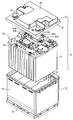
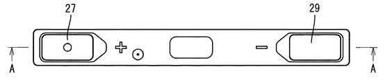
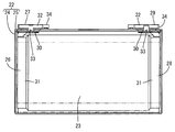
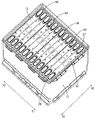
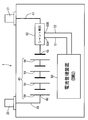
- FIG. 1 An exploded perspective view of the power storage device Plan view of power storage element AA cross-sectional view of FIG. A perspective view showing a state in which a power storage element is housed in the main body.
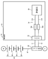
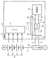
- the figure which shows the basic configuration of a power storage device The figure which shows the circuit structure of the BMU board
- Perspective view of BMU board Perspective view of BMU board
- the power storage element management device is a current having a substrate, a heat source provided on the substrate, and a pair of wirings connected to a resistor provided on the substrate and connected in series with the power storage element.
- a measuring circuit is provided, and a heat insulating portion is provided between the heat source and the pair of wirings.
- the above management device since a heat insulating portion is provided between the heat source and the pair of wirings, the heat generated by the heat source is cut off by the heat insulating portion on the way to the pair of wirings through the substrate, resulting in a charged state. It can be estimated accurately. Therefore, the above-mentioned management device is effective when the current integration method is used.
- the heat insulating portion may be a slit provided in the substrate.
- the measurement error caused by the Seebeck effect can be suppressed by a simple configuration in which a slit is provided in the substrate.
- the parts provided in the pair of wirings may be arranged so that the distances from both ends of the slits are equal.
- the distance from both ends of the slit to the component is equal, so even if heat is transferred to the component, the difference in the temperature gradient of the component between the pair of wires. Is unlikely to occur.
- the slit is configured to include a first slit and a second slit, and between the first slit and the second slit in the substrate, a heat source side and a pair of wiring sides are provided.
- a connecting portion may be provided to connect the two. Since the connecting portion is provided between the first slit and the second slit, it is possible to suppress a decrease in the strength of the substrate due to the provision of the slit, as compared with the case where the connecting portion is not provided.
- the substrate is divided into a first substrate provided with the heat source and a second substrate provided with the pair of wirings, and the first substrate and the second substrate are connected cables.
- the heat insulating portion may be a space between the first substrate and the second substrate. Since the substrate is divided into a first substrate and a second substrate and the space between the first substrate and the second substrate is a heat insulating portion, the same effect as when a slit is provided as the heat insulating portion can be obtained.
- the charged state of the power storage element may be calculated by integrating the measured current values.
- a power storage device including a plurality of power storage elements and the above-mentioned power storage element management device may be used.
- a vehicle equipped with the power storage device may be used. The state of charge can be estimated accurately in a vehicle equipped with a management device.
- the first embodiment will be described with reference to FIGS. 1 to 11.
- the power storage device 1 according to the first embodiment and the automobile 2 (an example of a vehicle) including the power storage device 1 will be described with reference to FIG.
- the automobile 2 shown in FIG. 1 is an engine automobile and includes a starter for starting the engine.
- the power storage device 1 is a start power storage device mounted on the automobile 2 to supply electric power to the starter.
- FIG. 1 shows a case where the power storage device 1 (shown by the solid line) is housed in the engine room 2A, the power storage device 1 (shown by the alternate long and short dash line) may be housed under the floor or in the trunk of the vehicle.
- the power storage device 1 includes an exterior body 10 and a plurality of power storage elements 12 housed inside the exterior body 10.
- the exterior body 10 is composed of a main body 13 made of a synthetic resin material and a lid body 14 made of a synthetic resin material.
- the main body 13 has a bottomed cylindrical shape, and is composed of a bottom surface portion 15 having a rectangular shape in a plan view and four side surface portions 16 having a cylindrical shape rising from four sides thereof.
- An upper opening 17 is formed at the upper end portion by the four side surface portions 16.
- the lid body 14 has a rectangular shape in a plan view, and the frame body 18 extends downward from its four sides.
- the lid 14 closes the upper opening 17 of the main body 13.
- a substantially T-shaped protrusion 19 in a plan view is formed on the upper surface of the lid 14.
- the positive electrode external terminal 20 is fixed to one corner of the two locations where the protrusion 19 is not formed on the upper surface of the lid 14, and the negative electrode external terminal 21 is fixed to the other corner.
- the power storage element 12 is a rechargeable secondary battery, specifically, for example, a lithium ion battery. More specifically, the power storage element 12 is a so-called iron-based lithium ion battery in which lithium iron phosphate (LFP) is contained in the positive electrode active material of the electrode body 23, which will be described later.
- LFP lithium iron phosphate
- the power storage element 12 contains an electrode body 23 together with a non-aqueous electrolyte in a rectangular parallelepiped case 22.
- the case 22 is composed of a case main body 24 and a cover 25 that closes an opening above the case main body 24.
- the electrode body 23 is a porous resin film between a negative electrode element in which an active material is applied to a base material made of copper foil and a positive electrode element in which an active material is applied to a base material made of aluminum foil. It is an arrangement of separators made of. All of these are strip-shaped, and the negative electrode element and the positive electrode element are wound flat so as to be accommodated in the case body 24 in a state where the negative electrode element and the positive electrode element are displaced on opposite sides in the width direction with respect to the separator. There is.
- the positive electrode terminal 27 is connected to the positive electrode element via the positive electrode current collector 26.
- the negative electrode terminal 29 is connected to the negative electrode element via the negative electrode current collector 28.
- the positive electrode current collector 26 and the negative electrode current collector 28 have a flat plate-shaped pedestal portion 30 and leg portions 31 extending from the pedestal portion 30. A through hole is formed in the pedestal portion 30.
- the leg 31 is connected to a positive electrode element or a negative electrode element.
- the positive electrode terminal 27 and the negative electrode terminal 29 have a terminal main body portion 32 and a shaft portion 33 protruding downward from the center portion of the lower surface thereof. Among them, the terminal body portion 32 and the shaft portion 33 of the positive electrode terminal 27 are integrally molded with aluminum (single material).
- the terminal body portion 32 is made of aluminum and the shaft portion 33 is made of copper, and these are assembled.
- the terminal body 32 of the positive electrode terminal 27 and the negative electrode terminal 29 is arranged at both ends of the cover 25 via a gasket 34 made of an insulating material, and is exposed to the outside from the gasket 34.
- a plurality of (for example, 12) power storage elements 12 are housed in the main body 13 in a state of being arranged side by side in the width direction.
- one cell 64 is composed of three power storage elements 12.
- four sets of cells 64 are arranged from one end side to the other end side (directions from arrows Y1 to Y2) of the main body 13.
- the terminal polarities of the adjacent power storage elements 12 are the same, and in the adjacent sets of cells 64, the terminal polarities of the adjacent power storage elements 12 are opposite to each other.
- the arrow X1 side is the negative electrode and the arrow X2 side is the positive electrode.
- the arrow X1 side is the positive electrode and the arrow X2 side is the negative electrode. Further, the cells 64 of the third set adjacent to the second set have the same arrangement as the first set, and the cells 64 of the fourth set adjacent to the third set have the same arrangement as the second set.
- terminal bus bars (connecting members) 36 to 40 as conductive members are connected to the positive electrode terminal 27 and the negative electrode terminal 29 by welding.
- the positive electrode terminal 27 group is connected by the first bus bar 36.
- the negative electrode terminal 29 group of the first group and the positive electrode terminal 27 group of the second group are connected by the second bus bar 37 on the arrow X1 side.
- the negative electrode terminal 29 group of the second group and the positive electrode terminal 27 group of the third group are connected by the third bus bar 38 on the arrow X2 side.
- the negative electrode terminal 29 group of the third group and the positive electrode terminal 27 group of the fourth group are connected by the fourth bus bar 39 on the arrow X1 side.
- the negative electrode terminal 29 group is connected by the fifth bus bar 40.
- the first bus bar 36 located at one end of the electric flow includes the first electronic device 42A (for example, a fuse), the second electronic device 42B (for example, a relay), the connection bus bar 43, and the bus bar terminal. It is connected to the positive electrode external terminal 20 via (not shown).
- the fifth bus bar 40 located at the other end of the flow of electricity is connected to the negative electrode external terminal 21 via the connecting bus bars 44A and 44B and the negative electrode bus bar terminal (not shown).
- each power storage element 12 can be charged and discharged via the positive electrode external terminal 20 and the negative electrode external terminal 21.
- the electronic devices 42A and 42B and the connecting bus bars 43, 44A and 44B are attached to a circuit board unit 41 arranged above a plurality of energy storage elements 12 arranged in a stacked manner.
- the bus bar terminal is arranged on the lid 14.
- the power storage device 1 includes an assembled battery 45 composed of four cells 64 connected in series, a shunt resistor (an example of a resistor) 60, and a battery management device (BMU: Battery Management Unit) 50. Etc. are provided.
- the assembled battery 45 is connected to the external terminals 20 and 21 via the power lines 46 and 47.
- the power line 46 is a power line that connects the positive electrode external terminal 20 and the positive electrode 48 of the assembled battery 45.
- the power line 47 is a power line that connects the negative electrode external terminal 21 and the negative electrode 49 of the assembled battery 45.
- a positive electrode 48 is connected to the first bus bar 36 shown in FIG. 6, and a negative electrode 49 is connected to the fifth bus bar 40.
- the shunt resistor 60 is located on the power line 47 and is connected in series with the assembled battery 45.
- the battery management device 50 is connected to the shunt resistor 60 via a pair of measurement lines 51 and 52.
- the shunt resistor 60 has two measuring terminals 60A and 60B that are separated from each other in the current flow direction.
- the measurement lines 51 and 52 are connected to the measurement terminals 60A and 60B.
- the measurement terminals 60A and 60B are located at both ends of a resistor body provided inside the shunt resistor 60.
- the resistance body is made of, for example, manganin and has a predetermined resistance value.
- the pair of measurement lines 51 and 52 is a pair of wirings that sandwich the resistance body.
- the pair of measurement lines is a pair of wires sandwiching manganin.
- the power supply management device 50 has a BMU board 53, and a current measurement circuit 54 is formed on the BMU board 53.
- the current measurement circuit 54 includes a connector 55, a first noise filter 56A, a second noise filter 56B, a first wiring 57A, a second wiring 57B, a measurement IC 58, and the like.
- the noise filters 56A and 56B have a role of removing noise from the signals flowing through the wirings 57A and 57B, and can suppress the occurrence of current measurement error due to the noise.
- the first wiring 57A is an internal wiring that connects the connector 55, the first noise filter 56A, and the measurement IC 58 in series.
- the second wiring 57B is an internal wiring that connects the connector 55, the second noise filter 56B, and the measurement IC 58 in series.
- the first wiring 57A is connected to the measurement line 51 via the connector 55, and the second wiring 57B is connected to the measurement line 52 via the connector 55.
- the current of the assembled battery 45 can be measured by detecting the voltage generated at both ends of the resistance body of the shunt resistor 60 with the measuring IC 58.
- the first wiring 57A includes a connection portion 61A with the connector 55, a connection portion 61B with both ends of the first noise filter 56A, a connection portion 61C with the measurement IC 58, and the like.
- the connection portions 61A, 61B, and 61C are all made of tin-plated copper, and the other parts are all made of copper.
- the second wiring 57B includes a connection portion 62A with the connector 55, a connection portion 62B with both ends of the second noise filter 56B, a connection portion 62C with the measurement IC 58, and the like.
- the connection portions 62A, 62B, and 62C are all made of tin-plated copper, and the other parts are all made of copper.
- a heat source such as a balancer 63 provided on the BMU substrate 53 can be mentioned. Since one cell 64 is composed of three power storage elements 12, four cells 64 are connected in series in the case of a 12V battery.
- the balancer 63 equalizes the capacity difference between the cells 64 caused by variations in the self-discharge of the cells 64 and the like.
- the balancer 63 consumes the electric energy of the cell 64 having a large capacity by resistance discharge to equalize the capacity difference, and the heat generated during the discharge causes a temperature imbalance in the BMU substrate 53. Let me. Therefore, when the balancer 63 is operated and the heat is propagated to the current measurement circuit 54 of the BMU substrate 53, and the temperature gradient of the first wiring 57A and the temperature gradient of the second wiring 57B are different, a current measurement error occurs. appear.
- a slit 65 is provided as a heat insulating portion for preventing heat propagation.
- the slit 65 is provided between the balancer 63 and the current measurement circuit 54 on the BMU substrate 53.
- the slit 65 has an elongated shape extending straight along the first wiring 57A, and is located between the connector 55 and the measurement IC 58 in the wiring direction of the first wiring 57A.
- One end 65A of the slit 65 is located near the connector 55, and the other end 65B of the slit 65 is located near the measurement IC 58.
- a space exists inside the slit 65, and this space functions as a heat insulating portion.
- the electromotive force generated by the temperature gradient of the first wiring 57A is canceled by the electromotive force generated by the temperature gradient of the second wiring 57B, and the current measurement error can be suppressed.
- the first noise filter 56A and the second noise filter 56B which are far from both ends 65A and 65B of the slit 65, are arranged so that the distances from both ends 65A and 65B of the slit 65 are substantially equal.
- the first noise filter 56A so that the distance L1 from one end 65A of the slit 65 to the first noise filter 56A and the distance L2 from the other end 65B of the slit 65 to the first noise filter 56A are substantially equal. Is placed.
- This arrangement is the same for the second noise filter 56B.
- heat is evenly transferred from both sides to the noise filters 56A and 56B, so that a difference in temperature gradient is unlikely to occur. Therefore, even if heat circulates from both ends 65A and 65B of the slit 65, a difference in temperature gradient is unlikely to occur, and a current measurement error can be suppressed.
- the power management device 50 since the slit 65 is provided between the balancer 63 and the pair of wirings 57A and 57B, the heat generated in the balancer 63 is slit on the way to the pair of wirings 57A and 57B through the BMU substrate 53. It is cut off at 65, and as a result, the charging state can be estimated accurately. According to the power management device 50, the measurement error caused by the Seebeck effect can be suppressed by a simple configuration in which the slit 65 is provided in the BMU substrate 53.
- the power management device 50 when the heat generated by the balancer 63 goes around the slits 65 and heads toward the noise filters 56A and 56B, the distances from both ends of the slits 65 to the noise filters 56A and 56B are equal. Even if heat is transferred to the noise filters 56A and 56B, the difference in temperature gradient between the noise filters 56A and 56B between the pair of wires 57A and 57B is unlikely to occur. According to the automobile 2 provided with the power management device 50, the charging state can be estimated accurately.
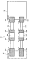
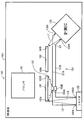
- the power supply management device 150 has a BMU board 153, and the BMU board 153 includes a balancer 163 and a current measurement circuit 154.
- the current measurement circuit 154 includes a connector 155, a first noise filter 156A, a second noise filter 156B, a measurement IC 158, a first wiring 157A, and a second wiring 157B.
- the current measurement circuit 154 of the second embodiment is provided with the first slit 165 and the second slit 166 instead of the slit 65 of the first embodiment, and the description of the same configuration as that of the first embodiment will be omitted.
- the first wiring 157A is an internal wiring that connects the connector 155, the first noise filter 156A, and the measurement IC 158 in series.
- the second wiring 157B is an internal wiring that connects the connector 155, the second noise filter 156B, and the measurement IC 158 in series.
- the first wiring 157A is connected to the measurement line 51 via the connector 155
- the second wiring 157B is connected to the measurement line 52 via the connector 155.
- the current of the assembled battery 45 can be measured by detecting the voltage generated at both ends of the resistance body of the shunt resistor 60 with the measuring IC 158.
- a first slit 165 and a second slit 166 are provided between the balancer 163 and the current measurement circuit 154 on the BMU substrate 153. Both the first slit 165 and the second slit 166 have an elongated shape extending straight along the first wiring 157A.
- a connecting portion 167 is provided between the first slit 165 and the second slit 166 in the BMU substrate 153. The connecting portion 167 is a portion of the BMU substrate 153 that connects the balancer 163 side and the pair of wirings 157A and 157B sides.
- Both slits 165 and 166 are arranged in a straight line so that the other end 165B of both ends 165A and 165B of the first slit 165 and one end 166A of both ends 166A and 166B of the second slit 166 are adjacent to each other. Have been placed. A space exists inside both slits 165 and 166, and this space functions as a heat insulating portion. In this way, it is possible to prevent heat from propagating from the balancer 163 to the current measurement circuit 154. As a result, a temperature gradient is unlikely to occur in the first wiring 157A and the second wiring 157B, and an electromotive force due to the Seebeck effect is unlikely to occur, so that a current measurement error can be suppressed.
- the first noise filter 156A and the second noise filter 156B are located on a line extending at the center of the first slit 165 in an arrangement orthogonal to the first slit 165.
- the first noise filter 156A and the second noise filter 156B are arranged so that the distances from both ends 165A and 165B of the first slit 165 are substantially equal. Specifically, the distance L3 from one end 165A of the first slit 165 to the first noise filter 156A and the distance L4 from the other end 165B of the first slit 165 to the first noise filter 156A are approximately equal.
- 1 Noise filter 156A is arranged. This arrangement is the same for the second noise filter 156B.
- the end on the connector 155 side is 155A at one end, and the end on the measurement IC 158 side is the other end 158A.
- the end on the connector 155 side is 155B at one end, and the end on the measurement IC 158 side is 158B at the other end.
- the connector 155 is arranged so that the distance L5 from one end 165A of the first slit 165 to one end 155A of the first wiring 157A and the distance L6 from one end 165A of the first slit 165 to one end 155B of the second wiring 157B are substantially equal. Has been done. Therefore, even if heat wraps around from one end 165A of the first slit 165, the heat is evenly transferred to the ends 155A and 155B of the wirings 157A and 157B.
- the electromotive force generated by the temperature gradient of one end 155A of the first wiring 157A is canceled by the electromotive force generated by the temperature gradient of one end 155B of the second wiring 157B, and the current measurement error is caused. Can be suppressed.
- the distance L7 from the other end 166B of the second slit 166 to the other end 158A of the first wiring 157A and the distance L8 from the other end 166B of the second slit 166 to the other end 158B of the second wiring 157B are approximately equal.
- the measurement IC 158 is arranged. Therefore, even if heat wraps around from the other end 166B of the second slit 166, the heat is evenly transferred to the other ends 158A and 158B of the wirings 157A and 157B.
- the electromotive force generated by the temperature gradient of the other end 158A of the first wiring 157A is canceled by the electromotive force generated by the temperature gradient of the other end 158B of the second wiring 157B, and the current measurement The error can be suppressed.
- the connecting portion 167 is provided between the first slit 165 and the second slit 166, when the connecting portion 167 is not provided (for example, a single slit as in the first embodiment). Compared with the case where 65 is provided), the decrease in strength of the BMU substrate 153 due to the provision of the pair of slits 165 and 166 can be suppressed.
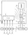
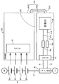
- the power supply management device 250 has a BMU board 253.
- the BMU board 253 is divided into a first board 253A and a second board 253B, and the first board 253A and the second board 253B are electrically connected by a connection cable 253C.
- the first substrate 253A includes a balancer 63.
- the second substrate 253B includes a connector 55, a first noise filter 56A, a second noise filter 56B, a measurement IC 58, a first wiring 57A, and a second wiring 57B.
- the BMU substrate 253 of the third embodiment is obtained by dividing the BMU substrate 53 of the first embodiment into two sheets, and the description of the same configuration as that of the first embodiment will be omitted.
- a heat insulating space 265 is provided as a heat insulating portion for preventing heat propagation.
- the heat insulating space 265 is a space formed between the first substrate 253A and the second substrate 253B. According to the heat insulating space 265, it is possible to suppress heat from propagating from the balancer 63 of the first substrate 253A to the current measuring circuit 54 of the second substrate 253B. As a result, a temperature gradient is unlikely to occur in the first wiring 57A and the second wiring 57B, and an electromotive force due to the Seebeck effect is unlikely to occur, so that a current measurement error can be suppressed.
- the BMU board is divided into the first board 253A and the second board 253B, and the heat insulating space 265 between the first board 253A and the second board 253B is a heat insulating part. The same effect as when provided can be obtained.
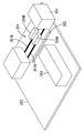
- the power management device 350 As shown in FIG. 14, the power management device 350 according to the fourth embodiment is provided on the side surface of the assembled battery 345 composed of four cells. A positive electrode 348 and a negative electrode 349 are provided on the upper surface of the assembled battery 345. The shunt resistor 360 is located on a power line 347 connecting the negative electrode 349 of the assembled battery 345 and the negative electrode external terminal (not shown), and is connected in series with the assembled battery 345.
- the power supply management device 350 is connected to the shunt resistor 360 via a pair of measurement lines 351 and 352.
- the power management device 350 has a BMU board 353 shown in FIG. 15, and a current measurement circuit 354 is formed on the BMU board 353.
- the current measurement circuit 354 includes a connector 355, a first noise filter 356A, a second noise filter 356B, a first wiring 357A, a second wiring 357B, a measurement IC 358, and the like.
- the first wiring 357A is an internal wiring that connects the connector 355, the first noise filter 356A, and the measurement IC 358 in series.
- the second wiring 357B is an internal wiring that connects the connector 355, the second noise filter 356B, and the measurement IC 358 in series.
- the first wiring 357A is connected to the measurement line 351 via the connector 355, and the second wiring 357B is connected to the measurement line 352 via the connector 355.
- the current of the assembled battery 345 can be measured by detecting the voltage generated at both ends of the resistance body of the shunt resistor 360 with the measuring IC 358.
- the BMU substrate 353 of the present embodiment is provided with a slit 365 as a heat insulating portion for preventing heat propagation.
- the slit 365 is provided between the balancer 363 on the BMU substrate 353 and the current measurement circuit 354.
- the BMU substrate 353 and the shunt resistor 360 are separated from each other, but they have the same effects as those in the first embodiment. That is, a temperature gradient is unlikely to occur in the first wiring 357A and the second wiring 357B, and an electromotive force due to the Seebeck effect is unlikely to occur, so that a current measurement error can be suppressed.
- the slit is illustrated as the heat insulating portion, but a bottomed recess may be provided as the heat insulating portion, or a heat insulating member different from the substrate may be used.
- the one provided with the first slit 165 and the second slit 166 is illustrated, but three or more slits may be provided.
- the BMU substrate 253 is divided into the first substrate 253A and the second substrate 253B, but the BMU substrate 253 may be divided into three or more substrates.
- the balancer is exemplified as the heat source, but a heat source other than the balancer may be used.
- the noise filter is illustrated as a component provided in the pair of wirings, a component other than the noise filter may be used.
- the iron-based power storage element 12 has been described as an example of the power storage element 12, but the power storage element 12 is not limited to the iron-based power storage element 12, and other lithium ion batteries may be used.
- the power storage element 12 for starting has been described as an example, but the application of the power storage element 12 is not limited to this.
- the power storage element 12 may be mounted on an electric vehicle or a hybrid vehicle to supply electric power to auxiliary equipment, or mounted on a forklift or an unmanned transport vehicle (AGV: Automatic Guided Vehicle) traveling by an electric motor. It may be for a mobile body that is used to supply electric power to an electric motor.
- AGV Automatic Guided Vehicle
- the power storage element 12 may be used in an uninterruptible power supply (UPS), or may be used in a mobile terminal or the like. It may be a power storage device used for peak shift, or it may be a power storage device that stores renewable energy.
- UPS uninterruptible power supply
- the lithium ion battery has been described as an example of the power storage element, but the power storage element is not limited to this.
- the power storage element may be a capacitor that involves an electrochemical reaction.
- the first board 253A and the second board 253B are connected by the connection cable 253C, but the first board 253A and the second board 253B may be connected by the connection connector.
- the connecting portion in addition to connecting with the connection cable 253C, it may be connected with a connection connector or may be connected by wireless communication.
- 1 power storage device 2 automobiles (an example of a vehicle) 50 Battery management device, 53 BMU board, 54 Current measurement circuit, 56A 1st noise filter (example of parts), 56B 2nd noise filter (example of parts), 57A 1st wiring, 57B 2nd wiring, 60 shunt resistance ( Resistor), 63 balancer (an example of heat source), 65 slits (an example of heat insulating part)
- 150 power supply management device 150 power supply management device, 153 BMU board, 154 current measurement circuit, 156A first noise filter (example of parts), 156B second noise filter (example of parts), 157A first wiring, 157B second wiring, 163 balancer (heat source) (Example), 165 1st slit (an example of heat insulating part), 166 2nd slit (an example of heat insulating part), 167 connecting part, 250 power supply management device, 253 BMU board, 253A 1st board, 253B 2nd board, 253C Connection cable (example of connection part), 265 heat insulation space (example of heat insulation part)
Landscapes
- Engineering & Computer Science (AREA)
- Power Engineering (AREA)
- Physics & Mathematics (AREA)
- General Physics & Mathematics (AREA)
- Manufacturing & Machinery (AREA)
- Chemical & Material Sciences (AREA)
- Chemical Kinetics & Catalysis (AREA)
- Electrochemistry (AREA)
- General Chemical & Material Sciences (AREA)
- Secondary Cells (AREA)
- Measuring Instrument Details And Bridges, And Automatic Balancing Devices (AREA)
- Charge And Discharge Circuits For Batteries Or The Like (AREA)
Applications Claiming Priority (2)
| Application Number | Priority Date | Filing Date | Title |
|---|---|---|---|
| JP2020-068424 | 2020-04-06 | ||
| JP2020068424A JP7539019B2 (ja) | 2020-04-06 | 2020-04-06 | 蓄電素子の管理装置、蓄電装置、及び、車両 |
Publications (1)
| Publication Number | Publication Date |
|---|---|
| WO2021205870A1 true WO2021205870A1 (ja) | 2021-10-14 |
Family
ID=78022278
Family Applications (1)
| Application Number | Title | Priority Date | Filing Date |
|---|---|---|---|
| PCT/JP2021/012107 Ceased WO2021205870A1 (ja) | 2020-04-06 | 2021-03-24 | 蓄電素子の管理装置、蓄電装置、及び、車両 |
Country Status (2)
| Country | Link |
|---|---|
| JP (1) | JP7539019B2 (cg-RX-API-DMAC7.html) |
| WO (1) | WO2021205870A1 (cg-RX-API-DMAC7.html) |
Families Citing this family (1)
| Publication number | Priority date | Publication date | Assignee | Title |
|---|---|---|---|---|
| JP7151921B1 (ja) * | 2021-10-08 | 2022-10-12 | 大日本印刷株式会社 | 波長変換シート用フィルム、波長変換シート、バックライト、及び、表示装置 |
Citations (3)
| Publication number | Priority date | Publication date | Assignee | Title |
|---|---|---|---|---|
| JP2016034221A (ja) * | 2014-07-31 | 2016-03-10 | 株式会社東芝 | 電池監視装置、蓄電池モジュール及び蓄電池ユニット |
| WO2018199222A1 (ja) * | 2017-04-28 | 2018-11-01 | 株式会社Gsユアサ | 電流検出装置、管理装置、エンジン始動用のバッテリ |
| JP2019138706A (ja) * | 2018-02-07 | 2019-08-22 | 三洋電機株式会社 | 電池の電流検出器と電流検出器を備える電動車両及び蓄電装置 |
Family Cites Families (3)
| Publication number | Priority date | Publication date | Assignee | Title |
|---|---|---|---|---|
| US6304062B1 (en) | 1999-10-28 | 2001-10-16 | Powersmart, Inc. | Shunt resistance device for monitoring battery state of charge |
| JP2015109236A (ja) | 2013-12-05 | 2015-06-11 | パナソニックIpマネジメント株式会社 | バッテリセンサ装置 |
| WO2016194368A1 (ja) | 2015-06-04 | 2016-12-08 | 日本電気株式会社 | 実装基板及び蓄電池の電流検出装置 |
-
2020
- 2020-04-06 JP JP2020068424A patent/JP7539019B2/ja active Active
-
2021
- 2021-03-24 WO PCT/JP2021/012107 patent/WO2021205870A1/ja not_active Ceased
Patent Citations (3)
| Publication number | Priority date | Publication date | Assignee | Title |
|---|---|---|---|---|
| JP2016034221A (ja) * | 2014-07-31 | 2016-03-10 | 株式会社東芝 | 電池監視装置、蓄電池モジュール及び蓄電池ユニット |
| WO2018199222A1 (ja) * | 2017-04-28 | 2018-11-01 | 株式会社Gsユアサ | 電流検出装置、管理装置、エンジン始動用のバッテリ |
| JP2019138706A (ja) * | 2018-02-07 | 2019-08-22 | 三洋電機株式会社 | 電池の電流検出器と電流検出器を備える電動車両及び蓄電装置 |
Also Published As
| Publication number | Publication date |
|---|---|
| JP7539019B2 (ja) | 2024-08-23 |
| JP2021166429A (ja) | 2021-10-14 |
Similar Documents
| Publication | Publication Date | Title |
|---|---|---|
| US8674703B2 (en) | Car battery system | |
| US8962168B2 (en) | Storage battery module | |
| US9024572B2 (en) | Battery module, battery system and electric vehicle | |
| KR101943493B1 (ko) | 배터리 모듈 어셈블리 및 이를 포함하는 배터리 팩 | |
| JP6046864B1 (ja) | 2つの異なるバッテリセルの2つのセル電流の差分を測定する装置を備えた、複数の電気化学的なバッテリセルを有するバッテリパック | |
| EP3550660A1 (en) | Battery module, and battery pack and vehicle comprising same | |
| US20130260193A1 (en) | Assembled battery wiring member and assembled battery module | |
| CN110337736B (zh) | 电池包、托架 | |
| US20170003349A1 (en) | Arc suppression and protection of integrated flex circuit fuses for high voltage applications under chemically harsh environments | |
| KR20190106161A (ko) | 외부 단락 방지 구조가 적용된 배터리 모듈을 이용한 배터리 팩 | |
| JP7765756B2 (ja) | 電流計測装置、蓄電装置 | |
| CN117795812A (zh) | 蓄电装置以及蓄电装置的异常放电检测方法 | |
| JP7539019B2 (ja) | 蓄電素子の管理装置、蓄電装置、及び、車両 | |
| US20240410955A1 (en) | Battery pack | |
| JP2025156859A (ja) | 蓄電装置の管理システム | |
| US20210094439A1 (en) | Management device and energy storage apparatus | |
| KR20230141586A (ko) | 전지 팩, 전기 자동차 및 전지 팩 조립 방법 | |
| WO2013108786A1 (ja) | 電源装置、これを備える車両及び蓄電装置並びに電源装置用の回路基板 | |
| JP2021150131A (ja) | 蓄電装置 | |
| RU2794728C1 (ru) | Устройство контроля модуля аккумуляторной батареи и модуль аккумуляторной батареи для электромобиля | |
| US20250138101A1 (en) | Battery pack | |
| KR20250178890A (ko) | 배터리조립체 및 이의 모니터링 방법 | |
| CN119213619A (zh) | 电池组 | |
| WO2020246285A1 (ja) | 監視ユニット、蓄電装置、監視ユニットの起動方法 |
Legal Events
| Date | Code | Title | Description |
|---|---|---|---|
| 121 | Ep: the epo has been informed by wipo that ep was designated in this application |
Ref document number: 21785634 Country of ref document: EP Kind code of ref document: A1 |
|
| NENP | Non-entry into the national phase |
Ref country code: DE |
|
| 122 | Ep: pct application non-entry in european phase |
Ref document number: 21785634 Country of ref document: EP Kind code of ref document: A1 |