WO2021205624A1 - Dispositif de traitement d'image, procédé de traitement d'image, procédé de navigation et système d'endoscope - Google Patents
Dispositif de traitement d'image, procédé de traitement d'image, procédé de navigation et système d'endoscope Download PDFInfo
- Publication number
- WO2021205624A1 WO2021205624A1 PCT/JP2020/016037 JP2020016037W WO2021205624A1 WO 2021205624 A1 WO2021205624 A1 WO 2021205624A1 JP 2020016037 W JP2020016037 W JP 2020016037W WO 2021205624 A1 WO2021205624 A1 WO 2021205624A1
- Authority
- WO
- WIPO (PCT)
- Prior art keywords
- image
- acquisition condition
- analysis
- unit
- display
- Prior art date
Links
Images


Classifications
-
- A—HUMAN NECESSITIES
- A61—MEDICAL OR VETERINARY SCIENCE; HYGIENE
- A61B—DIAGNOSIS; SURGERY; IDENTIFICATION
- A61B1/00—Instruments for performing medical examinations of the interior of cavities or tubes of the body by visual or photographical inspection, e.g. endoscopes; Illuminating arrangements therefor
- A61B1/00002—Operational features of endoscopes
- A61B1/00004—Operational features of endoscopes characterised by electronic signal processing
- A61B1/00009—Operational features of endoscopes characterised by electronic signal processing of image signals during a use of endoscope
-
- A—HUMAN NECESSITIES
- A61—MEDICAL OR VETERINARY SCIENCE; HYGIENE
- A61B—DIAGNOSIS; SURGERY; IDENTIFICATION
- A61B1/00—Instruments for performing medical examinations of the interior of cavities or tubes of the body by visual or photographical inspection, e.g. endoscopes; Illuminating arrangements therefor
- A61B1/04—Instruments for performing medical examinations of the interior of cavities or tubes of the body by visual or photographical inspection, e.g. endoscopes; Illuminating arrangements therefor combined with photographic or television appliances
- A61B1/045—Control thereof
-
- A—HUMAN NECESSITIES
- A61—MEDICAL OR VETERINARY SCIENCE; HYGIENE
- A61B—DIAGNOSIS; SURGERY; IDENTIFICATION
- A61B1/00—Instruments for performing medical examinations of the interior of cavities or tubes of the body by visual or photographical inspection, e.g. endoscopes; Illuminating arrangements therefor
- A61B1/00002—Operational features of endoscopes
- A61B1/00004—Operational features of endoscopes characterised by electronic signal processing
- A61B1/00006—Operational features of endoscopes characterised by electronic signal processing of control signals
-
- A—HUMAN NECESSITIES
- A61—MEDICAL OR VETERINARY SCIENCE; HYGIENE
- A61B—DIAGNOSIS; SURGERY; IDENTIFICATION
- A61B1/00—Instruments for performing medical examinations of the interior of cavities or tubes of the body by visual or photographical inspection, e.g. endoscopes; Illuminating arrangements therefor
- A61B1/00002—Operational features of endoscopes
- A61B1/00004—Operational features of endoscopes characterised by electronic signal processing
- A61B1/00009—Operational features of endoscopes characterised by electronic signal processing of image signals during a use of endoscope
- A61B1/000094—Operational features of endoscopes characterised by electronic signal processing of image signals during a use of endoscope extracting biological structures
-
- A—HUMAN NECESSITIES
- A61—MEDICAL OR VETERINARY SCIENCE; HYGIENE
- A61B—DIAGNOSIS; SURGERY; IDENTIFICATION
- A61B1/00—Instruments for performing medical examinations of the interior of cavities or tubes of the body by visual or photographical inspection, e.g. endoscopes; Illuminating arrangements therefor
- A61B1/00002—Operational features of endoscopes
- A61B1/00004—Operational features of endoscopes characterised by electronic signal processing
- A61B1/00009—Operational features of endoscopes characterised by electronic signal processing of image signals during a use of endoscope
- A61B1/000095—Operational features of endoscopes characterised by electronic signal processing of image signals during a use of endoscope for image enhancement
-
- A—HUMAN NECESSITIES
- A61—MEDICAL OR VETERINARY SCIENCE; HYGIENE
- A61B—DIAGNOSIS; SURGERY; IDENTIFICATION
- A61B1/00—Instruments for performing medical examinations of the interior of cavities or tubes of the body by visual or photographical inspection, e.g. endoscopes; Illuminating arrangements therefor
- A61B1/06—Instruments for performing medical examinations of the interior of cavities or tubes of the body by visual or photographical inspection, e.g. endoscopes; Illuminating arrangements therefor with illuminating arrangements
- A61B1/0638—Instruments for performing medical examinations of the interior of cavities or tubes of the body by visual or photographical inspection, e.g. endoscopes; Illuminating arrangements therefor with illuminating arrangements providing two or more wavelengths
-
- A—HUMAN NECESSITIES
- A61—MEDICAL OR VETERINARY SCIENCE; HYGIENE
- A61B—DIAGNOSIS; SURGERY; IDENTIFICATION
- A61B1/00—Instruments for performing medical examinations of the interior of cavities or tubes of the body by visual or photographical inspection, e.g. endoscopes; Illuminating arrangements therefor
- A61B1/06—Instruments for performing medical examinations of the interior of cavities or tubes of the body by visual or photographical inspection, e.g. endoscopes; Illuminating arrangements therefor with illuminating arrangements
- A61B1/0655—Control therefor
-
- A—HUMAN NECESSITIES
- A61—MEDICAL OR VETERINARY SCIENCE; HYGIENE
- A61B—DIAGNOSIS; SURGERY; IDENTIFICATION
- A61B1/00—Instruments for performing medical examinations of the interior of cavities or tubes of the body by visual or photographical inspection, e.g. endoscopes; Illuminating arrangements therefor
- A61B1/06—Instruments for performing medical examinations of the interior of cavities or tubes of the body by visual or photographical inspection, e.g. endoscopes; Illuminating arrangements therefor with illuminating arrangements
- A61B1/0661—Endoscope light sources
-
- A—HUMAN NECESSITIES
- A61—MEDICAL OR VETERINARY SCIENCE; HYGIENE
- A61B—DIAGNOSIS; SURGERY; IDENTIFICATION
- A61B1/00—Instruments for performing medical examinations of the interior of cavities or tubes of the body by visual or photographical inspection, e.g. endoscopes; Illuminating arrangements therefor
- A61B1/313—Instruments for performing medical examinations of the interior of cavities or tubes of the body by visual or photographical inspection, e.g. endoscopes; Illuminating arrangements therefor for introducing through surgical openings, e.g. laparoscopes
- A61B1/3132—Instruments for performing medical examinations of the interior of cavities or tubes of the body by visual or photographical inspection, e.g. endoscopes; Illuminating arrangements therefor for introducing through surgical openings, e.g. laparoscopes for laparoscopy
-
- G—PHYSICS
- G06—COMPUTING; CALCULATING OR COUNTING
- G06T—IMAGE DATA PROCESSING OR GENERATION, IN GENERAL
- G06T7/00—Image analysis
- G06T7/0002—Inspection of images, e.g. flaw detection
- G06T7/0012—Biomedical image inspection
-
- G—PHYSICS
- G06—COMPUTING; CALCULATING OR COUNTING
- G06T—IMAGE DATA PROCESSING OR GENERATION, IN GENERAL
- G06T2207/00—Indexing scheme for image analysis or image enhancement
- G06T2207/10—Image acquisition modality
- G06T2207/10068—Endoscopic image
Definitions
- the present invention relates to an image processing device, an image processing method, a navigation method, and an endoscope system for performing navigation when observing an image.
- CAD computer-aided diagnosis
- two analysis results for the first and second medical images can be displayed so that the positions or ranges (sizes) can be compared for analysis.
- Techniques that facilitate confirmation of results are disclosed.
- real-time medical images acquired by an endoscope or the like are not only image-processed for image analysis but also displayed on a monitor or the like, which is an extremely useful image of the affected area or the like in surgery or examination. Information can be provided to the surgeon.
- the acquired image is not optimized for visual inspection at the time of surgery, examination, etc., and the optimum support is not always provided to the operator.
- the present invention provides an image processing device, an image processing method, a navigation method, and an endoscopic system capable of providing extremely effective support to an operator by optimizing the image acquisition conditions. The purpose.
- the image processing apparatus includes a first image based on a display acquisition condition for acquiring a display image and a second image based on an analysis acquisition condition for acquiring an image for image analysis.
- the acquisition condition specification unit that sets the first acquisition condition including the display acquisition condition and the second acquisition condition including the display acquisition condition and the analysis acquisition condition for the image acquisition unit to acquire the image, and the image.
- An image analysis unit that performs image analysis on the image acquired by the acquisition unit, a support information generation unit that generates support information based on the image analysis result of the image analysis unit, and the first acquisition condition and the second acquisition condition. It is provided with a control unit for controlling the switching of.
- the image processing method of one aspect of the present invention includes an imaging step of acquiring imaging results by imaging under different first and second imaging conditions, a comparison step of comparing a plurality of imaging results under the above different imaging conditions, and a comparison step. From the difference in the amount of information obtained in the above comparison result, it is composed of a third imaging condition changing step for changing the imaging condition.
- the navigation method of one aspect of the present invention includes a first image based on a display acquisition condition for acquiring a display image and a second image based on an analysis acquisition condition for acquiring an image for image analysis.
- the first acquisition condition including the display acquisition condition is set for the image acquisition unit that acquires and, and the second acquisition condition including the display acquisition condition and the analysis acquisition condition is set for the image acquisition unit.
- the image is set, image analysis is performed on the image acquired by the image acquisition unit, and based on the result of the image analysis, the display acquisition condition and the analysis acquisition condition included in the second acquisition condition are different from each other.
- the third acquisition condition including the acquisition condition for use is set for the image acquisition unit.
- the endoscope system has a first image based on a display acquisition condition for acquiring a display image and a first image based on an analysis acquisition condition for acquiring an image for image analysis. Based on at least one of the display acquisition condition and the analysis acquisition condition, the first image and the second image are displayed on the endoscope based on an endoscope having an illumination unit and an imaging unit for acquiring two images.
- the image processor, the acquisition condition specification unit that sets the first acquisition condition including the display acquisition condition, the second acquisition condition including the display acquisition condition, and the analysis acquisition condition, and the image acquisition unit.
- the support information generation unit that generates support information based on the image analysis result of the image analysis unit, and the first acquisition condition and the second acquisition condition. It includes a control unit for controlling and an image processing device including.
- FIG. 1 It is a block diagram which shows the structure of the endoscope system including the image processing apparatus which concerns on 1st Embodiment of this invention. It is a chart for demonstrating the needs of a display image and an analysis image. It is explanatory drawing which shows an example of the use form of the endoscope system of FIG. It is a figure for demonstrating the relationship between the WLI light and NBI light irradiated from the endoscope which concerns on 1st Embodiment, and the blood vessel in the mucous membrane of a subject. It is a figure for demonstrating the relationship between the DRI light and the blood vessel in the mucous membrane of a subject. It is explanatory drawing which shows an example of the captured image acquired by a video processor 3.
- FIG. 1 is a block diagram showing a configuration of an endoscope system including an image processing apparatus according to a first embodiment of the present invention.
- an image used for image analysis for navigation and an image for display displayed on a monitor are to be acquired by separate imaging devices, it is inevitable that the tip of the endoscope will be enlarged.
- an image for display is diverted as an image used for image analysis for navigation.
- the image for display is acquired under the acquisition conditions suitable for display, and there is a possibility that the information necessary for image analysis is missing.
- the image for image analysis may be inferior in visibility, and it is not preferable to use the image for image analysis as the image for display.
- the high-precision analysis result is an analysis result that enables more effective support to the operator, and not only means an accurate analysis result but also various analysis results. Of these, it means that the type of analysis results required for support can be obtained.
- an image having excellent analystability is an image that enables high-precision analysis results to be obtained.
- the present embodiment it is possible to adaptively change the image acquisition conditions in order to acquire an image having further excellent analyst while maintaining the image display having excellent visibility.
- the endoscope system will be described as an example in FIG. 1, the present invention is not limited to this, and can be applied to various devices for carrying out various operations involving observation.
- FIG. 2 is a chart for explaining the needs of the display image and the analysis image.
- the display image is an image for a person to obtain necessary information by visually recognizing the image displayed on the screen.
- the image for analysis is an image to be analyzed in the navigation device. Considering the quality of information processing between humans and computers, the characteristics suitable for the display image and the analysis image are different from each other.
- the display image is preferably an image having excellent visibility that includes only useful information as much as possible so that it can be easily recognized by a person.
- the image quality of the display image is preferably an image that has less noise, is gamma-processed close to the characteristics of the human eye, and emphasizes the frequency band to be viewed.
- the analysis image is processed by a computer or the like, the larger the amount of information contained in the image information for analysis, the more useful analysis result (high-precision analysis result) can be obtained.
- the image quality of the analysis image has a small adverse effect on the analysis result even if the image information is such that the part other than the attention portion is conspicuous.
- noise reduction, gamma processing, image enhancement processing, or the like is applied to an image, information necessary for analysis may be lost. Therefore, it is better not to perform these image processing on the image for analysis.
- NBI Near Band Imaging
- the frame rate of the display image is preferably 30 FPS or more for human recognition, but the analysis image has a relatively low frame rate, for example, even if the frame rate is 1 FPS or less. , It is possible to obtain useful information.
- FIG. 3 is an explanatory diagram showing an example of a usage pattern of the endoscope system of FIG. An example of a usage pattern of the endoscope system will be described with reference to FIG.
- FIG. 3 shows an example in which the endoscopic system 1 is used to treat the abdominal cavity of the subject P.
- the endoscopic system 1 is an example of a laparoscopic surgery system.
- the endoscope system 1 connects an endoscope 2 (laparoscope) that images the inside of the body cavity of the subject P and outputs an image pickup signal to the endoscope 2 and controls the drive of the endoscope 2.
- a video processor 3 that acquires an image pickup signal related to a subject imaged by the endoscope 2 and performs predetermined image processing on the image pickup signal, and a predetermined image processor 3 that is internally installed in the video processor 3 to irradiate the subject.
- a light source device 4 that supplies the illumination light of the above, a monitor 5 that displays an observation image according to an imaging signal, and a navigation device 30 that is connected to a video processor 3 and is an image processing device for performing diagnostic support and the like. Mainly prepare.
- FIG. 3 shows a state in which the endoscope 2 and the treatment tool 7 are inserted into the abdomen of the subject P via a tracal.
- the endoscope 2 is connected to the video processor 3 via a universal cord.
- the video processor 3 has a built-in light source device 4, and is configured to illuminate the abdominal cavity by the light source device 4.
- the endoscope 2 is driven by the video processor 3 to image the abdominal cavity of the subject P.
- the captured image acquired by the endoscope 2 is signal-processed by the video processor 3 and then supplied to the navigation device 30.
- the navigation device 30 gives the input captured image to the monitor 5 and displays it, and also generates support information by analyzing the captured image.
- the navigation device 30 provides support to the operator by outputting the generated support information to the monitor 5 as needed and displaying it.
- the navigation device 30 gives an instruction to the video processor 3 to set an image acquisition condition including at least one of an imaging condition in the imaging of the endoscope 2 and an image processing condition in the image processing of the video processor 3.
- an image for displaying an image having excellent visibility is acquired, and at the same time, an image effective for image analysis for support is acquired.
- Endoscope In FIG. 1, as the endoscope 2, various endoscopes such as a gastrointestinal endoscope and a laparoscope can be adopted.
- the endoscope 2 has an elongated insertion portion that is inserted into the body cavity of a subject, and an operation portion that is arranged on the proximal end side of the insertion portion and is gripped and operated by an operator.
- a universal cord extends from the base end of the operation unit, and the endoscope 2 is detachably connected to the video processor 3 including the light source device 4 by the universal cord.
- the image pickup device 20 includes an optical system 21, an image pickup device 22, and an illumination unit 23.
- the illumination unit 23 is controlled by the light source device 4 to generate illumination light, and irradiates the subject with the generated illumination light.
- the illumination unit 23 may have a configuration having a predetermined light source (not shown) such as an LED (light emitting diode).
- the illumination unit 23 is a plurality of light sources such as a light source that generates white light for normal observation, a light source that generates narrow band light for narrow band observation, and a light source that generates infrared light of a predetermined wavelength. May have.
- the illumination unit 23 has various irradiation modes, and is controlled by the light source device 4, and can switch the wavelength of the illumination light, control the irradiation intensity, and control the temporal pattern of irradiation.
- FIG. 1 shows an example in which the illumination unit 23 is provided in the image pickup apparatus 20, the light source apparatus 4 generates illumination light and guides the illumination light to the tip of the endoscope 2 by a light guide (not shown). It may be configured to illuminate the subject.
- the optical system 21 may include a lens (not shown), an aperture, and the like for zooming and focusing, and may include a zoom (magnification) mechanism, a focus, and an aperture mechanism (not shown) for driving these lenses.
- the illumination light from the illumination unit 23 irradiates the subject, and the return light from the subject passes through the optical system 21 and is guided to the image pickup surface of the image pickup device 22.
- the image sensor 22 is composed of a CCD, a CMOS sensor, or the like, and obtains an image (imaging signal) of the subject by photoelectrically converting the optical image of the subject from the optical system 21.
- the image pickup device 20 outputs the acquired captured image to the video processor 3.
- the video processor 3 includes each part of the video processor 3, an image pickup device 20, and a control unit 11 that controls the light source device 4.
- the control unit 11 and each unit in the control unit 11 may be configured by a processor using a CPU (Central Processing Unit), an FPGA (Field Programmable Gate Array), or the like, and operate according to a program stored in a memory (not shown). It may control each part, or it may realize a part or all of the functions by a hardware electronic circuit.
- CPU Central Processing Unit
- FPGA Field Programmable Gate Array
- the light source device 4 controls the illumination unit 23 to generate white light and various special observation lights.
- the light source device 4 is provided with white light, NBI (Narrow Band Imaging) light, DRI (Dual Red Imaging) light, and AFI (Fluorescence Observation (Auto Fluorescence) light) in the illumination unit 23.
- Excitation light for (Imaging) hereinafter, AFI light
- WLI light white fluorescence observation
- NBI light is used for narrow-band light observation
- DRI light is used for long-wavelength narrow-band light observation
- AIF light is used for fluorescence observation.
- the control unit 11 of the video processor 3 includes an image processing unit 12, an imaging parameter setting unit 13, an image processing parameter setting unit 14, and a display control unit 15.
- the image pickup parameter setting unit 13 can control the light source device 4 to set the state of the illumination light generated by the illumination unit 23. Further, the image pickup parameter setting unit 13 can control the image pickup device 20 to set the state of the optical system by the optical system 21 and the drive state of the image pickup element 22.
- the image pickup parameter setting unit 13 can set the image pickup conditions including the optical conditions at the time of image pickup of the image pickup apparatus 20 and the drive conditions of the image pickup element 23. For example, by setting the imaging parameter setting unit 13, NBI light, DRI light, AFI light and the like can be generated as illumination light, and the wavelength and intensity of the generated illumination light can be controlled. Further, by setting the image pickup parameter setting unit 13, the image pickup device 20 can output an image pickup signal in various modes, for example, frame rate, number of pixels, pixel addition, change of read area, sensitivity switching, and color signal. It is possible to control the discrimination output of.
- the image pickup signal output from the image sensor 22 may be called RAW data, which may be used as original data before image processing.
- the image processing unit 12 is given an captured image (moving image and still image) captured from the imaging device 20, and receives a predetermined signal processing, for example, color adjustment processing, matrix conversion processing, for the captured image. Performs noise removal processing, image composition, adaptive processing, and various other signal processing.
- the image processing parameter setting unit 14 sets the processing parameters for image processing in the image processing unit 12.
- the image processing unit 12 can also convert so-called RAW data from the image sensor into data in a specific format.
- the display control unit 15 is given an captured image signal-processed by the image processing unit 12.
- the display control unit 15 converts the captured image acquired by the imaging device 20 into an observation image that can be processed by the monitor 5 and outputs the image.
- the video processor 3 is provided with an operation unit 16.
- the operation unit 16 may be composed of, for example, various buttons, dials, or a touch panel, receives user operations, and outputs an operation signal based on the user operations to the control unit 11.
- the operation unit 16 may be configured to support hands-free operation, accept gesture input, voice input, and the like to generate an operation signal.
- the control unit 11 can control each unit in response to an operation signal.
- the settings by the image pickup parameter setting unit 13 and the image processing parameter setting unit 14 are controlled by the navigation device 30.
- the navigation device 30 includes a control unit 31, an image analysis unit 32, an acquisition condition storage unit 33, a determination unit 34, an acquisition condition designation unit 35, and a support information generation unit 36.
- the control unit 31 may be configured by a processor using a CPU, FPGA, or the like, may operate according to a program stored in a memory (not shown) to control each unit, or may be an electronic circuit of hardware. May realize a part or all of the functions.
- the entire navigation device 30 or each component of the navigation device 30 may also be configured by a processor using a CPU, FPGA, or the like, and operates according to a program stored in a memory (not shown) to control each component. It may be a device, or it may be a hardware electronic circuit that realizes a part or all of the functions.
- the acquisition condition storage unit 33 stores acquisition conditions for determining the setting contents of the imaging parameter setting unit 13 and the image processing parameter setting unit 14 of the video processor 3. For example, in the acquisition condition storage unit 33, information regarding the type and setting of the illumination light emitted by the light source device 4 to the illumination unit 23 (hereinafter, referred to as light source setting information) and information regarding the driving of the optical system 21 (hereinafter, optical system setting). Information) and information regarding the driving of the image pickup element 22 (hereinafter referred to as image pickup setting information) may be stored. Further, the acquisition condition storage unit 33 may store information for determining the image processing content of the image processing unit 12 (hereinafter, referred to as image processing setting information).
- the acquisition condition storage unit 33 may store these light source setting information, optical system setting information, imaging setting information, and image processing setting information (hereinafter, these are also referred to as acquisition condition setting information) as a set. ..
- acquisition condition setting information for example, the acquisition condition setting information in the initial state, the acquisition condition setting information in the predetermined observation mode, the acquisition condition setting information corresponding to the predetermined analysis condition, and the like may be stored in advance.
- the acquisition condition specification unit 35 is controlled by the control unit 31 and specifies the acquisition condition setting information read from the acquisition condition storage unit 33 to the image pickup parameter setting unit 13 and the image processing parameter setting unit 14. According to the designation of the acquisition condition designating unit 35, the observation mode in the endoscope 2, the type of illumination light, the control related to imaging, the image processing processing in the video processor 3 and the like are performed.
- the acquisition condition designation unit 35 may be configured to generate acquisition condition setting information that is not stored in the acquisition condition storage unit 33 under the control of the control unit 31 and output it to the video processor 3. Further, the acquisition condition storage unit 33 may be omitted, and the acquisition condition designation unit 35 may generate acquisition condition setting information as needed.
- the light source device 4 specifies which of the illumination lights such as WLI light, NBI light, DRI light, and AFI light is used.
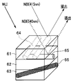
- FIG. 4 is a diagram for explaining the relationship between the WLI light and NBI light emitted from the endoscope according to the first embodiment and blood vessels in the mucous membrane of the subject
- FIG. 5 is a diagram showing the relationship between the DRI light and the subject. It is a figure for demonstrating the relationship with the blood vessel in the mucous membrane of a sample.
- WLI light white light
- blood vessels and the like existing in the mucous membrane can be reproduced on the monitor in colors that are natural for a person (doctor).
- WLI light white light
- the capillaries and mucosal fine patterns on the surface layer of the mucosa cannot always be clearly reproduced for human recognition.
- NBI Near Band Imaging
- the capillaries 64 in the mucosal surface layer 61 absorb the blue light (415 nm) in the NBI light, and as a result, the capillaries 64 are clearly visualized.
- the green light (540 nm) visualizes the blood vessels 65 in the layer 62 slightly deeper than the surface layer. As a result, the capillaries and the mucosal fine patterns on the mucosal surface layer 61 are emphasized and displayed.
- the wavelength of the NBI light which is a narrow band light, may be set to another different wavelength for special light observation.
- DRI Direct Red Imaging
- the subject is irradiated with the DRI light to obtain normal light.
- the blood vessel 66 or blood flow information from the deep mucosa layer to the submucosal layer (layer 63 in FIG. 5), which is difficult to see by observation, may be highlighted.
- fluorescence observation AFI AutoFluorescence Imaging
- the subject is irradiated with a predetermined excitation light for fluorescence observation and the neoplastic lesion and the normal mucosa are highlighted in different colors. It has become.
- the optical system 21 and the image sensor 22 can be controlled by the acquisition condition setting information.
- the exposure time of the image sensor can be changed by setting the acquisition conditions. Is. Exposure control can also eliminate the effects of saturation and low-luminance noise.
- the acquisition condition designation unit 35 sets the acquisition condition setting information for defining the display acquisition condition, which is a condition for acquiring a display image having excellent visibility (hereinafter, display acquisition condition setting information). ) And acquisition condition setting information (hereinafter referred to as analysis acquisition condition setting information) that defines the analysis acquisition condition, which is a condition for acquiring an image for analysis with excellent analyst in image analysis processing, are mixed. It may be generated by letting it occur. For example, only the display acquisition condition setting information may be output in the predetermined first period, and the display acquisition condition setting information and the analysis acquisition condition setting information may be mixed and output in the predetermined second period.
- the video processor 3 can output a display image having excellent visibility based on the display acquisition condition setting information, and the light source device 4 ( It controls at least one of the illumination unit 23), the optical system 21, the image sensor 22, and the image processing unit 12. Further, when the video processor 3 inputs the display acquisition condition setting information and the analysis acquisition condition setting information in a mixed manner, the display image having excellent visibility and the image having excellent analysis property are output. As described above, at least one of the light source device 4 (illumination unit 23), the optical system 21, the image pickup element 22, and the image processing unit 12 is controlled based on the display acquisition condition setting information and the analysis acquisition condition setting information.
- the display acquisition conditions bring the wavelength of the light source closer to natural light (daylight) so that it can be felt naturally when a doctor searches for the affected area with natural light or illuminates the affected area (mainly the surface) for observation.
- This is an imaging and lighting condition for performing image processing that emphasizes visibility on the imaging result and setting the frame rate and the like with an emphasis on continuity.
- the acquisition conditions for analysis are imaging and lighting conditions that increase the amount of effective information for image judgment rather than the visibility of the doctor, and the wavelength of the light source is assumed to reach not only the surface of the affected area but also the inside of the affected area.
- image processing that emphasizes the amount of effective information for analysis is performed, and the frame rate and the like are set with an emphasis on analyticity so that it is easier to determine specific patterns and image features rather than continuity.
- 6 to 8 show an image captured by the video processor 3 and output to the monitor 5 when the display acquisition condition setting information and the analysis acquisition condition setting information are mixed and input to the video processor 3. It is explanatory drawing which shows an example of the image or the image supplied to the image analysis unit 32.
- FIG. 6 shows a series of frames obtained by imaging the image sensor 22.
- WLI ⁇ Raw> indicates a captured image having a high frame rate (for example, 30 FPS or more) obtained by imaging using a high amount of WLI light as illumination light.
- NBI ⁇ Raw> in FIG. 6 shows an image captured at a low frame rate (for example, about 1 FPS) obtained by imaging (narrow band imaging) using NBI light as illumination light.
- the low light amount WLI ⁇ Raw> indicates a low frame rate (for example, 1 FPS) captured image obtained by imaging using a low light amount WLI light as illumination light.
- the WLI ⁇ Raw> frame is used to generate a display image.
- the NBI ⁇ Raw> frame and the low light amount WLI ⁇ Raw> frame are used to generate an image for analysis.
- the WLI ⁇ Raw> frame may be used to generate an image for analysis.
- a DRI ⁇ Raw> frame obtained by imaging using DRI light as illumination light is acquired at a low frame rate (about 1 FPS) as an image to be captured for image analysis.
- a low frame rate about 1 FPS
- an image captured by the excitation light for AFI observation may be acquired. In this way, since the conditions for acquiring the imaged result are changed at the same position where the object is imaged, useful information can be acquired with a simple configuration without complicated operations.
- a display image having excellent visibility can be obtained from an image captured at a high frame rate (for example, 30 FPS or more) obtained by imaging using a high amount of WLI light as illumination light.
- the light source setting conditions, the optical system setting conditions, the imaging setting conditions, and the like for obtaining such an image are the display acquisition conditions.
- an image obtained by observing special light such as an NBI ⁇ Raw> frame
- an image having excellent analyzability of image analysis can be obtained, and a light source for obtaining such an image.
- the setting conditions of the above, the setting conditions of the optical system, the setting conditions of imaging, and the like are the acquisition conditions for analysis.
- the image processing condition for obtaining an image having excellent visibility is a display acquisition condition
- the image processing condition for obtaining an image having excellent analyst property is an analysis acquisition condition.
- FIG. 9 is a chart showing specific examples of display acquisition conditions and analysis acquisition conditions regarding image processing, and is for explaining an example of conditions that can be realized by image processing of the image processing unit 12.
- the video processor 3 performs gamma processing according to the characteristics of the human eye in accordance with display acquisition conditions with respect to gamma processing among image processing performed on an imaging signal. Further, the video processor 3 does not perform gamma processing unnecessary for the analysis processing according to the acquisition conditions for analysis.
- the video processor 3 obtains a display image as shown in FIG. 9 with respect to other image processing such as white balance, color correction, noise reduction, and image enhancement. Distinguish between image processing for obtaining an image for analysis and image processing for obtaining an image for analysis.
- the image processing unit 12 of the video processor 3 acquires a WLI image for display having excellent visibility from the captured image of WLI ⁇ Raw> by performing signal processing according to the display acquisition condition setting information.
- the navigation device 30 outputs the WLI image having excellent visibility to the monitor 5 as a display image.
- FIG. 7 shows this, and the control unit 31 of the navigation device 30 extracts the WLI image from the images output from the video processor 3 and outputs it to the monitor 5.
- the WLI image obtained by the image processing for WLI ⁇ Raw> is extracted and supplied to the monitor 5 from the series of frames of FIG.
- the image is taken so that the frame rate of the WLI image supplied to the monitor 5 is, for example, 30 FPS or more. Since the operation is performed by looking at the image for visual confirmation, the image frame is eliminated as much as possible per hour, but this is not the case, for example, if the image does not change.
- the captured image obtained by the imaging device 20 of the endoscope 2 is displayed on the display screen of the monitor 5.
- the image displayed on the monitor 5 is a WLI image having excellent visibility, and the operator can confirm the image in the visual field range of the imaging device 20 as an easy-to-see image on the display screen of the monitor 5.
- the WLI image with excellent visibility may lack useful information for image analysis for navigation due to signal processing in the image processing unit 12. Therefore, as shown in FIG. 9, the video processor 3 stops a lot of image processing on the image for analysis according to the acquisition condition for analysis, and adds information useful for image analysis. In this way, the analysis acquisition condition setting information makes it possible to output an analysis image useful for image analysis.
- the control unit 31 gives all the output images of the video processor 3 including the NBI image to the image analysis unit 32 to perform image analysis.
- FIG. 8 shows an image supplied to the image analysis unit 32.
- the control unit 31 may provide the image analysis unit 32 with only the images excluding the WLI image among the output images of the video processor 3.
- the image analysis unit 32 performs various image analysis to support the surgeon.
- the image analysis unit 32 performs image analysis on the captured image input from the video processor 3 and obtains an image analysis result.
- the image analysis unit 32 acquires, for example, an image analysis result regarding the traveling direction of the insertion portion of the endoscope 2 or an image analysis result regarding the discrimination result of the lesion portion.
- the image analysis result of the image analysis unit 32 is given to the support information generation unit 36.
- the support information generation unit 36 generates support information based on the image analysis result of the image analysis unit 32. For example, when the support information generation unit 36 obtains a direction in which the insertion unit should be inserted from the image analysis result, the support information generation unit 36 generates support information indicating the insertion direction. Further, for example, when the support information generation unit 36 obtains the discrimination result of the lesion part from the image analysis result, the support information generation unit 36 generates the support information for presenting the discrimination result to the operator.
- the support information generation unit 36 may generate support display data such as an image (support image) or text (support text) to be displayed on the monitor 5 as support information. Further, the support information generation unit 36 may generate audio data for outputting audio from a speaker (not shown) as the support information.
- the navigation device 30 can change the image acquisition conditions based on the characteristics of the image used for the analysis and the image analysis result including various information acquired from the image. There is.
- the determination unit 34 determines whether or not the image acquisition condition should be changed and how the image acquisition condition should be changed. For example, when the determination unit 34 determines that a sufficient analysis result cannot be obtained or a more detailed image analysis is required based on the image analysis result, the determination unit 34 obtains the acquisition conditions necessary for performing the desired image analysis. The change is instructed to the acquisition condition designation unit 35.
- the determination unit 34 may decide to change to a specific acquisition condition based on a specific criterion. For example, the determination unit 34 may determine the acquisition condition to be changed by comparing the values included in the image analysis result such as the contrast information and the histogram information acquired from the image used for the analysis with a predetermined reference value. .. Further, the determination unit 34 may determine whether or not the image used for analysis includes a specific image feature or pattern by pattern matching or the like, and determine the acquisition condition to be set based on the result.
- the determination unit 34 instructs the acquisition condition designation unit 35 to change to the acquisition conditions necessary for obtaining the desired analysis result according to not only the image analysis result but also the observation mode and the content of the procedure. It may be.
- FIG. 10 is a flowchart for explaining the operation of the first embodiment
- FIG. 11 is an explanatory diagram for explaining an image acquired in a specific use case.
- FIG. 11 shows the same usage scene as that of FIG. 3, and shows a state in which an endoscope 2 (rigid scope) is inserted into a body cavity to observe internal tissues and organs.
- an endoscope 2 rigid scope
- the acquisition condition designation unit 35 of the navigation device 30 reads the display acquisition condition setting information in the initial setting from the acquisition condition storage unit 33 and supplies it to the video processor 3.
- the display acquisition condition setting information enables the setting of the acquisition condition for acquiring the display image
- the image pickup parameter setting unit 13 in the control unit 11 of the video processor 3 provides the display acquisition condition setting information.
- the acquisition condition I1 in FIG. 10 is, for example, an acquisition condition corresponding to the display acquisition condition setting information in the initial setting, and is a predetermined condition.
- the light source device 4 emits a high amount of WLI light from the illumination unit 23, and the control unit 11 drives the image pickup device 22 at a high frame rate (for example, 30 FPS or more), whereby the image pickup device 20 To output the captured image of WLI ⁇ Raw>.
- the image processing parameter setting unit 14 in the control unit 11 sets the image processing parameters of the image processing unit 12 based on the display acquisition condition setting information.
- the image processing unit 12 performs gamma processing, white balance processing, and human eye characteristics according to the characteristics of the human eye with respect to the image captured from the image pickup device 20.
- a WLI image suitable for display is generated.
- the WLI image acquired by the image processing unit 12 is supplied to the navigation device 30.
- the control unit 31 outputs the input WLI image as a display image to the monitor 5. In this way, a WLI image having excellent visibility is displayed on the display screen of the monitor 5. The surgeon can surely observe the internal tissues and organs in the body cavity by the WLI image having good visibility on the display screen of the monitor 5.
- the control unit 31 determines in step S2 whether or not the specific timing for changing from the acquisition condition I1 to the acquisition condition I2 has come.
- Support by the navigation device 30 is not always required for the entire period from the start to the end of surgery or examination. Considering the amount of image analysis processed by the navigation device 30, it is considered preferable to provide support by the navigation device 30 only when support is required. Therefore, the control unit 31 sets the transition timing from the acquisition condition I1 based on the display acquisition condition setting information to the acquisition condition I2 including the analysis acquisition condition setting information when instructed by the surgeon or in a predetermined medical scene. It is determined that it has been reached and switched.
- Acquisition condition I2 is a predetermined condition. The acquisition conditions I1 and I2 can be set to appropriate contents by user settings.
- control unit 31 determines that the specific timing has been reached according to the operation of the operator, for example, the process proceeds to step S3, and the acquisition condition designation unit 35 is instructed to shift to the acquisition condition I2.
- the control unit 31 shifts the process to step S4.
- step S3 the acquisition condition designation unit 35 reads the acquisition condition setting information including the display acquisition condition setting information and the analysis acquisition condition setting information and outputs the acquisition condition setting information to the video processor 3 to shift to the acquisition condition I2. That is, the acquisition condition I2 is a condition for acquiring not only the display image but also the analysis image by using the display acquisition condition setting information and the analysis acquisition condition setting information.
- the light source device 4, the optical system 21, and the image sensor 22 are controlled by the image pickup parameter setting unit 13 and the image processing parameter setting unit 14, and acquire WLI ⁇ Raw> at a frame rate of, for example, 30 FPS or more.
- an image suitable for image analysis is acquired.
- the image pickup apparatus 20 repeatedly acquires WLI ⁇ Raw>, WLI ⁇ Raw>, NBI ⁇ Raw>, WLI ⁇ Raw>, low light amount WLI ⁇ Raw>, and WLI ⁇ Raw> frames. ..
- FIG. 11 In the example of FIG.
- the image processing parameter setting unit 14 controls the image processing unit 12 based on the display acquisition condition setting information and the analysis acquisition condition setting information. As a result, the image processing unit 12 acquires the WLI image by performing signal processing on the WLI ⁇ Raw> frame based on the display acquisition condition setting information. Further, the image processing unit 12 does not perform signal processing for display, for example, on the NBI ⁇ Raw> and low light amount WLI ⁇ Raw> frames based on the analysis acquisition condition setting information. The image processing unit 12 converts the NBI ⁇ Raw> frame and the low light amount WLI ⁇ Raw> frame into an NBI image and a low light amount WLI image, respectively. The image processing unit 12 outputs these images to the navigation device 30.
- the control unit 31 of the navigation device 30 outputs the WLI image as a display image to the monitor 5, and outputs the NBI image and the low light amount WLI image to the image analysis unit 32.
- the WLI image is also given to the image analysis unit 32.
- the image analysis unit 32 performs image analysis using the WLI image, the NBI image, and the low light amount WLI image, and obtains a predetermined analysis result. For example, in the case of providing diagnostic support, the image analysis unit 32 can obtain desired analysis results such as the presence / absence of a lesion candidate and the discrimination of a lesion.
- the image analyzed by the image analysis unit 32 includes an image obtained by special light observation such as an NBI image suitable for analysis, and is not subjected to image processing accompanied by lack of information. It has a sufficient amount of information for analysis, and the image analysis unit 32 can obtain a highly accurate analysis result.
- This amount of information is the information that each pixel has to derive something from the image, and changes in the arrangement of pixels are noticeable, such as contrast, spatial frequency, gradation characteristics, color changes, and their changes.
- the amount of information required to identify the characteristics of the object of each image to be analyzed, such as the distinctiveness of wavelength differences, is assumed.
- step S4 and the determination of step S5 are performed after step S2 or S3, but in the case of NO determination in step S5, the process shifts to step S7.
- step S7 it is determined whether or not the support display is necessary. For example, when a lesion candidate is found based on the image analysis result of the image analysis unit 32, the control unit 31 determines that support display is necessary and causes the support information generation unit 36 to generate support information. .. The support information generation unit 36 generates support information based on the analysis result of the image analysis unit 32.
- the support information generation unit 36 puts a mark (support display) indicating the position of the lesion candidate on the display image displayed on the display screen of the monitor 5 as support information when the lesion candidate is found.
- Display data for display may be generated.
- the control unit 31 gives the display data generated by the support information generation unit 36 to the monitor 5. In this way, a mark indicating the position of the lesion candidate is displayed on the display image (observed image by the endoscope 2) displayed on the monitor 5 (step S8).
- the WLI image having excellent visibility is displayed on the monitor 5, so that the affected part or the like can be easily confirmed, and the NBI image or the like suitable for image analysis is used for support. It is possible to obtain highly accurate analysis results and provide extremely effective support for the surgeon.
- the image for analysis is acquired only when support is required, which enables high-quality display without unnecessarily reducing the frame rate of the display image and the processing of image analysis. It is possible to prevent the amount from increasing unnecessarily.
- these display images and analysis images are acquired based on the image pickup signal of the image pickup device 20, and it is not necessary to arrange a plurality of image pickup devices at the tip end portion of the endoscope insertion portion. There is no need for high-performance hardware because the amount of information processing to be processed is significantly increased.
- step S4 the determination unit 34 acquires whether or not the acquisition conditions should be changed in order to acquire the analysis result with higher accuracy based on the analysis image and the image analysis result of the image analysis unit 32. Judge the conditions.
- the determination unit 34 determines whether or not an analysis result with even higher accuracy can be obtained (step S5), and if it is obtained, causes the acquisition condition designation unit 35 to set the acquisition condition I3 for that purpose (step S6). ). If the determination unit 34 determines that it is not possible to obtain an analysis result with even higher accuracy, the determination unit 34 shifts the process to step S7.
- step S6 the acquisition condition designation unit 35 reads out the display acquisition condition setting information and the analysis acquisition condition setting information from the acquisition condition storage unit 33 according to the determination result of the determination unit 34, and sets the acquisition condition I3 as the image pickup parameter setting unit 13. And output to the image processing parameter setting unit 14. That is, the acquisition condition I3, which is adaptively changed according to the output of the video processor 3, is fed back to the video processor 3.
- the acquisition condition designation unit 35 generates and outputs display acquisition condition setting information and analysis acquisition condition setting information according to the determination result of the determination unit 34, not the information stored in the acquisition condition storage unit 33. May be good.
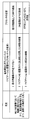
- FIG. 12 is a chart for explaining an example of the acquisition condition I3 based on the determination by the determination unit 34.
- the status column of FIG. 12 shows the information obtained from the analysis result of the image analysis unit 32, and the feedback content shows the acquisition condition I3 specified by the acquisition condition designation unit 35 based on the determination result of the determination unit 34.
- the image analysis unit 32 can perform image analysis using this display image (WLI image).
- the determination unit 34 shifts from step S2 to step S4, the determination unit 34 makes a determination using the analysis result of the WLI image of the image analysis unit 32.
- the image analysis unit 32 shall obtain blood vessel information related to the mucous membrane from the analysis result for the WLI image.
- the determination unit 34 determines that many blood vessels can be seen on the surface layer of the mucous membrane, it acquires an image for analysis such as an NBI image using long wavelength illumination light as acquisition condition I3. Set the conditions.
- the display image (short wavelength image) using the short wavelength illumination light makes it easy to confirm the microvessels on the surface of the tissue. Therefore, when many microvessels are visible, it is determined that some malignant tumor may be lurking based on the blood vessel information in the mucosal surface layer, and the microvascular structure in the mucosal surface layer can be grasped more clearly.
- the acquisition condition I3 for acquiring the NBI image or the like as the analysis image is set.
- the determination unit 34 determines that the microblood vessels of the submucosal surface layer portion are based on the analysis result based on the analysis image.
- a DRI image by DRI special light observation with a short wavelength is acquired so that blood vessel information in the deeper part of the mucosa (for example, blood vessel information in the submucosal layer from the deeper layer of the mucosa) can be obtained.
- the acquisition information I3 for this is set.
- the determination unit 34 increases or decreases the frame rate of the display image according to the magnitude of the movement of the image of the subject affected portion in the image analyzed by the image analysis unit 32, and the type of the image of the analysis image.
- the acquired information I3 for increasing / decreasing is set.
- the determination unit 34 sets the acquired information I3 for changing the brightness of the image for analysis according to the brightness information around the affected part of the subject in the image analyzed by the image analysis unit 32. For example, when the image around the affected area of the subject is dark, the acquired information I3 for brightening the brightness of the image for analysis is set, and when the image around the affected area of the subject is bright, the brightness of the image for analysis is set. The acquired information I3 for darkening the image is set. It should be noted that such control can be performed by appropriately modifying the amount of light of the light source, the exposure time of the image sensor, and the like. In this way, the support display in step S8 is performed using the image acquired based on the acquisition condition I3.
- the determination unit 34 is designed to repeatedly change the setting contents of the acquisition condition I3 as necessary. May be good.
- the display acquisition condition setting information for acquiring the display image in the predetermined first period is output, and for example, in the predetermined second period corresponding to the operation of the operator or the like.
- An example of acquiring a display image and an analysis image by mixing the display acquisition condition setting information and the analysis acquisition condition setting information has been described.
- the surgeon sets the first period in the process of moving the insertion portion of the endoscope 2 to the observation target site, and detects the lesion candidate after the tip of the endoscope 2 reaches the observation target site.
- the second period may be set at the time of starting.
- the acquisition condition I1 is first shown as an example of being generated using only the display acquisition condition setting information for acquiring the display image, but after the power is turned on, the display acquisition condition and the analysis acquisition condition May be set at all times.
- the acquisition condition I1 it is set so that one, for example, NBI ⁇ Raw> frame is acquired for every predetermined number of WLI ⁇ Raw> frames, and the WLI image based on WLI ⁇ Raw> is used as the display image.
- WLI image and NBI image based on NBI ⁇ Raw> may be used as an image for analysis.
- a high-quality image can be displayed by a WLI image having a relatively high frame rate, and analysis necessary for support can be performed with the processing load of the navigation device 30 sufficiently reduced. It is possible. Then, by setting the acquisition condition I2 in which the acquisition rate of the analysis image is increased based on the analysis result or by the operation of the operator, high-precision analysis according to the support requested by the operator is performed. Is possible.
- FIG. 13 is an explanatory diagram for explaining the support display.
- FIG. 13 shows a state in which the endoscope 2 is inserted into the body cavity P to observe internal tissues and organs, and the arrows indicate the illumination light emitted from the tip of the rigid mirror and the reflected light thereof. , The reflected light is incident on the imaging device 20 of the endoscope 2.
- the display image (Im1) obtained under the acquisition condition I1 is obtained by observing white light, and is close to the result seen in natural light that humans are accustomed to. That is, in this example, the acquisition condition I1 is a condition for obtaining a display image with an emphasis on visibility.
- the acquisition condition I1 is a condition for obtaining a display image with an emphasis on visibility.
- the reflected component from the surface of the object is superior and the information inside the tissue is relatively reduced. Therefore, even if there is some abnormality in the part surrounded by the broken line, it cannot be found. It can be difficult.
- Image for analysis under acquisition condition I2 Since the image for analysis under the acquisition condition I2 is an image (Im2) acquired under the imaging condition and the image processing condition including the observation light condition that enables the inside of the tissue to be observed, the change inside the tissue that does not appear on the surface of the body tissue. Can be detected.
- FIG. 13 shows the lesions detected in the image by hatching.
- the analysis image under the acquisition condition I3 is an image (Im3) obtained by using the acquisition condition changed from the acquisition condition I2 in order to obtain a more accurate analysis result.
- the shape of the lesion is clearer than that of the image Im2.
- the analysis result using the image (Im3) is often more accurate than the analysis result using the image (Im2).
- the support information generation unit 36 generates support information based on a more accurate analysis result.
- the support information is display data indicating the shape of the lesion.
- the control unit 31 superimposes and displays the display based on the support information on the display image (Im1).
- the support information generation unit 36 may generate display data as support information for displaying a text display such as "find a lesion" in the vicinity of the position of the broken line portion. In this way, the observer can confirm the display indicating the presence of the lesion portion detected by the image analysis unit 32 on the display image that is natural to the human eye, and the observer can use this portion in another method. It is also possible to take measures such as re-examination at.
- the support display method by the support information generation unit 36 can be improved and customized in various ways. For example, in FIG. 13, an example of displaying the support display based on the analysis image based on the acquisition condition I3 has been described, but the support display based on the analysis image based on the acquisition condition I2 may be displayed. Further, the support information generation unit 36 may display the analysis image as it is or display the composite image based on the analysis result as the support display.
- the determination unit 34 may need to consider a plurality of requests (acquisition conditions) when changing the acquisition conditions according to the situation.
- FIG. 14 is a chart for explaining the priority for such a plurality of requests.
- the peripheral image is dark, and the movement on the image is large.
- the determination unit 34 obtains a bright image such as a DRI image using a long wavelength as the analysis image without lowering the frame rate of the display image.
- the acquisition condition I3 for enabling is generated.
- the determination unit 34 prioritizes each request (condition) and determines the acquisition condition I3. For example, the determination unit 34 has a priority of 1 on the condition that the frame rate of the display image is not lowered. Further, the determination unit 34 is required to acquire a DRI image or the like using a long wavelength as an analysis image as the priority order 2. Further, the determination unit 34 is subject to the condition that a bright image is acquired as the priority order 3.
- the determination unit 34 instructs the acquisition condition designation unit 35 to generate the acquisition condition I3 in consideration of such a priority.
- the acquisition condition designation unit 35 generates display acquisition condition setting information for maintaining the frame rate of the WLI ⁇ Raw> frame used as the display image at 30 FPS or more.
- the acquisition condition designation unit 35 generates analysis acquisition condition setting information for acquiring a DRI image by a DRI ⁇ Raw> frame for generating a DRI image which is an analysis image in 2 FPS.
- the acquisition condition designation unit 35 does not support the request of priority 3 in consideration of the limitation of the maximum frame rate that can be imaged.
- the video processor 3 can efficiently acquire images useful for both display and analysis.
- various types of endoscopes and video processors having different performances and functions can reliably acquire images according to acquisition conditions.
- FIG. 1 shows an example in which the video processor 3 and the navigation device 30 are separately configured, it is clear that the navigation device 30 may be configured to be built in the video processor 3.
- the endoscopic system is not limited to the laparoscopic surgery system, and may be applied to an endoscopic system using a normal flexible endoscope.
- the analysis of the image analysis unit 32, the determination of the determination unit 34, the generation of the acquisition condition setting information of the acquisition condition designation unit 35, and the like in the navigation device 30 may be realized by the AI (artificial intelligence) device.
- FIG. 15 is a flowchart showing an operation flow adopted in the second embodiment.
- the hardware configuration in this embodiment is the same as that in FIG. 1, and the description thereof will be omitted.
- the present embodiment determines which of these analysis results has higher accuracy when the acquisition condition I1 is changed to the acquisition condition I2. It should be noted that the higher accuracy of the analysis result means that a more suitable analysis result can be obtained for support as described above, for example, when the amount of information obtained from the image increases. including.
- the present embodiment when it is determined that a more accurate analysis result can be obtained by changing the conditions, further changes of the same type as the changed contents of the acquisition conditions are made, and if not, the acquisition conditions are obtained. It is possible to set the optimum acquisition conditions by making changes of a type different from the changes made in.
- Further changes of the same type as the changes in the acquisition conditions include, for example, when the acquisition condition I1 for acquiring a normal light observation image is changed to the acquisition condition I2 for acquiring an NBI image, the wavelength of the NBI light. It is a change that changes. Further, the change of the type different from the change content of the acquisition condition is, for example, when the acquisition condition I1 for acquiring the normal light observation image is changed to the acquisition condition I2 for acquiring the NBI image, the change is changed to the NBI image. Instead, it means changing the acquisition conditions for acquiring the DRI image.
- the acquisition condition storage unit 33 has an acquisition condition I3 when a more accurate analysis result is obtained for the combination of the acquisition conditions I1 and I2, and an acquisition condition I3 when the accuracy of the analysis result is lowered. May be registered in advance.
- the determination unit 34 can read any of the stored contents of the acquisition condition storage unit 33 into the acquisition condition designation unit 35 according to the determination result of whether the analysis result has become high accuracy or the accuracy has decreased. It may be instructed whether to do it.
- step S11 of FIG. 15 the image is captured based on the predetermined acquisition condition I1.
- the image is acquired by the endoscope 2 under the control of the control unit 11 of the video processor 3, and the captured image is captured via the navigation device 30. Is supplied to the monitor 5.
- the acquisition condition I1 for example, it is assumed that the display acquisition condition setting information is adopted and the WLI ⁇ Raw> frame is acquired.
- the image processing unit 12 outputs a WLI image based on the WLI ⁇ Raw> frame to the navigation device 30, and the control unit 31 supplies the WLI image to the monitor 5 and displays it on the screen. In this way, a WLI image having excellent visibility is displayed on the display screen of the monitor 5.
- the video processor 3 provisionally records the WLI image acquired based on the acquisition condition I1 as the captured image Im1 on a recording device (not shown) (step S12). Further, the image analysis unit 32 of the navigation device 30 obtains an analysis result by image analysis of the WLI image acquired based on the acquisition condition I1.
- the control unit 31 determines in step S13 whether or not there is an instruction to change the acquisition condition. Similar to the first embodiment, for example, it is possible to generate an instruction to change the acquisition condition according to the instruction of the operator, and the determination unit 34 determines the acquisition condition based on the analysis result of the image analysis unit 32. It is also possible to generate a change instruction.
- the control unit 31 causes the acquisition condition designation unit 35 to generate a predetermined acquisition condition I2.
- the acquisition condition designation unit 35 may read the information of the acquisition condition I2 from the acquisition condition storage unit 33.
- the acquisition condition I2 is a condition for acquiring a WLI image having a predetermined frame rate or higher and, for example, an NBI image.
- the acquisition condition I2 is a condition for acquiring a WLI image having a predetermined frame rate or higher and, for example, an NBI image.
- an acquired image including the WLI ⁇ Raw> frame and the NBI ⁇ Raw> frame is acquired by the endoscope 2 (step S14).
- the image processing unit 12 generates a WLI image and an NBI image based on the image captured by the image pickup device 20, and outputs the WLI image and the NBI image to the navigation device 30.
- the image analysis unit 32 obtains an analysis result by image analysis of the WLI image and the NBI image acquired based on the acquisition condition I2.
- the support information generation unit 36 generates support information based on the analysis result.
- the video processor 3 provisionally records the WLI image and the NBI image acquired based on the acquisition condition I2 as the captured image Im2 on a recording device (not shown) (step S15).
- step S16 the determination unit 34 determines whether or not an image based on the acquisition conditions I1 and I2 has been acquired for the same observation site. For example, the determination unit 34 can determine whether or not the image is based on the same observation site based on the analysis result of the image analysis unit 32.
- the determination unit 34 determines that each image based on the acquisition conditions I1 and I2 is for the same observation site, in the next step S17, the amount of information (hereinafter, the part described as the amount of information is something). It is determined whether or not the amount of information representing the characteristics of the object included in the image to be used for support and assistance has increased. That is, the determination unit 34 irradiates the same region with the amount of information of the image Im1 based on the acquisition condition I1 obtained by irradiating a certain region of the subject with WLI light and NBI light. The amount of information of the image Im2 based on the acquisition condition I2 obtained by the above is compared with the amount of information. The determination unit 34 provides relative information between the amount of information of the image Im1 (the amount of information required to obtain effective support) and the amount of information of the image Im2 (the amount of information required to obtain effective support). It is determined which is the image with a large amount.
- the determination unit 34 determines that a more effective image can be acquired by the same type of acquisition condition.
- the acquisition condition designation unit 35 is instructed to set the same type of acquisition condition I3.
- the part described as the image condition of the same type of change content does not need to be further changed such as image acquisition and processing when an image with a sufficient amount of information is obtained.
- the acquisition condition designation unit 35 changes the information for acquiring an image by NBI light in a wavelength band different from the wavelength band specified in the acquisition condition I2 as the acquisition condition I3 of the same type as the acquisition condition I2, for example.
- the endoscope 2 acquires an acquired image including a WLI ⁇ Raw> frame having a predetermined frame rate or higher and an NBI ⁇ Raw> frame based on NBI light having a wavelength different from the previous one.
- the image processing unit 12 generates a WLI image and an NBI image based on the image captured by the image pickup device 20, and outputs the WLI image and the NBI image to the navigation device 30.
- the image analysis unit 32 obtains an analysis result by image analysis of the WLI image and the NBI image acquired based on the acquisition condition I2.
- the support information generation unit 36 generates support information based on the analysis result.
- the video processor 3 provisionally records the WLI image and the NBI image acquired based on the acquisition condition I3 as the captured image Im3 on a recording device (not shown) (step S19).
- step S17 if it is determined in step S17 that the amount of information has not increased, the determination unit 34 shifts the process to step S20 and determines whether or not the amount of information has decreased. That is, the determination unit 34 irradiates the same region with WLI light and NBI light rather than the amount of information of the image Im1 based on the acquisition condition I1 obtained by irradiating a certain region of the subject with WLI light. It is determined whether or not the amount of information of the image Im2 based on the acquisition condition I2 obtained by the above is reduced.
- the determination unit 34 can acquire an effective image under acquisition conditions different from those of the acquisition condition I2.
- the acquisition condition designation unit 35 is instructed to set different types of acquisition conditions I3.
- the acquisition condition designation unit 35 changes the acquisition condition I2 and the acquisition condition I3 different from the acquisition condition I2 to the information for acquiring the image by the DRI light instead of the NBI light specified in the acquisition condition I2.
- the acquisition condition designation unit 35 includes NBI light in a wavelength band different from the wavelength band of the NBI light specified by the acquisition condition I2 as the acquisition condition I3 different from the acquisition condition I2, and includes DRI light and AFI light.
- the conditions for acquiring the used image may be changed.
- the acquisition condition designation unit 35 may be accompanied by a change in the frame rate of the image sensor 22 or a change in various image processing by the image processing unit 12.
- the image analysis unit 32 obtains an analysis result by image analysis for each image acquired based on the acquisition condition I2 and the heterogeneous acquisition condition I3.
- the support information generation unit 36 generates support information based on the analysis result. Further, the video processor 3 provisionally records each image acquired based on the acquisition condition I2 and the acquisition condition I3 of a different type as the image Im4 on a recording device (not shown) (step S22).
- control unit 31 determines NO in steps S16 and S20 or the process of step S22 is completed, the control unit 31 proceeds to the next step S23, and the images acquired based on the acquisition conditions I1 to I3 are the same observation site.
- the display by the support information from the support information generation unit 36 based on the image analysis results of the images Im2 to Im4 is superimposed and displayed on the image Im1 displayed on the monitor 5.
- FIG. 15 shows an example in which the acquisition condition I3 in steps S18 and S21 is set only once in any of the steps, but step S16 until the amount of information does not increase or decrease.
- ⁇ S22 may be repeatedly executed. However, such repetition can be very time consuming and cannot be determined quickly, so it may be terminated in a particular situation. Of the two conditions, the better one may be used.
- FIG. 16 is a block diagram showing a third embodiment.
- the endoscope system according to the third embodiment includes, for example, a system using an examination endoscope such as a colonoscope, a system using a surgical endoscope such as a laparoscope, and the like. Many endoscopic systems can be applied, but in FIG. 16, the endoscopic system 1 assuming a laparoscopic surgery system is illustrated.
- an endoscope 2 (laparoscope) that images the inside of the body cavity of the subject P and outputs an imaging signal is connected to the endoscope 2 to control the drive of the endoscope 2 and control the drive of the endoscope 2.
- a video processor 3 that acquires an imaging signal related to a subject imaged by the endoscope 2 and performs predetermined image processing on the imaging signal, and a predetermined image processor 3 that is internally installed in the video processor 3 to irradiate the subject.
- a light source device 4 for supplying the illumination light of the above, a monitor 5 for displaying an observation image according to an imaging signal, and a navigation device 30 connected to a video processor 3 are mainly provided, but an inspection endoscope is used.
- the type of endoscope 2 is different in the system, the other components are the same as those shown in FIG.
- each component in the endoscope system 1 of the third embodiment that is, each configuration of the endoscope 2, the video processor 3, the light source device 4, the monitor (display) 5, and the navigation device 30, is the first. Since it is the same as the embodiment of the above, detailed description here will be omitted.
- the navigation device 30 outputs an image in which the lesion site is marked with high accuracy to the monitor (display) 5. It has become like.
- each image information (display) without omission provided by the video processor 3 as described above is provided.
- image information for analysis + image information for analysis for example, an image in which a region considered to be a lesion site is marked with high accuracy is output to the monitor (display) 5 and provided to the operator as navigation information.
- the navigation device 30 outputs an image presenting useful information for the procedure to the monitor (display) 5.
- image information + image information for analysis for example, information such as the position of the tumor, the excision area, and the position of the main blood vessel is output to the monitor (display) 5 and provided to the operator as navigation information.
- the present invention provides image information provided from the video processor 3 to the navigation device 30 as described above in the endoscope system 1 using various endoscopes.
- the image information for analysis for the navigation device 30 is prepared, and the navigation device 30 performs the recognition process using the image information without any omissions.
- Useful navigation information can be provided to the surgeon.
- the endoscope system for examination and the endoscope system for surgery are given as examples, but the third embodiment is not limited to this.
- the endoscopic system according to the embodiment may be applied to an endoscopic system using another type of endoscope.
- the controls and functions mainly described in the flowchart can be set by a program, and the above-mentioned controls and functions can be realized by reading and executing the program by a computer.
- the program may record or store all or part of it on a portable medium such as a flexible disk, a CD-ROM, or a non-volatile memory, or a storage medium such as a hard disk or a volatile memory. It can be distributed or provided at the time of product shipment or via a portable medium or communication line.
- the user can easily realize the image processing device of the present embodiment by downloading the program via a communication network and installing it on a computer, or installing it on a computer from a recording medium. can.
- the present invention is not limited to each of the above embodiments as it is, and at the implementation stage, the components can be modified and embodied within a range that does not deviate from the gist thereof.
- various inventions can be formed by an appropriate combination of the plurality of components disclosed in each of the above embodiments. For example, some components of all the components shown in the embodiment may be deleted. In addition, components across different embodiments may be combined as appropriate.
- a navigation device is a device that detects an abnormality in the fields of industry and security as well as the medical field, and support information can be rewritten as information that encourages awareness.
Landscapes
- Health & Medical Sciences (AREA)
- Life Sciences & Earth Sciences (AREA)
- Surgery (AREA)
- Engineering & Computer Science (AREA)
- Radiology & Medical Imaging (AREA)
- General Health & Medical Sciences (AREA)
- Physics & Mathematics (AREA)
- Medical Informatics (AREA)
- Nuclear Medicine, Radiotherapy & Molecular Imaging (AREA)
- Heart & Thoracic Surgery (AREA)
- Veterinary Medicine (AREA)
- Biomedical Technology (AREA)
- Optics & Photonics (AREA)
- Biophysics (AREA)
- Molecular Biology (AREA)
- Animal Behavior & Ethology (AREA)
- Pathology (AREA)
- Public Health (AREA)
- Signal Processing (AREA)
- Quality & Reliability (AREA)
- Computer Vision & Pattern Recognition (AREA)
- General Physics & Mathematics (AREA)
- Theoretical Computer Science (AREA)
- Endoscopes (AREA)
Abstract
L'invention concerne un dispositif de traitement d'image comprenant : une unité de spécification de conditions d'acquisition pour définir, pour une unité d'acquisition d'image, des premières conditions d'acquisition qui comprennent des conditions d'acquisition d'affichage pour acquérir une image d'affichage et des secondes conditions d'acquisition qui comprennent les conditions d'acquisition d'affichage et des conditions d'acquisition d'analyse pour acquérir une image pour une analyse d'image, une première image étant acquise sur la base des conditions d'acquisition d'affichage et une seconde image étant acquise sur la base des conditions d'acquisition d'analyse ; une unité d'analyse d'image pour soumettre une image acquise par l'unité d'acquisition d'image à une analyse ; une unité de génération d'informations de support pour générer des informations de support sur la base des résultats d'analyse d'image provenant de l'unité d'analyse d'image ; et une unité de commande pour commander la permutation entre les premières conditions d'acquisition et les secondes conditions d'acquisition.
Priority Applications (4)
| Application Number | Priority Date | Filing Date | Title |
|---|---|---|---|
| CN202080098836.3A CN115315210A (zh) | 2020-04-09 | 2020-04-09 | 图像处理装置、图像处理方法、导航方法以及内窥镜系统 |
| JP2022513820A JPWO2021205624A1 (fr) | 2020-04-09 | 2020-04-09 | |
| PCT/JP2020/016037 WO2021205624A1 (fr) | 2020-04-09 | 2020-04-09 | Dispositif de traitement d'image, procédé de traitement d'image, procédé de navigation et système d'endoscope |
| US17/960,983 US20230039047A1 (en) | 2020-04-09 | 2022-10-06 | Image processing apparatus, image processing method, navigation method and endoscope system |
Applications Claiming Priority (1)
| Application Number | Priority Date | Filing Date | Title |
|---|---|---|---|
| PCT/JP2020/016037 WO2021205624A1 (fr) | 2020-04-09 | 2020-04-09 | Dispositif de traitement d'image, procédé de traitement d'image, procédé de navigation et système d'endoscope |
Related Child Applications (1)
| Application Number | Title | Priority Date | Filing Date |
|---|---|---|---|
| US17/960,983 Continuation US20230039047A1 (en) | 2020-04-09 | 2022-10-06 | Image processing apparatus, image processing method, navigation method and endoscope system |
Publications (1)
| Publication Number | Publication Date |
|---|---|
| WO2021205624A1 true WO2021205624A1 (fr) | 2021-10-14 |
Family
ID=78023126
Family Applications (1)
| Application Number | Title | Priority Date | Filing Date |
|---|---|---|---|
| PCT/JP2020/016037 WO2021205624A1 (fr) | 2020-04-09 | 2020-04-09 | Dispositif de traitement d'image, procédé de traitement d'image, procédé de navigation et système d'endoscope |
Country Status (4)
| Country | Link |
|---|---|
| US (1) | US20230039047A1 (fr) |
| JP (1) | JPWO2021205624A1 (fr) |
| CN (1) | CN115315210A (fr) |
| WO (1) | WO2021205624A1 (fr) |
Families Citing this family (1)
| Publication number | Priority date | Publication date | Assignee | Title |
|---|---|---|---|---|
| JP2023018543A (ja) * | 2021-07-27 | 2023-02-08 | 富士フイルム株式会社 | 内視鏡システム及びその作動方法 |
Citations (2)
| Publication number | Priority date | Publication date | Assignee | Title |
|---|---|---|---|---|
| WO2018163644A1 (fr) * | 2017-03-07 | 2018-09-13 | ソニー株式会社 | Dispositif de traitement d'informations, système d'assistance et procédé de traitement d'informations |
| JP2019042156A (ja) * | 2017-09-01 | 2019-03-22 | 富士フイルム株式会社 | 医療画像処理装置、内視鏡装置、診断支援装置、及び、医療業務支援装置 |
-
2020
- 2020-04-09 CN CN202080098836.3A patent/CN115315210A/zh active Pending
- 2020-04-09 WO PCT/JP2020/016037 patent/WO2021205624A1/fr active Application Filing
- 2020-04-09 JP JP2022513820A patent/JPWO2021205624A1/ja active Pending
-
2022
- 2022-10-06 US US17/960,983 patent/US20230039047A1/en active Pending
Patent Citations (2)
| Publication number | Priority date | Publication date | Assignee | Title |
|---|---|---|---|---|
| WO2018163644A1 (fr) * | 2017-03-07 | 2018-09-13 | ソニー株式会社 | Dispositif de traitement d'informations, système d'assistance et procédé de traitement d'informations |
| JP2019042156A (ja) * | 2017-09-01 | 2019-03-22 | 富士フイルム株式会社 | 医療画像処理装置、内視鏡装置、診断支援装置、及び、医療業務支援装置 |
Also Published As
| Publication number | Publication date |
|---|---|
| US20230039047A1 (en) | 2023-02-09 |
| JPWO2021205624A1 (fr) | 2021-10-14 |
| CN115315210A (zh) | 2022-11-08 |
Similar Documents
| Publication | Publication Date | Title |
|---|---|---|
| WO2018034075A1 (fr) | Système d'imagerie | |
| RU2391894C2 (ru) | Устройство для считывания изображения живого организма и система формирования изображения живого организма | |
| JP7074065B2 (ja) | 医療用画像処理装置、医療用画像処理方法、プログラム | |
| JPWO2018159363A1 (ja) | 内視鏡システム及びその作動方法 | |
| JP7135082B2 (ja) | 内視鏡装置、内視鏡装置の作動方法、及びプログラム | |
| JP2012065698A (ja) | 手術支援システムおよびそれを用いた手術支援方法 | |
| JP6368871B2 (ja) | 生体観察システム | |
| WO2017104046A1 (fr) | Dispositif d'endoscope | |
| JP7289296B2 (ja) | 画像処理装置、内視鏡システム及び画像処理装置の作動方法 | |
| JP2006192009A (ja) | 画像処理装置 | |
| JP7335399B2 (ja) | 医用画像処理装置及び内視鏡システム並びに医用画像処理装置の作動方法 | |
| EP1743568B1 (fr) | Dispositif de traitement de l'image | |
| WO2016072237A1 (fr) | Système d'endoscope | |
| JP6839773B2 (ja) | 内視鏡システム、内視鏡システムの作動方法及びプロセッサ | |
| JP5766773B2 (ja) | 内視鏡システムおよび内視鏡システムの作動方法 | |
| WO2020054255A1 (fr) | Dispositif d'endoscope, processeur d'endoscope et procédé de fonctionnement de dispositif d'endoscope | |
| US20230039047A1 (en) | Image processing apparatus, image processing method, navigation method and endoscope system | |
| JP2002345739A (ja) | 画像表示装置 | |
| JP2006192058A (ja) | 画像処理装置 | |
| JP2007236598A (ja) | プロセッサおよび電子内視鏡システム | |
| WO2019171615A1 (fr) | Système d'endoscope | |
| WO2022071413A1 (fr) | Dispositif de traitement d'image, système d'endoscope, procédé de fonctionnement de dispositif de traitement d'image et programme de dispositif de traitement d'image | |
| WO2021140923A1 (fr) | Dispositif de génération d'images médicales, procédé de génération d'images médicales, et programme de génération d'images médicales | |
| WO2019171703A1 (fr) | Système d'endoscope | |
| JP7123247B2 (ja) | 内視鏡制御装置、内視鏡制御装置による照明光の波長特性の変更方法及びプログラム |
Legal Events
| Date | Code | Title | Description |
|---|---|---|---|
| 121 | Ep: the epo has been informed by wipo that ep was designated in this application |
Ref document number: 20929794 Country of ref document: EP Kind code of ref document: A1 |
|
| ENP | Entry into the national phase |
Ref document number: 2022513820 Country of ref document: JP Kind code of ref document: A |
|
| NENP | Non-entry into the national phase |
Ref country code: DE |
|
| 122 | Ep: pct application non-entry in european phase |
Ref document number: 20929794 Country of ref document: EP Kind code of ref document: A1 |