WO2021205624A1 - Image processing device, image processing method, navigation method and endoscope system - Google Patents
Image processing device, image processing method, navigation method and endoscope system Download PDFInfo
- Publication number
- WO2021205624A1 WO2021205624A1 PCT/JP2020/016037 JP2020016037W WO2021205624A1 WO 2021205624 A1 WO2021205624 A1 WO 2021205624A1 JP 2020016037 W JP2020016037 W JP 2020016037W WO 2021205624 A1 WO2021205624 A1 WO 2021205624A1
- Authority
- WO
- WIPO (PCT)
- Prior art keywords
- image
- acquisition condition
- analysis
- unit
- display
- Prior art date
Links
Images


Classifications
-
- A—HUMAN NECESSITIES
- A61—MEDICAL OR VETERINARY SCIENCE; HYGIENE
- A61B—DIAGNOSIS; SURGERY; IDENTIFICATION
- A61B1/00—Instruments for performing medical examinations of the interior of cavities or tubes of the body by visual or photographical inspection, e.g. endoscopes; Illuminating arrangements therefor
- A61B1/00002—Operational features of endoscopes
- A61B1/00004—Operational features of endoscopes characterised by electronic signal processing
- A61B1/00009—Operational features of endoscopes characterised by electronic signal processing of image signals during a use of endoscope
-
- A—HUMAN NECESSITIES
- A61—MEDICAL OR VETERINARY SCIENCE; HYGIENE
- A61B—DIAGNOSIS; SURGERY; IDENTIFICATION
- A61B1/00—Instruments for performing medical examinations of the interior of cavities or tubes of the body by visual or photographical inspection, e.g. endoscopes; Illuminating arrangements therefor
- A61B1/04—Instruments for performing medical examinations of the interior of cavities or tubes of the body by visual or photographical inspection, e.g. endoscopes; Illuminating arrangements therefor combined with photographic or television appliances
- A61B1/045—Control thereof
-
- A—HUMAN NECESSITIES
- A61—MEDICAL OR VETERINARY SCIENCE; HYGIENE
- A61B—DIAGNOSIS; SURGERY; IDENTIFICATION
- A61B1/00—Instruments for performing medical examinations of the interior of cavities or tubes of the body by visual or photographical inspection, e.g. endoscopes; Illuminating arrangements therefor
- A61B1/00002—Operational features of endoscopes
- A61B1/00004—Operational features of endoscopes characterised by electronic signal processing
- A61B1/00006—Operational features of endoscopes characterised by electronic signal processing of control signals
-
- A—HUMAN NECESSITIES
- A61—MEDICAL OR VETERINARY SCIENCE; HYGIENE
- A61B—DIAGNOSIS; SURGERY; IDENTIFICATION
- A61B1/00—Instruments for performing medical examinations of the interior of cavities or tubes of the body by visual or photographical inspection, e.g. endoscopes; Illuminating arrangements therefor
- A61B1/00002—Operational features of endoscopes
- A61B1/00004—Operational features of endoscopes characterised by electronic signal processing
- A61B1/00009—Operational features of endoscopes characterised by electronic signal processing of image signals during a use of endoscope
- A61B1/000094—Operational features of endoscopes characterised by electronic signal processing of image signals during a use of endoscope extracting biological structures
-
- A—HUMAN NECESSITIES
- A61—MEDICAL OR VETERINARY SCIENCE; HYGIENE
- A61B—DIAGNOSIS; SURGERY; IDENTIFICATION
- A61B1/00—Instruments for performing medical examinations of the interior of cavities or tubes of the body by visual or photographical inspection, e.g. endoscopes; Illuminating arrangements therefor
- A61B1/00002—Operational features of endoscopes
- A61B1/00004—Operational features of endoscopes characterised by electronic signal processing
- A61B1/00009—Operational features of endoscopes characterised by electronic signal processing of image signals during a use of endoscope
- A61B1/000095—Operational features of endoscopes characterised by electronic signal processing of image signals during a use of endoscope for image enhancement
-
- A—HUMAN NECESSITIES
- A61—MEDICAL OR VETERINARY SCIENCE; HYGIENE
- A61B—DIAGNOSIS; SURGERY; IDENTIFICATION
- A61B1/00—Instruments for performing medical examinations of the interior of cavities or tubes of the body by visual or photographical inspection, e.g. endoscopes; Illuminating arrangements therefor
- A61B1/06—Instruments for performing medical examinations of the interior of cavities or tubes of the body by visual or photographical inspection, e.g. endoscopes; Illuminating arrangements therefor with illuminating arrangements
- A61B1/0638—Instruments for performing medical examinations of the interior of cavities or tubes of the body by visual or photographical inspection, e.g. endoscopes; Illuminating arrangements therefor with illuminating arrangements providing two or more wavelengths
-
- A—HUMAN NECESSITIES
- A61—MEDICAL OR VETERINARY SCIENCE; HYGIENE
- A61B—DIAGNOSIS; SURGERY; IDENTIFICATION
- A61B1/00—Instruments for performing medical examinations of the interior of cavities or tubes of the body by visual or photographical inspection, e.g. endoscopes; Illuminating arrangements therefor
- A61B1/06—Instruments for performing medical examinations of the interior of cavities or tubes of the body by visual or photographical inspection, e.g. endoscopes; Illuminating arrangements therefor with illuminating arrangements
- A61B1/0655—Control therefor
-
- A—HUMAN NECESSITIES
- A61—MEDICAL OR VETERINARY SCIENCE; HYGIENE
- A61B—DIAGNOSIS; SURGERY; IDENTIFICATION
- A61B1/00—Instruments for performing medical examinations of the interior of cavities or tubes of the body by visual or photographical inspection, e.g. endoscopes; Illuminating arrangements therefor
- A61B1/06—Instruments for performing medical examinations of the interior of cavities or tubes of the body by visual or photographical inspection, e.g. endoscopes; Illuminating arrangements therefor with illuminating arrangements
- A61B1/0661—Endoscope light sources
-
- A—HUMAN NECESSITIES
- A61—MEDICAL OR VETERINARY SCIENCE; HYGIENE
- A61B—DIAGNOSIS; SURGERY; IDENTIFICATION
- A61B1/00—Instruments for performing medical examinations of the interior of cavities or tubes of the body by visual or photographical inspection, e.g. endoscopes; Illuminating arrangements therefor
- A61B1/313—Instruments for performing medical examinations of the interior of cavities or tubes of the body by visual or photographical inspection, e.g. endoscopes; Illuminating arrangements therefor for introducing through surgical openings, e.g. laparoscopes
- A61B1/3132—Instruments for performing medical examinations of the interior of cavities or tubes of the body by visual or photographical inspection, e.g. endoscopes; Illuminating arrangements therefor for introducing through surgical openings, e.g. laparoscopes for laparoscopy
-
- G—PHYSICS
- G06—COMPUTING; CALCULATING OR COUNTING
- G06T—IMAGE DATA PROCESSING OR GENERATION, IN GENERAL
- G06T7/00—Image analysis
- G06T7/0002—Inspection of images, e.g. flaw detection
- G06T7/0012—Biomedical image inspection
-
- G—PHYSICS
- G06—COMPUTING; CALCULATING OR COUNTING
- G06T—IMAGE DATA PROCESSING OR GENERATION, IN GENERAL
- G06T2207/00—Indexing scheme for image analysis or image enhancement
- G06T2207/10—Image acquisition modality
- G06T2207/10068—Endoscopic image
Definitions
- the present invention relates to an image processing device, an image processing method, a navigation method, and an endoscope system for performing navigation when observing an image.
- CAD computer-aided diagnosis
- two analysis results for the first and second medical images can be displayed so that the positions or ranges (sizes) can be compared for analysis.
- Techniques that facilitate confirmation of results are disclosed.
- real-time medical images acquired by an endoscope or the like are not only image-processed for image analysis but also displayed on a monitor or the like, which is an extremely useful image of the affected area or the like in surgery or examination. Information can be provided to the surgeon.
- the acquired image is not optimized for visual inspection at the time of surgery, examination, etc., and the optimum support is not always provided to the operator.
- the present invention provides an image processing device, an image processing method, a navigation method, and an endoscopic system capable of providing extremely effective support to an operator by optimizing the image acquisition conditions. The purpose.
- the image processing apparatus includes a first image based on a display acquisition condition for acquiring a display image and a second image based on an analysis acquisition condition for acquiring an image for image analysis.
- the acquisition condition specification unit that sets the first acquisition condition including the display acquisition condition and the second acquisition condition including the display acquisition condition and the analysis acquisition condition for the image acquisition unit to acquire the image, and the image.
- An image analysis unit that performs image analysis on the image acquired by the acquisition unit, a support information generation unit that generates support information based on the image analysis result of the image analysis unit, and the first acquisition condition and the second acquisition condition. It is provided with a control unit for controlling the switching of.
- the image processing method of one aspect of the present invention includes an imaging step of acquiring imaging results by imaging under different first and second imaging conditions, a comparison step of comparing a plurality of imaging results under the above different imaging conditions, and a comparison step. From the difference in the amount of information obtained in the above comparison result, it is composed of a third imaging condition changing step for changing the imaging condition.
- the navigation method of one aspect of the present invention includes a first image based on a display acquisition condition for acquiring a display image and a second image based on an analysis acquisition condition for acquiring an image for image analysis.
- the first acquisition condition including the display acquisition condition is set for the image acquisition unit that acquires and, and the second acquisition condition including the display acquisition condition and the analysis acquisition condition is set for the image acquisition unit.
- the image is set, image analysis is performed on the image acquired by the image acquisition unit, and based on the result of the image analysis, the display acquisition condition and the analysis acquisition condition included in the second acquisition condition are different from each other.
- the third acquisition condition including the acquisition condition for use is set for the image acquisition unit.
- the endoscope system has a first image based on a display acquisition condition for acquiring a display image and a first image based on an analysis acquisition condition for acquiring an image for image analysis. Based on at least one of the display acquisition condition and the analysis acquisition condition, the first image and the second image are displayed on the endoscope based on an endoscope having an illumination unit and an imaging unit for acquiring two images.
- the image processor, the acquisition condition specification unit that sets the first acquisition condition including the display acquisition condition, the second acquisition condition including the display acquisition condition, and the analysis acquisition condition, and the image acquisition unit.
- the support information generation unit that generates support information based on the image analysis result of the image analysis unit, and the first acquisition condition and the second acquisition condition. It includes a control unit for controlling and an image processing device including.
- FIG. 1 It is a block diagram which shows the structure of the endoscope system including the image processing apparatus which concerns on 1st Embodiment of this invention. It is a chart for demonstrating the needs of a display image and an analysis image. It is explanatory drawing which shows an example of the use form of the endoscope system of FIG. It is a figure for demonstrating the relationship between the WLI light and NBI light irradiated from the endoscope which concerns on 1st Embodiment, and the blood vessel in the mucous membrane of a subject. It is a figure for demonstrating the relationship between the DRI light and the blood vessel in the mucous membrane of a subject. It is explanatory drawing which shows an example of the captured image acquired by a video processor 3.
- FIG. 1 is a block diagram showing a configuration of an endoscope system including an image processing apparatus according to a first embodiment of the present invention.
- an image used for image analysis for navigation and an image for display displayed on a monitor are to be acquired by separate imaging devices, it is inevitable that the tip of the endoscope will be enlarged.
- an image for display is diverted as an image used for image analysis for navigation.
- the image for display is acquired under the acquisition conditions suitable for display, and there is a possibility that the information necessary for image analysis is missing.
- the image for image analysis may be inferior in visibility, and it is not preferable to use the image for image analysis as the image for display.
- the high-precision analysis result is an analysis result that enables more effective support to the operator, and not only means an accurate analysis result but also various analysis results. Of these, it means that the type of analysis results required for support can be obtained.
- an image having excellent analystability is an image that enables high-precision analysis results to be obtained.
- the present embodiment it is possible to adaptively change the image acquisition conditions in order to acquire an image having further excellent analyst while maintaining the image display having excellent visibility.
- the endoscope system will be described as an example in FIG. 1, the present invention is not limited to this, and can be applied to various devices for carrying out various operations involving observation.
- FIG. 2 is a chart for explaining the needs of the display image and the analysis image.
- the display image is an image for a person to obtain necessary information by visually recognizing the image displayed on the screen.
- the image for analysis is an image to be analyzed in the navigation device. Considering the quality of information processing between humans and computers, the characteristics suitable for the display image and the analysis image are different from each other.
- the display image is preferably an image having excellent visibility that includes only useful information as much as possible so that it can be easily recognized by a person.
- the image quality of the display image is preferably an image that has less noise, is gamma-processed close to the characteristics of the human eye, and emphasizes the frequency band to be viewed.
- the analysis image is processed by a computer or the like, the larger the amount of information contained in the image information for analysis, the more useful analysis result (high-precision analysis result) can be obtained.
- the image quality of the analysis image has a small adverse effect on the analysis result even if the image information is such that the part other than the attention portion is conspicuous.
- noise reduction, gamma processing, image enhancement processing, or the like is applied to an image, information necessary for analysis may be lost. Therefore, it is better not to perform these image processing on the image for analysis.
- NBI Near Band Imaging
- the frame rate of the display image is preferably 30 FPS or more for human recognition, but the analysis image has a relatively low frame rate, for example, even if the frame rate is 1 FPS or less. , It is possible to obtain useful information.
- FIG. 3 is an explanatory diagram showing an example of a usage pattern of the endoscope system of FIG. An example of a usage pattern of the endoscope system will be described with reference to FIG.
- FIG. 3 shows an example in which the endoscopic system 1 is used to treat the abdominal cavity of the subject P.
- the endoscopic system 1 is an example of a laparoscopic surgery system.
- the endoscope system 1 connects an endoscope 2 (laparoscope) that images the inside of the body cavity of the subject P and outputs an image pickup signal to the endoscope 2 and controls the drive of the endoscope 2.
- a video processor 3 that acquires an image pickup signal related to a subject imaged by the endoscope 2 and performs predetermined image processing on the image pickup signal, and a predetermined image processor 3 that is internally installed in the video processor 3 to irradiate the subject.
- a light source device 4 that supplies the illumination light of the above, a monitor 5 that displays an observation image according to an imaging signal, and a navigation device 30 that is connected to a video processor 3 and is an image processing device for performing diagnostic support and the like. Mainly prepare.
- FIG. 3 shows a state in which the endoscope 2 and the treatment tool 7 are inserted into the abdomen of the subject P via a tracal.
- the endoscope 2 is connected to the video processor 3 via a universal cord.
- the video processor 3 has a built-in light source device 4, and is configured to illuminate the abdominal cavity by the light source device 4.
- the endoscope 2 is driven by the video processor 3 to image the abdominal cavity of the subject P.
- the captured image acquired by the endoscope 2 is signal-processed by the video processor 3 and then supplied to the navigation device 30.
- the navigation device 30 gives the input captured image to the monitor 5 and displays it, and also generates support information by analyzing the captured image.
- the navigation device 30 provides support to the operator by outputting the generated support information to the monitor 5 as needed and displaying it.
- the navigation device 30 gives an instruction to the video processor 3 to set an image acquisition condition including at least one of an imaging condition in the imaging of the endoscope 2 and an image processing condition in the image processing of the video processor 3.
- an image for displaying an image having excellent visibility is acquired, and at the same time, an image effective for image analysis for support is acquired.
- Endoscope In FIG. 1, as the endoscope 2, various endoscopes such as a gastrointestinal endoscope and a laparoscope can be adopted.
- the endoscope 2 has an elongated insertion portion that is inserted into the body cavity of a subject, and an operation portion that is arranged on the proximal end side of the insertion portion and is gripped and operated by an operator.
- a universal cord extends from the base end of the operation unit, and the endoscope 2 is detachably connected to the video processor 3 including the light source device 4 by the universal cord.
- the image pickup device 20 includes an optical system 21, an image pickup device 22, and an illumination unit 23.
- the illumination unit 23 is controlled by the light source device 4 to generate illumination light, and irradiates the subject with the generated illumination light.
- the illumination unit 23 may have a configuration having a predetermined light source (not shown) such as an LED (light emitting diode).
- the illumination unit 23 is a plurality of light sources such as a light source that generates white light for normal observation, a light source that generates narrow band light for narrow band observation, and a light source that generates infrared light of a predetermined wavelength. May have.
- the illumination unit 23 has various irradiation modes, and is controlled by the light source device 4, and can switch the wavelength of the illumination light, control the irradiation intensity, and control the temporal pattern of irradiation.
- FIG. 1 shows an example in which the illumination unit 23 is provided in the image pickup apparatus 20, the light source apparatus 4 generates illumination light and guides the illumination light to the tip of the endoscope 2 by a light guide (not shown). It may be configured to illuminate the subject.
- the optical system 21 may include a lens (not shown), an aperture, and the like for zooming and focusing, and may include a zoom (magnification) mechanism, a focus, and an aperture mechanism (not shown) for driving these lenses.
- the illumination light from the illumination unit 23 irradiates the subject, and the return light from the subject passes through the optical system 21 and is guided to the image pickup surface of the image pickup device 22.
- the image sensor 22 is composed of a CCD, a CMOS sensor, or the like, and obtains an image (imaging signal) of the subject by photoelectrically converting the optical image of the subject from the optical system 21.
- the image pickup device 20 outputs the acquired captured image to the video processor 3.
- the video processor 3 includes each part of the video processor 3, an image pickup device 20, and a control unit 11 that controls the light source device 4.
- the control unit 11 and each unit in the control unit 11 may be configured by a processor using a CPU (Central Processing Unit), an FPGA (Field Programmable Gate Array), or the like, and operate according to a program stored in a memory (not shown). It may control each part, or it may realize a part or all of the functions by a hardware electronic circuit.
- CPU Central Processing Unit
- FPGA Field Programmable Gate Array
- the light source device 4 controls the illumination unit 23 to generate white light and various special observation lights.
- the light source device 4 is provided with white light, NBI (Narrow Band Imaging) light, DRI (Dual Red Imaging) light, and AFI (Fluorescence Observation (Auto Fluorescence) light) in the illumination unit 23.
- Excitation light for (Imaging) hereinafter, AFI light
- WLI light white fluorescence observation
- NBI light is used for narrow-band light observation
- DRI light is used for long-wavelength narrow-band light observation
- AIF light is used for fluorescence observation.
- the control unit 11 of the video processor 3 includes an image processing unit 12, an imaging parameter setting unit 13, an image processing parameter setting unit 14, and a display control unit 15.
- the image pickup parameter setting unit 13 can control the light source device 4 to set the state of the illumination light generated by the illumination unit 23. Further, the image pickup parameter setting unit 13 can control the image pickup device 20 to set the state of the optical system by the optical system 21 and the drive state of the image pickup element 22.
- the image pickup parameter setting unit 13 can set the image pickup conditions including the optical conditions at the time of image pickup of the image pickup apparatus 20 and the drive conditions of the image pickup element 23. For example, by setting the imaging parameter setting unit 13, NBI light, DRI light, AFI light and the like can be generated as illumination light, and the wavelength and intensity of the generated illumination light can be controlled. Further, by setting the image pickup parameter setting unit 13, the image pickup device 20 can output an image pickup signal in various modes, for example, frame rate, number of pixels, pixel addition, change of read area, sensitivity switching, and color signal. It is possible to control the discrimination output of.
- the image pickup signal output from the image sensor 22 may be called RAW data, which may be used as original data before image processing.
- the image processing unit 12 is given an captured image (moving image and still image) captured from the imaging device 20, and receives a predetermined signal processing, for example, color adjustment processing, matrix conversion processing, for the captured image. Performs noise removal processing, image composition, adaptive processing, and various other signal processing.
- the image processing parameter setting unit 14 sets the processing parameters for image processing in the image processing unit 12.
- the image processing unit 12 can also convert so-called RAW data from the image sensor into data in a specific format.
- the display control unit 15 is given an captured image signal-processed by the image processing unit 12.
- the display control unit 15 converts the captured image acquired by the imaging device 20 into an observation image that can be processed by the monitor 5 and outputs the image.
- the video processor 3 is provided with an operation unit 16.
- the operation unit 16 may be composed of, for example, various buttons, dials, or a touch panel, receives user operations, and outputs an operation signal based on the user operations to the control unit 11.
- the operation unit 16 may be configured to support hands-free operation, accept gesture input, voice input, and the like to generate an operation signal.
- the control unit 11 can control each unit in response to an operation signal.
- the settings by the image pickup parameter setting unit 13 and the image processing parameter setting unit 14 are controlled by the navigation device 30.
- the navigation device 30 includes a control unit 31, an image analysis unit 32, an acquisition condition storage unit 33, a determination unit 34, an acquisition condition designation unit 35, and a support information generation unit 36.
- the control unit 31 may be configured by a processor using a CPU, FPGA, or the like, may operate according to a program stored in a memory (not shown) to control each unit, or may be an electronic circuit of hardware. May realize a part or all of the functions.
- the entire navigation device 30 or each component of the navigation device 30 may also be configured by a processor using a CPU, FPGA, or the like, and operates according to a program stored in a memory (not shown) to control each component. It may be a device, or it may be a hardware electronic circuit that realizes a part or all of the functions.
- the acquisition condition storage unit 33 stores acquisition conditions for determining the setting contents of the imaging parameter setting unit 13 and the image processing parameter setting unit 14 of the video processor 3. For example, in the acquisition condition storage unit 33, information regarding the type and setting of the illumination light emitted by the light source device 4 to the illumination unit 23 (hereinafter, referred to as light source setting information) and information regarding the driving of the optical system 21 (hereinafter, optical system setting). Information) and information regarding the driving of the image pickup element 22 (hereinafter referred to as image pickup setting information) may be stored. Further, the acquisition condition storage unit 33 may store information for determining the image processing content of the image processing unit 12 (hereinafter, referred to as image processing setting information).
- the acquisition condition storage unit 33 may store these light source setting information, optical system setting information, imaging setting information, and image processing setting information (hereinafter, these are also referred to as acquisition condition setting information) as a set. ..
- acquisition condition setting information for example, the acquisition condition setting information in the initial state, the acquisition condition setting information in the predetermined observation mode, the acquisition condition setting information corresponding to the predetermined analysis condition, and the like may be stored in advance.
- the acquisition condition specification unit 35 is controlled by the control unit 31 and specifies the acquisition condition setting information read from the acquisition condition storage unit 33 to the image pickup parameter setting unit 13 and the image processing parameter setting unit 14. According to the designation of the acquisition condition designating unit 35, the observation mode in the endoscope 2, the type of illumination light, the control related to imaging, the image processing processing in the video processor 3 and the like are performed.
- the acquisition condition designation unit 35 may be configured to generate acquisition condition setting information that is not stored in the acquisition condition storage unit 33 under the control of the control unit 31 and output it to the video processor 3. Further, the acquisition condition storage unit 33 may be omitted, and the acquisition condition designation unit 35 may generate acquisition condition setting information as needed.
- the light source device 4 specifies which of the illumination lights such as WLI light, NBI light, DRI light, and AFI light is used.
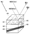
- FIG. 4 is a diagram for explaining the relationship between the WLI light and NBI light emitted from the endoscope according to the first embodiment and blood vessels in the mucous membrane of the subject
- FIG. 5 is a diagram showing the relationship between the DRI light and the subject. It is a figure for demonstrating the relationship with the blood vessel in the mucous membrane of a sample.
- WLI light white light
- blood vessels and the like existing in the mucous membrane can be reproduced on the monitor in colors that are natural for a person (doctor).
- WLI light white light
- the capillaries and mucosal fine patterns on the surface layer of the mucosa cannot always be clearly reproduced for human recognition.
- NBI Near Band Imaging
- the capillaries 64 in the mucosal surface layer 61 absorb the blue light (415 nm) in the NBI light, and as a result, the capillaries 64 are clearly visualized.
- the green light (540 nm) visualizes the blood vessels 65 in the layer 62 slightly deeper than the surface layer. As a result, the capillaries and the mucosal fine patterns on the mucosal surface layer 61 are emphasized and displayed.
- the wavelength of the NBI light which is a narrow band light, may be set to another different wavelength for special light observation.
- DRI Direct Red Imaging
- the subject is irradiated with the DRI light to obtain normal light.
- the blood vessel 66 or blood flow information from the deep mucosa layer to the submucosal layer (layer 63 in FIG. 5), which is difficult to see by observation, may be highlighted.
- fluorescence observation AFI AutoFluorescence Imaging
- the subject is irradiated with a predetermined excitation light for fluorescence observation and the neoplastic lesion and the normal mucosa are highlighted in different colors. It has become.
- the optical system 21 and the image sensor 22 can be controlled by the acquisition condition setting information.
- the exposure time of the image sensor can be changed by setting the acquisition conditions. Is. Exposure control can also eliminate the effects of saturation and low-luminance noise.
- the acquisition condition designation unit 35 sets the acquisition condition setting information for defining the display acquisition condition, which is a condition for acquiring a display image having excellent visibility (hereinafter, display acquisition condition setting information). ) And acquisition condition setting information (hereinafter referred to as analysis acquisition condition setting information) that defines the analysis acquisition condition, which is a condition for acquiring an image for analysis with excellent analyst in image analysis processing, are mixed. It may be generated by letting it occur. For example, only the display acquisition condition setting information may be output in the predetermined first period, and the display acquisition condition setting information and the analysis acquisition condition setting information may be mixed and output in the predetermined second period.
- the video processor 3 can output a display image having excellent visibility based on the display acquisition condition setting information, and the light source device 4 ( It controls at least one of the illumination unit 23), the optical system 21, the image sensor 22, and the image processing unit 12. Further, when the video processor 3 inputs the display acquisition condition setting information and the analysis acquisition condition setting information in a mixed manner, the display image having excellent visibility and the image having excellent analysis property are output. As described above, at least one of the light source device 4 (illumination unit 23), the optical system 21, the image pickup element 22, and the image processing unit 12 is controlled based on the display acquisition condition setting information and the analysis acquisition condition setting information.
- the display acquisition conditions bring the wavelength of the light source closer to natural light (daylight) so that it can be felt naturally when a doctor searches for the affected area with natural light or illuminates the affected area (mainly the surface) for observation.
- This is an imaging and lighting condition for performing image processing that emphasizes visibility on the imaging result and setting the frame rate and the like with an emphasis on continuity.
- the acquisition conditions for analysis are imaging and lighting conditions that increase the amount of effective information for image judgment rather than the visibility of the doctor, and the wavelength of the light source is assumed to reach not only the surface of the affected area but also the inside of the affected area.
- image processing that emphasizes the amount of effective information for analysis is performed, and the frame rate and the like are set with an emphasis on analyticity so that it is easier to determine specific patterns and image features rather than continuity.
- 6 to 8 show an image captured by the video processor 3 and output to the monitor 5 when the display acquisition condition setting information and the analysis acquisition condition setting information are mixed and input to the video processor 3. It is explanatory drawing which shows an example of the image or the image supplied to the image analysis unit 32.
- FIG. 6 shows a series of frames obtained by imaging the image sensor 22.
- WLI ⁇ Raw> indicates a captured image having a high frame rate (for example, 30 FPS or more) obtained by imaging using a high amount of WLI light as illumination light.
- NBI ⁇ Raw> in FIG. 6 shows an image captured at a low frame rate (for example, about 1 FPS) obtained by imaging (narrow band imaging) using NBI light as illumination light.
- the low light amount WLI ⁇ Raw> indicates a low frame rate (for example, 1 FPS) captured image obtained by imaging using a low light amount WLI light as illumination light.
- the WLI ⁇ Raw> frame is used to generate a display image.
- the NBI ⁇ Raw> frame and the low light amount WLI ⁇ Raw> frame are used to generate an image for analysis.
- the WLI ⁇ Raw> frame may be used to generate an image for analysis.
- a DRI ⁇ Raw> frame obtained by imaging using DRI light as illumination light is acquired at a low frame rate (about 1 FPS) as an image to be captured for image analysis.
- a low frame rate about 1 FPS
- an image captured by the excitation light for AFI observation may be acquired. In this way, since the conditions for acquiring the imaged result are changed at the same position where the object is imaged, useful information can be acquired with a simple configuration without complicated operations.
- a display image having excellent visibility can be obtained from an image captured at a high frame rate (for example, 30 FPS or more) obtained by imaging using a high amount of WLI light as illumination light.
- the light source setting conditions, the optical system setting conditions, the imaging setting conditions, and the like for obtaining such an image are the display acquisition conditions.
- an image obtained by observing special light such as an NBI ⁇ Raw> frame
- an image having excellent analyzability of image analysis can be obtained, and a light source for obtaining such an image.
- the setting conditions of the above, the setting conditions of the optical system, the setting conditions of imaging, and the like are the acquisition conditions for analysis.
- the image processing condition for obtaining an image having excellent visibility is a display acquisition condition
- the image processing condition for obtaining an image having excellent analyst property is an analysis acquisition condition.
- FIG. 9 is a chart showing specific examples of display acquisition conditions and analysis acquisition conditions regarding image processing, and is for explaining an example of conditions that can be realized by image processing of the image processing unit 12.
- the video processor 3 performs gamma processing according to the characteristics of the human eye in accordance with display acquisition conditions with respect to gamma processing among image processing performed on an imaging signal. Further, the video processor 3 does not perform gamma processing unnecessary for the analysis processing according to the acquisition conditions for analysis.
- the video processor 3 obtains a display image as shown in FIG. 9 with respect to other image processing such as white balance, color correction, noise reduction, and image enhancement. Distinguish between image processing for obtaining an image for analysis and image processing for obtaining an image for analysis.
- the image processing unit 12 of the video processor 3 acquires a WLI image for display having excellent visibility from the captured image of WLI ⁇ Raw> by performing signal processing according to the display acquisition condition setting information.
- the navigation device 30 outputs the WLI image having excellent visibility to the monitor 5 as a display image.
- FIG. 7 shows this, and the control unit 31 of the navigation device 30 extracts the WLI image from the images output from the video processor 3 and outputs it to the monitor 5.
- the WLI image obtained by the image processing for WLI ⁇ Raw> is extracted and supplied to the monitor 5 from the series of frames of FIG.
- the image is taken so that the frame rate of the WLI image supplied to the monitor 5 is, for example, 30 FPS or more. Since the operation is performed by looking at the image for visual confirmation, the image frame is eliminated as much as possible per hour, but this is not the case, for example, if the image does not change.
- the captured image obtained by the imaging device 20 of the endoscope 2 is displayed on the display screen of the monitor 5.
- the image displayed on the monitor 5 is a WLI image having excellent visibility, and the operator can confirm the image in the visual field range of the imaging device 20 as an easy-to-see image on the display screen of the monitor 5.
- the WLI image with excellent visibility may lack useful information for image analysis for navigation due to signal processing in the image processing unit 12. Therefore, as shown in FIG. 9, the video processor 3 stops a lot of image processing on the image for analysis according to the acquisition condition for analysis, and adds information useful for image analysis. In this way, the analysis acquisition condition setting information makes it possible to output an analysis image useful for image analysis.
- the control unit 31 gives all the output images of the video processor 3 including the NBI image to the image analysis unit 32 to perform image analysis.
- FIG. 8 shows an image supplied to the image analysis unit 32.
- the control unit 31 may provide the image analysis unit 32 with only the images excluding the WLI image among the output images of the video processor 3.
- the image analysis unit 32 performs various image analysis to support the surgeon.
- the image analysis unit 32 performs image analysis on the captured image input from the video processor 3 and obtains an image analysis result.
- the image analysis unit 32 acquires, for example, an image analysis result regarding the traveling direction of the insertion portion of the endoscope 2 or an image analysis result regarding the discrimination result of the lesion portion.
- the image analysis result of the image analysis unit 32 is given to the support information generation unit 36.
- the support information generation unit 36 generates support information based on the image analysis result of the image analysis unit 32. For example, when the support information generation unit 36 obtains a direction in which the insertion unit should be inserted from the image analysis result, the support information generation unit 36 generates support information indicating the insertion direction. Further, for example, when the support information generation unit 36 obtains the discrimination result of the lesion part from the image analysis result, the support information generation unit 36 generates the support information for presenting the discrimination result to the operator.
- the support information generation unit 36 may generate support display data such as an image (support image) or text (support text) to be displayed on the monitor 5 as support information. Further, the support information generation unit 36 may generate audio data for outputting audio from a speaker (not shown) as the support information.
- the navigation device 30 can change the image acquisition conditions based on the characteristics of the image used for the analysis and the image analysis result including various information acquired from the image. There is.
- the determination unit 34 determines whether or not the image acquisition condition should be changed and how the image acquisition condition should be changed. For example, when the determination unit 34 determines that a sufficient analysis result cannot be obtained or a more detailed image analysis is required based on the image analysis result, the determination unit 34 obtains the acquisition conditions necessary for performing the desired image analysis. The change is instructed to the acquisition condition designation unit 35.
- the determination unit 34 may decide to change to a specific acquisition condition based on a specific criterion. For example, the determination unit 34 may determine the acquisition condition to be changed by comparing the values included in the image analysis result such as the contrast information and the histogram information acquired from the image used for the analysis with a predetermined reference value. .. Further, the determination unit 34 may determine whether or not the image used for analysis includes a specific image feature or pattern by pattern matching or the like, and determine the acquisition condition to be set based on the result.
- the determination unit 34 instructs the acquisition condition designation unit 35 to change to the acquisition conditions necessary for obtaining the desired analysis result according to not only the image analysis result but also the observation mode and the content of the procedure. It may be.
- FIG. 10 is a flowchart for explaining the operation of the first embodiment
- FIG. 11 is an explanatory diagram for explaining an image acquired in a specific use case.
- FIG. 11 shows the same usage scene as that of FIG. 3, and shows a state in which an endoscope 2 (rigid scope) is inserted into a body cavity to observe internal tissues and organs.
- an endoscope 2 rigid scope
- the acquisition condition designation unit 35 of the navigation device 30 reads the display acquisition condition setting information in the initial setting from the acquisition condition storage unit 33 and supplies it to the video processor 3.
- the display acquisition condition setting information enables the setting of the acquisition condition for acquiring the display image
- the image pickup parameter setting unit 13 in the control unit 11 of the video processor 3 provides the display acquisition condition setting information.
- the acquisition condition I1 in FIG. 10 is, for example, an acquisition condition corresponding to the display acquisition condition setting information in the initial setting, and is a predetermined condition.
- the light source device 4 emits a high amount of WLI light from the illumination unit 23, and the control unit 11 drives the image pickup device 22 at a high frame rate (for example, 30 FPS or more), whereby the image pickup device 20 To output the captured image of WLI ⁇ Raw>.
- the image processing parameter setting unit 14 in the control unit 11 sets the image processing parameters of the image processing unit 12 based on the display acquisition condition setting information.
- the image processing unit 12 performs gamma processing, white balance processing, and human eye characteristics according to the characteristics of the human eye with respect to the image captured from the image pickup device 20.
- a WLI image suitable for display is generated.
- the WLI image acquired by the image processing unit 12 is supplied to the navigation device 30.
- the control unit 31 outputs the input WLI image as a display image to the monitor 5. In this way, a WLI image having excellent visibility is displayed on the display screen of the monitor 5. The surgeon can surely observe the internal tissues and organs in the body cavity by the WLI image having good visibility on the display screen of the monitor 5.
- the control unit 31 determines in step S2 whether or not the specific timing for changing from the acquisition condition I1 to the acquisition condition I2 has come.
- Support by the navigation device 30 is not always required for the entire period from the start to the end of surgery or examination. Considering the amount of image analysis processed by the navigation device 30, it is considered preferable to provide support by the navigation device 30 only when support is required. Therefore, the control unit 31 sets the transition timing from the acquisition condition I1 based on the display acquisition condition setting information to the acquisition condition I2 including the analysis acquisition condition setting information when instructed by the surgeon or in a predetermined medical scene. It is determined that it has been reached and switched.
- Acquisition condition I2 is a predetermined condition. The acquisition conditions I1 and I2 can be set to appropriate contents by user settings.
- control unit 31 determines that the specific timing has been reached according to the operation of the operator, for example, the process proceeds to step S3, and the acquisition condition designation unit 35 is instructed to shift to the acquisition condition I2.
- the control unit 31 shifts the process to step S4.
- step S3 the acquisition condition designation unit 35 reads the acquisition condition setting information including the display acquisition condition setting information and the analysis acquisition condition setting information and outputs the acquisition condition setting information to the video processor 3 to shift to the acquisition condition I2. That is, the acquisition condition I2 is a condition for acquiring not only the display image but also the analysis image by using the display acquisition condition setting information and the analysis acquisition condition setting information.
- the light source device 4, the optical system 21, and the image sensor 22 are controlled by the image pickup parameter setting unit 13 and the image processing parameter setting unit 14, and acquire WLI ⁇ Raw> at a frame rate of, for example, 30 FPS or more.
- an image suitable for image analysis is acquired.
- the image pickup apparatus 20 repeatedly acquires WLI ⁇ Raw>, WLI ⁇ Raw>, NBI ⁇ Raw>, WLI ⁇ Raw>, low light amount WLI ⁇ Raw>, and WLI ⁇ Raw> frames. ..
- FIG. 11 In the example of FIG.
- the image processing parameter setting unit 14 controls the image processing unit 12 based on the display acquisition condition setting information and the analysis acquisition condition setting information. As a result, the image processing unit 12 acquires the WLI image by performing signal processing on the WLI ⁇ Raw> frame based on the display acquisition condition setting information. Further, the image processing unit 12 does not perform signal processing for display, for example, on the NBI ⁇ Raw> and low light amount WLI ⁇ Raw> frames based on the analysis acquisition condition setting information. The image processing unit 12 converts the NBI ⁇ Raw> frame and the low light amount WLI ⁇ Raw> frame into an NBI image and a low light amount WLI image, respectively. The image processing unit 12 outputs these images to the navigation device 30.
- the control unit 31 of the navigation device 30 outputs the WLI image as a display image to the monitor 5, and outputs the NBI image and the low light amount WLI image to the image analysis unit 32.
- the WLI image is also given to the image analysis unit 32.
- the image analysis unit 32 performs image analysis using the WLI image, the NBI image, and the low light amount WLI image, and obtains a predetermined analysis result. For example, in the case of providing diagnostic support, the image analysis unit 32 can obtain desired analysis results such as the presence / absence of a lesion candidate and the discrimination of a lesion.
- the image analyzed by the image analysis unit 32 includes an image obtained by special light observation such as an NBI image suitable for analysis, and is not subjected to image processing accompanied by lack of information. It has a sufficient amount of information for analysis, and the image analysis unit 32 can obtain a highly accurate analysis result.
- This amount of information is the information that each pixel has to derive something from the image, and changes in the arrangement of pixels are noticeable, such as contrast, spatial frequency, gradation characteristics, color changes, and their changes.
- the amount of information required to identify the characteristics of the object of each image to be analyzed, such as the distinctiveness of wavelength differences, is assumed.
- step S4 and the determination of step S5 are performed after step S2 or S3, but in the case of NO determination in step S5, the process shifts to step S7.
- step S7 it is determined whether or not the support display is necessary. For example, when a lesion candidate is found based on the image analysis result of the image analysis unit 32, the control unit 31 determines that support display is necessary and causes the support information generation unit 36 to generate support information. .. The support information generation unit 36 generates support information based on the analysis result of the image analysis unit 32.
- the support information generation unit 36 puts a mark (support display) indicating the position of the lesion candidate on the display image displayed on the display screen of the monitor 5 as support information when the lesion candidate is found.
- Display data for display may be generated.
- the control unit 31 gives the display data generated by the support information generation unit 36 to the monitor 5. In this way, a mark indicating the position of the lesion candidate is displayed on the display image (observed image by the endoscope 2) displayed on the monitor 5 (step S8).
- the WLI image having excellent visibility is displayed on the monitor 5, so that the affected part or the like can be easily confirmed, and the NBI image or the like suitable for image analysis is used for support. It is possible to obtain highly accurate analysis results and provide extremely effective support for the surgeon.
- the image for analysis is acquired only when support is required, which enables high-quality display without unnecessarily reducing the frame rate of the display image and the processing of image analysis. It is possible to prevent the amount from increasing unnecessarily.
- these display images and analysis images are acquired based on the image pickup signal of the image pickup device 20, and it is not necessary to arrange a plurality of image pickup devices at the tip end portion of the endoscope insertion portion. There is no need for high-performance hardware because the amount of information processing to be processed is significantly increased.
- step S4 the determination unit 34 acquires whether or not the acquisition conditions should be changed in order to acquire the analysis result with higher accuracy based on the analysis image and the image analysis result of the image analysis unit 32. Judge the conditions.
- the determination unit 34 determines whether or not an analysis result with even higher accuracy can be obtained (step S5), and if it is obtained, causes the acquisition condition designation unit 35 to set the acquisition condition I3 for that purpose (step S6). ). If the determination unit 34 determines that it is not possible to obtain an analysis result with even higher accuracy, the determination unit 34 shifts the process to step S7.
- step S6 the acquisition condition designation unit 35 reads out the display acquisition condition setting information and the analysis acquisition condition setting information from the acquisition condition storage unit 33 according to the determination result of the determination unit 34, and sets the acquisition condition I3 as the image pickup parameter setting unit 13. And output to the image processing parameter setting unit 14. That is, the acquisition condition I3, which is adaptively changed according to the output of the video processor 3, is fed back to the video processor 3.
- the acquisition condition designation unit 35 generates and outputs display acquisition condition setting information and analysis acquisition condition setting information according to the determination result of the determination unit 34, not the information stored in the acquisition condition storage unit 33. May be good.
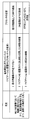
- FIG. 12 is a chart for explaining an example of the acquisition condition I3 based on the determination by the determination unit 34.
- the status column of FIG. 12 shows the information obtained from the analysis result of the image analysis unit 32, and the feedback content shows the acquisition condition I3 specified by the acquisition condition designation unit 35 based on the determination result of the determination unit 34.
- the image analysis unit 32 can perform image analysis using this display image (WLI image).
- the determination unit 34 shifts from step S2 to step S4, the determination unit 34 makes a determination using the analysis result of the WLI image of the image analysis unit 32.
- the image analysis unit 32 shall obtain blood vessel information related to the mucous membrane from the analysis result for the WLI image.
- the determination unit 34 determines that many blood vessels can be seen on the surface layer of the mucous membrane, it acquires an image for analysis such as an NBI image using long wavelength illumination light as acquisition condition I3. Set the conditions.
- the display image (short wavelength image) using the short wavelength illumination light makes it easy to confirm the microvessels on the surface of the tissue. Therefore, when many microvessels are visible, it is determined that some malignant tumor may be lurking based on the blood vessel information in the mucosal surface layer, and the microvascular structure in the mucosal surface layer can be grasped more clearly.
- the acquisition condition I3 for acquiring the NBI image or the like as the analysis image is set.
- the determination unit 34 determines that the microblood vessels of the submucosal surface layer portion are based on the analysis result based on the analysis image.
- a DRI image by DRI special light observation with a short wavelength is acquired so that blood vessel information in the deeper part of the mucosa (for example, blood vessel information in the submucosal layer from the deeper layer of the mucosa) can be obtained.
- the acquisition information I3 for this is set.
- the determination unit 34 increases or decreases the frame rate of the display image according to the magnitude of the movement of the image of the subject affected portion in the image analyzed by the image analysis unit 32, and the type of the image of the analysis image.
- the acquired information I3 for increasing / decreasing is set.
- the determination unit 34 sets the acquired information I3 for changing the brightness of the image for analysis according to the brightness information around the affected part of the subject in the image analyzed by the image analysis unit 32. For example, when the image around the affected area of the subject is dark, the acquired information I3 for brightening the brightness of the image for analysis is set, and when the image around the affected area of the subject is bright, the brightness of the image for analysis is set. The acquired information I3 for darkening the image is set. It should be noted that such control can be performed by appropriately modifying the amount of light of the light source, the exposure time of the image sensor, and the like. In this way, the support display in step S8 is performed using the image acquired based on the acquisition condition I3.
- the determination unit 34 is designed to repeatedly change the setting contents of the acquisition condition I3 as necessary. May be good.
- the display acquisition condition setting information for acquiring the display image in the predetermined first period is output, and for example, in the predetermined second period corresponding to the operation of the operator or the like.
- An example of acquiring a display image and an analysis image by mixing the display acquisition condition setting information and the analysis acquisition condition setting information has been described.
- the surgeon sets the first period in the process of moving the insertion portion of the endoscope 2 to the observation target site, and detects the lesion candidate after the tip of the endoscope 2 reaches the observation target site.
- the second period may be set at the time of starting.
- the acquisition condition I1 is first shown as an example of being generated using only the display acquisition condition setting information for acquiring the display image, but after the power is turned on, the display acquisition condition and the analysis acquisition condition May be set at all times.
- the acquisition condition I1 it is set so that one, for example, NBI ⁇ Raw> frame is acquired for every predetermined number of WLI ⁇ Raw> frames, and the WLI image based on WLI ⁇ Raw> is used as the display image.
- WLI image and NBI image based on NBI ⁇ Raw> may be used as an image for analysis.
- a high-quality image can be displayed by a WLI image having a relatively high frame rate, and analysis necessary for support can be performed with the processing load of the navigation device 30 sufficiently reduced. It is possible. Then, by setting the acquisition condition I2 in which the acquisition rate of the analysis image is increased based on the analysis result or by the operation of the operator, high-precision analysis according to the support requested by the operator is performed. Is possible.
- FIG. 13 is an explanatory diagram for explaining the support display.
- FIG. 13 shows a state in which the endoscope 2 is inserted into the body cavity P to observe internal tissues and organs, and the arrows indicate the illumination light emitted from the tip of the rigid mirror and the reflected light thereof. , The reflected light is incident on the imaging device 20 of the endoscope 2.
- the display image (Im1) obtained under the acquisition condition I1 is obtained by observing white light, and is close to the result seen in natural light that humans are accustomed to. That is, in this example, the acquisition condition I1 is a condition for obtaining a display image with an emphasis on visibility.
- the acquisition condition I1 is a condition for obtaining a display image with an emphasis on visibility.
- the reflected component from the surface of the object is superior and the information inside the tissue is relatively reduced. Therefore, even if there is some abnormality in the part surrounded by the broken line, it cannot be found. It can be difficult.
- Image for analysis under acquisition condition I2 Since the image for analysis under the acquisition condition I2 is an image (Im2) acquired under the imaging condition and the image processing condition including the observation light condition that enables the inside of the tissue to be observed, the change inside the tissue that does not appear on the surface of the body tissue. Can be detected.
- FIG. 13 shows the lesions detected in the image by hatching.
- the analysis image under the acquisition condition I3 is an image (Im3) obtained by using the acquisition condition changed from the acquisition condition I2 in order to obtain a more accurate analysis result.
- the shape of the lesion is clearer than that of the image Im2.
- the analysis result using the image (Im3) is often more accurate than the analysis result using the image (Im2).
- the support information generation unit 36 generates support information based on a more accurate analysis result.
- the support information is display data indicating the shape of the lesion.
- the control unit 31 superimposes and displays the display based on the support information on the display image (Im1).
- the support information generation unit 36 may generate display data as support information for displaying a text display such as "find a lesion" in the vicinity of the position of the broken line portion. In this way, the observer can confirm the display indicating the presence of the lesion portion detected by the image analysis unit 32 on the display image that is natural to the human eye, and the observer can use this portion in another method. It is also possible to take measures such as re-examination at.
- the support display method by the support information generation unit 36 can be improved and customized in various ways. For example, in FIG. 13, an example of displaying the support display based on the analysis image based on the acquisition condition I3 has been described, but the support display based on the analysis image based on the acquisition condition I2 may be displayed. Further, the support information generation unit 36 may display the analysis image as it is or display the composite image based on the analysis result as the support display.
- the determination unit 34 may need to consider a plurality of requests (acquisition conditions) when changing the acquisition conditions according to the situation.
- FIG. 14 is a chart for explaining the priority for such a plurality of requests.
- the peripheral image is dark, and the movement on the image is large.
- the determination unit 34 obtains a bright image such as a DRI image using a long wavelength as the analysis image without lowering the frame rate of the display image.
- the acquisition condition I3 for enabling is generated.
- the determination unit 34 prioritizes each request (condition) and determines the acquisition condition I3. For example, the determination unit 34 has a priority of 1 on the condition that the frame rate of the display image is not lowered. Further, the determination unit 34 is required to acquire a DRI image or the like using a long wavelength as an analysis image as the priority order 2. Further, the determination unit 34 is subject to the condition that a bright image is acquired as the priority order 3.
- the determination unit 34 instructs the acquisition condition designation unit 35 to generate the acquisition condition I3 in consideration of such a priority.
- the acquisition condition designation unit 35 generates display acquisition condition setting information for maintaining the frame rate of the WLI ⁇ Raw> frame used as the display image at 30 FPS or more.
- the acquisition condition designation unit 35 generates analysis acquisition condition setting information for acquiring a DRI image by a DRI ⁇ Raw> frame for generating a DRI image which is an analysis image in 2 FPS.
- the acquisition condition designation unit 35 does not support the request of priority 3 in consideration of the limitation of the maximum frame rate that can be imaged.
- the video processor 3 can efficiently acquire images useful for both display and analysis.
- various types of endoscopes and video processors having different performances and functions can reliably acquire images according to acquisition conditions.
- FIG. 1 shows an example in which the video processor 3 and the navigation device 30 are separately configured, it is clear that the navigation device 30 may be configured to be built in the video processor 3.
- the endoscopic system is not limited to the laparoscopic surgery system, and may be applied to an endoscopic system using a normal flexible endoscope.
- the analysis of the image analysis unit 32, the determination of the determination unit 34, the generation of the acquisition condition setting information of the acquisition condition designation unit 35, and the like in the navigation device 30 may be realized by the AI (artificial intelligence) device.
- FIG. 15 is a flowchart showing an operation flow adopted in the second embodiment.
- the hardware configuration in this embodiment is the same as that in FIG. 1, and the description thereof will be omitted.
- the present embodiment determines which of these analysis results has higher accuracy when the acquisition condition I1 is changed to the acquisition condition I2. It should be noted that the higher accuracy of the analysis result means that a more suitable analysis result can be obtained for support as described above, for example, when the amount of information obtained from the image increases. including.
- the present embodiment when it is determined that a more accurate analysis result can be obtained by changing the conditions, further changes of the same type as the changed contents of the acquisition conditions are made, and if not, the acquisition conditions are obtained. It is possible to set the optimum acquisition conditions by making changes of a type different from the changes made in.
- Further changes of the same type as the changes in the acquisition conditions include, for example, when the acquisition condition I1 for acquiring a normal light observation image is changed to the acquisition condition I2 for acquiring an NBI image, the wavelength of the NBI light. It is a change that changes. Further, the change of the type different from the change content of the acquisition condition is, for example, when the acquisition condition I1 for acquiring the normal light observation image is changed to the acquisition condition I2 for acquiring the NBI image, the change is changed to the NBI image. Instead, it means changing the acquisition conditions for acquiring the DRI image.
- the acquisition condition storage unit 33 has an acquisition condition I3 when a more accurate analysis result is obtained for the combination of the acquisition conditions I1 and I2, and an acquisition condition I3 when the accuracy of the analysis result is lowered. May be registered in advance.
- the determination unit 34 can read any of the stored contents of the acquisition condition storage unit 33 into the acquisition condition designation unit 35 according to the determination result of whether the analysis result has become high accuracy or the accuracy has decreased. It may be instructed whether to do it.
- step S11 of FIG. 15 the image is captured based on the predetermined acquisition condition I1.
- the image is acquired by the endoscope 2 under the control of the control unit 11 of the video processor 3, and the captured image is captured via the navigation device 30. Is supplied to the monitor 5.
- the acquisition condition I1 for example, it is assumed that the display acquisition condition setting information is adopted and the WLI ⁇ Raw> frame is acquired.
- the image processing unit 12 outputs a WLI image based on the WLI ⁇ Raw> frame to the navigation device 30, and the control unit 31 supplies the WLI image to the monitor 5 and displays it on the screen. In this way, a WLI image having excellent visibility is displayed on the display screen of the monitor 5.
- the video processor 3 provisionally records the WLI image acquired based on the acquisition condition I1 as the captured image Im1 on a recording device (not shown) (step S12). Further, the image analysis unit 32 of the navigation device 30 obtains an analysis result by image analysis of the WLI image acquired based on the acquisition condition I1.
- the control unit 31 determines in step S13 whether or not there is an instruction to change the acquisition condition. Similar to the first embodiment, for example, it is possible to generate an instruction to change the acquisition condition according to the instruction of the operator, and the determination unit 34 determines the acquisition condition based on the analysis result of the image analysis unit 32. It is also possible to generate a change instruction.
- the control unit 31 causes the acquisition condition designation unit 35 to generate a predetermined acquisition condition I2.
- the acquisition condition designation unit 35 may read the information of the acquisition condition I2 from the acquisition condition storage unit 33.
- the acquisition condition I2 is a condition for acquiring a WLI image having a predetermined frame rate or higher and, for example, an NBI image.
- the acquisition condition I2 is a condition for acquiring a WLI image having a predetermined frame rate or higher and, for example, an NBI image.
- an acquired image including the WLI ⁇ Raw> frame and the NBI ⁇ Raw> frame is acquired by the endoscope 2 (step S14).
- the image processing unit 12 generates a WLI image and an NBI image based on the image captured by the image pickup device 20, and outputs the WLI image and the NBI image to the navigation device 30.
- the image analysis unit 32 obtains an analysis result by image analysis of the WLI image and the NBI image acquired based on the acquisition condition I2.
- the support information generation unit 36 generates support information based on the analysis result.
- the video processor 3 provisionally records the WLI image and the NBI image acquired based on the acquisition condition I2 as the captured image Im2 on a recording device (not shown) (step S15).
- step S16 the determination unit 34 determines whether or not an image based on the acquisition conditions I1 and I2 has been acquired for the same observation site. For example, the determination unit 34 can determine whether or not the image is based on the same observation site based on the analysis result of the image analysis unit 32.
- the determination unit 34 determines that each image based on the acquisition conditions I1 and I2 is for the same observation site, in the next step S17, the amount of information (hereinafter, the part described as the amount of information is something). It is determined whether or not the amount of information representing the characteristics of the object included in the image to be used for support and assistance has increased. That is, the determination unit 34 irradiates the same region with the amount of information of the image Im1 based on the acquisition condition I1 obtained by irradiating a certain region of the subject with WLI light and NBI light. The amount of information of the image Im2 based on the acquisition condition I2 obtained by the above is compared with the amount of information. The determination unit 34 provides relative information between the amount of information of the image Im1 (the amount of information required to obtain effective support) and the amount of information of the image Im2 (the amount of information required to obtain effective support). It is determined which is the image with a large amount.
- the determination unit 34 determines that a more effective image can be acquired by the same type of acquisition condition.
- the acquisition condition designation unit 35 is instructed to set the same type of acquisition condition I3.
- the part described as the image condition of the same type of change content does not need to be further changed such as image acquisition and processing when an image with a sufficient amount of information is obtained.
- the acquisition condition designation unit 35 changes the information for acquiring an image by NBI light in a wavelength band different from the wavelength band specified in the acquisition condition I2 as the acquisition condition I3 of the same type as the acquisition condition I2, for example.
- the endoscope 2 acquires an acquired image including a WLI ⁇ Raw> frame having a predetermined frame rate or higher and an NBI ⁇ Raw> frame based on NBI light having a wavelength different from the previous one.
- the image processing unit 12 generates a WLI image and an NBI image based on the image captured by the image pickup device 20, and outputs the WLI image and the NBI image to the navigation device 30.
- the image analysis unit 32 obtains an analysis result by image analysis of the WLI image and the NBI image acquired based on the acquisition condition I2.
- the support information generation unit 36 generates support information based on the analysis result.
- the video processor 3 provisionally records the WLI image and the NBI image acquired based on the acquisition condition I3 as the captured image Im3 on a recording device (not shown) (step S19).
- step S17 if it is determined in step S17 that the amount of information has not increased, the determination unit 34 shifts the process to step S20 and determines whether or not the amount of information has decreased. That is, the determination unit 34 irradiates the same region with WLI light and NBI light rather than the amount of information of the image Im1 based on the acquisition condition I1 obtained by irradiating a certain region of the subject with WLI light. It is determined whether or not the amount of information of the image Im2 based on the acquisition condition I2 obtained by the above is reduced.
- the determination unit 34 can acquire an effective image under acquisition conditions different from those of the acquisition condition I2.
- the acquisition condition designation unit 35 is instructed to set different types of acquisition conditions I3.
- the acquisition condition designation unit 35 changes the acquisition condition I2 and the acquisition condition I3 different from the acquisition condition I2 to the information for acquiring the image by the DRI light instead of the NBI light specified in the acquisition condition I2.
- the acquisition condition designation unit 35 includes NBI light in a wavelength band different from the wavelength band of the NBI light specified by the acquisition condition I2 as the acquisition condition I3 different from the acquisition condition I2, and includes DRI light and AFI light.
- the conditions for acquiring the used image may be changed.
- the acquisition condition designation unit 35 may be accompanied by a change in the frame rate of the image sensor 22 or a change in various image processing by the image processing unit 12.
- the image analysis unit 32 obtains an analysis result by image analysis for each image acquired based on the acquisition condition I2 and the heterogeneous acquisition condition I3.
- the support information generation unit 36 generates support information based on the analysis result. Further, the video processor 3 provisionally records each image acquired based on the acquisition condition I2 and the acquisition condition I3 of a different type as the image Im4 on a recording device (not shown) (step S22).
- control unit 31 determines NO in steps S16 and S20 or the process of step S22 is completed, the control unit 31 proceeds to the next step S23, and the images acquired based on the acquisition conditions I1 to I3 are the same observation site.
- the display by the support information from the support information generation unit 36 based on the image analysis results of the images Im2 to Im4 is superimposed and displayed on the image Im1 displayed on the monitor 5.
- FIG. 15 shows an example in which the acquisition condition I3 in steps S18 and S21 is set only once in any of the steps, but step S16 until the amount of information does not increase or decrease.
- ⁇ S22 may be repeatedly executed. However, such repetition can be very time consuming and cannot be determined quickly, so it may be terminated in a particular situation. Of the two conditions, the better one may be used.
- FIG. 16 is a block diagram showing a third embodiment.
- the endoscope system according to the third embodiment includes, for example, a system using an examination endoscope such as a colonoscope, a system using a surgical endoscope such as a laparoscope, and the like. Many endoscopic systems can be applied, but in FIG. 16, the endoscopic system 1 assuming a laparoscopic surgery system is illustrated.
- an endoscope 2 (laparoscope) that images the inside of the body cavity of the subject P and outputs an imaging signal is connected to the endoscope 2 to control the drive of the endoscope 2 and control the drive of the endoscope 2.
- a video processor 3 that acquires an imaging signal related to a subject imaged by the endoscope 2 and performs predetermined image processing on the imaging signal, and a predetermined image processor 3 that is internally installed in the video processor 3 to irradiate the subject.
- a light source device 4 for supplying the illumination light of the above, a monitor 5 for displaying an observation image according to an imaging signal, and a navigation device 30 connected to a video processor 3 are mainly provided, but an inspection endoscope is used.
- the type of endoscope 2 is different in the system, the other components are the same as those shown in FIG.
- each component in the endoscope system 1 of the third embodiment that is, each configuration of the endoscope 2, the video processor 3, the light source device 4, the monitor (display) 5, and the navigation device 30, is the first. Since it is the same as the embodiment of the above, detailed description here will be omitted.
- the navigation device 30 outputs an image in which the lesion site is marked with high accuracy to the monitor (display) 5. It has become like.
- each image information (display) without omission provided by the video processor 3 as described above is provided.
- image information for analysis + image information for analysis for example, an image in which a region considered to be a lesion site is marked with high accuracy is output to the monitor (display) 5 and provided to the operator as navigation information.
- the navigation device 30 outputs an image presenting useful information for the procedure to the monitor (display) 5.
- image information + image information for analysis for example, information such as the position of the tumor, the excision area, and the position of the main blood vessel is output to the monitor (display) 5 and provided to the operator as navigation information.
- the present invention provides image information provided from the video processor 3 to the navigation device 30 as described above in the endoscope system 1 using various endoscopes.
- the image information for analysis for the navigation device 30 is prepared, and the navigation device 30 performs the recognition process using the image information without any omissions.
- Useful navigation information can be provided to the surgeon.
- the endoscope system for examination and the endoscope system for surgery are given as examples, but the third embodiment is not limited to this.
- the endoscopic system according to the embodiment may be applied to an endoscopic system using another type of endoscope.
- the controls and functions mainly described in the flowchart can be set by a program, and the above-mentioned controls and functions can be realized by reading and executing the program by a computer.
- the program may record or store all or part of it on a portable medium such as a flexible disk, a CD-ROM, or a non-volatile memory, or a storage medium such as a hard disk or a volatile memory. It can be distributed or provided at the time of product shipment or via a portable medium or communication line.
- the user can easily realize the image processing device of the present embodiment by downloading the program via a communication network and installing it on a computer, or installing it on a computer from a recording medium. can.
- the present invention is not limited to each of the above embodiments as it is, and at the implementation stage, the components can be modified and embodied within a range that does not deviate from the gist thereof.
- various inventions can be formed by an appropriate combination of the plurality of components disclosed in each of the above embodiments. For example, some components of all the components shown in the embodiment may be deleted. In addition, components across different embodiments may be combined as appropriate.
- a navigation device is a device that detects an abnormality in the fields of industry and security as well as the medical field, and support information can be rewritten as information that encourages awareness.
Abstract
This image processing device is equipped with: an acquisition conditions specification unit for setting, for an image acquisition unit, first acquisition conditions which include display acquisition conditions for acquiring a display image and second acquisition conditions which include the display acquisition conditions and analysis acquisition conditions for acquiring an image for image analysis, which acquires a first image based on the display acquisition conditions, and a second image based on the analysis acquisition conditions; an image analysis unit for subjecting an image acquired by the image acquisition unit to analysis; a support information generation unit for generating support information on the basis of the image analysis results from the image analysis unit; and a control unit for controlling the switching between the first acquisition conditions and the second acquisition conditions.
Description
本発明は、画像を観察する際におけるナビゲーションを行うための画像処理装置、画像処理方法、ナビゲーション方法及び内視鏡システムに関する。
The present invention relates to an image processing device, an image processing method, a navigation method, and an endoscope system for performing navigation when observing an image.
従来、画像処理技術を用いて、各種作業の支援を行うナビゲーション技術が開発されている。例えば、医療分野においては、画像処理技術を用いて、内視鏡の挿入を支援する挿入支援や病状の推定結果の診断支援等が可能となっている。例えば、定量的な判断尺度の提供・診断の際に着目すべき微細構造の特定・画像解析による病状の推定結果などの支援情報を提供するコンピュータ診断支援(Computer Aided Diagnosis:CAD)も開発されている。このようなCADや挿入支援等を実現する画像処理装置においては、術者に適切な支援を与えるための工夫がなされている。
Conventionally, navigation technology that supports various tasks using image processing technology has been developed. For example, in the medical field, it is possible to use image processing technology to support insertion to support the insertion of an endoscope and to support diagnosis of the estimation result of a medical condition. For example, computer-aided diagnosis (CAD), which provides support information such as provision of a quantitative judgment scale, identification of microstructures to be noted in diagnosis, and estimation results of medical conditions by image analysis, has also been developed. There is. In the image processing device that realizes such CAD and insertion support, a device is made to give appropriate support to the operator.
例えば、日本国特開2019-42156号公報には、第1及び第2の医療画像についての2つの解析結果を、位置または範囲(大きさ)等を比較し得るように表示可能にして、解析結果の確認を容易にする技術が開示されている。
For example, in Japanese Patent Application Laid-Open No. 2019-42156, two analysis results for the first and second medical images can be displayed so that the positions or ranges (sizes) can be compared for analysis. Techniques that facilitate confirmation of results are disclosed.
ところで、内視鏡等によって取得されるリアルタイムの医療画像は、画像解析のために画像処理されるだけでなくモニタ等に画像表示させることで、手術や検査等において、患部等の極めて有用な画像情報を術者に提供することができる。しかしながら、日本国特開2019-42156号公報では、取得する画像が手術や検査等時の目視に最適化されておらず、術者にとって必ずしも最適な支援が行われていない。
By the way, real-time medical images acquired by an endoscope or the like are not only image-processed for image analysis but also displayed on a monitor or the like, which is an extremely useful image of the affected area or the like in surgery or examination. Information can be provided to the surgeon. However, in Japanese Patent Application Laid-Open No. 2019-42156, the acquired image is not optimized for visual inspection at the time of surgery, examination, etc., and the optimum support is not always provided to the operator.
本発明は、画像の取得条件を最適化することにより、術者に対して極めて効果的な支援を行うことができる画像処理装置、画像処理方法、ナビゲーション方法及び内視鏡システムを提供することを目的とする。
The present invention provides an image processing device, an image processing method, a navigation method, and an endoscopic system capable of providing extremely effective support to an operator by optimizing the image acquisition conditions. The purpose.
本発明の一態様の画像処理装置は、表示用画像を取得するための表示用取得条件に基づく第1画像と、画像解析用の画像を取得するための解析用取得条件に基づく第2画像とを取得する画像取得部に対して、上記表示用取得条件を含む第1取得条件と上記表示用取得条件及び解析用取得条件を含む第2取得条件とを設定する取得条件指定部と、上記画像取得部により取得された画像に対する画像解析を行う画像解析部と、上記画像解析部の画像解析結果に基づいて支援情報を生成する支援情報生成部と、上記第1取得条件と第2取得条件との切換を制御する制御部と、を具備する。
The image processing apparatus according to one aspect of the present invention includes a first image based on a display acquisition condition for acquiring a display image and a second image based on an analysis acquisition condition for acquiring an image for image analysis. The acquisition condition specification unit that sets the first acquisition condition including the display acquisition condition and the second acquisition condition including the display acquisition condition and the analysis acquisition condition for the image acquisition unit to acquire the image, and the image. An image analysis unit that performs image analysis on the image acquired by the acquisition unit, a support information generation unit that generates support information based on the image analysis result of the image analysis unit, and the first acquisition condition and the second acquisition condition. It is provided with a control unit for controlling the switching of.
本発明の一態様の画像処理方法は、第1、第2の異なる撮像条件で撮像して撮像結果を取得する撮像ステップと、上記異なる撮像条件での複数の撮像結果を比較する比較ステップと、上記比較結果で得られた情報量の差異から、第3の撮像条件を変更する撮像条件変更ステップと、からなる。
The image processing method of one aspect of the present invention includes an imaging step of acquiring imaging results by imaging under different first and second imaging conditions, a comparison step of comparing a plurality of imaging results under the above different imaging conditions, and a comparison step. From the difference in the amount of information obtained in the above comparison result, it is composed of a third imaging condition changing step for changing the imaging condition.
また、本発明の一態様のナビゲーション方法は、表示用画像を取得するための表示用取得条件に基づく第1画像と、画像解析用の画像を取得するための解析用取得条件に基づく第2画像とを取得する画像取得部に対して、上記表示用取得条件を含む第1取得条件を設定し、上記画像取得部に対して上記表示用取得条件及び解析用取得条件を含む第2取得条件を設定し、上記画像取得部により取得された画像に対する画像解析を行い、上記画像解析の結果に基づいて、上記表示用取得条件と、上記第2取得条件に含まれる解析用取得条件とは異なる解析用取得条件と、を含む第3取得条件を上記画像取得部に対して設定する。
Further, the navigation method of one aspect of the present invention includes a first image based on a display acquisition condition for acquiring a display image and a second image based on an analysis acquisition condition for acquiring an image for image analysis. The first acquisition condition including the display acquisition condition is set for the image acquisition unit that acquires and, and the second acquisition condition including the display acquisition condition and the analysis acquisition condition is set for the image acquisition unit. The image is set, image analysis is performed on the image acquired by the image acquisition unit, and based on the result of the image analysis, the display acquisition condition and the analysis acquisition condition included in the second acquisition condition are different from each other. The third acquisition condition including the acquisition condition for use is set for the image acquisition unit.
また、本発明の一態様の内視鏡システムは、表示用画像を取得するための表示用取得条件に基づく第1画像と、画像解析用の画像を取得するための解析用取得条件に基づく第2画像とを取得する照明部と撮像部を有する内視鏡と、上記表示用取得条件と上記解析用取得条件との少なくとも一方に基づいて、上記内視鏡に上記第1画像及び第2画像を取得させるビデオプロセッサと、上記表示用取得条件を含む第1取得条件と上記表示用取得条件及び解析用取得条件を含む第2取得条件とを設定する取得条件指定部と、上記画像取得部により取得された画像に対する画像解析を行う画像解析部と、上記画像解析部の画像解析結果に基づいて支援情報を生成する支援情報生成部と、上記第1取得条件と第2取得条件との切換を制御する制御部と、を備えた画像処理装置と、を具備する。
Further, the endoscope system according to one aspect of the present invention has a first image based on a display acquisition condition for acquiring a display image and a first image based on an analysis acquisition condition for acquiring an image for image analysis. Based on at least one of the display acquisition condition and the analysis acquisition condition, the first image and the second image are displayed on the endoscope based on an endoscope having an illumination unit and an imaging unit for acquiring two images. The image processor, the acquisition condition specification unit that sets the first acquisition condition including the display acquisition condition, the second acquisition condition including the display acquisition condition, and the analysis acquisition condition, and the image acquisition unit. Switching between the image analysis unit that performs image analysis on the acquired image, the support information generation unit that generates support information based on the image analysis result of the image analysis unit, and the first acquisition condition and the second acquisition condition. It includes a control unit for controlling and an image processing device including.
以下、図面を参照して本発明の実施の形態について詳細に説明する。
Hereinafter, embodiments of the present invention will be described in detail with reference to the drawings.
(第1の実施形態)
図1は本発明の第1の実施形態に係る画像処理装置を含む内視鏡システムの構成を示すブロック図である。 (First Embodiment)
FIG. 1 is a block diagram showing a configuration of an endoscope system including an image processing apparatus according to a first embodiment of the present invention.
図1は本発明の第1の実施形態に係る画像処理装置を含む内視鏡システムの構成を示すブロック図である。 (First Embodiment)
FIG. 1 is a block diagram showing a configuration of an endoscope system including an image processing apparatus according to a first embodiment of the present invention.
例えば内視鏡においては、ナビゲーションのための画像解析に用いる画像とモニタに表示する表示用の画像とを別々の撮像装置によって取得しようとすると、内視鏡先端部の大型化が避けられない。このような理由から、一般的には、ナビゲーションのための画像解析に用いる画像としては、表示用の画像が流用される。しかしながら、表示用の画像は、表示に適した取得条件で取得されており、画像解析に必要な情報が欠落している可能性がある。なお、画像解析用の画像は、視認性に劣る可能性があり、画像解析用の画像を表示用の画像として用いることは好ましくない。以上から、見やすい内視鏡画像を表示しながら高精度の解析結果に基づく支援を行うことは困難であった。なお、本明細書において、高精度の解析結果とは、術者に対してより有効な支援を可能にする解析結果のことであり、正確な解析結果を意味するだけでなく、各種解析結果のうち支援に必要な種類の解析結果が得られることを意味するものとする。
For example, in an endoscope, if an image used for image analysis for navigation and an image for display displayed on a monitor are to be acquired by separate imaging devices, it is inevitable that the tip of the endoscope will be enlarged. For this reason, in general, an image for display is diverted as an image used for image analysis for navigation. However, the image for display is acquired under the acquisition conditions suitable for display, and there is a possibility that the information necessary for image analysis is missing. The image for image analysis may be inferior in visibility, and it is not preferable to use the image for image analysis as the image for display. From the above, it has been difficult to provide support based on high-precision analysis results while displaying an easy-to-read endoscopic image. In the present specification, the high-precision analysis result is an analysis result that enables more effective support to the operator, and not only means an accurate analysis result but also various analysis results. Of these, it means that the type of analysis results required for support can be obtained.
そこで、本実施形態においては、取得条件が異なる複数種類の画像であって、視認性に優れた画像表示のための画像と解析性に優れた画像とを含む複数種類の画像を取得可能にすることにより、術者に対して極めて効果的な支援を可能にするものである。なお、解析性に優れた画像とは、高精度の解析結果を得ることを可能にする画像のことである。
Therefore, in the present embodiment, it is possible to acquire a plurality of types of images having different acquisition conditions, including an image for displaying an image having excellent visibility and an image having excellent analystability. This enables extremely effective support for the surgeon. An image having excellent analystability is an image that enables high-precision analysis results to be obtained.
更に、本実施形態においては、視認性に優れた画像表示を維持しながら、解析性に一層優れた画像を取得するために、画像の取得条件を適応的に変化させることも可能である。なお、図1では内視鏡システムを例に説明するが、これに限定されるものではなく、観察を伴う各種作業を実施するための各種装置に適用可能である。
Further, in the present embodiment, it is possible to adaptively change the image acquisition conditions in order to acquire an image having further excellent analyst while maintaining the image display having excellent visibility. Although the endoscope system will be described as an example in FIG. 1, the present invention is not limited to this, and can be applied to various devices for carrying out various operations involving observation.
図2は表示用画像と解析用画像とのニーズを説明するための図表である。
FIG. 2 is a chart for explaining the needs of the display image and the analysis image.
表示用の画像(表示用画像)は、人が画面上に表示された画像を視認することで必要な情報を取得するための画像である。一方、解析用の画像(解析用画像)は、ナビゲーション装置において解析対象となる画像である。人とコンピュータとの情報処理の質を考慮すると、表示用画像と解析用画像とにそれぞれ相応しい特性は相互に異なる。
The display image (display image) is an image for a person to obtain necessary information by visually recognizing the image displayed on the screen. On the other hand, the image for analysis (image for analysis) is an image to be analyzed in the navigation device. Considering the quality of information processing between humans and computers, the characteristics suitable for the display image and the analysis image are different from each other.
図2に示すように、表示用画像は、人が認識し易いように、なるべく有用な情報のみを含む視認性に優れた画像であることが好ましい。例えば、表示用画像の画質は、ノイズが少なく、人の目の特性に近いガンマ処理が施され、見たい周波数帯域が強調された画像であることが好ましい。
As shown in FIG. 2, the display image is preferably an image having excellent visibility that includes only useful information as much as possible so that it can be easily recognized by a person. For example, the image quality of the display image is preferably an image that has less noise, is gamma-processed close to the characteristics of the human eye, and emphasizes the frequency band to be viewed.
一方、解析用画像は、コンピュータ等により処理されることから、解析のための画像情報に含まれる情報量は多いほど有用な解析結果(高精度の解析結果)が得られる。例えば、解析用画像は、画質について、注目部位以外が目立つような画像情報であっても、解析結果に与える悪影響は小さい。また、画像にノイズリダクション、ガンマ処理、画像強調処理等が施されると、解析に必要な情報が欠落することがあるので、解析用画像については、これらの画像処理は施さない方がよい。
On the other hand, since the analysis image is processed by a computer or the like, the larger the amount of information contained in the image information for analysis, the more useful analysis result (high-precision analysis result) can be obtained. For example, the image quality of the analysis image has a small adverse effect on the analysis result even if the image information is such that the part other than the attention portion is conspicuous. Further, if noise reduction, gamma processing, image enhancement processing, or the like is applied to an image, information necessary for analysis may be lost. Therefore, it is better not to perform these image processing on the image for analysis.
また、例えば、粘膜における血管の観察等に有効なNBI(狭帯域光観察(Narrow Band Imaging))等の特殊光観察の場面においては、人の画像認識能力を考えると、モニタ画面に表示される画像としては、1種類だけの特殊光観察画像が表示されるか、または、せめて通常光観察画像に特集光観察画像を重畳する表示に留める方がよい。
Further, for example, in a scene of special light observation such as NBI (Narrow Band Imaging) which is effective for observing blood vessels in a mucous membrane, it is displayed on a monitor screen in consideration of human image recognition ability. As the image, it is better to display only one type of special light observation image, or at least to display the special light observation image superimposed on the normal light observation image.
一方、ナビゲーション装置に複数種類の特殊光観察画像信号が連続的に入力されたとしても画像解析処理に与える悪影響は無く、むしろ複数種類の画像情報により有用な解析結果が得られる可能性が高くなる。
On the other hand, even if a plurality of types of special light observation image signals are continuously input to the navigation device, there is no adverse effect on the image analysis processing, and it is more likely that useful analysis results can be obtained from the plurality of types of image information. ..
また、表示用画像のフレームレートは、人が視認する上で30FPS以上であることが好ましいが、解析用画像については、相対的に低いフレームレート、例えば、1FPS以下のフレームレートであったとしても、有用な情報を得ることが可能である。
Further, the frame rate of the display image is preferably 30 FPS or more for human recognition, but the analysis image has a relatively low frame rate, for example, even if the frame rate is 1 FPS or less. , It is possible to obtain useful information.
(構成)
図3は図1の内視鏡システムの利用形態の一例を示す説明図である。図3を参照して、内視鏡システムの利用形態の一例について説明する。 (composition)
FIG. 3 is an explanatory diagram showing an example of a usage pattern of the endoscope system of FIG. An example of a usage pattern of the endoscope system will be described with reference to FIG.
図3は図1の内視鏡システムの利用形態の一例を示す説明図である。図3を参照して、内視鏡システムの利用形態の一例について説明する。 (composition)
FIG. 3 is an explanatory diagram showing an example of a usage pattern of the endoscope system of FIG. An example of a usage pattern of the endoscope system will be described with reference to FIG.
図3は内視鏡システム1を用いて、被検体Pの腹腔内に対する処置を行う例を示している。内視鏡システム1が腹腔鏡手術システムの例である。内視鏡システム1は、被検体Pの体腔内を撮像し撮像信号を出力する内視鏡2(腹腔鏡)と、内視鏡2を接続し当該内視鏡2の駆動を制御すると共に、当該内視鏡2において撮像した被検体に係る撮像信号を取得し当該撮像信号に対して所定の画像処理を施すビデオプロセッサ3と、ビデオプロセッサ3に内設され、被検体に照射するための所定の照明光を供給する光源装置4と、撮像信号に応じた観察画像を表示するモニタ5と、ビデオプロセッサ3に接続され、診断支援等を行うための画像処理装置であるナビゲーション装置30と、を主に備える。
FIG. 3 shows an example in which the endoscopic system 1 is used to treat the abdominal cavity of the subject P. The endoscopic system 1 is an example of a laparoscopic surgery system. The endoscope system 1 connects an endoscope 2 (laparoscope) that images the inside of the body cavity of the subject P and outputs an image pickup signal to the endoscope 2 and controls the drive of the endoscope 2. A video processor 3 that acquires an image pickup signal related to a subject imaged by the endoscope 2 and performs predetermined image processing on the image pickup signal, and a predetermined image processor 3 that is internally installed in the video processor 3 to irradiate the subject. A light source device 4 that supplies the illumination light of the above, a monitor 5 that displays an observation image according to an imaging signal, and a navigation device 30 that is connected to a video processor 3 and is an image processing device for performing diagnostic support and the like. Mainly prepare.
図3では、被検体Pの腹部に内視鏡2及び処置具7がトラカールを介して挿入されている様子を示している。内視鏡2は、ユニバーサルコードを介してビデオプロセッサ3に接続される。ビデオプロセッサ3には、光源装置4が内蔵されており、光源装置4によって腹腔内が照明されるように構成されている。内視鏡2は、ビデオプロセッサ3により駆動されて、被検体Pの腹腔内を撮像する。内視鏡2によって取得された撮像画像はビデオプロセッサ3によって信号処理された後、ナビゲーション装置30に供給される。
FIG. 3 shows a state in which the endoscope 2 and the treatment tool 7 are inserted into the abdomen of the subject P via a tracal. The endoscope 2 is connected to the video processor 3 via a universal cord. The video processor 3 has a built-in light source device 4, and is configured to illuminate the abdominal cavity by the light source device 4. The endoscope 2 is driven by the video processor 3 to image the abdominal cavity of the subject P. The captured image acquired by the endoscope 2 is signal-processed by the video processor 3 and then supplied to the navigation device 30.
ナビゲーション装置30は、入力された撮像画像をモニタ5に与えて表示すると共に、撮像画像に対する解析処理によって支援情報を生成する。ナビゲーション装置30は、生成した支援情報を、必要に応じてモニタ5に出力して表示させることで、術者に対する支援を行う。
The navigation device 30 gives the input captured image to the monitor 5 and displays it, and also generates support information by analyzing the captured image. The navigation device 30 provides support to the operator by outputting the generated support information to the monitor 5 as needed and displaying it.
本実施形態においては、ナビゲーション装置30は、ビデオプロセッサ3に指示を与えて、内視鏡2の撮像における撮像条件及びビデオプロセッサ3の画像処理における画像処理条件の少なくとも一方を含む画像の取得条件を設定することにより、視認性に優れた画像表示のための画像を取得すると同時に、支援のための画像解析に有効な画像を取得するようになっている。
In the present embodiment, the navigation device 30 gives an instruction to the video processor 3 to set an image acquisition condition including at least one of an imaging condition in the imaging of the endoscope 2 and an image processing condition in the image processing of the video processor 3. By setting, an image for displaying an image having excellent visibility is acquired, and at the same time, an image effective for image analysis for support is acquired.
(内視鏡)
図1において、内視鏡2としては、消化器内視鏡や腹腔鏡等の各種内視鏡を採用することができる。内視鏡2は、被検体の体腔内等に挿入される細長の挿入部、挿入部の基端側に配設され術者が把持して操作を行う操作部を有する。操作部の基端部からはユニバーサルコードが延設されており、このユニバーサルコードにより、内視鏡2は、光源装置4を含むビデオプロセッサ3に着脱自在に接続されるようになっている。 (Endoscope)
In FIG. 1, as theendoscope 2, various endoscopes such as a gastrointestinal endoscope and a laparoscope can be adopted. The endoscope 2 has an elongated insertion portion that is inserted into the body cavity of a subject, and an operation portion that is arranged on the proximal end side of the insertion portion and is gripped and operated by an operator. A universal cord extends from the base end of the operation unit, and the endoscope 2 is detachably connected to the video processor 3 including the light source device 4 by the universal cord.
図1において、内視鏡2としては、消化器内視鏡や腹腔鏡等の各種内視鏡を採用することができる。内視鏡2は、被検体の体腔内等に挿入される細長の挿入部、挿入部の基端側に配設され術者が把持して操作を行う操作部を有する。操作部の基端部からはユニバーサルコードが延設されており、このユニバーサルコードにより、内視鏡2は、光源装置4を含むビデオプロセッサ3に着脱自在に接続されるようになっている。 (Endoscope)
In FIG. 1, as the
挿入部の例えば先端には、撮像装置20が配設される。撮像装置20は、光学系21、撮像素子22及び照明部23を備える。照明部23は、光源装置4により制御されて照明光を発生し、発生した照明光を被写体に照射する。照明部23は、例えばLED(発光ダイオード)等の図示しない所定の光源を有する構成であってもよい。本実施形態においては、照明部23は、通常観察用の白色光を発生する光源及び狭帯域観察用の狭帯域光を発生する光源、所定波長の赤外光を発生する光源等の複数の光源を有していてもよい。照明部23は、様々な照射モードを有しており、光源装置4に制御されて、照明光の波長の切り替えや照射強度、照射の時間的なパターン制御などが可能である。
An imaging device 20 is arranged at, for example, the tip of the insertion portion. The image pickup device 20 includes an optical system 21, an image pickup device 22, and an illumination unit 23. The illumination unit 23 is controlled by the light source device 4 to generate illumination light, and irradiates the subject with the generated illumination light. The illumination unit 23 may have a configuration having a predetermined light source (not shown) such as an LED (light emitting diode). In the present embodiment, the illumination unit 23 is a plurality of light sources such as a light source that generates white light for normal observation, a light source that generates narrow band light for narrow band observation, and a light source that generates infrared light of a predetermined wavelength. May have. The illumination unit 23 has various irradiation modes, and is controlled by the light source device 4, and can switch the wavelength of the illumination light, control the irradiation intensity, and control the temporal pattern of irradiation.
なお、図1では撮像装置20内に照明部23を設ける例について示したが、光源装置4が照明光を発生し、この照明光を図示しないライトガイドにより内視鏡2の先端に導いて、被写体に照射する構成であってもよい。
Although FIG. 1 shows an example in which the illumination unit 23 is provided in the image pickup apparatus 20, the light source apparatus 4 generates illumination light and guides the illumination light to the tip of the endoscope 2 by a light guide (not shown). It may be configured to illuminate the subject.
光学系21は、ズームやフォーカシングのための図示しないレンズや絞り等を備えて、これらのレンズを駆動する図示しないズーム(変倍)機構、ピント及び絞り機構を備えていてもよい。照明部23からの照明光は被検体に照射され、被検体からの戻り光が光学系21を通過して撮像素子22の撮像面に導かれる。
The optical system 21 may include a lens (not shown), an aperture, and the like for zooming and focusing, and may include a zoom (magnification) mechanism, a focus, and an aperture mechanism (not shown) for driving these lenses. The illumination light from the illumination unit 23 irradiates the subject, and the return light from the subject passes through the optical system 21 and is guided to the image pickup surface of the image pickup device 22.
撮像素子22は、CCDやCMOSセンサ等によって構成されており、光学系21からの被写体光学像を光電変換して被写体の撮像画像(撮像信号)を取得する。撮像装置20は、取得した撮像画像をビデオプロセッサ3に出力する。
The image sensor 22 is composed of a CCD, a CMOS sensor, or the like, and obtains an image (imaging signal) of the subject by photoelectrically converting the optical image of the subject from the optical system 21. The image pickup device 20 outputs the acquired captured image to the video processor 3.
ビデオプロセッサ3は、ビデオプロセッサ3の各部、撮像装置20及び光源装置4を制御する制御部11を備えている。制御部11及び制御部11内の各部は、CPU(Central Processing Unit)やFPGA(Field Programmable Gate Array)等を用いたプロセッサによって構成されていてもよく、図示しないメモリに記憶されたプログラムに従って動作して各部を制御するものであってもよいし、ハードウェアの電子回路で機能の一部又は全部を実現するものであってもよい。
The video processor 3 includes each part of the video processor 3, an image pickup device 20, and a control unit 11 that controls the light source device 4. The control unit 11 and each unit in the control unit 11 may be configured by a processor using a CPU (Central Processing Unit), an FPGA (Field Programmable Gate Array), or the like, and operate according to a program stored in a memory (not shown). It may control each part, or it may realize a part or all of the functions by a hardware electronic circuit.
(光源装置)
光源装置4は、照明部23を制御して、白色光及び各種特殊観察用光を発生させる。例えば、光源装置4は、照明部23に、白色光、NBI(狭帯域光観察(Narrow Band Imaging)光、DRI(長波長狭帯域光観察(Dual Red Imaging)光、AFI(蛍光観察(Auto Fluorescence Imaging)のための励起光(以下、AFI光)を発生させてもよい。白色光は、いわゆるWLI(white light imaging)観察(通常観察)用の照明光(以下、WLI光)として利用され、NBI光は、狭帯域光観察に用いられ、DRI光は、長波長狭帯域光観察に用いられ、AIF光は蛍光観察に用いられる。 (Light source device)
Thelight source device 4 controls the illumination unit 23 to generate white light and various special observation lights. For example, the light source device 4 is provided with white light, NBI (Narrow Band Imaging) light, DRI (Dual Red Imaging) light, and AFI (Fluorescence Observation (Auto Fluorescence) light) in the illumination unit 23. Excitation light for (Imaging) (hereinafter, AFI light) may be generated. White light is used as illumination light (hereinafter, WLI light) for so-called WLI (white fluorescence) observation (normal observation). NBI light is used for narrow-band light observation, DRI light is used for long-wavelength narrow-band light observation, and AIF light is used for fluorescence observation.
光源装置4は、照明部23を制御して、白色光及び各種特殊観察用光を発生させる。例えば、光源装置4は、照明部23に、白色光、NBI(狭帯域光観察(Narrow Band Imaging)光、DRI(長波長狭帯域光観察(Dual Red Imaging)光、AFI(蛍光観察(Auto Fluorescence Imaging)のための励起光(以下、AFI光)を発生させてもよい。白色光は、いわゆるWLI(white light imaging)観察(通常観察)用の照明光(以下、WLI光)として利用され、NBI光は、狭帯域光観察に用いられ、DRI光は、長波長狭帯域光観察に用いられ、AIF光は蛍光観察に用いられる。 (Light source device)
The
なお、照明部23は、複数種類のLEDやレーザーダイオードやキセノンランプ等によって構成されてこれらの照明光を発生してもよく、白色光と、NBIフィルタ、DRIフィルタ、AFIフィルタなどを利用して、これらの照明光を生成するようになっていてもよい。照明部23が光量を増減させることで、撮像装置20の撮像時の露出値を変更することができ、飽和や低輝度ノイズの影響を排除した露出制御を可能としている。なお、NBI光として、波長λ=415nmの青色光と、波長λ=540nmの緑色光を発生してもよい。
The illumination unit 23 may be composed of a plurality of types of LEDs, laser diodes, xenon lamps, and the like to generate these illumination lights, and uses white light, an NBI filter, a DRI filter, an AFI filter, and the like. , These illumination lights may be generated. By increasing or decreasing the amount of light, the illumination unit 23 can change the exposure value of the imaging device 20 at the time of imaging, and enables exposure control that eliminates the effects of saturation and low-luminance noise. As NBI light, blue light having a wavelength of λ = 415 nm and green light having a wavelength of λ = 540 nm may be generated.
(ビデオプロセッサ)
ビデオプロセッサ3の制御部11は、画像処理部12、撮像パラメータ設定部13、画像処理パラメータ設定部14及び表示制御部15を備えている。撮像パラメータ設定部13は、光源装置4を制御して、照明部23が発生する照明光の状態を設定することできる。また、撮像パラメータ設定部13は、撮像装置20を制御して、光学系21による光学系の状態及び撮像素子22の駆動状態を設定することができる。 (Video processor)
Thecontrol unit 11 of the video processor 3 includes an image processing unit 12, an imaging parameter setting unit 13, an image processing parameter setting unit 14, and a display control unit 15. The image pickup parameter setting unit 13 can control the light source device 4 to set the state of the illumination light generated by the illumination unit 23. Further, the image pickup parameter setting unit 13 can control the image pickup device 20 to set the state of the optical system by the optical system 21 and the drive state of the image pickup element 22.
ビデオプロセッサ3の制御部11は、画像処理部12、撮像パラメータ設定部13、画像処理パラメータ設定部14及び表示制御部15を備えている。撮像パラメータ設定部13は、光源装置4を制御して、照明部23が発生する照明光の状態を設定することできる。また、撮像パラメータ設定部13は、撮像装置20を制御して、光学系21による光学系の状態及び撮像素子22の駆動状態を設定することができる。 (Video processor)
The
即ち、撮像パラメータ設定部13は、撮像装置20の撮像時における光学的な条件及び撮像素子23の駆動条件を含む撮像条件の設定が可能である。例えば、撮像パラメータ設定部13の設定により、照明光として、NBI光、DRI光、AFI光等を発生させると共に、発生させる照明光の波長や強度等を制御することができる。また、撮像パラメータ設定部13の設定により、撮像装置20は、様々なモードでの撮像信号出力が可能であり、例えば、フレームレート、画素数、画素加算、読み出し領域の変更、感度切換、色信号の弁別出力等を制御することができる。
That is, the image pickup parameter setting unit 13 can set the image pickup conditions including the optical conditions at the time of image pickup of the image pickup apparatus 20 and the drive conditions of the image pickup element 23. For example, by setting the imaging parameter setting unit 13, NBI light, DRI light, AFI light and the like can be generated as illumination light, and the wavelength and intensity of the generated illumination light can be controlled. Further, by setting the image pickup parameter setting unit 13, the image pickup device 20 can output an image pickup signal in various modes, for example, frame rate, number of pixels, pixel addition, change of read area, sensitivity switching, and color signal. It is possible to control the discrimination output of.
なお、撮像素子22から出力される撮像信号はRAWデータと呼ばれることがあり、これは画像処理前のオリジナルなデータとして使われる場合がある。
The image pickup signal output from the image sensor 22 may be called RAW data, which may be used as original data before image processing.
(画像処理部)
画像処理部12は、撮像装置20から取り込まれた撮像画像(動画像及び静止画像)が与えられ、取り込まれた撮像画像に対して、所定の信号処理、例えば、色調整処理、マトリックス変換処理、ノイズ除去処理、画像の合成、適応型処理、その他各種の信号処理を行う。画像処理パラメータ設定部14は、画像処理部12における画像処理の処理パラメータを設定するようになっている。 (Image processing unit)
Theimage processing unit 12 is given an captured image (moving image and still image) captured from the imaging device 20, and receives a predetermined signal processing, for example, color adjustment processing, matrix conversion processing, for the captured image. Performs noise removal processing, image composition, adaptive processing, and various other signal processing. The image processing parameter setting unit 14 sets the processing parameters for image processing in the image processing unit 12.
画像処理部12は、撮像装置20から取り込まれた撮像画像(動画像及び静止画像)が与えられ、取り込まれた撮像画像に対して、所定の信号処理、例えば、色調整処理、マトリックス変換処理、ノイズ除去処理、画像の合成、適応型処理、その他各種の信号処理を行う。画像処理パラメータ設定部14は、画像処理部12における画像処理の処理パラメータを設定するようになっている。 (Image processing unit)
The
画像処理部12の画像処理によって、撮像画像の視認性を向上させることが可能である。また、画像処理部12の画像処理によって、撮像画像に対する画像解析処理の解析特性を向上させることも可能である。また、画像処理部12は、撮像素子からのいわゆるRAWデータを特定の形式のデータに変換することも可能である。
It is possible to improve the visibility of the captured image by the image processing of the image processing unit 12. It is also possible to improve the analysis characteristics of the image analysis processing for the captured image by the image processing of the image processing unit 12. The image processing unit 12 can also convert so-called RAW data from the image sensor into data in a specific format.
表示制御部15は、画像処理部12によって信号処理された撮像画像が与えられる。表示制御部15は、撮像装置20によって取得された撮像画像を、モニタ5において処理可能な観察画像に変換して出力する。
The display control unit 15 is given an captured image signal-processed by the image processing unit 12. The display control unit 15 converts the captured image acquired by the imaging device 20 into an observation image that can be processed by the monitor 5 and outputs the image.
また、ビデオプロセッサ3には操作部16が設けられている。操作部16は、例えば各種ボタンやダイヤルやタッチパネルにより構成されていてもよく、ユーザ操作を受け付け、ユーザ操作に基づく操作信号を制御部11に出力する。なお、操作部16は、ハンズフリーに対応し、ジェスチャー入力、音声入力等を受け付けて操作信号を発生するように構成されていてもよい。制御部11は、操作信号に応じて各部を制御することができるようになっている。
Further, the video processor 3 is provided with an operation unit 16. The operation unit 16 may be composed of, for example, various buttons, dials, or a touch panel, receives user operations, and outputs an operation signal based on the user operations to the control unit 11. The operation unit 16 may be configured to support hands-free operation, accept gesture input, voice input, and the like to generate an operation signal. The control unit 11 can control each unit in response to an operation signal.
本実施形態においては、撮像パラメータ設定部13及び画像処理パラメータ設定部14による設定は、ナビゲーション装置30により制御されるようになっている。
In the present embodiment, the settings by the image pickup parameter setting unit 13 and the image processing parameter setting unit 14 are controlled by the navigation device 30.
(ナビゲーション装置)
ナビゲーション装置30は、制御部31、画像解析部32、取得条件記憶部33、判定部34、取得条件指定部35及び支援情報生成部36を備えている。制御部31は、CPUやFPGA等を用いたプロセッサによって構成されていてもよく、図示しないメモリに記憶されたプログラムに従って動作して各部を制御するものであってもよいし、ハードウェアの電子回路で機能の一部又は全部を実現するものであってもよい。また、ナビゲーション装置30の全体又はナビゲーション装置30の各構成部についても、CPUやFPGA等を用いたプロセッサによって構成されていてもよく、図示しないメモリに記憶されたプログラムに従って動作して各部を制御するものであってもよいし、ハードウェアの電子回路で機能の一部又は全部を実現するものであってもよい。 (Navigation device)
Thenavigation device 30 includes a control unit 31, an image analysis unit 32, an acquisition condition storage unit 33, a determination unit 34, an acquisition condition designation unit 35, and a support information generation unit 36. The control unit 31 may be configured by a processor using a CPU, FPGA, or the like, may operate according to a program stored in a memory (not shown) to control each unit, or may be an electronic circuit of hardware. May realize a part or all of the functions. Further, the entire navigation device 30 or each component of the navigation device 30 may also be configured by a processor using a CPU, FPGA, or the like, and operates according to a program stored in a memory (not shown) to control each component. It may be a device, or it may be a hardware electronic circuit that realizes a part or all of the functions.
ナビゲーション装置30は、制御部31、画像解析部32、取得条件記憶部33、判定部34、取得条件指定部35及び支援情報生成部36を備えている。制御部31は、CPUやFPGA等を用いたプロセッサによって構成されていてもよく、図示しないメモリに記憶されたプログラムに従って動作して各部を制御するものであってもよいし、ハードウェアの電子回路で機能の一部又は全部を実現するものであってもよい。また、ナビゲーション装置30の全体又はナビゲーション装置30の各構成部についても、CPUやFPGA等を用いたプロセッサによって構成されていてもよく、図示しないメモリに記憶されたプログラムに従って動作して各部を制御するものであってもよいし、ハードウェアの電子回路で機能の一部又は全部を実現するものであってもよい。 (Navigation device)
The
取得条件記憶部33には、ビデオプロセッサ3の撮像パラメータ設定部13及び画像処理パラメータ設定部14の設定内容を決定するための取得条件が記憶されている。例えば、取得条件記憶部33には、光源装置4が照明部23に発光させる照明光の種類や設定に関する情報(以下、光源設定情報という)、光学系21の駆動に関する情報(以下、光学系設定情報という)及び撮像素子22の駆動に関する情報(以下、撮像設定情報という)が記憶されていてもよい。更に、取得条件記憶部33は、画像処理部12の画像処理内容を決定するための情報(以下、画像処理設定情報という)が記憶されていてもよい。
The acquisition condition storage unit 33 stores acquisition conditions for determining the setting contents of the imaging parameter setting unit 13 and the image processing parameter setting unit 14 of the video processor 3. For example, in the acquisition condition storage unit 33, information regarding the type and setting of the illumination light emitted by the light source device 4 to the illumination unit 23 (hereinafter, referred to as light source setting information) and information regarding the driving of the optical system 21 (hereinafter, optical system setting). Information) and information regarding the driving of the image pickup element 22 (hereinafter referred to as image pickup setting information) may be stored. Further, the acquisition condition storage unit 33 may store information for determining the image processing content of the image processing unit 12 (hereinafter, referred to as image processing setting information).
また、取得条件記憶部33には、これらの光源設定情報、光学系設定情報、撮像設定情報及び画像処理設定情報(以下、これらを取得条件設定情報ともいう)が組として記憶されていてもよい。例えば、初期状態における取得条件設定情報や所定の観察モードにおける取得条件設定情報や所定の解析条件に対応した取得条件設定情報等が予め記憶されていてもよい。
Further, the acquisition condition storage unit 33 may store these light source setting information, optical system setting information, imaging setting information, and image processing setting information (hereinafter, these are also referred to as acquisition condition setting information) as a set. .. For example, the acquisition condition setting information in the initial state, the acquisition condition setting information in the predetermined observation mode, the acquisition condition setting information corresponding to the predetermined analysis condition, and the like may be stored in advance.
取得条件指定部35は、制御部31に制御されて、取得条件記憶部33から読み出した取得条件設定情報を撮像パラメータ設定部13及び画像処理パラメータ設定部14に指定するようになっている。取得条件指定部35の指定に応じて、内視鏡2における観察モードや、照明光の種類や、撮像に関する制御や、ビデオプロセッサ3における画像処理の処理等が行われる。なお、取得条件指定部35は、取得条件記憶部33に記憶されていない取得条件設定情報についても、制御部31の制御により発生してビデオプロセッサ3に出力するように構成されていてもよい。また、取得条件記憶部33を省略して、取得条件指定部35が必要に応じて取得条件設定情報を生成するようになっていてもよい。
The acquisition condition specification unit 35 is controlled by the control unit 31 and specifies the acquisition condition setting information read from the acquisition condition storage unit 33 to the image pickup parameter setting unit 13 and the image processing parameter setting unit 14. According to the designation of the acquisition condition designating unit 35, the observation mode in the endoscope 2, the type of illumination light, the control related to imaging, the image processing processing in the video processor 3 and the like are performed. The acquisition condition designation unit 35 may be configured to generate acquisition condition setting information that is not stored in the acquisition condition storage unit 33 under the control of the control unit 31 and output it to the video processor 3. Further, the acquisition condition storage unit 33 may be omitted, and the acquisition condition designation unit 35 may generate acquisition condition setting information as needed.
例えば、取得条件指定部35が、光源設定情報を指定することで、光源装置4によって、WLI光、NBI光、DRI光、AFI光等のいずれの照明光を用いるかが指定される。
For example, when the acquisition condition designation unit 35 specifies the light source setting information, the light source device 4 specifies which of the illumination lights such as WLI light, NBI light, DRI light, and AFI light is used.
(WLI光,NBI光,DRI光,AFI光)
ここで、本実施形態において採用するWLI光,NBI光,DRI,AFI光について図4、図5を参照して説明する。図4は、第1の実施形態に係る内視鏡から照射されるWLI光およびNBI光と被検体の粘膜における血管との関係を説明するための図であり、図5は、DRI光と被検体の粘膜における血管との関係を説明するための図である。 (WLI light, NBI light, DRI light, AFI light)
Here, the WLI light, the NBI light, the DRI, and the AFI light adopted in the present embodiment will be described with reference to FIGS. 4 and 5. FIG. 4 is a diagram for explaining the relationship between the WLI light and NBI light emitted from the endoscope according to the first embodiment and blood vessels in the mucous membrane of the subject, and FIG. 5 is a diagram showing the relationship between the DRI light and the subject. It is a figure for demonstrating the relationship with the blood vessel in the mucous membrane of a sample.
WLI光(白色光)を粘膜表面に照射することにより、粘膜に存在する血管等を、人(医師)にとっては自然な色によってモニタ上に再現することができる。一方で、WLI光(白色光)を用いた場合、粘膜表層部の毛細血管および粘膜微細模様については、人の認識にとっては必ずしも明確に再現できるものではない。
By irradiating the mucosal surface with WLI light (white light), blood vessels and the like existing in the mucous membrane can be reproduced on the monitor in colors that are natural for a person (doctor). On the other hand, when WLI light (white light) is used, the capillaries and mucosal fine patterns on the surface layer of the mucosa cannot always be clearly reproduced for human recognition.
本実施形態では、血液中のヘモグロビンに吸収されやすい狭帯域化された2つの波長(青色光:390~445nm(本実施形態においては415nm)/緑色光:530~550nm(本実施形態においては540nm))によるNBI(Narrow Band Imaging)光を採用し、粘膜を観察してもよい。
In this embodiment, two narrowed wavelengths (blue light: 390 to 445 nm (415 nm in this embodiment) / green light: 530 to 550 nm (540 nm in this embodiment) that are easily absorbed by hemoglobin in blood. )) NBI (Narrow Band Imaging) light may be adopted to observe the mucous membrane.
このNBI光を照射することにより、図4に示すように、粘膜表層部61における毛細血管64においてはNBI光における青色光(415nm)が吸収されることにより結果として当該毛細血管64が明確に描出され、また、同様に、緑色光(540nm)により、表層部よりやや深部の層62における血管65が描出されることとなる。これにより、粘膜表層部61における毛細血管および粘膜微細模様が強調して表示されることとなる。
By irradiating with this NBI light, as shown in FIG. 4, the capillaries 64 in the mucosal surface layer 61 absorb the blue light (415 nm) in the NBI light, and as a result, the capillaries 64 are clearly visualized. Similarly, the green light (540 nm) visualizes the blood vessels 65 in the layer 62 slightly deeper than the surface layer. As a result, the capillaries and the mucosal fine patterns on the mucosal surface layer 61 are emphasized and displayed.
なお、上述したように、本実施形態においては、狭帯域光であるNBI光の波長を異なる他の波長に設定して特殊光観察を行うようにしてもよい。
As described above, in the present embodiment, the wavelength of the NBI light, which is a narrow band light, may be set to another different wavelength for special light observation.
一方、本実施形態においては、2つの長波長(600nm/630nm)に狭帯域化された光によるDRI(Dual Red Imaging)光を採用し、被検体に当該DRI光を照射することにより、通常光観察では視認が難しい粘膜深層から粘膜下層(図5における層63)の血管66または血流情報を強調表示するようになっていてもよい。
On the other hand, in the present embodiment, DRI (Dual Red Imaging) light generated by light narrowed to two long wavelengths (600 nm / 630 nm) is adopted, and the subject is irradiated with the DRI light to obtain normal light. The blood vessel 66 or blood flow information from the deep mucosa layer to the submucosal layer (layer 63 in FIG. 5), which is difficult to see by observation, may be highlighted.
さらに本実施形態においては、被検体に対して蛍光観察のための所定の励起光を照射し、腫瘍性病変と正常粘膜を異なる色調で強調表示する、いわゆる蛍光観察AFI(Auto Fluorescence Imaging)も可能となっている。
Further, in the present embodiment, so-called fluorescence observation AFI (AutoFluorescence Imaging), in which the subject is irradiated with a predetermined excitation light for fluorescence observation and the neoplastic lesion and the normal mucosa are highlighted in different colors, is also possible. It has become.
また、このような光源制御だけでなく、取得条件設定情報によって、光学系21及び撮像素子22の制御が可能であり、例えば、取得条件の設定により撮像素子の露出時間等を変更することも可能である。露出制御によって、飽和や低輝度ノイズの影響を排除することもできる。
In addition to such light source control, the optical system 21 and the image sensor 22 can be controlled by the acquisition condition setting information. For example, the exposure time of the image sensor can be changed by setting the acquisition conditions. Is. Exposure control can also eliminate the effects of saturation and low-luminance noise.
(複数種類の画像の取得方法の一例)
本実施形態においては、取得条件指定部35は、視認性に優れた表示用の画像を取得するための条件である表示用取得条件を規定する取得条件設定情報(以下、表示用取得条件設定情報という)と画像解析処理の解析性に優れた解析用の画像を取得するための条件である解析用取得条件を規定する取得条件設定情報(以下、解析用取得条件設定情報という)とを、混在させて発生させてもよい。例えば、所定の第1期間において表示用取得条件設定情報のみを出力し、所定の第2期間において、表示用取得条件設定情報と解析用取得条件設定情報とを混在させて出力してもよい。 (Example of acquisition method of multiple types of images)
In the present embodiment, the acquisitioncondition designation unit 35 sets the acquisition condition setting information for defining the display acquisition condition, which is a condition for acquiring a display image having excellent visibility (hereinafter, display acquisition condition setting information). ) And acquisition condition setting information (hereinafter referred to as analysis acquisition condition setting information) that defines the analysis acquisition condition, which is a condition for acquiring an image for analysis with excellent analyst in image analysis processing, are mixed. It may be generated by letting it occur. For example, only the display acquisition condition setting information may be output in the predetermined first period, and the display acquisition condition setting information and the analysis acquisition condition setting information may be mixed and output in the predetermined second period.
本実施形態においては、取得条件指定部35は、視認性に優れた表示用の画像を取得するための条件である表示用取得条件を規定する取得条件設定情報(以下、表示用取得条件設定情報という)と画像解析処理の解析性に優れた解析用の画像を取得するための条件である解析用取得条件を規定する取得条件設定情報(以下、解析用取得条件設定情報という)とを、混在させて発生させてもよい。例えば、所定の第1期間において表示用取得条件設定情報のみを出力し、所定の第2期間において、表示用取得条件設定情報と解析用取得条件設定情報とを混在させて出力してもよい。 (Example of acquisition method of multiple types of images)
In the present embodiment, the acquisition
表示用取得条件設定情報がビデオプロセッサ3に与えられると、ビデオプロセッサ3は、視認性に優れた表示用の画像を出力可能なように、表示用取得条件設定情報に基づいて、光源装置4(照明部23)、光学系21、撮像素子22及び画像処理部12の少なくとも1つを制御する。また、ビデオプロセッサ3は、表示用取得条件設定情報と解析用取得条件設定情報とが混在して入力されると、視認性に優れた表示用の画像と解析性に優れた画像が出力されるように、表示用取得条件設定情報と解析用取得条件設定情報とに基づいて、光源装置4(照明部23)、光学系21、撮像素子22及び画像処理部12の少なくとも1つを制御する。
このように表示用取得条件は、医師が自然光で患部を探したり、患部(主に表面)を照らして観察したりする時に自然に感じられるように、光源の波長を自然光(昼光)に近づけ、撮像結果に対して視認性重視の画像処理を行い、フレームレートなども連続性を重視した設定にするための撮像や照明の条件である。また、解析用取得条件は、医師の視認性というより画像判定のための有効情報量を増やした撮像や照明の条件で、光源の波長を患部表面のみならず患部内部に届くものとし、撮像結果に対して解析のための有効情報量重視の画像処理を行い、フレームレートなども連続性より特定のパターンや画像の特徴を判定しやすいように、解析性を重視した設定にしている。 When the display acquisition condition setting information is given to thevideo processor 3, the video processor 3 can output a display image having excellent visibility based on the display acquisition condition setting information, and the light source device 4 ( It controls at least one of the illumination unit 23), the optical system 21, the image sensor 22, and the image processing unit 12. Further, when the video processor 3 inputs the display acquisition condition setting information and the analysis acquisition condition setting information in a mixed manner, the display image having excellent visibility and the image having excellent analysis property are output. As described above, at least one of the light source device 4 (illumination unit 23), the optical system 21, the image pickup element 22, and the image processing unit 12 is controlled based on the display acquisition condition setting information and the analysis acquisition condition setting information.
In this way, the display acquisition conditions bring the wavelength of the light source closer to natural light (daylight) so that it can be felt naturally when a doctor searches for the affected area with natural light or illuminates the affected area (mainly the surface) for observation. This is an imaging and lighting condition for performing image processing that emphasizes visibility on the imaging result and setting the frame rate and the like with an emphasis on continuity. In addition, the acquisition conditions for analysis are imaging and lighting conditions that increase the amount of effective information for image judgment rather than the visibility of the doctor, and the wavelength of the light source is assumed to reach not only the surface of the affected area but also the inside of the affected area. However, image processing that emphasizes the amount of effective information for analysis is performed, and the frame rate and the like are set with an emphasis on analyticity so that it is easier to determine specific patterns and image features rather than continuity.
このように表示用取得条件は、医師が自然光で患部を探したり、患部(主に表面)を照らして観察したりする時に自然に感じられるように、光源の波長を自然光(昼光)に近づけ、撮像結果に対して視認性重視の画像処理を行い、フレームレートなども連続性を重視した設定にするための撮像や照明の条件である。また、解析用取得条件は、医師の視認性というより画像判定のための有効情報量を増やした撮像や照明の条件で、光源の波長を患部表面のみならず患部内部に届くものとし、撮像結果に対して解析のための有効情報量重視の画像処理を行い、フレームレートなども連続性より特定のパターンや画像の特徴を判定しやすいように、解析性を重視した設定にしている。 When the display acquisition condition setting information is given to the
In this way, the display acquisition conditions bring the wavelength of the light source closer to natural light (daylight) so that it can be felt naturally when a doctor searches for the affected area with natural light or illuminates the affected area (mainly the surface) for observation. This is an imaging and lighting condition for performing image processing that emphasizes visibility on the imaging result and setting the frame rate and the like with an emphasis on continuity. In addition, the acquisition conditions for analysis are imaging and lighting conditions that increase the amount of effective information for image judgment rather than the visibility of the doctor, and the wavelength of the light source is assumed to reach not only the surface of the affected area but also the inside of the affected area. However, image processing that emphasizes the amount of effective information for analysis is performed, and the frame rate and the like are set with an emphasis on analyticity so that it is easier to determine specific patterns and image features rather than continuity.
図6から図8は表示用取得条件設定情報と解析用取得条件設定情報とが混在してビデオプロセッサ3に入力された場合において、それぞれビデオプロセッサ3によって取得される撮像画像、モニタ5に出力される画像又は画像解析部32に供給される画像の一例を示す説明図である。
6 to 8 show an image captured by the video processor 3 and output to the monitor 5 when the display acquisition condition setting information and the analysis acquisition condition setting information are mixed and input to the video processor 3. It is explanatory drawing which shows an example of the image or the image supplied to the image analysis unit 32.
図6は撮像素子22の撮像によって得られる一連のフレームを示している。図6において、WLI<Raw>は、高光量のWLI光を照明光として用いた撮像により得られた高フレームレート(例えば30FPS以上)の撮像画像を示している。また、図6のNBI<Raw>は、NBI光を照明光として用いた撮像(狭帯域光観察)により得られた低フレームレート(例えば1FPS程度)の撮像画像を示している。また、低光量WLI<Raw>は、低光量のWLI光を照明光として用いた撮像により得られた低フレームレート(例えば1FPS)の撮像画像を示している。
FIG. 6 shows a series of frames obtained by imaging the image sensor 22. In FIG. 6, WLI <Raw> indicates a captured image having a high frame rate (for example, 30 FPS or more) obtained by imaging using a high amount of WLI light as illumination light. Further, NBI <Raw> in FIG. 6 shows an image captured at a low frame rate (for example, about 1 FPS) obtained by imaging (narrow band imaging) using NBI light as illumination light. Further, the low light amount WLI <Raw> indicates a low frame rate (for example, 1 FPS) captured image obtained by imaging using a low light amount WLI light as illumination light.
WLI<Raw>フレームは、表示用画像の生成に用いられる。NBI<Raw>フレーム、低光量WLI<Raw>フレームは、解析用画像の生成に用いられる。なお、WLI<Raw>フレームを、解析用画像の生成に用いてもよい。また、図6では記載されていないが、画像解析用の撮像画像として、DRI光を照明光として用いて撮像して得たDRI<Raw>フレームを低フレームレート(1FPS程度)で取得してもよく、AFI観察用励起光による撮像画像を取得してもよい。このように、対象物を撮像する同じ位置にて、撮像した結果を取得する条件を変更するので、単純な構成で、複雑な操作なく有用な情報取得を行うことが出来る。
例えば、高光量のWLI光を照明光として用いた撮像により得られた高フレームレート(例えば30FPS以上)の撮像画像からは視認性に優れた表示画像が得られるものと期待することができ、このような画像を得るための光源の設定条件、光学系の設定条件、撮像設定条件等が、表示用取得条件となる。
また、例えば、NBI<Raw>フレーム等の特殊光観察によって得られる画像からは、画像解析の解析性に優れた画像が得られるものと期待することができ、このような画像を得るための光源の設定条件、光学系の設定条件、撮像設定条件等が、解析用取得条件となる。また、視認性に優れた画像を得るための画像処理の条件は表示用取得条件であり、解析性に優れた画像を得るための画像処理の条件は解析用取得条件である。 The WLI <Raw> frame is used to generate a display image. The NBI <Raw> frame and the low light amount WLI <Raw> frame are used to generate an image for analysis. The WLI <Raw> frame may be used to generate an image for analysis. Further, although not shown in FIG. 6, even if a DRI <Raw> frame obtained by imaging using DRI light as illumination light is acquired at a low frame rate (about 1 FPS) as an image to be captured for image analysis. Often, an image captured by the excitation light for AFI observation may be acquired. In this way, since the conditions for acquiring the imaged result are changed at the same position where the object is imaged, useful information can be acquired with a simple configuration without complicated operations.
For example, it can be expected that a display image having excellent visibility can be obtained from an image captured at a high frame rate (for example, 30 FPS or more) obtained by imaging using a high amount of WLI light as illumination light. The light source setting conditions, the optical system setting conditions, the imaging setting conditions, and the like for obtaining such an image are the display acquisition conditions.
Further, for example, from an image obtained by observing special light such as an NBI <Raw> frame, it can be expected that an image having excellent analyzability of image analysis can be obtained, and a light source for obtaining such an image. The setting conditions of the above, the setting conditions of the optical system, the setting conditions of imaging, and the like are the acquisition conditions for analysis. Further, the image processing condition for obtaining an image having excellent visibility is a display acquisition condition, and the image processing condition for obtaining an image having excellent analyst property is an analysis acquisition condition.
図9は画像処理に関して表示用取得条件及び解析用取得条件の具体例を示す図表であり、画像処理部12の画像処理によって実現可能な条件の一例を説明するためのものである。図9に示すように、ビデオプロセッサ3は、例えば、撮像信号に施す画像処理のうちガンマ処理に関しては、表示用取得条件に従って、人の目の特性に合わせたガンマ処理を施す。また、ビデオプロセッサ3は、解析用取得条件に従って、解析処理に不要なガンマ処理は行わない。同様に、表示用取得条件及び解析用取得条件に従って、ビデオプロセッサ3は、その他のホワイトバランス、色補正、ノイズリダクション、画像強調等の画像処理に関して、図9に示すように、表示用画像を得るための画像処理と解析用画像を得るための画像処理とを区別する。
FIG. 9 is a chart showing specific examples of display acquisition conditions and analysis acquisition conditions regarding image processing, and is for explaining an example of conditions that can be realized by image processing of the image processing unit 12. As shown in FIG. 9, for example, the video processor 3 performs gamma processing according to the characteristics of the human eye in accordance with display acquisition conditions with respect to gamma processing among image processing performed on an imaging signal. Further, the video processor 3 does not perform gamma processing unnecessary for the analysis processing according to the acquisition conditions for analysis. Similarly, according to the display acquisition condition and the analysis acquisition condition, the video processor 3 obtains a display image as shown in FIG. 9 with respect to other image processing such as white balance, color correction, noise reduction, and image enhancement. Distinguish between image processing for obtaining an image for analysis and image processing for obtaining an image for analysis.
ビデオプロセッサ3の画像処理部12は、表示用取得条件設定情報に従って信号処理することで、WLI<Raw>の撮像画像から視認性に優れた表示用のWLI画像を取得する。ナビゲーション装置30は、ビデオプロセッサ3からの撮像画像のうち、視認性に優れたWLI画像については、表示用画像としてモニタ5に出力する。
The image processing unit 12 of the video processor 3 acquires a WLI image for display having excellent visibility from the captured image of WLI <Raw> by performing signal processing according to the display acquisition condition setting information. Among the images captured by the video processor 3, the navigation device 30 outputs the WLI image having excellent visibility to the monitor 5 as a display image.
図7はこれを示しており、ナビゲーション装置30の制御部31は、ビデオプロセッサ3から出力された画像のうち、WLI画像を抽出してモニタ5に出力する。図7の例では、図6の一連のフレームのうち、WLI<Raw>に対する画像処理によって得られたWLI画像が抽出されてモニタ5に供給されることを示している。なお、モニタ5に供給されるWLI画像のフレームレートが例えば30FPS以上となるように、撮像が行われている。視認確認用の画像はこれを見て操作が行われるので、時間当たりの画像コマ欠落が極力ないようにしているが、例えば、画像が変化しないような状況であれば、その限りではない。
FIG. 7 shows this, and the control unit 31 of the navigation device 30 extracts the WLI image from the images output from the video processor 3 and outputs it to the monitor 5. In the example of FIG. 7, it is shown that the WLI image obtained by the image processing for WLI <Raw> is extracted and supplied to the monitor 5 from the series of frames of FIG. The image is taken so that the frame rate of the WLI image supplied to the monitor 5 is, for example, 30 FPS or more. Since the operation is performed by looking at the image for visual confirmation, the image frame is eliminated as much as possible per hour, but this is not the case, for example, if the image does not change.
こうして、モニタ5の表示画面上において、内視鏡2の撮像装置20により得られた撮像画像が表示される。モニタ5に表示される画像は、視認性に優れたWLI画像であり、術者は撮像装置20の視野範囲の画像をモニタ5の表示画面上において見やすい画像として確認することができる。
In this way, the captured image obtained by the imaging device 20 of the endoscope 2 is displayed on the display screen of the monitor 5. The image displayed on the monitor 5 is a WLI image having excellent visibility, and the operator can confirm the image in the visual field range of the imaging device 20 as an easy-to-see image on the display screen of the monitor 5.
視認性に優れたWLI画像は、画像処理部12における信号処理によって、ナビゲーションのための画像解析のために有用な情報が欠落している可能性がある。そこで、図9に示すように、ビデオプロセッサ3は、解析用取得条件に従って、解析用画像に対する多くの画像処理を停止させると共に、画像解析に有用な情報を付加する。こうして、解析用取得条件設定情報によって、画像解析に有用な解析用画像の出力が可能となる。
The WLI image with excellent visibility may lack useful information for image analysis for navigation due to signal processing in the image processing unit 12. Therefore, as shown in FIG. 9, the video processor 3 stops a lot of image processing on the image for analysis according to the acquisition condition for analysis, and adds information useful for image analysis. In this way, the analysis acquisition condition setting information makes it possible to output an analysis image useful for image analysis.
例えば、上述した粘膜表層部の毛細血管および粘膜微細模様等については、WLI画像による判別は困難であり、NBI光等を用いた撮像により得られたNBI画像を用いた画像解析によって比較的容易に判別可能である。そこで、制御部31は、例えば、NBI画像を含むビデオプロセッサ3の出力画像の全てを画像解析部32に与えて画像解析を実施させるようになっている。図8は画像解析部32に供給される画像を示している。なお、制御部31は、ビデオプロセッサ3の出力画像のうちWLI画像を除く画像のみを画像解析部32に与えるようになっていてもよい。
For example, it is difficult to discriminate the capillaries and fine patterns of the mucosa on the surface layer of the mucosa by the WLI image, and it is relatively easy to analyze the images using the NBI image obtained by imaging with NBI light or the like. It can be discriminated. Therefore, for example, the control unit 31 gives all the output images of the video processor 3 including the NBI image to the image analysis unit 32 to perform image analysis. FIG. 8 shows an image supplied to the image analysis unit 32. The control unit 31 may provide the image analysis unit 32 with only the images excluding the WLI image among the output images of the video processor 3.
画像解析部32は、術者を支援するために各種画像解析を行う。画像解析部32は、ビデオプロセッサ3から入力された撮像画像に対して画像解析を行い、画像解析結果を得る。画像解析部32は、例えば、内視鏡2の挿入部の進行方向についての画像解析結果を取得したり、病変部の鑑別結果についての画像解析結果を取得したりする。画像解析部32の画像解析結果は支援情報生成部36に与えられる。
The image analysis unit 32 performs various image analysis to support the surgeon. The image analysis unit 32 performs image analysis on the captured image input from the video processor 3 and obtains an image analysis result. The image analysis unit 32 acquires, for example, an image analysis result regarding the traveling direction of the insertion portion of the endoscope 2 or an image analysis result regarding the discrimination result of the lesion portion. The image analysis result of the image analysis unit 32 is given to the support information generation unit 36.
支援情報生成部36は、画像解析部32の画像解析結果に基づいて、支援情報を生成する。例えば、支援情報生成部36は、画像解析結果により挿入部を挿入すべき方向が得られた場合には、当該挿入方向を示す支援情報を生成する。また、例えば、支援情報生成部36は、画像解析結果により病変部の鑑別結果が得られた場合には、当該鑑別結果を術者に提示するための支援情報を生成する。支援情報生成部36は、支援情報として、モニタ5に表示するための画像(支援画像)やテキスト(支援テキスト)等の支援表示データを生成してもよい。また、支援情報生成部36は、支援情報として、図示しないスピーカから音声出力するための音声データを生成してもよい。
The support information generation unit 36 generates support information based on the image analysis result of the image analysis unit 32. For example, when the support information generation unit 36 obtains a direction in which the insertion unit should be inserted from the image analysis result, the support information generation unit 36 generates support information indicating the insertion direction. Further, for example, when the support information generation unit 36 obtains the discrimination result of the lesion part from the image analysis result, the support information generation unit 36 generates the support information for presenting the discrimination result to the operator. The support information generation unit 36 may generate support display data such as an image (support image) or text (support text) to be displayed on the monitor 5 as support information. Further, the support information generation unit 36 may generate audio data for outputting audio from a speaker (not shown) as the support information.
(取得条件の変更)
更に、本実施形態においては、ナビゲーション装置30は、解析に用いる画像の特性や画像から取得される各種情報を含む画像解析結果に基づいて、画像の取得条件を変更することができるようになっている。判定部34は、画像の取得条件を変更すべきか否か、どのように画像の取得条件を変更すべきかについて判定を行う。例えば、判定部34は、画像解析結果によって、十分な解析結果が得られない場合や更に詳細な画像解析が必要と判定した場合には、所望の画像解析を行うために必要な取得条件への変更を取得条件指定部35に指示する。 (Change of acquisition conditions)
Further, in the present embodiment, thenavigation device 30 can change the image acquisition conditions based on the characteristics of the image used for the analysis and the image analysis result including various information acquired from the image. There is. The determination unit 34 determines whether or not the image acquisition condition should be changed and how the image acquisition condition should be changed. For example, when the determination unit 34 determines that a sufficient analysis result cannot be obtained or a more detailed image analysis is required based on the image analysis result, the determination unit 34 obtains the acquisition conditions necessary for performing the desired image analysis. The change is instructed to the acquisition condition designation unit 35.
更に、本実施形態においては、ナビゲーション装置30は、解析に用いる画像の特性や画像から取得される各種情報を含む画像解析結果に基づいて、画像の取得条件を変更することができるようになっている。判定部34は、画像の取得条件を変更すべきか否か、どのように画像の取得条件を変更すべきかについて判定を行う。例えば、判定部34は、画像解析結果によって、十分な解析結果が得られない場合や更に詳細な画像解析が必要と判定した場合には、所望の画像解析を行うために必要な取得条件への変更を取得条件指定部35に指示する。 (Change of acquisition conditions)
Further, in the present embodiment, the
例えば、判定部34は、特定の基準に基づいて特定の取得条件への変更を決定してもよい。例えば、判定部34は、解析に用いる画像から取得したコントラスト情報やヒストグラム情報等の画像解析結果に含まれる値を所定の基準値と比較することで、変更すべき取得条件を決定してもよい。また、判定部34は、解析に用いる画像が特定の画像特徴やパターンを含んでいるか否かをパターンマッチング等により判定し、その結果に基づいて設定すべき取得条件を決定してもよい。
For example, the determination unit 34 may decide to change to a specific acquisition condition based on a specific criterion. For example, the determination unit 34 may determine the acquisition condition to be changed by comparing the values included in the image analysis result such as the contrast information and the histogram information acquired from the image used for the analysis with a predetermined reference value. .. Further, the determination unit 34 may determine whether or not the image used for analysis includes a specific image feature or pattern by pattern matching or the like, and determine the acquisition condition to be set based on the result.
また、判定部34は、画像解析結果だけでなく、観察モードや手技の内容等に応じて、所望の解析結果を得るために必要な取得条件への変更を取得条件指定部35に指示するようになっていてもよい。
Further, the determination unit 34 instructs the acquisition condition designation unit 35 to change to the acquisition conditions necessary for obtaining the desired analysis result according to not only the image analysis result but also the observation mode and the content of the procedure. It may be.
(作用)
次に、このように構成された実施形態の動作について図10から図14を参照して説明する。図10は第1の実施形態の動作を説明するためのフローチャートであり、図11は特定のユースケースにおいて取得する画像を説明するための説明図である。 (Action)
Next, the operation of the embodiment configured in this way will be described with reference to FIGS. 10 to 14. FIG. 10 is a flowchart for explaining the operation of the first embodiment, and FIG. 11 is an explanatory diagram for explaining an image acquired in a specific use case.
図11の例は図3と同様の利用シーンを示しており、内視鏡2(硬性鏡)を体腔内に挿入して、内部組織、器官を観察する様子を示したものである。
The example of FIG. 11 shows the same usage scene as that of FIG. 3, and shows a state in which an endoscope 2 (rigid scope) is inserted into a body cavity to observe internal tissues and organs.
例えば、電源投入直後においては、ナビゲーション装置30の取得条件指定部35は、取得条件記憶部33から初期設定における表示用取得条件設定情報を読み出して、ビデオプロセッサ3に供給する。表示用取得条件設定情報は、表示用画像を取得するための取得条件の設定を可能にするものであり、ビデオプロセッサ3の制御部11中の撮像パラメータ設定部13は、表示用取得条件設定情報に基づいて、光源装置4、光学系21及び撮像素子22のパラメータを設定する。
For example, immediately after the power is turned on, the acquisition condition designation unit 35 of the navigation device 30 reads the display acquisition condition setting information in the initial setting from the acquisition condition storage unit 33 and supplies it to the video processor 3. The display acquisition condition setting information enables the setting of the acquisition condition for acquiring the display image, and the image pickup parameter setting unit 13 in the control unit 11 of the video processor 3 provides the display acquisition condition setting information. Based on the above, the parameters of the light source device 4, the optical system 21, and the image sensor 22 are set.
これにより、図10のステップS1において、通常観察が行われる。なお、図10中の取得条件I1は、例えば初期設定における表示用取得条件設定情報に対応した取得条件であり、予め決まった条件である。取得条件I1に従って、例えば、光源装置4は、高光量のWLI光を照明部23から出射させ、制御部11が高フレームレート(例えば30FPS以上)で撮像素子22を駆動することにより、撮像装置20からWLI<Raw>の撮像画像を出力させる。
As a result, normal observation is performed in step S1 of FIG. The acquisition condition I1 in FIG. 10 is, for example, an acquisition condition corresponding to the display acquisition condition setting information in the initial setting, and is a predetermined condition. According to the acquisition condition I1, for example, the light source device 4 emits a high amount of WLI light from the illumination unit 23, and the control unit 11 drives the image pickup device 22 at a high frame rate (for example, 30 FPS or more), whereby the image pickup device 20 To output the captured image of WLI <Raw>.
また、制御部11中の画像処理パラメータ設定部14は、表示用取得条件設定情報に基づいて、画像処理部12の画像処理パラメータを設定する。これにより、画像処理部12は、例えば図9に示したように、撮像装置20からの撮像画像に対して、人の目の特性に合わせたガンマ処理、ホワイトバランス処理、人の目の特性に合わせた色補正、ノイズリダクション処理及び画像強調処理等を施すと共に、表示に適したWLI画像を生成する。
Further, the image processing parameter setting unit 14 in the control unit 11 sets the image processing parameters of the image processing unit 12 based on the display acquisition condition setting information. As a result, as shown in FIG. 9, for example, the image processing unit 12 performs gamma processing, white balance processing, and human eye characteristics according to the characteristics of the human eye with respect to the image captured from the image pickup device 20. In addition to performing combined color correction, noise reduction processing, image enhancement processing, etc., a WLI image suitable for display is generated.
画像処理部12によって取得されたWLI画像はナビゲーション装置30に供給される。制御部31は、入力されたWLI画像を表示用画像としてモニタ5に出力する。こうして、モニタ5の表示画面上において、視認性に優れたWLI画像が表示される。術者は、モニタ5の表示画面上の視認性の良いWLI画像によって、体腔内の内部組織や器官等を確実に観察することができる。
The WLI image acquired by the image processing unit 12 is supplied to the navigation device 30. The control unit 31 outputs the input WLI image as a display image to the monitor 5. In this way, a WLI image having excellent visibility is displayed on the display screen of the monitor 5. The surgeon can surely observe the internal tissues and organs in the body cavity by the WLI image having good visibility on the display screen of the monitor 5.
図10の例では、制御部31は、ステップS2において、取得条件I1から取得条件I2に変更すべき特定タイミングになったか否かを判定する。手術や検査の開始時から終了までの全期間に亘ってナビゲーション装置30による支援が必要であるとは限らない。ナビゲーション装置30における画像解析の処理量を考慮すると、支援が必要な場合にのみナビゲーション装置30による支援を行った方が好ましいことが考えられる。そこで、制御部31は、表示用取得条件設定情報による取得条件I1から解析用取得条件設定情報を含む取得条件I2への移行タイミングを、術者により指示があった場合や、所定の医療シーンに到達したことを判定して切換える。取得条件I2は予め定められた条件である。なお、取得条件I1,I2は、ユーザ設定により、適宜の内容に設定することができるようになっている。
In the example of FIG. 10, the control unit 31 determines in step S2 whether or not the specific timing for changing from the acquisition condition I1 to the acquisition condition I2 has come. Support by the navigation device 30 is not always required for the entire period from the start to the end of surgery or examination. Considering the amount of image analysis processed by the navigation device 30, it is considered preferable to provide support by the navigation device 30 only when support is required. Therefore, the control unit 31 sets the transition timing from the acquisition condition I1 based on the display acquisition condition setting information to the acquisition condition I2 including the analysis acquisition condition setting information when instructed by the surgeon or in a predetermined medical scene. It is determined that it has been reached and switched. Acquisition condition I2 is a predetermined condition. The acquisition conditions I1 and I2 can be set to appropriate contents by user settings.
制御部31は、例えば術者の操作に応じて特定タイミングに到達したことを判定すると、処理をステップS3に移行して、取得条件I2への移行を取得条件指定部35に指示する。なお、制御部31は、特定タイミングに到達していないと判定した場合には、処理をステップS4に移行する。
When the control unit 31 determines that the specific timing has been reached according to the operation of the operator, for example, the process proceeds to step S3, and the acquisition condition designation unit 35 is instructed to shift to the acquisition condition I2. When the control unit 31 determines that the specific timing has not been reached, the control unit 31 shifts the process to step S4.
取得条件指定部35は、ステップS3において、表示用取得条件設定情報及び解析用取得条件設定情報を含む取得条件設定情報を読み出して、ビデオプロセッサ3に出力することにより、取得条件I2に移行する。即ち、取得条件I2は、表示用取得条件設定情報及び解析用取得条件設定情報を用いることで、表示用画像だけでなく、解析用画像も取得するための条件である。
In step S3, the acquisition condition designation unit 35 reads the acquisition condition setting information including the display acquisition condition setting information and the analysis acquisition condition setting information and outputs the acquisition condition setting information to the video processor 3 to shift to the acquisition condition I2. That is, the acquisition condition I2 is a condition for acquiring not only the display image but also the analysis image by using the display acquisition condition setting information and the analysis acquisition condition setting information.
この場合には、光源装置4、光学系21及び撮像素子22は、撮像パラメータ設定部13及び画像処理パラメータ設定部14に制御されて、例えば、30FPS以上のフレームレートでWLI<Raw>を取得すると共に、画像解析に適した画像を取得する。例えば、撮像装置20は、図11に示すように、WLI<Raw>、WLI<Raw>、NBI<Raw>、WLI<Raw>、低光量WLI<Raw>、WLI<Raw>フレームを繰り返し取得する。図11の例では、一連の6フレーム中の4フレームが表示用取得条件設定情報に基づいて取得されたWLI<Raw>フレームであり、2フレームが解析用取得条件設定情報に基づいて取得されたNBI<Raw>、低光量WLI<Raw>フレームである。
In this case, the light source device 4, the optical system 21, and the image sensor 22 are controlled by the image pickup parameter setting unit 13 and the image processing parameter setting unit 14, and acquire WLI <Raw> at a frame rate of, for example, 30 FPS or more. At the same time, an image suitable for image analysis is acquired. For example, as shown in FIG. 11, the image pickup apparatus 20 repeatedly acquires WLI <Raw>, WLI <Raw>, NBI <Raw>, WLI <Raw>, low light amount WLI <Raw>, and WLI <Raw> frames. .. In the example of FIG. 11, 4 frames out of a series of 6 frames are WLI <Raw> frames acquired based on the display acquisition condition setting information, and 2 frames are acquired based on the analysis acquisition condition setting information. NBI <Raw>, low light quantity WLI <Raw> frame.
画像処理パラメータ設定部14は、表示用取得条件設定情報及び解析用取得条件設定情報に基づいて画像処理部12を制御する。これにより、画像処理部12は、WLI<Raw>フレームについては、表示用取得条件設定情報に基づいて信号処理を行って、WLI画像を取得する。また、画像処理部12は、NBI<Raw>、低光量WLI<Raw>フレームについては、解析用取得条件設定情報に基づいて、例えば表示用の信号処理を施さない。なお、画像処理部12は、NBI<Raw>フレーム、低光量WLI<Raw>フレームをそれぞれNBI画像、低光量WLI画像に変換する。画像処理部12は、これらの画像をナビゲーション装置30に出力する。
The image processing parameter setting unit 14 controls the image processing unit 12 based on the display acquisition condition setting information and the analysis acquisition condition setting information. As a result, the image processing unit 12 acquires the WLI image by performing signal processing on the WLI <Raw> frame based on the display acquisition condition setting information. Further, the image processing unit 12 does not perform signal processing for display, for example, on the NBI <Raw> and low light amount WLI <Raw> frames based on the analysis acquisition condition setting information. The image processing unit 12 converts the NBI <Raw> frame and the low light amount WLI <Raw> frame into an NBI image and a low light amount WLI image, respectively. The image processing unit 12 outputs these images to the navigation device 30.
ナビゲーション装置30の制御部31は、図11に示すように、WLI画像についてはモニタ5に表示用画像として出力すると共に、NBI画像及び低光量WLI画像を画像解析部32に出力する。なお、WLI画像については画像解析部32にも与えられる。画像解析部32は、WLI画像、NBI画像及び低光量WLI画像を用いて画像解析を行って、所定の解析結果を得る。例えば、診断支援を行う場合には、画像解析部32によって、病変部候補の有無や病変部の鑑別等の所望の解析結果が得られる。
As shown in FIG. 11, the control unit 31 of the navigation device 30 outputs the WLI image as a display image to the monitor 5, and outputs the NBI image and the low light amount WLI image to the image analysis unit 32. The WLI image is also given to the image analysis unit 32. The image analysis unit 32 performs image analysis using the WLI image, the NBI image, and the low light amount WLI image, and obtains a predetermined analysis result. For example, in the case of providing diagnostic support, the image analysis unit 32 can obtain desired analysis results such as the presence / absence of a lesion candidate and the discrimination of a lesion.
画像解析部32において解析された画像は、解析に適したNBI画像等の特殊光観察によって得られた画像を含んでおり、また、情報の欠落を伴う画像処理も施されていないことから、画像解析に十分な情報量を有しており、画像解析部32において高精度の解析結果を得ることができる。この情報量は、画像から何かを導き出すための画素それぞれの持つ情報であったり、画素の並びにおける変化などが顕著に表れるようなもので、コントラストや空間周波数、階調特性や色変化やその波長の差異の識別性など、解析されるそれぞれの画像が持つ対象物の特徴を識別するのに必要な情報量を想定している。
The image analyzed by the image analysis unit 32 includes an image obtained by special light observation such as an NBI image suitable for analysis, and is not subjected to image processing accompanied by lack of information. It has a sufficient amount of information for analysis, and the image analysis unit 32 can obtain a highly accurate analysis result. This amount of information is the information that each pixel has to derive something from the image, and changes in the arrangement of pixels are noticeable, such as contrast, spatial frequency, gradation characteristics, color changes, and their changes. The amount of information required to identify the characteristics of the object of each image to be analyzed, such as the distinctiveness of wavelength differences, is assumed.
本実施形態においては、ステップS2又はS3の次にステップS4の処理及びステップS5の判定が行われるが、ステップS5においてNO判定の場合には、ステップS7に処理が移行する。ステップS7では、支援表示が必要か否かが判定される。制御部31は、例えば、画像解析部32の画像解析結果によって病変部候補が発見された場合には、支援表示が必要であるものと判定して、支援情報生成部36に支援情報を生成させる。支援情報生成部36は、画像解析部32の解析結果に基づいて支援情報を生成する。
In the present embodiment, the process of step S4 and the determination of step S5 are performed after step S2 or S3, but in the case of NO determination in step S5, the process shifts to step S7. In step S7, it is determined whether or not the support display is necessary. For example, when a lesion candidate is found based on the image analysis result of the image analysis unit 32, the control unit 31 determines that support display is necessary and causes the support information generation unit 36 to generate support information. .. The support information generation unit 36 generates support information based on the analysis result of the image analysis unit 32.
支援情報生成部36は、例えば病変部候補が発見された場合の支援情報として、モニタ5の表示画面に表示されている表示用画像上に、病変部候補の位置を示すマーク(支援表示)を表示させるための表示データを生成してもよい。制御部31は、支援情報生成部36が生成した表示データをモニタ5に与える。こうして、モニタ5に表示された表示用画像(内視鏡2による観察画像)上に、、病変部候補の位置を示すマークが表示される(ステップS8)。
For example, the support information generation unit 36 puts a mark (support display) indicating the position of the lesion candidate on the display image displayed on the display screen of the monitor 5 as support information when the lesion candidate is found. Display data for display may be generated. The control unit 31 gives the display data generated by the support information generation unit 36 to the monitor 5. In this way, a mark indicating the position of the lesion candidate is displayed on the display image (observed image by the endoscope 2) displayed on the monitor 5 (step S8).
このように、本実施形態においては、視認性に優れたWLI画像をモニタ5に表示することで患部等の確認が容易であると共に、画像解析に適したNBI画像等を利用して支援のための画像解析を行っており、高精度の解析結果を得ることを可能にして、術者にとって極めて有効な支援が可能である。また、支援が必要な場合にのみ解析用画像を取得するようになっており、表示用画像のフレームレートを不必要に低下させることなく高画質での表示を可能にすると共に、画像解析の処理量が不必要に増大することを防止することができる。また、撮像装置20の撮像信号に基づいて、これらの表示用画像と解析用画像とを取得しており、複数の撮像装置を内視鏡挿入部の先端部に配置する必要はなく、先端部の大型化を招来することもなく、また、処理すべき情報処理量が著しく増大して、高性能のハードウェアが必要となることもない。
As described above, in the present embodiment, the WLI image having excellent visibility is displayed on the monitor 5, so that the affected part or the like can be easily confirmed, and the NBI image or the like suitable for image analysis is used for support. It is possible to obtain highly accurate analysis results and provide extremely effective support for the surgeon. In addition, the image for analysis is acquired only when support is required, which enables high-quality display without unnecessarily reducing the frame rate of the display image and the processing of image analysis. It is possible to prevent the amount from increasing unnecessarily. Further, these display images and analysis images are acquired based on the image pickup signal of the image pickup device 20, and it is not necessary to arrange a plurality of image pickup devices at the tip end portion of the endoscope insertion portion. There is no need for high-performance hardware because the amount of information processing to be processed is significantly increased.
(適応的に変化する取得条件)
更に、本実施形態においては、状況に応じて変化する取得条件I3を設定することで、一層高精度の解析を可能にすることができる。判定部34は、ステップS4において、解析用画像や画像解析部32の画像解析結果に基づいて、より高精度の解析結果を取得するために取得条件を変更すべきか否か、変更する場合の取得条件について判定する。判定部34は、更に一層高精度の解析結果を得ることができるか否かを判定し(ステップS5)、得られる場合にはそのための取得条件I3を取得条件指定部35に設定させる(ステップS6)。なお、判定部34は、更に一層高精度の解析結果を得ることはできないと判定した場合には、処理をステップS7に移行する。 (Acquisition conditions that change adaptively)
Further, in the present embodiment, by setting the acquisition condition I3 that changes depending on the situation, it is possible to enable more accurate analysis. In step S4, thedetermination unit 34 acquires whether or not the acquisition conditions should be changed in order to acquire the analysis result with higher accuracy based on the analysis image and the image analysis result of the image analysis unit 32. Judge the conditions. The determination unit 34 determines whether or not an analysis result with even higher accuracy can be obtained (step S5), and if it is obtained, causes the acquisition condition designation unit 35 to set the acquisition condition I3 for that purpose (step S6). ). If the determination unit 34 determines that it is not possible to obtain an analysis result with even higher accuracy, the determination unit 34 shifts the process to step S7.
更に、本実施形態においては、状況に応じて変化する取得条件I3を設定することで、一層高精度の解析を可能にすることができる。判定部34は、ステップS4において、解析用画像や画像解析部32の画像解析結果に基づいて、より高精度の解析結果を取得するために取得条件を変更すべきか否か、変更する場合の取得条件について判定する。判定部34は、更に一層高精度の解析結果を得ることができるか否かを判定し(ステップS5)、得られる場合にはそのための取得条件I3を取得条件指定部35に設定させる(ステップS6)。なお、判定部34は、更に一層高精度の解析結果を得ることはできないと判定した場合には、処理をステップS7に移行する。 (Acquisition conditions that change adaptively)
Further, in the present embodiment, by setting the acquisition condition I3 that changes depending on the situation, it is possible to enable more accurate analysis. In step S4, the
ステップS6では、取得条件指定部35は、判定部34の判定結果に従って、取得条件記憶部33から表示用取得条件設定情報及び解析用取得条件設定情報を読み出し、取得条件I3として撮像パラメータ設定部13及び画像処理パラメータ設定部14に出力する。即ち、ビデオプロセッサ3の出力に応じて適応的に変化した取得条件I3がビデオプロセッサ3にフィードバックされる。なお、取得条件指定部35は、取得条件記憶部33に記憶された情報ではなく、判定部34の判定結果に従って、表示用取得条件設定情報及び解析用取得条件設定情報を生成して出力してもよい。
In step S6, the acquisition condition designation unit 35 reads out the display acquisition condition setting information and the analysis acquisition condition setting information from the acquisition condition storage unit 33 according to the determination result of the determination unit 34, and sets the acquisition condition I3 as the image pickup parameter setting unit 13. And output to the image processing parameter setting unit 14. That is, the acquisition condition I3, which is adaptively changed according to the output of the video processor 3, is fed back to the video processor 3. The acquisition condition designation unit 35 generates and outputs display acquisition condition setting information and analysis acquisition condition setting information according to the determination result of the determination unit 34, not the information stored in the acquisition condition storage unit 33. May be good.
図12は判定部34による判定に基づく取得条件I3の一例を説明するための図表である。図12の状況の欄は画像解析部32の解析結果により得られる情報を示し、フィードバック内容は判定部34の判定結果に基づいて取得条件指定部35により指定される取得条件I3を示している。
FIG. 12 is a chart for explaining an example of the acquisition condition I3 based on the determination by the determination unit 34. The status column of FIG. 12 shows the information obtained from the analysis result of the image analysis unit 32, and the feedback content shows the acquisition condition I3 specified by the acquisition condition designation unit 35 based on the determination result of the determination unit 34.
取得条件I1に基づいて取得された表示用画像が出力されている場合においても、画像解析部32はこの表示用画像(WLI画像)を用いて画像解析を行うことが可能である。判定部34は、ステップS2からステップS4に移行した場合には、画像解析部32のWLI画像に対する解析結果を用いた判定を行う。例えば、画像解析部32は、WLI画像に対する解析結果により、粘膜に係る血管情報を得るものとする。判定部34は、粘膜表層部における血管が多く見える状態であるものと判定した場合には、取得条件I3として、長波長の照明光を利用したNBI画像等の解析用画像を取得するために取得条件を設定する。
Even when the display image acquired based on the acquisition condition I1 is output, the image analysis unit 32 can perform image analysis using this display image (WLI image). When the determination unit 34 shifts from step S2 to step S4, the determination unit 34 makes a determination using the analysis result of the WLI image of the image analysis unit 32. For example, the image analysis unit 32 shall obtain blood vessel information related to the mucous membrane from the analysis result for the WLI image. When the determination unit 34 determines that many blood vessels can be seen on the surface layer of the mucous membrane, it acquires an image for analysis such as an NBI image using long wavelength illumination light as acquisition condition I3. Set the conditions.
短波長の照明光を用いた表示用画像(短波長画像)は、組織表層の微細血管を確認しやすい。そこで、微細血管が多く見える場合には、粘膜表層部における血管情報により何らかの悪性腫瘍が潜んでいる可能性があるものと判定し、当該粘膜表層部における微細血管構造をより明確に把握するために、解析用画像としてNBI画像等を取得させるための取得条件I3を設定するのである。
The display image (short wavelength image) using the short wavelength illumination light makes it easy to confirm the microvessels on the surface of the tissue. Therefore, when many microvessels are visible, it is determined that some malignant tumor may be lurking based on the blood vessel information in the mucosal surface layer, and the microvascular structure in the mucosal surface layer can be grasped more clearly. , The acquisition condition I3 for acquiring the NBI image or the like as the analysis image is set.
また、例えば、判定部34は、取得条件I2に基づく解析用画像(WLI画像及びNBI画像等)が取得されている場合において、当該解析用画像に基づく解析結果により、粘膜表層部の微細血管の情報が少ないことが示されたときには、粘膜のさらに深部の血管情報(例えば、粘膜のさらなる深層から粘膜下層の血管情報)が得られるように、短波長によるDRI特殊光観察によるDRI画像を取得するための取得情報I3を設定する。
Further, for example, when the analysis image (WLI image, NBI image, etc.) based on the acquisition condition I2 is acquired, the determination unit 34 determines that the microblood vessels of the submucosal surface layer portion are based on the analysis result based on the analysis image. When it is shown that there is little information, a DRI image by DRI special light observation with a short wavelength is acquired so that blood vessel information in the deeper part of the mucosa (for example, blood vessel information in the submucosal layer from the deeper layer of the mucosa) can be obtained. The acquisition information I3 for this is set.
また、例えば、判定部34は、画像解析部32が解析した画像中の被検体患部の画像の動きの大小に応じて、表示用画像のフレームレートを増減すると共に、解析用画像の画像の種類を増減するための取得情報I3を設定する。
Further, for example, the determination unit 34 increases or decreases the frame rate of the display image according to the magnitude of the movement of the image of the subject affected portion in the image analyzed by the image analysis unit 32, and the type of the image of the analysis image. The acquired information I3 for increasing / decreasing is set.
また、例えば、判定部34は、画像解析部32が解析した画像中の被検体患部の周辺の輝度情報に応じて、解析用画像の輝度を変更するための取得情報I3を設定する。例えば、被検体患部の周辺の画像が暗い場合には、解析用画像の輝度を明るくするための取得情報I3を設定し、被検体患部の周辺の画像が明るい場合には、解析用画像の輝度を暗くするための取得情報I3を設定する。なお、このような制御は、光源の光量または撮像素子に係る露光時間等を適宜修正することで可能である。こうして、取得条件I3に基づいて取得された画像を利用してステップS8における支援表示が行われる。
Further, for example, the determination unit 34 sets the acquired information I3 for changing the brightness of the image for analysis according to the brightness information around the affected part of the subject in the image analyzed by the image analysis unit 32. For example, when the image around the affected area of the subject is dark, the acquired information I3 for brightening the brightness of the image for analysis is set, and when the image around the affected area of the subject is bright, the brightness of the image for analysis is set. The acquired information I3 for darkening the image is set. It should be noted that such control can be performed by appropriately modifying the amount of light of the light source, the exposure time of the image sensor, and the like. In this way, the support display in step S8 is performed using the image acquired based on the acquisition condition I3.
なお、図10のフローチャートでは、1回のみ取得条件I3の変更が行われる例を示したが、判定部34は、必要に応じて、取得条件I3の設定内容を繰り返し変更するようになっていてもよい。
Although the flowchart of FIG. 10 shows an example in which the acquisition condition I3 is changed only once, the determination unit 34 is designed to repeatedly change the setting contents of the acquisition condition I3 as necessary. May be good.
また、図10の説明では、所定の第1期間において表示用画像を取得するための表示用取得条件設定情報のみを出力し、例えば、術者等の操作に対応した所定の第2期間において、表示用取得条件設定情報と解析用取得条件設定情報とを混在させて、表示用画像と解析用画像とを取得する例について説明した。例えば、術者は、内視鏡2の挿入部を観察対象部位まで移動させる途中においては第1期間とし、内視鏡2の先端部が観察対象部位に到達した後、病変部候補の検出を開始する時点で第2期間を設定するようにしてもよい。
Further, in the description of FIG. 10, only the display acquisition condition setting information for acquiring the display image in the predetermined first period is output, and for example, in the predetermined second period corresponding to the operation of the operator or the like. An example of acquiring a display image and an analysis image by mixing the display acquisition condition setting information and the analysis acquisition condition setting information has been described. For example, the surgeon sets the first period in the process of moving the insertion portion of the endoscope 2 to the observation target site, and detects the lesion candidate after the tip of the endoscope 2 reaches the observation target site. The second period may be set at the time of starting.
また、取得条件I1は、先ず、表示用画像を取得するための表示用取得条件設定情報のみを用いて生成される例を示したが、電源投入後から表示用取得条件と解析用取得条件とを常時設定してもよい。例えば、取得条件I1として、WLI<Raw>フレームの所定フレーム数毎に1枚の例えばNBI<Raw>フレームが取得されるように設定し、WLI<Raw>に基づくWLI画像を表示用画像として用い、WLI画像とNBI<Raw>に基づくNBI画像とを解析用画像として用いてもよい。この場合には、比較的高いフレームレートのWLI画像により高画質の画像を表示することができると共に、ナビゲーション装置30の処理の負荷を十分に小さくした状態で支援に必要な解析を実施することも可能である。そして、解析結果に基づき、あるいは術者の操作によって、解析用画像の取得の割合を高くした取得条件I2を設定することで、術者が要求した支援に応じた高精度の解析を実施することが可能となる。
Further, the acquisition condition I1 is first shown as an example of being generated using only the display acquisition condition setting information for acquiring the display image, but after the power is turned on, the display acquisition condition and the analysis acquisition condition May be set at all times. For example, as the acquisition condition I1, it is set so that one, for example, NBI <Raw> frame is acquired for every predetermined number of WLI <Raw> frames, and the WLI image based on WLI <Raw> is used as the display image. , WLI image and NBI image based on NBI <Raw> may be used as an image for analysis. In this case, a high-quality image can be displayed by a WLI image having a relatively high frame rate, and analysis necessary for support can be performed with the processing load of the navigation device 30 sufficiently reduced. It is possible. Then, by setting the acquisition condition I2 in which the acquisition rate of the analysis image is increased based on the analysis result or by the operation of the operator, high-precision analysis according to the support requested by the operator is performed. Is possible.
即ち、このような画像取得制御は、術者による特段の留意を必要とせずに、あたかもバックグランドでの処理の如く進行する。したがって、例えば、術者がNBI光等による特殊観察を要するタイミングであるか否か等の判断に注力することなく、的確なナビゲーションが可能であり、術者に有効な支援を瞬時に提供することが可能となる。
図13は支援表示を説明するための説明図である。図13は内視鏡2を体腔P内に挿入して、内部組織、器官を観察する様子を示したもので、矢印は、硬性鏡先端から出射した照明光とその反射光とを示しており、反射光は内視鏡2の撮像装置20に入射される。 That is, such image acquisition control proceeds as if it were a background process without requiring special attention by the operator. Therefore, for example, accurate navigation is possible without focusing on determining whether or not the surgeon needs special observation with NBI light or the like, and effective support is instantly provided to the surgeon. Is possible.
FIG. 13 is an explanatory diagram for explaining the support display. FIG. 13 shows a state in which theendoscope 2 is inserted into the body cavity P to observe internal tissues and organs, and the arrows indicate the illumination light emitted from the tip of the rigid mirror and the reflected light thereof. , The reflected light is incident on the imaging device 20 of the endoscope 2.
図13は支援表示を説明するための説明図である。図13は内視鏡2を体腔P内に挿入して、内部組織、器官を観察する様子を示したもので、矢印は、硬性鏡先端から出射した照明光とその反射光とを示しており、反射光は内視鏡2の撮像装置20に入射される。 That is, such image acquisition control proceeds as if it were a background process without requiring special attention by the operator. Therefore, for example, accurate navigation is possible without focusing on determining whether or not the surgeon needs special observation with NBI light or the like, and effective support is instantly provided to the surgeon. Is possible.
FIG. 13 is an explanatory diagram for explaining the support display. FIG. 13 shows a state in which the
(取得条件I1による表示用画像)
取得条件I1によって得られた表示用画像(Im1)は、白色光観察により得られたもので、人が慣れている自然光で見た結果に近い。つまり、この例では取得条件I1は、視認性を重視した表示用画像を得るための条件である。しかし、この取得条件I1による撮像では、対象物表面からの反射成分が勝り、組織内部の情報が相対的に減るので、破線で囲った部分において何かしらの異常があっても、それを見出すことは困難である場合がある。 (Display image according to acquisition condition I1)
The display image (Im1) obtained under the acquisition condition I1 is obtained by observing white light, and is close to the result seen in natural light that humans are accustomed to. That is, in this example, the acquisition condition I1 is a condition for obtaining a display image with an emphasis on visibility. However, in the imaging under the acquisition condition I1, the reflected component from the surface of the object is superior and the information inside the tissue is relatively reduced. Therefore, even if there is some abnormality in the part surrounded by the broken line, it cannot be found. It can be difficult.
(取得条件I2による解析用画像)
取得条件I2による解析用画像は、組織内部を観察可能とする観察光の条件を含む撮像条件及び画像処理条件によって取得された画像(Im2)であるので、体組織表面に現れない組織内部の異変を検出することができる。図13においてハッチングによって画像中の検出された病変部を示している。図4及び図5で説明したように、通常の白色光観察による画像(取得条件I1により取得した画像)に比べて、特殊光観察による画像(取得条件I2により取得した画像)を用いことで、高精度の解析結果が得られる。 (Image for analysis under acquisition condition I2)
Since the image for analysis under the acquisition condition I2 is an image (Im2) acquired under the imaging condition and the image processing condition including the observation light condition that enables the inside of the tissue to be observed, the change inside the tissue that does not appear on the surface of the body tissue. Can be detected. FIG. 13 shows the lesions detected in the image by hatching. As described with reference to FIGS. 4 and 5, by using an image by special light observation (image acquired by acquisition condition I2) as compared with an image by normal white light observation (image acquired by acquisition condition I1), Highly accurate analysis results can be obtained.
(取得条件I3による解析用画像)
取得条件I3による解析用画像は、更に高精度の解析結果を得るために取得条件I2から変更された取得条件を用いて得られた画像(Im3)である。この場合には、図13のハッチングに示すように、病変部の形状が画像Im2よりも明瞭である。この結果、画像(Im3)を用いた解析結果は画像(Im2)を用いた解析結果よりも高精度であることが多い。 (Image for analysis under acquisition condition I3)
The analysis image under the acquisition condition I3 is an image (Im3) obtained by using the acquisition condition changed from the acquisition condition I2 in order to obtain a more accurate analysis result. In this case, as shown in the hatching of FIG. 13, the shape of the lesion is clearer than that of the image Im2. As a result, the analysis result using the image (Im3) is often more accurate than the analysis result using the image (Im2).
(支援表示)
支援情報生成部36は、より高精度の解析結果に基づいて、支援情報を生成する。図13の例では、支援情報は、病変部の形状を示す表示データである。制御部31は、支援情報に基づく表示を表示用画像(Im1)に重畳して表示する。更に、支援情報生成部36は、破線部の位置近傍に、「病変部を発見」等のテキスト表示を表示させるための表示データを支援情報として生成してもよい。こうして、観察者は、人の目に自然な表示用画像上において、画像解析部32において検出された病変部の存在を示す表示を確認することができ、観察者は、この部分を他の方法で再検査する等の処置を講ずることも出来る。 (Support display)
The supportinformation generation unit 36 generates support information based on a more accurate analysis result. In the example of FIG. 13, the support information is display data indicating the shape of the lesion. The control unit 31 superimposes and displays the display based on the support information on the display image (Im1). Further, the support information generation unit 36 may generate display data as support information for displaying a text display such as "find a lesion" in the vicinity of the position of the broken line portion. In this way, the observer can confirm the display indicating the presence of the lesion portion detected by the image analysis unit 32 on the display image that is natural to the human eye, and the observer can use this portion in another method. It is also possible to take measures such as re-examination at.
支援情報生成部36は、より高精度の解析結果に基づいて、支援情報を生成する。図13の例では、支援情報は、病変部の形状を示す表示データである。制御部31は、支援情報に基づく表示を表示用画像(Im1)に重畳して表示する。更に、支援情報生成部36は、破線部の位置近傍に、「病変部を発見」等のテキスト表示を表示させるための表示データを支援情報として生成してもよい。こうして、観察者は、人の目に自然な表示用画像上において、画像解析部32において検出された病変部の存在を示す表示を確認することができ、観察者は、この部分を他の方法で再検査する等の処置を講ずることも出来る。 (Support display)
The support
なお、支援情報生成部36による支援表示方法は、様々な改良やカスタマイズが可能である。例えば、図13では、取得条件I3に基づく解析用画像に基づく支援表示を表示する例を説明したが、取得条件I2に基づく解析用画像に基づく支援表示を表示するようにしてもよい。また、支援情報生成部36は、支援表示として、解析用画像をそのまま表示してもよく、解析結果に基づく合成画像を表示してもよい。
The support display method by the support information generation unit 36 can be improved and customized in various ways. For example, in FIG. 13, an example of displaying the support display based on the analysis image based on the acquisition condition I3 has been described, but the support display based on the analysis image based on the acquisition condition I2 may be displayed. Further, the support information generation unit 36 may display the analysis image as it is or display the composite image based on the analysis result as the support display.
(取得条件決定の優先順位)
判定部34は、状況に応じて取得条件を変化させる場合において、複数の要求(取得条件)を考慮する必要がある場合がある。図14はこのような複数の要求に対する優先順位を説明するための図表である。 (Priority for determining acquisition conditions)
Thedetermination unit 34 may need to consider a plurality of requests (acquisition conditions) when changing the acquisition conditions according to the situation. FIG. 14 is a chart for explaining the priority for such a plurality of requests.
判定部34は、状況に応じて取得条件を変化させる場合において、複数の要求(取得条件)を考慮する必要がある場合がある。図14はこのような複数の要求に対する優先順位を説明するための図表である。 (Priority for determining acquisition conditions)
The
例えば、画像解析部32が解析に用いたWLI画像又はNBI画像からは、検出される微細血管が少なく、周辺画像が暗く、かつ、画像上の動きが大きい状況であるとする。この場合には、判定部34は、可能ならば、表示用画像のフレームレートを低下させることなく、解析用画像として長波長を用いたDRI画像等であって、明るめの画像を取得することを可能にするための取得条件I3を発生させる。
For example, it is assumed that there are few microvessels detected from the WLI image or NBI image used by the image analysis unit 32 for analysis, the peripheral image is dark, and the movement on the image is large. In this case, if possible, the determination unit 34 obtains a bright image such as a DRI image using a long wavelength as the analysis image without lowering the frame rate of the display image. The acquisition condition I3 for enabling is generated.
しかしながら、全ての要求を満足させることができない場合がある。そこで、判定部34は、各要求(条件)に優先順位を付して、取得条件I3を決定する。例えば、判定部34は、優先順位1として、表示用画像のフレームレートを低下させないことを条件とする。また、判定部34は、優先順位2として、解析用画像として長波長を用いたDRI画像等を取得することを条件とする。また、判定部34は、優先順位3として、明るめの画像を取得することを条件とする。
However, it may not be possible to satisfy all requirements. Therefore, the determination unit 34 prioritizes each request (condition) and determines the acquisition condition I3. For example, the determination unit 34 has a priority of 1 on the condition that the frame rate of the display image is not lowered. Further, the determination unit 34 is required to acquire a DRI image or the like using a long wavelength as an analysis image as the priority order 2. Further, the determination unit 34 is subject to the condition that a bright image is acquired as the priority order 3.
判定部34は、このような優先順位を考慮して、取得条件指定部35に取得条件I3の生成を指示する。例えば、取得条件指定部35は、表示用画像として用いるWLI<Raw>フレームのフレームレートを30FPS以上に維持するための表示用取得条件設定情報を生成する。また、例えば、取得条件指定部35は、解析用画像であるDRI画像を生成するためのDRI<Raw>フレームによるDRI画像を2FPSで取得するための解析用取得条件設定情報を生成する。また、例えば、取得条件指定部35は、撮像可能な最大のフレームレートの制限を考慮して、優先順位3の要求については非対応とする。
The determination unit 34 instructs the acquisition condition designation unit 35 to generate the acquisition condition I3 in consideration of such a priority. For example, the acquisition condition designation unit 35 generates display acquisition condition setting information for maintaining the frame rate of the WLI <Raw> frame used as the display image at 30 FPS or more. Further, for example, the acquisition condition designation unit 35 generates analysis acquisition condition setting information for acquiring a DRI image by a DRI <Raw> frame for generating a DRI image which is an analysis image in 2 FPS. Further, for example, the acquisition condition designation unit 35 does not support the request of priority 3 in consideration of the limitation of the maximum frame rate that can be imaged.
このように、ビデオプロセッサ3に対する要求に優先順位を付けて生成した取得条件をフィードバックするので、ビデオプロセッサ3において、表示及び解析の両方に有用な画像を効率良く取得することができる。また、性能や機能が異なる様々な種類の内視鏡及びビデオプロセッサにおいて、取得条件に応じた画像を確実に取得可能である。
In this way, since the acquisition conditions generated by prioritizing the requests to the video processor 3 are fed back, the video processor 3 can efficiently acquire images useful for both display and analysis. In addition, various types of endoscopes and video processors having different performances and functions can reliably acquire images according to acquisition conditions.
このように本実施形態においては、視認性に優れた画像表示のための画像と解析性に優れた画像とを取得可能であり、視認性に優れた画像表示を維持しながら、各種作業について極めて有効な支援が可能である。また、画像の取得条件を適応的に変化させることも可能であり、状況に応じて適切な支援を行うことができる。
As described above, in the present embodiment, it is possible to acquire an image for displaying an image having excellent visibility and an image having excellent analyticity, and while maintaining an image display having excellent visibility, various operations are extremely performed. Effective support is possible. In addition, it is possible to adaptively change the image acquisition conditions, and it is possible to provide appropriate support according to the situation.
なお、図1では、ビデオプロセッサ3とナビゲーション装置30とを別体に構成した例を示したが、ナビゲーション装置30がビデオプロセッサ3に内蔵された構成であってもよいことは明らかである。また、内視鏡システムとしては、腹腔鏡手術システムに限らず通常の軟性内視鏡を用いる内視鏡システムに適用してもよい。
Although FIG. 1 shows an example in which the video processor 3 and the navigation device 30 are separately configured, it is clear that the navigation device 30 may be configured to be built in the video processor 3. Further, the endoscopic system is not limited to the laparoscopic surgery system, and may be applied to an endoscopic system using a normal flexible endoscope.
また、ナビゲーション装置30における画像解析部32の解析、判定部34の判定、取得条件指定部35の取得条件設定情報の生成等は、AI(人工知能)装置によって実現してもよい。
Further, the analysis of the image analysis unit 32, the determination of the determination unit 34, the generation of the acquisition condition setting information of the acquisition condition designation unit 35, and the like in the navigation device 30 may be realized by the AI (artificial intelligence) device.
(第2の実施形態)
図15は第2の実施形態に採用される動作フローを示すフローチャートである。本実施形態におけるハードウェア構成は図1と同様であり説明を省略する。 (Second Embodiment)
FIG. 15 is a flowchart showing an operation flow adopted in the second embodiment. The hardware configuration in this embodiment is the same as that in FIG. 1, and the description thereof will be omitted.
図15は第2の実施形態に採用される動作フローを示すフローチャートである。本実施形態におけるハードウェア構成は図1と同様であり説明を省略する。 (Second Embodiment)
FIG. 15 is a flowchart showing an operation flow adopted in the second embodiment. The hardware configuration in this embodiment is the same as that in FIG. 1, and the description thereof will be omitted.
第1の実施形態においては、取得条件I1,I2よりも高精度の解析結果が得られる場合に、適応的に取得条件I3を設定する例を説明した。本実施形態は、取得条件I1から取得条件I2に変更した場合において、これらの解析結果のいずれがより高精度であるかを判定する。なお、解析結果がより高精度であるとは、上述したように、支援のために、より適した解析結果が得られることを意味し、例えば、画像から得られる情報量が多くなった場合等を含む。本実施形態では、条件変更によってより高精度の解析結果が得られるとの判定結果を得た場合には、取得条件の変更内容と同種の更なる変更を行い、そうでない場合には、取得条件の変更内容と異なる種類の変更を行うことにより、最適な取得条件の設定を可能にするものである。
In the first embodiment, an example of adaptively setting the acquisition condition I3 when an analysis result with higher accuracy than the acquisition conditions I1 and I2 can be obtained has been described. The present embodiment determines which of these analysis results has higher accuracy when the acquisition condition I1 is changed to the acquisition condition I2. It should be noted that the higher accuracy of the analysis result means that a more suitable analysis result can be obtained for support as described above, for example, when the amount of information obtained from the image increases. including. In the present embodiment, when it is determined that a more accurate analysis result can be obtained by changing the conditions, further changes of the same type as the changed contents of the acquisition conditions are made, and if not, the acquisition conditions are obtained. It is possible to set the optimum acquisition conditions by making changes of a type different from the changes made in.
取得条件の変更内容と同種の更なる変更とは、例えば、通常光観察画像を取得するための取得条件I1からNBI画像を取得するための取得条件I2に変更した場合においては、NBI光の波長を変化させる変更等のことである。また、取得条件の変更内容と異なる種類の変更とは、例えば、通常光観察画像を取得するための取得条件I1からNBI画像を取得するための取得条件I2に変更した場合においては、NBI画像に代えてDRI画像を取得するための取得条件の変更を行うこと等を意味する。
Further changes of the same type as the changes in the acquisition conditions include, for example, when the acquisition condition I1 for acquiring a normal light observation image is changed to the acquisition condition I2 for acquiring an NBI image, the wavelength of the NBI light. It is a change that changes. Further, the change of the type different from the change content of the acquisition condition is, for example, when the acquisition condition I1 for acquiring the normal light observation image is changed to the acquisition condition I2 for acquiring the NBI image, the change is changed to the NBI image. Instead, it means changing the acquisition conditions for acquiring the DRI image.
例えば、取得条件記憶部33に、取得条件I1とI2の組み合わせに対して、より高精度の解析結果が得られた場合の取得条件I3と、解析結果の精度が低下した場合の取得条件I3とを予め登録しておいてもよい。この場合には、判定部34は、解析結果が高精度になったか精度が低下したかの判定結果に応じて、取得条件指定部35に、取得条件記憶部33のいずれの記憶内容を読み出せばよいかを指示するようになっていてもよい。
For example, the acquisition condition storage unit 33 has an acquisition condition I3 when a more accurate analysis result is obtained for the combination of the acquisition conditions I1 and I2, and an acquisition condition I3 when the accuracy of the analysis result is lowered. May be registered in advance. In this case, the determination unit 34 can read any of the stored contents of the acquisition condition storage unit 33 into the acquisition condition designation unit 35 according to the determination result of whether the analysis result has become high accuracy or the accuracy has decreased. It may be instructed whether to do it.
図15のステップS11においては、予め決められた取得条件I1に基づいて画像取込みが行われる。例えば図13に示したように、被検体体腔内の検査が開始され、ビデオプロセッサ3の制御部11の制御下に、内視鏡2により画像が取得され、ナビゲーション装置30を経由して撮像画像がモニタ5に供給される。取得条件I1としては、例えば、表示用取得条件設定情報が採用されて、WLI<Raw>フレームが取得されるものとする。画像処理部12は、WLI<Raw>フレームに基づくWLI画像をナビゲーション装置30に出力し、制御部31はWLI画像をモニタ5に供給して画面上に表示させる。こうして、モニタ5の表示画面上において、視認性に優れたWLI画像が表示される。
In step S11 of FIG. 15, the image is captured based on the predetermined acquisition condition I1. For example, as shown in FIG. 13, the examination inside the body cavity of the subject is started, the image is acquired by the endoscope 2 under the control of the control unit 11 of the video processor 3, and the captured image is captured via the navigation device 30. Is supplied to the monitor 5. As the acquisition condition I1, for example, it is assumed that the display acquisition condition setting information is adopted and the WLI <Raw> frame is acquired. The image processing unit 12 outputs a WLI image based on the WLI <Raw> frame to the navigation device 30, and the control unit 31 supplies the WLI image to the monitor 5 and displays it on the screen. In this way, a WLI image having excellent visibility is displayed on the display screen of the monitor 5.
なお、ビデオプロセッサ3は、図示しない記録装置に対して、取得条件I1に基づいて取得したWLI画像を撮像画像Im1として仮記録する(ステップS12)。また、ナビゲーション装置30の画像解析部32は、取得条件I1に基づいて取得したWLI画像に対する画像解析により、解析結果を得る。
The video processor 3 provisionally records the WLI image acquired based on the acquisition condition I1 as the captured image Im1 on a recording device (not shown) (step S12). Further, the image analysis unit 32 of the navigation device 30 obtains an analysis result by image analysis of the WLI image acquired based on the acquisition condition I1.
制御部31は、ステップS13において、取得条件の変更指示があったか否かを判定する。第1の実施形態と同様に、例えば、術者の指示によって取得条件の変更指示を発生することが可能であり、また、画像解析部32の解析結果に基づいて、判定部34が取得条件の変更指示を発生することも可能である。
The control unit 31 determines in step S13 whether or not there is an instruction to change the acquisition condition. Similar to the first embodiment, for example, it is possible to generate an instruction to change the acquisition condition according to the instruction of the operator, and the determination unit 34 determines the acquisition condition based on the analysis result of the image analysis unit 32. It is also possible to generate a change instruction.
取得条件の変更指示が発生すると、制御部31は、取得条件指定部35に、予め決められた取得条件I2を生成させる。取得条件指定部35は、取得条件記憶部33から取得条件I2の情報を読み出すようにしてもよい。いま、取得条件I2は、所定フレームレート以上のWLI画像と例えばNBI画像等を取得するための条件であるものとする。これにより、例えば図6等に示すように、WLI<Raw>フレーム及びNBI<Raw>フレームを含む取得画像が内視鏡2によって取得される(ステップS14)。画像処理部12は、撮像装置20からの撮像画像に基づいて、WLI画像及びNBI画像を生成してナビゲーション装置30に出力する。
When an instruction to change the acquisition condition is generated, the control unit 31 causes the acquisition condition designation unit 35 to generate a predetermined acquisition condition I2. The acquisition condition designation unit 35 may read the information of the acquisition condition I2 from the acquisition condition storage unit 33. Now, it is assumed that the acquisition condition I2 is a condition for acquiring a WLI image having a predetermined frame rate or higher and, for example, an NBI image. As a result, as shown in FIG. 6, for example, an acquired image including the WLI <Raw> frame and the NBI <Raw> frame is acquired by the endoscope 2 (step S14). The image processing unit 12 generates a WLI image and an NBI image based on the image captured by the image pickup device 20, and outputs the WLI image and the NBI image to the navigation device 30.
画像解析部32は、取得条件I2に基づいて取得したWLI画像及びNBI画像に対する画像解析により、解析結果を得る。支援情報生成部36は、解析結果に基づく支援情報を生成する。なお、ビデオプロセッサ3は、図示しない記録装置に対して、取得条件I2に基づいて取得したWLI画像及びNBI画像を撮像画像Im2として仮記録する(ステップS15)。
The image analysis unit 32 obtains an analysis result by image analysis of the WLI image and the NBI image acquired based on the acquisition condition I2. The support information generation unit 36 generates support information based on the analysis result. The video processor 3 provisionally records the WLI image and the NBI image acquired based on the acquisition condition I2 as the captured image Im2 on a recording device (not shown) (step S15).
判定部34は、ステップS16において、同一観察部位について、取得条件I1,I2に基づく画像が取得されたか否かを判定する。例えば、判定部34は、画像解析部32の解析結果に基づいて、同一観察部位に基づく画像であるか否かの判定が可能である。
In step S16, the determination unit 34 determines whether or not an image based on the acquisition conditions I1 and I2 has been acquired for the same observation site. For example, the determination unit 34 can determine whether or not the image is based on the same observation site based on the analysis result of the image analysis unit 32.
判定部34は、取得条件I1,I2に基づく各画像が同一観察部位についてのものであると判定した場合には、次のステップS17において、情報量(以下、情報量と書いた部分は、何らかの支援、補助に使うための画像が含む対象物の特徴を表す情報量)が増加したか否かを判定する。即ち、判定部34は、被検体のある領域に対してWLI光を照射することによって得られた取得条件I1に基づく画像Im1の情報量と、同じ領域に対してWLI光及びNBI光を照射することによって得られた取得条件I2に基づく画像Im2の情報量との多寡を比較する。判定部34により、画像Im1の情報量(有効な支援を得るために必要な情報量)と、画像Im2の情報量(有効な支援を得るために必要な情報量)とのうち相対的に情報量の多い画像はいずれであるかが判定される。
When the determination unit 34 determines that each image based on the acquisition conditions I1 and I2 is for the same observation site, in the next step S17, the amount of information (hereinafter, the part described as the amount of information is something). It is determined whether or not the amount of information representing the characteristics of the object included in the image to be used for support and assistance has increased. That is, the determination unit 34 irradiates the same region with the amount of information of the image Im1 based on the acquisition condition I1 obtained by irradiating a certain region of the subject with WLI light and NBI light. The amount of information of the image Im2 based on the acquisition condition I2 obtained by the above is compared with the amount of information. The determination unit 34 provides relative information between the amount of information of the image Im1 (the amount of information required to obtain effective support) and the amount of information of the image Im2 (the amount of information required to obtain effective support). It is determined which is the image with a large amount.
判定部34は、取得条件I1に基づく画像に比して取得条件I2に基づく画像の情報量が増加している場合には、同種の取得条件によってさらに有効な画像が取得できるものと判定して、ステップS18において、取得条件指定部35に同種の取得条件I3の設定を指示する。なお、図中、同種の変更内容の画像条件と記載した部分は、十分な情報量の画像が得られた場合、画像取得、加工などの変更をそれ以上行わなくてもよい。
When the amount of information of the image based on the acquisition condition I2 is larger than that of the image based on the acquisition condition I1, the determination unit 34 determines that a more effective image can be acquired by the same type of acquisition condition. In step S18, the acquisition condition designation unit 35 is instructed to set the same type of acquisition condition I3. In the figure, the part described as the image condition of the same type of change content does not need to be further changed such as image acquisition and processing when an image with a sufficient amount of information is obtained.
取得条件指定部35は、例えば、取得条件I2と同種の取得条件I3として、取得条件I2で指定した波長帯域とは異なる波長帯域のNBI光による画像を取得するための情報に変更する。こうして、この場合には、例えば所定フレームレート以上のWLI<Raw>フレームと前回とは異なる波長のNBI光に基づくNBI<Raw>フレームを含む取得画像が内視鏡2によって取得される。画像処理部12は、撮像装置20からの撮像画像に基づいて、WLI画像及びNBI画像を生成してナビゲーション装置30に出力する。
The acquisition condition designation unit 35 changes the information for acquiring an image by NBI light in a wavelength band different from the wavelength band specified in the acquisition condition I2 as the acquisition condition I3 of the same type as the acquisition condition I2, for example. Thus, in this case, for example, the endoscope 2 acquires an acquired image including a WLI <Raw> frame having a predetermined frame rate or higher and an NBI <Raw> frame based on NBI light having a wavelength different from the previous one. The image processing unit 12 generates a WLI image and an NBI image based on the image captured by the image pickup device 20, and outputs the WLI image and the NBI image to the navigation device 30.
画像解析部32は、取得条件I2に基づいて取得したWLI画像及びNBI画像に対する画像解析により、解析結果を得る。支援情報生成部36は、解析結果に基づく支援情報を生成する。また、ビデオプロセッサ3は、図示しない記録装置に対して、取得条件I3に基づいて取得したWLI画像及びNBI画像を撮像画像Im3として仮記録する(ステップS19)。
The image analysis unit 32 obtains an analysis result by image analysis of the WLI image and the NBI image acquired based on the acquisition condition I2. The support information generation unit 36 generates support information based on the analysis result. Further, the video processor 3 provisionally records the WLI image and the NBI image acquired based on the acquisition condition I3 as the captured image Im3 on a recording device (not shown) (step S19).
一方、判定部34は、ステップS17において、情報量が増加していないと判定した場合には、処理をステップS20に移行して、情報量が低下したか否かを判定する。即ち、判定部34は、被検体のある領域に対してWLI光を照射することによって得られた取得条件I1に基づく画像Im1の情報量よりも、同じ領域に対してWLI光及びNBI光を照射することによって得られた取得条件I2に基づく画像Im2の情報量が低下したか否かを判定する。
On the other hand, if it is determined in step S17 that the amount of information has not increased, the determination unit 34 shifts the process to step S20 and determines whether or not the amount of information has decreased. That is, the determination unit 34 irradiates the same region with WLI light and NBI light rather than the amount of information of the image Im1 based on the acquisition condition I1 obtained by irradiating a certain region of the subject with WLI light. It is determined whether or not the amount of information of the image Im2 based on the acquisition condition I2 obtained by the above is reduced.
判定部34は、取得条件I1に基づく画像に比して取得条件I2に基づく画像の情報量が低下している場合には、取得条件I2とは異種の取得条件によって有効な画像が取得できるものと判定して、ステップS21において、取得条件指定部35に異種の取得条件I3の設定を指示する。
When the amount of information of the image based on the acquisition condition I2 is lower than that of the image based on the acquisition condition I1, the determination unit 34 can acquire an effective image under acquisition conditions different from those of the acquisition condition I2. In step S21, the acquisition condition designation unit 35 is instructed to set different types of acquisition conditions I3.
取得条件指定部35は、例えば、取得条件I2と異種の取得条件I3として、取得条件I2で指定したNBI光に代えて、DRI光による画像を取得するための情報に変更する。なお、取得条件指定部35は、取得条件I2と異種の取得条件I3として、取得条件I2により指定したNBI光の波長帯域とは異なる他の波長帯域のNBI光を含み、DRI光、AFI光を用いた画像を取得するための条件に変更するものであってもよい。更に、取得条件指定部35は、撮像素子22のフレームレートの変更や、画像処理部12による各種画像処理の変更を伴うものであってもよい。
For example, the acquisition condition designation unit 35 changes the acquisition condition I2 and the acquisition condition I3 different from the acquisition condition I2 to the information for acquiring the image by the DRI light instead of the NBI light specified in the acquisition condition I2. The acquisition condition designation unit 35 includes NBI light in a wavelength band different from the wavelength band of the NBI light specified by the acquisition condition I2 as the acquisition condition I3 different from the acquisition condition I2, and includes DRI light and AFI light. The conditions for acquiring the used image may be changed. Further, the acquisition condition designation unit 35 may be accompanied by a change in the frame rate of the image sensor 22 or a change in various image processing by the image processing unit 12.
画像解析部32は、取得条件I2と異種の取得条件I3に基づいて取得した各画像に対する画像解析により、解析結果を得る。支援情報生成部36は、解析結果に基づく支援情報を生成する。また、ビデオプロセッサ3は、図示しない記録装置に対して、取得条件I2と異種の取得条件I3に基づいて取得した各画像を画像Im4として仮記録する(ステップS22)。
The image analysis unit 32 obtains an analysis result by image analysis for each image acquired based on the acquisition condition I2 and the heterogeneous acquisition condition I3. The support information generation unit 36 generates support information based on the analysis result. Further, the video processor 3 provisionally records each image acquired based on the acquisition condition I2 and the acquisition condition I3 of a different type as the image Im4 on a recording device (not shown) (step S22).
制御部31は、ステップS16,S20においてNO判定の場合又はステップS22の処理が終了した場合には、次のステップS23に移行し、取得条件I1~I3に基づいて取得した画像が同一観察部位についてのものである場合には、モニタ5に表示された画像Im1上に、画像Im2~Im4の画像解析結果に基づく支援情報生成部36からの支援情報による表示を重畳表示する。
When the control unit 31 determines NO in steps S16 and S20 or the process of step S22 is completed, the control unit 31 proceeds to the next step S23, and the images acquired based on the acquisition conditions I1 to I3 are the same observation site. In the case of the above, the display by the support information from the support information generation unit 36 based on the image analysis results of the images Im2 to Im4 is superimposed and displayed on the image Im1 displayed on the monitor 5.
なお、図15では、ステップS18,S21による取得条件I3の設定は、いずれかのステップにおいて1回のみ行われる例を示したが、情報量が増加もせず低下もしない状態となるまで、ステップS16~S22までを繰り返し実行するようになっていてもよい。ただし、このような繰り返しは非常に時間がかかる可能性があり、迅速な条件決定が出来ないので、特定の状況で終わりにしてもよい。二つの条件のうち、良い方でもよい。このように、複数の異なる撮像条件で撮像して撮像結果を取得する撮像ステップを有し、この異なる撮像条件での複数の撮像結果を比較する比較ステップによって、上記比較結果で得られた情報量の差異から、第3の撮像条件を変更する撮像条件変更ステップからなる画像処理方法を実行することで、良好な条件で得た画像での高精度の支援情報提起が可能となる。
Note that FIG. 15 shows an example in which the acquisition condition I3 in steps S18 and S21 is set only once in any of the steps, but step S16 until the amount of information does not increase or decrease. ~ S22 may be repeatedly executed. However, such repetition can be very time consuming and cannot be determined quickly, so it may be terminated in a particular situation. Of the two conditions, the better one may be used. As described above, the amount of information obtained in the above comparison result by the comparison step of having the imaging step of acquiring the imaging result by imaging under a plurality of different imaging conditions and comparing the plurality of imaging results under the different imaging conditions. Therefore, by executing the image processing method including the imaging condition changing step of changing the third imaging condition, it is possible to provide highly accurate support information on the image obtained under favorable conditions.
このように本実施形態においても、第1の実施形態と同様の効果を得ることができる。
As described above, the same effect as that of the first embodiment can be obtained in this embodiment as well.
(第3の実施形態)
図16は第3の実施形態を示すブロック図である。 (Third Embodiment)
FIG. 16 is a block diagram showing a third embodiment.
図16は第3の実施形態を示すブロック図である。 (Third Embodiment)
FIG. 16 is a block diagram showing a third embodiment.
第3の実施形態に係る内視鏡システムは、例えば、大腸内視鏡のような検査用内視鏡を用いたシステム他、腹腔鏡のような外科手術用内視鏡を用いたシステム等、多くの内視鏡システムを適用できるが、図16においては、腹腔鏡手術システムを想定した内視鏡システム1を図示する。
The endoscope system according to the third embodiment includes, for example, a system using an examination endoscope such as a colonoscope, a system using a surgical endoscope such as a laparoscope, and the like. Many endoscopic systems can be applied, but in FIG. 16, the endoscopic system 1 assuming a laparoscopic surgery system is illustrated.
図16に示すように、被検体Pの体腔内を撮像し撮像信号を出力する内視鏡2(腹腔鏡)と、内視鏡2を接続し当該内視鏡2の駆動を制御すると共に、当該内視鏡2において撮像した被検体に係る撮像信号を取得し当該撮像信号に対して所定の画像処理を施すビデオプロセッサ3と、ビデオプロセッサ3に内設され、被検体に照射するための所定の照明光を供給する光源装置4と、撮像信号に応じた観察画像を表示するモニタ5と、ビデオプロセッサ3に接続されたナビゲーション装置30と、を主に備えるが、検査用内視鏡を用いたシステムにおいても、内視鏡2の種別が異なるものの、他の構成要素は、図16に示す例と同様である。
As shown in FIG. 16, an endoscope 2 (laparoscope) that images the inside of the body cavity of the subject P and outputs an imaging signal is connected to the endoscope 2 to control the drive of the endoscope 2 and control the drive of the endoscope 2. A video processor 3 that acquires an imaging signal related to a subject imaged by the endoscope 2 and performs predetermined image processing on the imaging signal, and a predetermined image processor 3 that is internally installed in the video processor 3 to irradiate the subject. A light source device 4 for supplying the illumination light of the above, a monitor 5 for displaying an observation image according to an imaging signal, and a navigation device 30 connected to a video processor 3 are mainly provided, but an inspection endoscope is used. Although the type of endoscope 2 is different in the system, the other components are the same as those shown in FIG.
また、第3の実施形態の内視鏡システム1における各構成要素、すなわち、内視鏡2、ビデオプロセッサ3、光源装置4、モニタ(ディスプレイ)5、ナビゲーション装置30のそれぞれの構成は、第1の実施形態と同様であるので、ここでの詳しい説明は省略する。
Further, each component in the endoscope system 1 of the third embodiment, that is, each configuration of the endoscope 2, the video processor 3, the light source device 4, the monitor (display) 5, and the navigation device 30, is the first. Since it is the same as the embodiment of the above, detailed description here will be omitted.
本第3の実施形態の内視鏡システム1は、例えば、検査用内視鏡を用いたシステムの場合、ナビゲーション装置30が病変部位を高精度にマーキングした画像をモニタ(ディスプレイ)5に出力するようになっている。
In the endoscope system 1 of the third embodiment, for example, in the case of a system using an endoscope for examination, the navigation device 30 outputs an image in which the lesion site is marked with high accuracy to the monitor (display) 5. It has become like.
具体的には、大腸内視鏡を用いた検査用内視鏡システムにおけるナビゲーション装置30の場合、図16に示すように、ビデオプロセッサ3から上述の如き提供された欠落の無い各画像情報(表示用画像情報+解析用画像情報)に基づいて、例えば、病変部位と考えられる領域を高精度にマーキングした画像をモニタ(ディスプレイ)5に出力し、ナビゲーション情報として術者に提供する。
Specifically, in the case of the navigation device 30 in the inspection endoscopy system using a colonoscope, as shown in FIG. 16, each image information (display) without omission provided by the video processor 3 as described above is provided. Based on (image information for analysis + image information for analysis), for example, an image in which a region considered to be a lesion site is marked with high accuracy is output to the monitor (display) 5 and provided to the operator as navigation information.
一方、外科手術用内視鏡を用いたシステムの場合、ナビゲーション装置30が手技に有用な情報を提示した画像をモニタ(ディスプレイ)5に出力するようになっている。
On the other hand, in the case of a system using a surgical endoscope, the navigation device 30 outputs an image presenting useful information for the procedure to the monitor (display) 5.
具体的には、腹腔鏡を用いた外科手術用内視鏡システムにおけるナビゲーション装置30の場合、図16に示すように、ビデオプロセッサ3から上述の如き提供された欠落の無い各画像情報(表示用画像情報+解析用画像情報)に基づいて、例えば、腫瘍の位置、切除領域、主要血管位置等の情報をモニタ(ディスプレイ)5に出力し、ナビゲーション情報として術者に提供する。
Specifically, in the case of the navigation device 30 in the surgical endoscope system using a laparoscope, as shown in FIG. 16, each image information (for display) provided by the video processor 3 as described above without any omissions. Based on (image information + image information for analysis), for example, information such as the position of the tumor, the excision area, and the position of the main blood vessel is output to the monitor (display) 5 and provided to the operator as navigation information.
この第3の実施形態の内視鏡システムのように、本発明は、種々の内視鏡を用いた内視鏡システム1において、上述の如きビデオプロセッサ3からナビゲーション装置30に提供する画像情報として、表示用の画像情報の他にナビゲーション装置30向けの解析用の画像情報を用意し、欠落の無い画像情報を用いてナビゲーション装置30において認識処理を行うので、あらゆる内視鏡システム1においても、有用なナビゲーション情報(支援情報)を術者に提供することができる。
Like the endoscope system of the third embodiment, the present invention provides image information provided from the video processor 3 to the navigation device 30 as described above in the endoscope system 1 using various endoscopes. In addition to the image information for display, the image information for analysis for the navigation device 30 is prepared, and the navigation device 30 performs the recognition process using the image information without any omissions. Useful navigation information (support information) can be provided to the surgeon.
また、本第3の実施形態の内視鏡システムは、上述したように検査用内視鏡システム、外科手術用内視鏡システムを例に挙げたが、これに限らず、本第3の実施形態に係る内視鏡システムは、他の種類の内視鏡を用いた内視鏡システムに適用されるものであってもよい。
Further, as the endoscope system of the third embodiment, as described above, the endoscope system for examination and the endoscope system for surgery are given as examples, but the third embodiment is not limited to this. The endoscopic system according to the embodiment may be applied to an endoscopic system using another type of endoscope.
また、ここで説明した技術のうち、主にフローチャートで説明した制御や機能は、多くがプログラムにより設定可能であり、そのプログラムをコンピュータが読み取り実行することで上述した制御や機能を実現することができる。そのプログラムは、コンピュータプログラム製品として、フレキシブルディスク、CD-ROM等、不揮発性メモリ等の可搬媒体や、ハードディスク、揮発性メモリ等の記憶媒体に、その全体あるいは一部を記録又は記憶することができ、製品出荷時又は可搬媒体或いは通信回線を経由して流通又は提供可能である。利用者は、通信ネットワークを経由してそのプログラムをダウンロードしてコンピュータにインストールしたり、あるいは記録媒体からコンピュータにインストールしたりすることにより、容易に本実施の形態の画像処理装置を実現することができる。
In addition, among the technologies described here, many of the controls and functions mainly described in the flowchart can be set by a program, and the above-mentioned controls and functions can be realized by reading and executing the program by a computer. can. As a computer program product, the program may record or store all or part of it on a portable medium such as a flexible disk, a CD-ROM, or a non-volatile memory, or a storage medium such as a hard disk or a volatile memory. It can be distributed or provided at the time of product shipment or via a portable medium or communication line. The user can easily realize the image processing device of the present embodiment by downloading the program via a communication network and installing it on a computer, or installing it on a computer from a recording medium. can.
本発明は、上記各実施形態にそのまま限定されるものではなく、実施段階ではその要旨を逸脱しない範囲で構成要素を変形して具体化できる。また、上記各実施形態に開示されている複数の構成要素の適宜な組み合わせにより、種々の発明を形成できる。例えば、実施形態に示される全構成要素の幾つかの構成要素を削除してもよい。さらに、異なる実施形態にわたる構成要素を適宜組み合わせてもよい。ここでは、医療用途での例で説明したが、民生用、工業用、産業用の機器にも適用が可能な発明となっていることは言うまでもない。例えば、ナビゲーション装置は、医療分野以外でも産業分野や警備の分野でも何かの異常を検知する装置、支援情報は、気づきを促す情報と書き直すことができ、産業用応用では、工場のラインで流れてくるものや作業中の品質を工程内カメラで判定する時の補助に、あるいは、ウェアラブルカメラ、あるいはロボットカメラで監視しているときの気づき誘発ガイドや、同様に車載カメラでの障害物判定などにも応用が可能である。民生用カメラでも、様々なガイドの用途があり得る。顕微鏡でも、光源や画像処理の切り替えによる観察は知られており、本願の応用が有効となる。
The present invention is not limited to each of the above embodiments as it is, and at the implementation stage, the components can be modified and embodied within a range that does not deviate from the gist thereof. In addition, various inventions can be formed by an appropriate combination of the plurality of components disclosed in each of the above embodiments. For example, some components of all the components shown in the embodiment may be deleted. In addition, components across different embodiments may be combined as appropriate. Here, the example for medical use has been described, but it goes without saying that the invention can be applied to consumer, industrial, and industrial equipment. For example, a navigation device is a device that detects an abnormality in the fields of industry and security as well as the medical field, and support information can be rewritten as information that encourages awareness. Assistance when judging what is coming and quality during work with an in-process camera, awareness trigger guide when monitoring with a wearable camera or robot camera, obstacle judgment with an in-vehicle camera, etc. It can also be applied to. Even consumer cameras can have a variety of guide uses. Even with a microscope, observation by switching the light source and image processing is known, and the application of the present application is effective.
Claims (12)
- 表示用画像を取得するための表示用取得条件に基づく第1画像と、画像解析用の画像を取得するための解析用取得条件に基づく第2画像とを取得する画像取得部に対して、上記表示用取得条件を含む第1取得条件と上記表示用取得条件及び解析用取得条件を含む第2取得条件とを設定する取得条件指定部と、
上記画像取得部により取得された画像に対する画像解析を行う画像解析部と、
上記画像解析部の画像解析結果に基づいて支援情報を生成する支援情報生成部と、
上記第1取得条件と第2取得条件との切換を制御する制御部と、
を具備することを特徴とする画像処理装置。 The above is for the image acquisition unit that acquires the first image based on the display acquisition condition for acquiring the display image and the second image based on the analysis acquisition condition for acquiring the image for image analysis. An acquisition condition specification unit that sets the first acquisition condition including the display acquisition condition and the second acquisition condition including the display acquisition condition and the analysis acquisition condition.
An image analysis unit that performs image analysis on the image acquired by the image acquisition unit, and an image analysis unit.
A support information generation unit that generates support information based on the image analysis result of the image analysis unit,
A control unit that controls switching between the first acquisition condition and the second acquisition condition,
An image processing apparatus comprising the above. - 上記画像取得部は、撮像装置の光学系及び撮像素子の少なくとも一方に対する制御のための第1パラメータと上記撮像装置の撮像対象に対する照明光の制御のための第2パラメータと上記第1及び第2の画像に対する信号処理のための第3パラメータのうちの少なくとも1つのパラメータを、上記表示用取得条件及び解析用取得条件の少なくとも一方に基づいて設定する、
ことを特徴とする請求項1に記載の画像処理装置。 The image acquisition unit includes a first parameter for controlling at least one of the optical system and the image sensor of the image pickup device, a second parameter for controlling the illumination light for the image pickup target of the image pickup device, and the first and second parameters. At least one of the third parameters for signal processing for the image is set based on at least one of the display acquisition condition and the analysis acquisition condition.
The image processing apparatus according to claim 1. - 第1、第2の異なる撮像条件で撮像して撮像結果を取得する撮像ステップと
上記異なる撮像条件での複数の撮像結果を比較する比較ステップと、
上記比較結果で得られた情報量の差異から、第3の撮像条件への変更を行う撮像条件変更ステップと、
からなる画像処理方法。 An imaging step of acquiring imaging results by imaging under different first and second imaging conditions, a comparison step of comparing a plurality of imaging results under the above different imaging conditions, and a comparison step.
Based on the difference in the amount of information obtained from the above comparison results, the imaging condition change step for changing to the third imaging condition and the imaging condition changing step
Image processing method consisting of. - 上記表示用取得条件は、所定のフレームレート以上のレートで上記表示用画像を取得することを可能にする情報を含む、
ことを特徴とする請求項1に記載の画像処理装置。 The display acquisition condition includes information that enables the display image to be acquired at a rate equal to or higher than a predetermined frame rate.
The image processing apparatus according to claim 1. - 上記解析用取得条件は、上記照明光の波長帯域を所定の帯域に制限することを可能にする情報を含む、
ことを特徴とする請求項1に記載の画像処理装置。 The acquisition condition for analysis includes information that makes it possible to limit the wavelength band of the illumination light to a predetermined band.
The image processing apparatus according to claim 1. - 上記表示用取得条件は、上記画像取得部が取得した画像に信号処理を施す画像処理部に対して、表示のための信号処理を実施させるための情報を含み、
上記解析用取得条件は、上記画像処理部に対して、表示のための信号処理を実施させないための情報を含む、
ことを特徴とする請求項1に記載の画像処理装置。 The display acquisition condition includes information for causing the image processing unit that performs signal processing on the image acquired by the image acquisition unit to perform signal processing for display.
The analysis acquisition condition includes information for preventing the image processing unit from performing signal processing for display.
The image processing apparatus according to claim 1. - 上記取得条件指定部は、上記表示用取得条件と、上記第2取得条件に含まれる解析用取得条件とは異なる解析用取得条件と、を含む第3取得条件を設定可能であり、
上記画像解析部の画像解析結果に基づいて、上記第3取得条件の設定を上記取得条件指定部に指示する判定部、
を更に具備することを特徴とする請求項1に記載の画像処理装置。 The acquisition condition designation unit can set a third acquisition condition including the display acquisition condition and the analysis acquisition condition different from the analysis acquisition condition included in the second acquisition condition.
A determination unit that instructs the acquisition condition designation unit to set the third acquisition condition based on the image analysis result of the image analysis unit.
The image processing apparatus according to claim 1, further comprising. - 上記第1及び第2取得条件は、規定の条件であり、
上記第3取得条件は、適応的に変化する条件である、
ことを特徴とする請求項7に記載の画像処理装置。 The first and second acquisition conditions are specified conditions.
The third acquisition condition is a condition that changes adaptively.
The image processing apparatus according to claim 7. - 上記判定部は、上記画像解析部の画像解析結果に含まれる値と、所定の基準値との比較に基づいて、上記第3取得条件を決定する、
ことを特徴とする請求項7に記載の画像処理装置。 The determination unit determines the third acquisition condition based on a comparison between the value included in the image analysis result of the image analysis unit and a predetermined reference value.
The image processing apparatus according to claim 7. - 上記判定部は、上記第1取得条件に基づいて取得した画像に対する上記画像解析部の画像解析結果と上記第2取得条件に基づいて取得した画像に対する上記画像解析部の画像解析結果との比較に基づいて、上記第3取得条件を決定する、
ことを特徴とする請求項7に記載の画像処理装置。 The determination unit compares the image analysis result of the image analysis unit with respect to the image acquired based on the first acquisition condition and the image analysis result of the image analysis unit with respect to the image acquired based on the second acquisition condition. Based on the above, the third acquisition condition is determined.
The image processing apparatus according to claim 7. - 表示用画像を取得するための表示用取得条件に基づく第1画像と、画像解析用の画像を取得するための解析用取得条件に基づく第2画像とを取得する画像取得部に対して、上記表示用取得条件を含む第1取得条件を設定し、
上記画像取得部に対して上記表示用取得条件及び解析用取得条件を含む第2取得条件を設定し、
上記画像取得部により取得された画像に対する画像解析を行い、
上記画像解析の結果に基づいて、上記表示用取得条件と、上記第2取得条件に含まれる解析用取得条件とは異なる解析用取得条件と、を含む第3取得条件を上記画像取得部に対して設定する、
ことを特徴とするナビゲーション方法。 The above is for the image acquisition unit that acquires the first image based on the display acquisition condition for acquiring the display image and the second image based on the analysis acquisition condition for acquiring the image for image analysis. Set the first acquisition condition including the acquisition condition for display,
A second acquisition condition including the display acquisition condition and the analysis acquisition condition is set for the image acquisition unit.
Image analysis is performed on the image acquired by the above image acquisition unit, and the image is analyzed.
Based on the result of the image analysis, a third acquisition condition including the display acquisition condition and the analysis acquisition condition different from the analysis acquisition condition included in the second acquisition condition is applied to the image acquisition unit. Set up
A navigation method characterized by that. - 表示用画像を取得するための表示用取得条件に基づく第1画像と、画像解析用の画像を取得するための解析用取得条件に基づく第2画像とを取得する照明部と撮像部を有する内視鏡と、
上記表示用取得条件と上記解析用取得条件との少なくとも一方に基づいて、上記内視鏡に上記第1画像及び第2画像を取得させるビデオプロセッサと、
上記表示用取得条件を含む第1取得条件と上記表示用取得条件及び解析用取得条件を含む第2取得条件とを設定する取得条件指定部と、上記画像取得部により取得された画像に対する画像解析を行う画像解析部と、
上記画像解析部の画像解析結果に基づいて支援情報を生成する支援情報生成部と、上記第1取得条件と第2取得条件との切換を制御する制御部と、を備えた画像処理装置と、
を具備することを特徴とする内視鏡システム。 It has a lighting unit and an imaging unit that acquire a first image based on a display acquisition condition for acquiring a display image and a second image based on an analysis acquisition condition for acquiring an image for image analysis. With an endoscope
A video processor that causes the endoscope to acquire the first image and the second image based on at least one of the display acquisition condition and the analysis acquisition condition.
An acquisition condition specification unit that sets the first acquisition condition including the display acquisition condition, the display acquisition condition, and the second acquisition condition including the analysis acquisition condition, and an image analysis of the image acquired by the image acquisition unit. Image analysis unit and
An image processing device including a support information generation unit that generates support information based on the image analysis result of the image analysis unit, and a control unit that controls switching between the first acquisition condition and the second acquisition condition.
An endoscopic system characterized by comprising.
Priority Applications (4)
| Application Number | Priority Date | Filing Date | Title |
|---|---|---|---|
| PCT/JP2020/016037 WO2021205624A1 (en) | 2020-04-09 | 2020-04-09 | Image processing device, image processing method, navigation method and endoscope system |
| CN202080098836.3A CN115315210A (en) | 2020-04-09 | 2020-04-09 | Image processing device, image processing method, navigation method, and endoscope system |
| JP2022513820A JPWO2021205624A1 (en) | 2020-04-09 | 2020-04-09 | |
| US17/960,983 US20230039047A1 (en) | 2020-04-09 | 2022-10-06 | Image processing apparatus, image processing method, navigation method and endoscope system |
Applications Claiming Priority (1)
| Application Number | Priority Date | Filing Date | Title |
|---|---|---|---|
| PCT/JP2020/016037 WO2021205624A1 (en) | 2020-04-09 | 2020-04-09 | Image processing device, image processing method, navigation method and endoscope system |
Related Child Applications (1)
| Application Number | Title | Priority Date | Filing Date |
|---|---|---|---|
| US17/960,983 Continuation US20230039047A1 (en) | 2020-04-09 | 2022-10-06 | Image processing apparatus, image processing method, navigation method and endoscope system |
Publications (1)
| Publication Number | Publication Date |
|---|---|
| WO2021205624A1 true WO2021205624A1 (en) | 2021-10-14 |
Family
ID=78023126
Family Applications (1)
| Application Number | Title | Priority Date | Filing Date |
|---|---|---|---|
| PCT/JP2020/016037 WO2021205624A1 (en) | 2020-04-09 | 2020-04-09 | Image processing device, image processing method, navigation method and endoscope system |
Country Status (4)
| Country | Link |
|---|---|
| US (1) | US20230039047A1 (en) |
| JP (1) | JPWO2021205624A1 (en) |
| CN (1) | CN115315210A (en) |
| WO (1) | WO2021205624A1 (en) |
Families Citing this family (1)
| Publication number | Priority date | Publication date | Assignee | Title |
|---|---|---|---|---|
| JP2023018543A (en) * | 2021-07-27 | 2023-02-08 | 富士フイルム株式会社 | Endoscope system and operation method of the same |
Citations (2)
| Publication number | Priority date | Publication date | Assignee | Title |
|---|---|---|---|---|
| WO2018163644A1 (en) * | 2017-03-07 | 2018-09-13 | ソニー株式会社 | Information processing device, assist system, and information processing method |
| JP2019042156A (en) * | 2017-09-01 | 2019-03-22 | 富士フイルム株式会社 | Medical image processing apparatus, endoscope apparatus, diagnosis support apparatus, and medical service support apparatus |
-
2020
- 2020-04-09 CN CN202080098836.3A patent/CN115315210A/en active Pending
- 2020-04-09 WO PCT/JP2020/016037 patent/WO2021205624A1/en active Application Filing
- 2020-04-09 JP JP2022513820A patent/JPWO2021205624A1/ja active Pending
-
2022
- 2022-10-06 US US17/960,983 patent/US20230039047A1/en active Pending
Patent Citations (2)
| Publication number | Priority date | Publication date | Assignee | Title |
|---|---|---|---|---|
| WO2018163644A1 (en) * | 2017-03-07 | 2018-09-13 | ソニー株式会社 | Information processing device, assist system, and information processing method |
| JP2019042156A (en) * | 2017-09-01 | 2019-03-22 | 富士フイルム株式会社 | Medical image processing apparatus, endoscope apparatus, diagnosis support apparatus, and medical service support apparatus |
Also Published As
| Publication number | Publication date |
|---|---|
| JPWO2021205624A1 (en) | 2021-10-14 |
| US20230039047A1 (en) | 2023-02-09 |
| CN115315210A (en) | 2022-11-08 |
Similar Documents
| Publication | Publication Date | Title |
|---|---|---|
| WO2018034075A1 (en) | Imaging system | |
| RU2391894C2 (en) | Device for reading live organism image and system of live organism image formation | |
| JPWO2018159363A1 (en) | Endoscope system and operation method thereof | |
| JP7074065B2 (en) | Medical image processing equipment, medical image processing methods, programs | |
| JP7135082B2 (en) | Endoscope device, method of operating endoscope device, and program | |
| JP2012065698A (en) | Operation support system, and operation support method using the same | |
| JP6368871B2 (en) | Living body observation system | |
| WO2017104046A1 (en) | Endoscope device | |
| JP7289296B2 (en) | Image processing device, endoscope system, and method of operating image processing device | |
| JP2006192009A (en) | Image processing apparatus | |
| JP7335399B2 (en) | MEDICAL IMAGE PROCESSING APPARATUS, ENDOSCOPE SYSTEM, AND METHOD OF OPERATION OF MEDICAL IMAGE PROCESSING APPARATUS | |
| EP1743568B1 (en) | Image processing device | |
| WO2016072237A1 (en) | Endoscope system | |
| JP6839773B2 (en) | Endoscope system, how the endoscope system works and the processor | |
| JP5766773B2 (en) | Endoscope system and method for operating endoscope system | |
| US20230039047A1 (en) | Image processing apparatus, image processing method, navigation method and endoscope system | |
| JP2002345739A (en) | Image display device | |
| JP2006192058A (en) | Image processor | |
| WO2020054255A1 (en) | Endoscope device, endoscope processor, and endoscope device operation method | |
| JP2007236598A (en) | Processor and electronic endoscope system | |
| WO2019171615A1 (en) | Endoscope system | |
| WO2022071413A1 (en) | Image processing device, endoscope system, method for operating image processing device, and program for image processing device | |
| WO2021140923A1 (en) | Medical image generation device, medical image generation method, and medical image generation program | |
| WO2019171703A1 (en) | Endoscope system | |
| JP7123247B2 (en) | Endoscope control device, method and program for changing wavelength characteristics of illumination light by endoscope control device |
Legal Events
| Date | Code | Title | Description |
|---|---|---|---|
| 121 | Ep: the epo has been informed by wipo that ep was designated in this application |
Ref document number: 20929794 Country of ref document: EP Kind code of ref document: A1 |
|
| ENP | Entry into the national phase |
Ref document number: 2022513820 Country of ref document: JP Kind code of ref document: A |
|
| NENP | Non-entry into the national phase |
Ref country code: DE |
|
| 122 | Ep: pct application non-entry in european phase |
Ref document number: 20929794 Country of ref document: EP Kind code of ref document: A1 |