WO2021205601A1 - 音声信号処理装置及び音声信号処理方法、並びにプログラム及び記録媒体 - Google Patents
音声信号処理装置及び音声信号処理方法、並びにプログラム及び記録媒体 Download PDFInfo
- Publication number
- WO2021205601A1 WO2021205601A1 PCT/JP2020/015961 JP2020015961W WO2021205601A1 WO 2021205601 A1 WO2021205601 A1 WO 2021205601A1 JP 2020015961 W JP2020015961 W JP 2020015961W WO 2021205601 A1 WO2021205601 A1 WO 2021205601A1
- Authority
- WO
- WIPO (PCT)
- Prior art keywords
- case
- sound image
- audio signal
- target direction
- signal processing
- Prior art date
- Legal status (The legal status is an assumption and is not a legal conclusion. Google has not performed a legal analysis and makes no representation as to the accuracy of the status listed.)
- Ceased
Links
Images









Classifications
-
- H—ELECTRICITY
- H04—ELECTRIC COMMUNICATION TECHNIQUE
- H04R—LOUDSPEAKERS, MICROPHONES, GRAMOPHONE PICK-UPS OR LIKE ACOUSTIC ELECTROMECHANICAL TRANSDUCERS; ELECTRIC HEARING AIDS; PUBLIC ADDRESS SYSTEMS
- H04R3/00—Circuits for transducers
Definitions
- the present disclosure relates to an audio signal processing device and an audio signal processing method, as well as a program and a recording medium.
- the present disclosure specifically relates to a technique for localizing a sound image in a direction in which attention is desired to be drawn.
- ADAS Advanced Driver-Assistance Systems
- ECU Electronic Control Unit (electronic control unit).
- Non-Patent Document 1 shows an example of a technique for controlling the direction of arrival of sound perceived by a person.
- Non-Patent Document 1 describes a method of adjusting the ILD by controlling the sound pressure ratio between two speakers and generating a sound image between the speakers.
- ILD is an abbreviation for interstitial level difference (interstitial strength difference).
- the sound pressure ratio between two speakers is referred to as a panning ratio
- controlling the sound image using the panning ratio is referred to as amplitude panning.
- Non-Patent Document 1 has a problem that the sound image is blurred and the direction of the sound image cannot be accurately perceived.
- the purpose of the present disclosure is to improve the sense of localization of the sound image so that the direction of the sound image can be accurately perceived.
- the audio signal processing device of the present disclosure is A sound image direction determination unit that determines the direction in which the sound image should be presented with respect to the listening position as the target direction, A filter coefficient generator that generates a set of filter coefficients according to the target direction, A filtering processing unit that performs filtering processing on the input audio signal using the set of generated filter coefficients, A panning ratio control unit that determines the panning ratio according to the target direction, A drive signal generation unit that generates a drive signal for a pair of speakers by performing amplitude panning on the audio signal filtered by the filtering processing unit using the panning ratio determined by the panning ratio control unit.
- the set of filter coefficients is within the frequency range below the upper limit frequency, the band in which the difference in ITD between the case where the actual sound source is arranged in the target direction and the case where the sound image is localized in the target direction by the amplitude panning is relatively small, and Within the frequency range above the lower limit frequency, at least in the band where the difference in ILD between the case where the actual sound source is arranged in the target direction and the case where the sound image is localized in the target direction by the amplitude panning is relatively small. Filtering is performed so that one frequency component becomes relatively large.
- the direction of the sound image can be perceived more accurately than in the case of only amplitude panning.
- FIG. 1 It is a block diagram which shows the structure of the information presentation system which includes the audio signal processing apparatus of Embodiment 1.
- FIG. 1 An example of arranging the speakers of the information presentation system of FIG. 1 is shown.
- It is a functional block diagram which shows the structural example of the audio signal processing apparatus which concerns on Embodiment 1.
- FIG. It is a figure which shows the positional relationship between a selected speaker and a listening position.
- It is a functional block diagram which shows the specific example of the drive signal generation part of FIG. (A) is a diagram showing an example of the frequency characteristic of ITD, and (b) is a diagram showing an example of the frequency characteristic of ILD.
- FIG. 2 shows the structural example of the audio signal processing apparatus which concerns on Embodiment 2.
- FIG. 5 is a functional block diagram showing a computer that realizes all the functions of the audio signal processing device according to any one of the first to fourth embodiments together with a DA conversion circuit, a power amplifier circuit, a speaker group, and an external storage device.
- FIG. 5 is a flowchart showing a processing procedure by a processor when the audio signal processing device of FIG. 9 is configured by the computer of FIG.
- FIG. 11 is composed of the computer of FIG.
- FIG. 1 is a block diagram showing a configuration of an information presentation system including the audio signal processing device of the first embodiment.
- the illustrated information presentation system includes an external storage device 11, an audio signal processing device 12, a DA conversion circuit 13, a power amplifier circuit 14, and a speaker group 15.
- the audio output unit is composed of the power amplifier circuit 14 and the speaker group 15.
- the speaker group 15 includes a plurality of speakers, for example, four speakers 15a to 15d.
- the power amplifier circuit 14 includes power amplifiers 14a to 14d provided corresponding to the speakers 15a to 15d of the speaker group, respectively.
- the DA conversion circuit 13 includes DA converters 13a to 13d provided corresponding to the power amplifiers 14a to 14d, respectively.
- the audio signal processing device 12 performs signal processing on the input audio signal Sa and outputs drive signals Qa to Qd.
- the drive signals Qa to Qd are converted into analog signals by the DA converters 13a to 13d, amplified by the power amplifiers 14a to 14d, and then supplied to the speakers 15a to 15d.
- the external storage device 11 is composed of, for example, an HDD (hard disk drive), an SSD (solid state drive), or the like, and is connected to the audio signal processing device 12 directly or via a network.
- an HDD hard disk drive
- SSD solid state drive
- FIG. 2 shows an example of arranging the speakers of the information presentation system of FIG.
- the illustrated information presentation system is used in the ADAS / ECU of the automobile 101, and the four speakers 15a to 15d are in the passenger compartment of the automobile 101 with reference to the driver's seat 102, right front, right rear, left rear, and so on. They are located on the left front side respectively.
- the driver 103 seated in the driver's seat 102 is a user of the information presentation system, and may be simply referred to as a user in the following.
- the position of the head of the driver 103 is the reference listening position, and hereinafter, it may be simply referred to as the "listening position".
- the listening position is represented by the same code "103" as the driver.
- the right front speaker 15a and the left front speaker 15d are arranged near the right end and the left end of the dashboard 104, respectively, and the right rear speaker 15b and the left rear speaker 15c are located near the right end and the left end of the rear seat 105. It is located nearby.
- the position of the object P outside the automobile 101 is detected, and the notification sound is generated with the direction Dp of the detected object P with respect to the driver (listening position) 103 as the direction of the sound image (virtual sound source).
- the description will be made on the assumption that the driver 103 is directed to the direction of the object P.
- the direction is represented by the azimuth.
- the azimuth angle is defined as, for example, as shown in FIG. 2, an angle measured clockwise with the front direction Yf of the automobile 101 as a reference direction.
- the object P is something that the driver 103 needs to pay attention to when driving, and includes other vehicles, pedestrians, structures, and the like.
- FIG. 2 shows the positional relationship between the driver (listening position) 103, the object P, and the speakers 15a to 15d.
- the direction Dp of the object P with respect to the driver (listening position) 103 is indicated by the azimuth angle ⁇ p
- the directions Da to Db of the speakers 15a to 15d with respect to the driver 103 are indicated by the azimuth angles ⁇ a to ⁇ d .
- Azimuth ⁇ a ⁇ ⁇ d of the speakers 15a ⁇ 15d are known, and those stored in the external storage device 11, or in a memory (not shown) of the audio signal processing device 12.
- the audio signal processing device 12 localizes the sound image in the direction Dp of the object P by using the speakers 15a to 15d.
- FIG. 3 is a functional block diagram showing a configuration example of the audio signal processing device 12 of FIG.
- the illustrated audio signal processing device 12 includes a filter coefficient storage unit 21, a sound image direction determination unit 22, a filter coefficient generation unit 23, a filtering processing unit 24, a panning ratio control unit 25, and a drive signal generation unit 26.
- the filter coefficient storage unit 21 may be composed of a part of the external storage device 11.
- the filter coefficient storage unit 21 stores a plurality of sets of filter coefficients.
- the above-mentioned set of a plurality of filter coefficients corresponds to a plurality of predetermined directions (designated directions). The above designation is made, for example, at a fixed angular interval, for example, every 10 degrees.
- the set of filter coefficients for each of the plurality of designated directions includes the case where the actual sound source is virtually arranged in the designated direction within the frequency range below the predetermined frequency (upper limit frequency) and the case where the actual sound source is virtually arranged in the designated direction. While emphasizing the band frequency components whose ITD difference is relatively close to that when the sound image is localized, the actual sound source is virtually arranged in the specified direction within the frequency range above the predetermined frequency (lower limit frequency). It is stipulated to perform filtering that emphasizes the frequency components in the band where the difference in ILD between the case where the sound image is localized and the case where the sound image is localized in the specified direction is relatively close.
- ITD is an abbreviation for interaural time difference.
- ILD is an abbreviation for interstitial level difference (interstitial strength difference).
- the upper limit frequency and the lower limit frequency are both 1500 Hz, for example.
- the method of generating the set of filter coefficients will be described later.
- the sound image direction determination unit 22 determines the direction in which the sound image should be presented, and outputs the angle information Gp indicating the determined direction.
- the sound image direction determination unit 22 receives information indicating the position of the object detected by, for example, an ADAS / ECU (not shown), and determines the direction in which the object is located as the direction (target direction of the sound image) Dp at which the sound image should be presented. do.
- the direction in which the sound image should be presented may be referred to as the "target direction of the sound image” or simply the "target direction”.
- the filter coefficient generation unit 23 generates a set of filter coefficients based on the angle information Gp. For example, the filter coefficient generation unit 23 selects and selects one or two or more filter coefficient sets from a plurality of filter coefficient sets stored in the filter coefficient storage unit 21 based on the angle information Gp. A set of filter coefficients is generated by interpolation based on the set of filter coefficients. The generated set of filter coefficients is represented by the symbol Fp.
- the interpolation may be nearest neighbor interpolation or linear interpolation based on a set of two or more filter coefficients.
- nearest neighbor interpolation the set of filter coefficients in the specified direction closest to the target direction Dp indicated by the angle information Gp is selected, and the set of filter coefficients in the selected specified direction is the set of generated filter coefficients. It is output as Fp.
- a set of two or more filter coefficients in the specified direction relatively close to the target direction Dp indicated by the angle information Gp is selected. For example, a set of filter coefficients in the specified direction closest to the target direction Dp on one side of the target direction Dp (counterclockwise) and a designated direction closest to the target direction Dp on the other side (clockwise) of the target direction Dp. A set of filter coefficients is selected.
- the filtering processing unit 24 performs filtering processing (equalization processing) on the input voice signal Sa using the set Fp of the filter coefficients generated by the filter coefficient generating unit 23, and outputs the signal generated as a result of the filtering. do.
- the signal output from the filtering processing unit 24 is referred to as a filtered audio signal Sb.
- Filtering is performed to emphasize the frequency component in the band in which the difference in ITD or the difference in ILD is relatively small between the case of the actual sound source and the case of sound image localization by amplitude panning.
- the difference in ITD between the case where the actual sound source is arranged in the target direction and the case where the sound image is localized in the target direction within the frequency range below the upper limit frequency is relatively large. While emphasizing the frequency components in the small band, the difference in ILD between the case where the actual sound source is placed in the target direction within the frequency range above the lower limit frequency and the case where the sound image is localized in that direction is compared. A set of filter coefficients that emphasizes frequency components in a small band is used.
- the filtering processing unit 24 may use an FIR filter or an IIR filter.
- FIR is an abbreviation for Finite Impulse Response Filter.
- IIR is an abbreviation for Infinity Impulse Response.
- the panning ratio control unit 25 determines the panning ratio based on the angle information Gp from the sound image direction determination unit 22.
- the speaker 15a) and the speaker located on the other side (clockwise direction) and in the closest direction (azimuth) (speaker 15b in the illustrated example) are selected, and the selected speaker is selected.
- the volume (sound pressure) of the sound output from the selected speaker is controlled. This control is done by applying the panning ratio.
- the panning coefficients w 1 and w 2 are determined and used for multiplication with the audio signal.
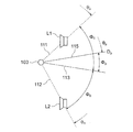
- FIG. 4 shows the positional relationship between the selected speaker and the listening position 103.
- the selected speakers are indicated by the symbols L1 and L2.
- the speaker L1 is a speaker (first speaker) located on one side (counterclockwise direction) and in the closest direction (azimuth) with respect to the target direction Dp, and the speaker L2 is in the target direction DP. On the other hand, it is a speaker (second speaker) located on the other side (clockwise direction) and in the closest direction (azimuth).
- Panning coefficients w 1, w 2 for the speaker L1, L2 is determined so as to satisfy the following formula (1a) and (1b).
- ⁇ 0 is half the angle formed by the straight line 111 connecting the listening position 103 and the speaker L1 and the straight line 112 connecting the listening position 103 and the speaker L2.
- phi p compared linear 113 dividing angle a (2 [phi 0) to two formed by the above straight line 111 and 112, the angle of the straight line 115 indicating the target direction Dp, more precisely, from the azimuth angle of the straight line 113 It is an angle obtained by subtracting the azimuth angle of the straight line 115.
- the drive signal generation unit 26 selects a pair of speakers to be used for audio output based on the angle information Gp output from the sound image direction determination unit 22, and the panning coefficients w 1 and w 2 determined by the panning ratio control unit 25. After filtering, the magnitude of the audio signal Sb is adjusted based on the above, and the drive signals Qa to Qd are output.
- speakers 15a and 15b are selected.
- As the drive signal for the selected speaker (drive signals Qa, Qb in the illustrated example), a drive signal for performing audio output by the selected speaker is generated.
- a silent signal is generated as the drive signal (drive signals Qc, Qd in the illustrated example) for the unselected speaker. "Generating a silent signal” is equivalent to not outputting a drive signal.
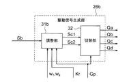
- the drive signal generation unit 26 includes, for example, an adjustment unit 31 and a switching unit 32, as shown in FIG.
- the adjusting unit 31 receives the audio signal Sb after filtering, adjusts the volume and timing, and outputs the signals Sc1 and Sc2.
- the signals Sc1 and Sc2 output from the adjusting unit 31 are referred to as adjusted signals.
- the distance from the listening position 103 to each speaker is also taken into consideration. For example, in determining the magnitude (amplitude) of the adjusted signals Sc1 and Sc2, the longer the distance, the larger the adjusted signal so as to compensate for the decrease in sound pressure due to the distance.
- the loudness (sound pressure) of the sound generated by each speaker and reaching the listening position 103 is proportional to the reciprocal of the square of the distance from the speaker to the listening position 103.
- the distance to the L2 is R 1, R 2
- coefficients m 1, m 2 used for the generation of the adjusted signals for the loudspeakers L1, L2 is the following formula It is determined to satisfy the relationship of (2a) and (2b).
- the distances Ra to Rd from the listening position 103 to the speakers 15a to 15 are known and are stored in the external storage device 11 or in a memory (not shown) in the audio signal processing device 12, and the adjusting unit 31 is selected.
- the speaker distance is used as the distances R 1 and R 2.
- the generation of the adjusted signal Sc1 is in the filtered audio signal Sb, include process of applying the coefficients w 1 and m 1, the generation of the adjusted signal Sc2 is in the filtered audio signal Sb, the coefficient w 2 and m The process of multiplying by 2 is included.
- the generation of the adjusted signals Sc1 and Sc2 further includes the addition of a delay amount.
- the delay amount is given to adjust the timing at which the speaker outputs the sound in order to cancel the difference T d of the transmission time according to the distance.
- the timing is adjusted by adjusting the time (delay time) from receiving the filtered audio signal Sb until the adjusted signals Sc1 and Sc2 are output.
- the difference T d of the above transmission time is given by the following equation (3).
- ⁇ is the speed of sound. If T d is positive, it means that the transmission time to the speaker L2 is longer , and if T d is negative, it means that the transmission time to the speaker L1 is longer.
- the delay amount is lengthened as the distance is shorter so as to compensate for the above-mentioned difference T d in transmission time. That is, the delay amount of the speaker having a short distance is controlled to be T d longer than the delay amount of the speaker having a long distance. For example, the delay amount given to the signal for the speaker having a long distance is set to zero, and the delay amount equal to the difference T d of the transmission time is given to the signal for the speaker having a short distance.
- the switching unit 32 selects a pair of speakers based on the angle information Gp, and outputs the adjusted signals Sc1 and Sc2 as drive signals to the selected speakers.
- the speakers 15a and 15b are selected, and the adjusted signals Sc1 and Sc2 are output as drive signals Qa and Qb for the speakers 15a and 15b, respectively.
- the drive signals Qa and Qb output from the drive signal generation unit 26 are converted into analog signals by the DA conversion circuit 13, amplified by the power amplifier circuit 14, and supplied to the speakers 15a and 15b.
- a silent signal (a signal indicating that no audio output is performed) is supplied to the speakers 15d and 15c that are not selected.
- the target direction Dp is within the range from the direction Da of the speaker 15a to the direction Db of the speaker 15b has been described above, but the same applies even if the target direction is in another range. That is, if the target direction Dp is within the range from the direction Db of the speaker 15b to the direction Dc of the speaker 15c, the speakers 15b and 15c are selected and used for audio output.
- the speakers 15c and 15d are selected and used for audio output.
- the speakers 15d and 15a are selected and used for audio output.
- a set of filter coefficients for each of the plurality of designated directions described above is obtained by installing an actual sound source in the designated direction and obtaining a pair of HRTFs from the actual sound source to the left and right ears of the driver 103 at the listening position.
- the ITD frequency characteristics and ILD frequency characteristics are obtained from the pair of HRTFs, the sound image is localized in the specified direction by amplitude panning, and the pair of HRTFs from the position of the sound image to the left and right ears of the driver 103 at the listening position are obtained.
- the ITD frequency characteristics and ILD frequency characteristics were obtained from the obtained pair of HRTFs, the ITD frequency characteristics and ILD frequency characteristics obtained for the actual sound source, and the ITD frequency characteristics and ILD obtained for the localized sound image. It is generated based on the frequency characteristics of.
- HRTF is an abbreviation for Head Related Transfer Function.
- the installation position of the actual sound source and the position where the sound image is localized are predetermined distances equal to each other from the listening position 103.
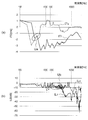
- FIG. 6A shows an example of the frequency characteristics of the ITD
- FIG. 6B shows an example of the frequency characteristics of the ILD.
- the characteristics shown in FIGS. 6 (a) and 6 (b) are characteristics when the designated direction is 90 degrees (right ear direction).
- the ITD becomes a positive value when the voice reaches the right ear slowly (the right ear has a longer transmission time).
- the ILD has a positive value when the level of speech in the left ear is high.
- the frequency characteristic ITr of ITD when the actual sound source is in the direction of 90 degrees shown in FIG. 6A and the frequency characteristic ITv and characteristics of ITD when the sound image is localized in the same direction of 90 degrees by amplitude panning. Focusing on the frequency range of 1500 Hz or less, it can be seen that the difference in ITD is small in the band of 300 to 400 Hz, as shown by the dotted line Ua. The reason for paying attention to the frequency range of 1500 Hz or less will be described later.
- the set of filter coefficients is determined so as to emphasize the frequency component in the band where the difference in ITD is relatively small and to perform filtering which emphasizes the frequency component in the band where the difference in ILD is relatively small. Be done.
- the characteristics are obtained, and the set of filter coefficients is determined based on the obtained frequency characteristics.
- the set of filter coefficients is stored in the filter coefficient storage unit 21 for each specified designated direction.
- the set of filter coefficients used for filtering is the difference in ITD between the case where the actual sound source is arranged in the target direction and the case where the sound image is localized in the target direction within the frequency range of 1500 Hz or less. Emphasizes the frequency component in a relatively small band, and in the case where the actual sound source is arranged in the target direction within the frequency range of 1500 Hz or higher, and the case where the sound image is localized in the target direction, the ILD It emphasizes the frequency components in the band where the difference is relatively small.
- the ITD and ILD when the sound image is localized in the target direction are closer to the ITD and ILD when the actual sound source is arranged in the target direction. Therefore, compared to normal amplitude panning (when filtering is not performed), the feeling that sound is being generated from the target direction becomes stronger. That is, the sense of localization of the sound image is enhanced. The reason is as follows.
- a person uses ITD at a certain frequency, for example, a frequency range of 1500 Hz or less, and ILD at a certain frequency, for example, a frequency range of 1500 Hz or more.
- the difference in ITD is relatively small between the frequency characteristics of ITD when there is a real sound source in a certain direction and the frequency characteristics of ITD when the sound image is localized in the same direction by amplitude panning. If the frequency component is emphasized, among the sounds when the sound image is localized by amplitude panning, the frequency component in the band in which the ITD is relatively close to the sound emitted from the actual sound source becomes dominant.
- the difference in ILD is relatively large in the frequency range of 1500 Hz or more. If the frequency component in a small band is emphasized, among the sounds when the sound image is localized by amplitude panning, the frequency component in a band whose ILD is relatively close to the sound emitted from the actual sound source becomes dominant.
- a band having a relatively small difference in ITD is specified in a frequency range of 1500 Hz or less, and a band having a relatively small difference in ILD is specified in a frequency range of 1500 Hz or more.
- a band having a relatively small ITD difference may be specified in a frequency range other than 1500 Hz and below a specific frequency, and a band having a relatively small difference in ILD may be specified in a range other than 1500 Hz and above a specific frequency. You may.
- the predetermined frequency within the frequency range below the predetermined frequency (upper limit frequency), a band with a relatively small difference in ITD is specified, and the difference in ILD is relatively large within the frequency range above the predetermined frequency (lower limit frequency). Only a small band should be specified.
- the upper limit frequency and the lower limit frequency may be the same.
- the frequency components of both the band in which the difference in ITD in the frequency range below the upper limit frequency is relatively small and the band in which the difference in ILD in the frequency range above the lower limit frequency is relatively small are emphasized. Instead, emphasize one frequency component in a band with a relatively small difference in ITD within the frequency range below the upper limit frequency and a band with a relatively small difference in ILD within the frequency range above the lower limit frequency.
- a set of filter coefficients may be generated so as to perform filtering that does not emphasize the other frequency component.
- the frequency component of the band where the difference in ITD is relatively small or the band where the difference in ILD is relatively small is emphasized.
- a set of filter coefficients may be generated to perform filtering to attenuate at least one frequency component in a band with a relatively large ITD difference and a band with a relatively large ILD difference.
- the above set of filter coefficients may be for performing filtering that performs both the above emphasis and attenuation.
- the degree of emphasizing does not have to be uniform. For example, the smaller the difference in ITD or the difference in ILD, the greater the degree of emphasis. Similarly, the degree of attenuation does not have to be uniform. For example, the greater the difference in ITD or the difference in ILD, the greater the degree of attenuation.
- the set of filter coefficients used in filtering may be such that at least one of the frequency components of the band in which the ITD difference is relatively small and the band in which the ILD difference is relatively small is relatively large. Just do it.
- the calculation of the panning coefficients w 1 and w 2 is not limited to the above example, and may be determined by other methods such as DBAP (Disstance Based Applied Panning) and VBAP (Vector Based Applied Panning).
- the number of speakers is not limited to four.
- the number of speakers may be 2 or more. If the number of speakers is 3 or more, the speaker (first speaker) located in the closest direction on one side (counterclockwise direction) of the target direction among the 3 or more speakers according to the target direction. , The speaker (second speaker) located closest to the other side (clockwise) of the target direction is selected, and the selected first and second speakers serve as a pair of speakers for amplitude panning. Used.
- the target direction is limited to between the two speakers, and the process of selecting speakers according to the target becomes unnecessary. Therefore, the switching unit 32 in the drive signal generation unit 26 becomes unnecessary.
- the sound image is localized in the direction of the object in order to draw the attention of the driver 103 toward the object located in the vicinity of the automobile.
- the object may be a display in the passenger compartment of an automobile. For example, by selecting one of a plurality of displays in the passenger compartment of an automobile and localizing a sound image in the direction of the selected display in order to guide the line of sight of the driver 103 to the selected display. Is also good. In this case, control may be performed so that the direction of the selected display is the target direction of the sound image.
- the object may also be one of a plurality of displays used for driving a train or the like.
- the object may also be one of a plurality of displays provided in the passenger car or the passenger cabin of the train.
- the reference listening position may be a typical position in the passenger car or the passenger car.
- the typical position may be different for each zone in the passenger car. That is, the space inside the passenger car may be divided into a plurality of zones, and the above-mentioned representative positions may be set separately for each zone. For example, the position of the center in each zone may be set as the above-mentioned representative position.
- the object may also be any one of a plurality of displays provided in the control room, the monitoring room, and the like.
- the control room may be, for example, a central control room that manages train operations.
- the reference listening position may be a representative position such as a control room or a monitoring room.
- a typical position may be a position occupied by the observer during the monitoring work, for example, a sitting position.
- the input sound source is filtered using the filter selected based on the angle information Gp from the sound image direction determination unit 22, and the amplitude panning is performed according to the angle information Gp.
- the sound image is localized around the listening position.
- the sound image may be blurred and the direction of the sound image may not be perceived accurately.
- the band in which the ITD or ILD is close to the actual sound source becomes dominant, so that an effect that the localization feeling is improved as compared with the normal amplitude panning can be obtained.
- Embodiment 2 the volume is controlled according to the distance to the sound image to give the sound image not only a sense of direction but also a sense of distance.
- FIG. 7 shows the audio signal processing device 12b of the second embodiment.
- the illustrated audio signal processing device 12b is generally the same as the audio signal processing device 12 of FIG. However, the difference is that the sound image distance determination unit 27 and the volume control unit 28 are added, and the drive signal generation unit 26b is provided instead of the drive signal generation unit 26.
- the sound image distance determination unit 27 determines the distance from the listening position 103 to the position where the sound image should be presented.
- the sound image distance determination unit 27 receives information indicating the position of the object detected by, for example, an ADAS / ECU (not shown), and sets the distance from the listening position 103 to the position of the object as the distance to the position where the sound image should be presented. Determined as Rp.
- the sound image distance determination unit 27 outputs the distance information Gr representing the determined distance Rp.
- the distance to the position where the sound image should be presented may be simply referred to as "target distance of sound image” or simply "target distance”.
- the volume control unit 28 calculates a coefficient (volume adjustment coefficient) Kr for adjusting the volume based on the distance information Gr output from the sound image distance determination unit 27.
- the volume adjustment coefficient Kr is set larger as the target distance is shorter and smaller as the target distance is longer.
- the volume adjustment coefficient Kr is calculated by, for example, the following equation (4).
- Rp is the target distance.
- R 0 is the shortest distance within the range assumed as the target distance.
- the shortest distance R 0 is, for example, the distance from the listening position 103 to the nearest window, for example, 50 cm.
- Drive signal generating unit 26b not only coefficients w 1, w 2, m 1 , m 2, also based on the volume adjustment coefficient Kr output from the volume control unit 28, generates a signal Sc1, Sc2.
- the drive signal generation unit 26b has, for example, an adjustment unit 31b and a switching unit 32 as shown in FIG. Adjusting portion 31b is the generally same as the adjusting unit 31 of FIG. 5, not only the coefficients w 1, w 2, m 1 , m 2, also based on the volume adjustment factor Kr, and generates a signal Sc1, Sc2 ..
- the adjusting unit 31b multiplies the filtered audio signal Sb by the coefficients w 1 , m 1 , and Kr, and further adds a delay amount according to the distance to the speaker L1 to give the adjusted signal Sc1.
- the delay amount for the signal for the speaker having the shorter distance is different from the delay amount for the signal for the speaker with the shorter distance. It may be made longer by T d.
- the switching unit 32 operates in the same manner as the switching unit 32 of FIG. That is, the switching unit 32 selects a pair of speakers based on the angle information Gp, and outputs the adjusted signals Sc1 and Sc2 as drive signals to the selected speakers.
- the sound image is localized at the position of the object.
- the object may be a display in the passenger compartment of an automobile. For example, by selecting one of a plurality of displays in the passenger compartment of an automobile and localizing a sound image at the position of the selected display in order to guide the line of sight of the driver 103 to the selected display. Is also good. In this case, control may be performed so that the position of the selected display becomes the position of the sound image.
- the target distance does not have to match the distance to the object (display).
- the target distance may be changed according to the importance of the information displayed on the display. Specifically, the more important the information displayed on the display is, the shorter the target distance may be.
- the object may also be one of a plurality of displays used for driving a train or the like.
- the object may also be one of a plurality of displays provided in the passenger car or the passenger cabin of the train.
- the reference listening position may be a typical position in the passenger car or the cabin.
- the typical position may be different for each zone in the passenger car. That is, the space inside the passenger car may be divided into a plurality of zones, and the above-mentioned representative positions may be set separately for each zone. For example, the position of the center in each zone may be set as the above-mentioned representative position.
- the object may also be any one of a plurality of displays provided in the control room, the monitoring room, and the like.
- the control room may be, for example, a central control room that manages train operations.
- the reference listening position may be a representative position such as a control room or a monitoring room.
- a typical position may be a position occupied by the observer during the monitoring work, for example, a sitting position.
- the same effect as that of the first embodiment can be obtained in the second embodiment.
- the effect that the distance to the sound image becomes easier to perceive can be obtained by increasing the volume as the target distance becomes shorter.
- FIG. 9 shows the audio signal processing device 12c of the third embodiment.
- the illustrated audio signal processing device 12c is generally the same as the audio signal processing device 12b of FIG. However, the difference is that the reverb effect control unit 29 and the drive signal generation unit 26c are provided instead of the volume control unit 28 and the drive signal generation unit 26b.
- the drive signal generation unit 26c also has a function of performing reverb processing on the audio signal Sb after filtering.
- the reverb processing is a processing that gives a reverberation effect to an audio signal.
- Reverb processing is realized by convolving impulse responses such as reverberation on the time axis or frequency axis.
- the reverberation is adjusted by adjusting the balance between the original sound represented by the original audio signal and the sound convoluted by the reverb processing. In general, the stronger the reverb effect, the farther the sound image is felt.
- the reverb effect control unit 29 determines the strength of the reverb effect based on the distance information Gr output from the sound image distance determination unit 27. It is determined that the longer the target distance indicated by the distance information Gr, the stronger the reverb effect, and conversely, the shorter the target distance, the weaker the reverb effect.
- the reverb effect control unit 29 outputs information (reverb control information) Rv indicating the strength of the determined reverb effect.
- the drive signal generation unit 26c has panning coefficients w 1 and w 2 output from the panning ratio control unit 25, and an adjustment coefficient m 1 according to the distance to the speaker.
- M 2 is used to adjust the volume, and the delay amount is adjusted according to the distances to the speakers L1 and L2.
- the drive signal generation unit 26c performs reverb processing according to the reverb control information Rv output from the reverb effect control unit 29.
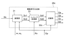
- the drive signal generation unit 26c includes an adjustment unit 31, a switching unit 32c, and a reverb processing unit 33.
- the adjusting unit 31 is the same as the adjusting unit 31 of FIG.
- the reverb processing unit 33 performs reverb processing on the signals Sc1 and Sc2 output from the adjustment unit 31, and outputs the signals Sd1 and Sd2 after the reverb processing.
- the strength of the reverb effect is determined according to the reverb control information Rv from the reverb effect control unit 29.
- the reverb processing given to the signals Sc1 and Sc2 may have the same contents or may be different from each other.
- the switching unit 32c is the same as the switching unit 32 of FIG. 5, but the outputs Sd1 and Sd2 of the reverb processing unit 33 are used as the drive signals for the selected speaker instead of the outputs Sc1 and Sc2 of the adjusting unit 31. Output.
- the reverb processing unit 33 may be provided in the front stage of the adjusting unit 31. If it is provided in the previous stage, the audio signal Sb is subjected to reverb processing after filtering, and then two signals are generated by the adjusting unit 31.
- the same effect as that of the first embodiment can be obtained in the third embodiment.
- the third embodiment by changing the strength of the reverb effect according to the target distance, the effect that the distance to the sound image can be easily perceived can be obtained.
- FIG. 11 shows the audio signal processing device 12d of the fourth embodiment.
- the audio signal processing device 12d shown in FIG. 11 is generally the same as the audio signal processing device 12b of FIG. 7, but a reverb effect control unit 29 is added, and a drive signal generation unit 26b is added instead of the drive signal generation unit 26b. It can be seen that the portion 26d is provided.
- the audio signal processing device 12d shown in FIG. 11 is generally the same as the audio signal processing device 12c of FIG. 9, but a volume control unit 28 is added, and instead of the drive signal generation unit 26c, a drive signal generation unit is added. It can be seen that 26d is provided.
- the drive signal generation unit 26d can adjust the volume according to the distance as in the drive signal generation unit 26b of the second embodiment, and can adjust the volume according to the distance as in the drive signal generation unit 26c of the third embodiment.
- Reverb processing can be performed.
- the drive signal generation unit 26d includes an adjustment unit 31b, a switching unit 32c, and a reverb processing unit 33.
- the adjusting unit 31b is the same as the adjusting unit 31b in FIG.
- the reverb processing unit 33 is the same as the reverb processing unit 33 of FIG.
- the switching unit 32c is the same as the switching unit 32c in FIG.
- the reverb processing unit 33 may be provided in front of the adjustment unit 31b in the same manner as described in the third embodiment.
- a part or all of the audio signal processing apparatus described in the first to fourth embodiments may be composed of a processing circuit.
- the functions of each part of the audio signal processing device may be realized by separate processing circuits, or the functions of a plurality of parts may be collectively realized by one processing circuit.
- the processing circuit may be composed of hardware or software, that is, a programmed computer. Of the functions of each part of the audio signal processing device, a part may be realized by hardware and the other part may be realized by software.
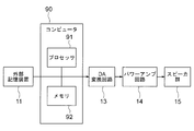
- FIG. 13 shows a computer 90 that realizes all the functions of the audio signal processing device, together with an external storage device 11, a DA conversion circuit 13, a power amplifier circuit 14, and a speaker group 15.
- the computer 90 has a processor 91 and a memory 92.
- the processor 91 uses, for example, a CPU (Central Processing Unit), a GPU (Graphics Processing Unit), a microprocessor, a microcontroller, a DSP (Digital Signal Processor), or the like.
- a CPU Central Processing Unit
- GPU Graphics Processing Unit
- microprocessor a microcontroller
- DSP Digital Signal Processor
- the memory 92 includes, for example, a RAM (Random Access Memory), a ROM (Read Only Memory), a flash memory, an EPROM (Erasable Programmable Lead Only Memory) or an EPROM (Electrically Memory Memory Memory Memory), an EEPROM (Electrically Memory Memory, etc.) Alternatively, a photomagnetic disk or the like is used. A part or all of the memory 92 may be composed of a part of the external storage device 11.
- the processor 91 and the memory 92 may be realized by an LSI (Large Scale Integration) integrated with each other.
- the processor 91 realizes the function of the audio signal processing device by loading the program into the memory 92 and executing the program loaded in the memory 92.
- Functions of the audio signal processor include filtering on the input audio signal and amplitude panning on the filtered signal.
- the program may be provided over a network or may be recorded and provided on a recording medium, such as a non-temporary recording medium. That is, the program may be provided, for example, as a program product.
- the computer of FIG. 13 includes a single processor, but may include two or more processors.
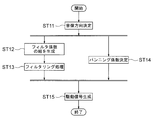
- the processing procedure by the processor 91 when the audio signal processing device 12 of FIG. 3 is configured by the computer of FIG. 13 will be described with reference to FIG.
- the process of FIG. 14 is started at predetermined processing cycles.
- step ST11 the processor 91 determines the target direction Dp of the sound image.
- the process of step ST11 corresponds to the process of the sound image direction determination unit 22 in FIG.
- step ST12 the processor 91 generates a set of filter coefficients based on the target direction Dp determined in step ST11.
- the process of step ST12 corresponds to the process of the filter coefficient generation unit 23 of FIG.
- step ST13 the processor 91 performs a filtering process using the set of filter coefficients generated in step ST13.
- the processing in step ST13 corresponds to the processing in the filtering processing unit 24 of FIG.
- step ST14 the processor 91 determines the panning ratio based on the target direction Dp determined in step ST11.
- the process of step ST14 corresponds to the process of the panning ratio control unit 25 of FIG.
- step ST14 can be performed in parallel with the process of steps ST12 and ST13.
- step ST15 the processor 91 performs the processing of step ST15.
- step ST15 amplitude panning is performed on the signal filtered in step ST13 using the panning ratio determined in step ST14. Further, in step ST15, the speaker is selected and the drive signal for the selected speaker is generated based on the target direction Dp determined in step ST11.
- the process of step ST15 corresponds to the process of the drive signal generation unit 26 of FIG.
- step ST21 the processor 91 determines the target distance to the sound image.
- the process of step ST21 corresponds to the process of the sound image distance determination unit 27 of FIG.
- step ST22 the processor 91 calculates the volume adjustment coefficient Kr based on the target distance determined in step ST21.
- the process of step ST22 corresponds to the process of the volume control unit 28 of FIG.
- steps ST21 and ST22 can be performed in parallel with the processing of steps ST11 to ST14.
- the processor 91 performs the process of step ST15b.
- step ST15b amplitude panning is performed on the signal filtered in step ST13 using the panning ratio determined in step ST14. Further, in step ST15b, the speaker is selected and the drive signal for the selected speaker is generated based on the target direction Dp determined in step ST11 and the volume adjustment coefficient Kr calculated in step ST22.
- the process of step ST15b corresponds to the process of the drive signal generation unit 26b of FIG.
- the procedure of processing by the processor 91 when the audio signal processing device 12c of FIG. 9 is configured by the computer of FIG. 13 will be described with reference to FIG.
- the processing of FIG. 16 is started at predetermined processing cycles.
- step ST15 is replaced by step ST15c
- step ST22 is replaced by step ST31.
- step ST31 the processor 91 determines the strength of the reverb effect based on the target distance determined in step ST21.
- the process of step ST31 corresponds to the process of the reverb effect control unit 29 of FIG.
- steps ST21 and ST31 can be performed in parallel with the processing of steps ST11 to ST14.
- the processor 91 performs the process of step ST15c.
- step ST15c amplitude panning is performed on the signal filtered in step ST13 using the panning ratio determined in step ST14. Further, in step ST15c, the speaker is selected and the drive signal for the selected speaker is generated based on the target direction Dp determined in step ST11 and the strength of the reverb effect determined in step ST31.
- the process of step ST15c corresponds to the process of the drive signal generation unit 26c of FIG.
- the processing procedure shown in FIG. 17 is generally the same as the processing procedure shown in FIG. 15, and can be seen as different in that step ST31 is added and step ST15b is replaced by step ST15d.
- the procedure is generally the same as that shown in FIG. 16, and it can be seen that step ST22 is added and step ST15c is replaced by step ST15d.
- Step ST22 is the same as step ST22 in FIG.
- Step ST31 is the same as step ST31 in FIG.
- the process of step ST22 and the process of step ST31 can be performed in parallel.
- the processor 91 performs the process of step ST15d.
- step ST15d amplitude panning is performed on the signal filtered in step ST13 using the panning ratio determined in step ST14.
- step ST15d the speaker selection and the selected speaker are further based on the target direction Dp determined in step ST11, the volume adjustment coefficient Kr calculated in step ST22, and the strength of the reverb effect determined in step ST31.
- the drive signal for is generated.
- the process of step ST15d corresponds to the process of the drive signal generation unit 26d of FIG.
- the audio signal processing device has been explained above. It is possible to implement the audio signal processing method with the above audio signal processing device. Such an audio signal processing method can also be implemented by the above-mentioned processing circuit.
- External storage device 12, 12b, 12c, 12d Audio signal processing device, 13 DA conversion circuit, 14 power amplifier circuit, 15 speaker group, 21 filter coefficient storage unit, 22 sound image direction determination unit, 23 filter coefficient generation unit, 24 Filtering processing unit, 25 panning ratio control unit, 26, 26b, 26c, 26d drive signal generation unit, 27 sound image distance determination unit, 28 volume control unit, 29 reverb effect control unit, 31, 31b adjustment unit, 32, 32c switching unit , 33 reverb processing unit, 90 computer, 91 processor, 92 memory.
Landscapes
- Physics & Mathematics (AREA)
- Engineering & Computer Science (AREA)
- Acoustics & Sound (AREA)
- Signal Processing (AREA)
- Stereophonic System (AREA)
- Circuit For Audible Band Transducer (AREA)
Priority Applications (2)
| Application Number | Priority Date | Filing Date | Title |
|---|---|---|---|
| JP2022513798A JP7199601B2 (ja) | 2020-04-09 | 2020-04-09 | 音声信号処理装置及び音声信号処理方法、並びにプログラム及び記録媒体 |
| PCT/JP2020/015961 WO2021205601A1 (ja) | 2020-04-09 | 2020-04-09 | 音声信号処理装置及び音声信号処理方法、並びにプログラム及び記録媒体 |
Applications Claiming Priority (1)
| Application Number | Priority Date | Filing Date | Title |
|---|---|---|---|
| PCT/JP2020/015961 WO2021205601A1 (ja) | 2020-04-09 | 2020-04-09 | 音声信号処理装置及び音声信号処理方法、並びにプログラム及び記録媒体 |
Publications (1)
| Publication Number | Publication Date |
|---|---|
| WO2021205601A1 true WO2021205601A1 (ja) | 2021-10-14 |
Family
ID=78023101
Family Applications (1)
| Application Number | Title | Priority Date | Filing Date |
|---|---|---|---|
| PCT/JP2020/015961 Ceased WO2021205601A1 (ja) | 2020-04-09 | 2020-04-09 | 音声信号処理装置及び音声信号処理方法、並びにプログラム及び記録媒体 |
Country Status (2)
| Country | Link |
|---|---|
| JP (1) | JP7199601B2 (https=) |
| WO (1) | WO2021205601A1 (https=) |
Cited By (2)
| Publication number | Priority date | Publication date | Assignee | Title |
|---|---|---|---|---|
| US20230012320A1 (en) * | 2021-07-09 | 2023-01-12 | Yamaha Corporation | Signal generating apparatus, vehicle, and computer-implemented method of generating signals |
| JP2024007669A (ja) * | 2022-07-06 | 2024-01-19 | Kddi株式会社 | 音源及び受音体の位置情報を用いた音場再生プログラム、装置及び方法 |
Citations (3)
| Publication number | Priority date | Publication date | Assignee | Title |
|---|---|---|---|---|
| JP2004187300A (ja) * | 2002-12-03 | 2004-07-02 | Bose Corp | 指向性電気音響変換 |
| JP2017046322A (ja) * | 2015-08-28 | 2017-03-02 | キヤノン株式会社 | 信号処理装置及びその制御方法 |
| JP2017513382A (ja) * | 2014-03-24 | 2017-05-25 | サムスン エレクトロニクス カンパニー リミテッド | 音響信号のレンダリング方法、該装置、及びコンピュータ可読記録媒体 |
-
2020
- 2020-04-09 JP JP2022513798A patent/JP7199601B2/ja active Active
- 2020-04-09 WO PCT/JP2020/015961 patent/WO2021205601A1/ja not_active Ceased
Patent Citations (3)
| Publication number | Priority date | Publication date | Assignee | Title |
|---|---|---|---|---|
| JP2004187300A (ja) * | 2002-12-03 | 2004-07-02 | Bose Corp | 指向性電気音響変換 |
| JP2017513382A (ja) * | 2014-03-24 | 2017-05-25 | サムスン エレクトロニクス カンパニー リミテッド | 音響信号のレンダリング方法、該装置、及びコンピュータ可読記録媒体 |
| JP2017046322A (ja) * | 2015-08-28 | 2017-03-02 | キヤノン株式会社 | 信号処理装置及びその制御方法 |
Cited By (5)
| Publication number | Priority date | Publication date | Assignee | Title |
|---|---|---|---|---|
| US20230012320A1 (en) * | 2021-07-09 | 2023-01-12 | Yamaha Corporation | Signal generating apparatus, vehicle, and computer-implemented method of generating signals |
| US12010503B2 (en) * | 2021-07-09 | 2024-06-11 | Yamaha Corporation | Signal generating apparatus, vehicle, and computer-implemented method of generating signals |
| US20240223989A1 (en) * | 2021-07-09 | 2024-07-04 | Yamaha Corporation | Signal generating apparatus, vehicle, and computer-implemented method of generating signals |
| US12219343B2 (en) * | 2021-07-09 | 2025-02-04 | Yamaha Corporation | Signal generating apparatus, vehicle, and computer-implemented method of generating signals |
| JP2024007669A (ja) * | 2022-07-06 | 2024-01-19 | Kddi株式会社 | 音源及び受音体の位置情報を用いた音場再生プログラム、装置及び方法 |
Also Published As
| Publication number | Publication date |
|---|---|
| JP7199601B2 (ja) | 2023-01-05 |
| JPWO2021205601A1 (https=) | 2021-10-14 |
Similar Documents
| Publication | Publication Date | Title |
|---|---|---|
| JP7566686B2 (ja) | 個々のサウンド領域を提供するための装置および方法 | |
| US9264834B2 (en) | System for modifying an acoustic space with audio source content | |
| US9930468B2 (en) | Audio system phase equalization | |
| JP6130599B2 (ja) | 第1および第2の入力チャネルを少なくとも1個の出力チャネルにマッピングするための装置及び方法 | |
| JP5323055B2 (ja) | 車両における音の有指向放射(directionallyradiatingsoundinavehicle) | |
| CN106464299B (zh) | 管理车辆音频平台中的电话和娱乐音频 | |
| KR102785284B1 (ko) | 다채널 오디오에 응답하여 적어도 하나의 피드백 지연 네트워크를 이용한 바이노럴 오디오의 생성 | |
| EP2550813B1 (en) | Multichannel sound reproduction method and device | |
| EP2716075B1 (en) | An audio system and method therefor | |
| JP3505085B2 (ja) | オーディオ装置 | |
| JP2012503943A (ja) | モノフォニック対応およびラウドスピーカ対応のバイノーラルフィルタ | |
| CN108737930B (zh) | 车辆导航系统中的可听提示 | |
| EP4175325B1 (en) | Method for audio processing | |
| US20220078570A1 (en) | Method for generating binaural signals from stereo signals using upmixing binauralization, and apparatus therefor | |
| WO2021205601A1 (ja) | 音声信号処理装置及び音声信号処理方法、並びにプログラム及び記録媒体 | |
| JP6452377B2 (ja) | スピーカ配置選択装置、スピーカ配置選択方法及び音場制御システム | |
| US8009834B2 (en) | Sound reproduction apparatus and method of enhancing low frequency component | |
| JP2004064739A (ja) | 音像制御システム | |
| US12219343B2 (en) | Signal generating apparatus, vehicle, and computer-implemented method of generating signals | |
| EP3761674A1 (en) | Audio signal processing apparatus, audio signal processing method, and audio signal processing program | |
| JP2020163936A (ja) | 音響処理装置、音響処理方法、及びプログラム | |
| JP2009147815A (ja) | 音響空間制御装置及び音響空間制御方法 | |
| JP2011228956A (ja) | 車載用音場制御装置 | |
| JP2007019940A (ja) | 音場制御装置 | |
| US11778369B2 (en) | Notification apparatus, notification method, and program |
Legal Events
| Date | Code | Title | Description |
|---|---|---|---|
| 121 | Ep: the epo has been informed by wipo that ep was designated in this application |
Ref document number: 20930583 Country of ref document: EP Kind code of ref document: A1 |
|
| ENP | Entry into the national phase |
Ref document number: 2022513798 Country of ref document: JP Kind code of ref document: A |
|
| NENP | Non-entry into the national phase |
Ref country code: DE |
|
| 122 | Ep: pct application non-entry in european phase |
Ref document number: 20930583 Country of ref document: EP Kind code of ref document: A1 |