WO2021205515A1 - 列車検知装置、列車検知システム、および列車検知方法 - Google Patents
列車検知装置、列車検知システム、および列車検知方法 Download PDFInfo
- Publication number
- WO2021205515A1 WO2021205515A1 PCT/JP2020/015546 JP2020015546W WO2021205515A1 WO 2021205515 A1 WO2021205515 A1 WO 2021205515A1 JP 2020015546 W JP2020015546 W JP 2020015546W WO 2021205515 A1 WO2021205515 A1 WO 2021205515A1
- Authority
- WO
- WIPO (PCT)
- Prior art keywords
- train
- train detection
- detection device
- detection sensor
- block section
- Prior art date
- Legal status (The legal status is an assumption and is not a legal conclusion. Google has not performed a legal analysis and makes no representation as to the accuracy of the status listed.)
- Ceased
Links
Images







Classifications
-
- B—PERFORMING OPERATIONS; TRANSPORTING
- B61—RAILWAYS
- B61L—GUIDING RAILWAY TRAFFIC; ENSURING THE SAFETY OF RAILWAY TRAFFIC
- B61L1/00—Devices along the route controlled by interaction with the vehicle or train
- B61L1/18—Railway track circuits
-
- B—PERFORMING OPERATIONS; TRANSPORTING
- B61—RAILWAYS
- B61L—GUIDING RAILWAY TRAFFIC; ENSURING THE SAFETY OF RAILWAY TRAFFIC
- B61L23/00—Control, warning or like safety means along the route or between vehicles or trains
- B61L23/08—Control, warning or like safety means along the route or between vehicles or trains for controlling traffic in one direction only
- B61L23/14—Control, warning or like safety means along the route or between vehicles or trains for controlling traffic in one direction only automatically operated
- B61L23/16—Track circuits specially adapted for section blocking
-
- B—PERFORMING OPERATIONS; TRANSPORTING
- B61—RAILWAYS
- B61L—GUIDING RAILWAY TRAFFIC; ENSURING THE SAFETY OF RAILWAY TRAFFIC
- B61L3/00—Devices along the route for controlling devices on the vehicle or train, e.g. to release brake or to operate a warning signal
- B61L3/02—Devices along the route for controlling devices on the vehicle or train, e.g. to release brake or to operate a warning signal at selected places along the route, e.g. intermittent control simultaneous mechanical and electrical control
- B61L3/08—Devices along the route for controlling devices on the vehicle or train, e.g. to release brake or to operate a warning signal at selected places along the route, e.g. intermittent control simultaneous mechanical and electrical control controlling electrically
- B61L3/12—Devices along the route for controlling devices on the vehicle or train, e.g. to release brake or to operate a warning signal at selected places along the route, e.g. intermittent control simultaneous mechanical and electrical control controlling electrically using magnetic or electrostatic induction; using radio waves
Definitions
- This disclosure relates to a train detection device, a train detection system, and a train detection method for detecting the position of a train.
- Patent Document 1 sets a plurality of sections on the track, provides an axle detection device at the boundary of each section, the number of axles of the train entering each section, and exiting from each section. A technique for detecting the position of a train while reducing installation costs and maintenance costs by counting the number of axles of the train is disclosed.
- the present disclosure has been made in view of the above, and an object of the present disclosure is to obtain a train detection device capable of detecting the position of a train while avoiding a situation in which train operation is interrupted.
- the train detection device of the present disclosure is connected to a plurality of train detection sensors that are installed on the track on which the train travels and can detect the train, and from the plurality of train detection sensors.
- a sensor connection unit that acquires a signal that can determine whether or not a train has been detected and a plurality of closed sections with the train detection sensor at both ends are set on the track, and whether or not a train is present in each closed section is determined. It is characterized by including a detection unit for detecting.
- the train detection device has the effect of being able to detect the position of the train while avoiding the situation where the train operation is interrupted.
- FIG. 3 is a third diagram showing a state of each block section in the train detection system according to the first embodiment.
- the figure which shows the example of the case where the processing circuit included in the train detection apparatus which concerns on Embodiment 1 is configured by a processor and a memory.
- FIG. 1 is a diagram showing a configuration example of the train detection system 100 according to the first embodiment.
- the train detection system 100 includes a train detection device 1, a ground device 2, train detection sensors 3a to 3e, traffic lights 4a to 4e, a track 5, and a train 6.
- block sections A to D are provided on the track 5 on which the train 6 travels.
- the traveling direction of the train 6 is the direction of traveling to the right as shown by the arrow in FIG. The same shall apply in the following figures.
- the train detection device 1 detects the presence of the train 6 in each block section. The detailed configuration and operation of the train detection device 1 will be described later.
- the ground device 2 controls the traffic lights 4a to 4e based on the determination result of the presence or absence of the train 6 in each block section within the jurisdiction of the train detection device 1, and also controls a switch (not shown).
- the ground device 2 is, for example, an interlocking device, a blocking device, or the like.
- the train detection sensors 3a to 3e are sensors that are installed on the track 5 on which the train 6 travels and detect the passage of the train 6, that is, the train 6 is detected.
- the train detection sensors 3a to 3e are, for example, an axle detection sensor that counts the number of axles of the train 6 that has passed, a laser that detects the passage of the train 6, and the like.
- the train detection device 1 can perform the laser light in the order in which the laser light is cut off. It is possible to determine from which direction the train 6 has traveled.
- the train detection sensors 3a to 3e may be ground elements that detect the train 6 by communicating with the on-board element mounted on the train 6.
- a method may be used in which the on-board child notifies the existence of the train 6 and the ground element detects the train 6 when the ground element receives the notification from the on-board child.
- the train detection sensor 3 may be referred to.
- Traffic lights 4a to 4e are installed at the boundary of each block section.
- the traffic lights 4a to 4e give a progress indication or a stop indication to the train 6 under the control of the ground device 2.
- "G” shown in FIG. 1 is a progress indicator that allows the train 6 to enter.
- "R” shown in FIG. 2 and the like later is a stop indication for stopping the train 6.
- the track 5 is a route on which the train 6 travels, for example, a rail. Train 6 travels on track 5. Regarding train 6, it is assumed that the case of being composed of a plurality of vehicles and the case of a single train consisting of one vehicle are included.
- the number of block sections for detecting the position of the train 6 is four, but this is an example and is not limited to this.
- the number of block sections for which the position of the train 6 is detected may be three or less, or five or more, as long as there are a plurality of block sections.
- the configuration of the train detection device 1 will be described.
- the train detection device 1 includes a sensor connection unit 11, a detection unit 12, and a control unit 13.
- the sensor connection unit 11 connects to the train detection sensors 3a to 3e and acquires a signal capable of determining whether or not the train 6 has been detected from the train detection sensors 3a to 3e.
- the sensor connection unit 11 may output the content of the acquired signal to the detection unit 12, or may output the acquired signal itself to the detection unit 12.
- the detection unit 12 sets a plurality of block sections having train detection sensors 3a to 3e at both ends in the track 5, and detects whether or not the train 6 is present in each block section. Specifically, the detection unit 12 manages the presence of trains 6 in the block section by the logic of check-in and check-out based on the detection states of the two train detection sensors 3 installed at both ends of each block section. can do.
- the control unit 13 causes the ground device 2 to control the traffic lights 4a to 4e, a switch (not shown), and the like based on the determination result of the presence / absence of the train 6 in each block section by the detection unit 12.
- FIG. 2 is a first diagram showing a state of each block section in the train detection system 100 according to the first embodiment.
- the train detection device 1, the ground device 2, and the wiring from the ground device 2 to the traffic lights 4a to 4e are omitted.
- FIG. 2 shows a state in which all the train detection sensors 3a to 3e are operating normally. In this case, in the train detection device 1, the detection unit 12 sets the block sections A to D using the train detection sensors 3a to 3e.
- the detection unit 12 sets a block section A having the train detection sensor 3a as one end and the train detection sensor 3b as the other end, and the detection unit 12 has the train detection sensor 3b as one end and the train detection sensor 3c as the other end.
- the detection unit 12 sets a block section C having the train detection sensor 3c as one end and the train detection sensor 3d as the other end, and a block section D having the train detection sensor 3d as one end and the train detection sensor 3e as the other end.
- the detection unit 12 uses the train detection sensors 3 at both ends of the block section to indicate the number of axles of the train 6 that has entered the block section and the train 6 that has left the block section. If the number of axles is the same, it is determined that the train 6 is not in the block section. If the number of axles of the train 6 that has entered the block section is greater than the number of axles of the train 6 that has exited the block section, the detection unit 12 determines that the train 6 is in the block section. do.
- the detection unit 12 detects the entry of the train 6 into the block section by one train detection sensor 3 in the train detection sensors 3 at both ends of the block section, and detects the other train.
- the sensor 3 detects the exit of the train 6 from the block section, it is determined that the train 6 is not present in the block section. If one train detection sensor 3 detects the entry of the train 6 into the block section and the other train detection sensor 3 does not detect the exit of the train 6 from the block section, the detection unit 12 enters the block section. It is determined that the train 6 is on the line.
- the detection unit 12 detects the entry of the train 6 into the block section by one train detection sensor 3 in the train detection sensors 3 at both ends of the block section, and the other train.
- the detection sensor 3 detects the exit of the train 6 from the block section, it is determined that the train 6 is not present in the block section. If one train detection sensor 3 detects the entry of the train 6 into the block section and the other train detection sensor 3 does not detect the exit of the train 6 from the block section, the detection unit 12 enters the block section. It is determined that the train 6 is on the line.
- the detection unit 12 detects that the train 6 is in the block section D, so that the control unit 13 and the ground device 2 are prevented from entering the block section D by the following trains.
- the traffic light 4d is stopped and displayed via the signal.
- FIG. 3 is a second diagram showing a state of each block section in the train detection system 100 according to the first embodiment.
- the train detection device 1 the ground device 2, and the wiring from the ground device 2 to the traffic lights 4a to 4e are omitted.
- FIG. 3 shows a state immediately after the train detection sensor 3c fails.
- the detection unit 12 receives either a signal indicating a state when the train 6 is not detected or a signal indicating a state when the train 6 is detected from the train detection sensor 3. If the above is obtained, it can be determined that the train detection sensor 3 is operating normally.
- the detection unit 12 when the detection unit 12 has not acquired either the signal indicating the state when the train 6 is not detected and the signal indicating the state when the train 6 is being detected from the train detection sensor 3. It is determined that the train detection sensor 3 has failed. When the detection unit 12 periodically transmits a signal indicating that the train detection sensor 3 is operating normally, the detection unit 12 determines that the train detection sensor 3 has failed when the signal cannot be received. Can be done. Further, when the train detection sensor 3 is composed of an on-board element mounted on the train 6 and a ground element installed on the ground, the train detection is performed when the train 6 cannot acquire a signal from the ground element at a specified position.
- the device 1 may be notified by a method such as wireless communication that the ground element, which is a part of the train detection sensor 3, is out of order.
- the method by which the detection unit 12 determines the failure of the train detection sensor 3 is not limited to these, and other methods may be used.
- the detection unit 12 manages the presence of the train 6 for the block section B having the train detection sensor 3c at the other end and the block section C having the train detection sensor 3c at one end. I can't.
- the detection unit 12 determines that the train 6 is present in the block sections B and C, and the control unit 13 prevents the following train from entering the block section B. And the traffic light 4b is stopped and displayed via the ground device 2.
- the train detection system 100 cannot resume the operation of the train 6 in the state shown in FIG.
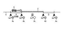
- FIG. 4 is a third diagram showing a state of each block section in the train detection system 100 according to the first embodiment.
- the train detection device 1, the ground device 2, and the wiring from the ground device 2 to the traffic lights 4a to 4e are omitted.
- FIG. 4 shows a state in which the detection unit 12 merges the blockage sections B and C to set a new blockage section Z.
- the detection unit 12 cancels the settings of the block sections B and C, and newly sets the block section Z having the train detection sensor 3b as one end and the train detection sensor 3d as the other end.
- the detection unit 12 uses the number of axles counted by the train detection sensor 3b and the number of axles counted by the train detection sensor 3d to obtain the train 6 in the closed section Z. It is possible to determine the presence or absence of an existing line. As a result, the train detection device 1 can determine the presence of the train 6 in the block section provided on the track 5, so that the position of the train 6 can be continuously determined while avoiding the situation where the operation of the train 6 is interrupted. Can be detected.
- the train detection system 100 can continue the operation of the train 6 even when the detection unit 12 of the train detection device 1 detects the failure of the train detection sensor 3, but the failed train detection sensor 3 needs to be repaired or replaced. There is. Therefore, when the detection unit 12 of the train detection device 1 detects the failure of the train detection sensor 3, the detection unit 12 may notify the user that the train detection sensor 3 has failed. Regarding the notification method, the detection unit 12 of the train detection device 1 may use a display unit such as an LCD (Liquid Crystal Display) (not shown) to indicate that the train detection sensor 3 has failed, or an LED (Light) (not shown).
- LCD Liquid Crystal Display
- Emitting (Deode) or the like may be emitted to notify the occurrence of an abnormality, or an alarm may be issued using a speaker (not shown) or the like.
- the user can grasp that the train detection sensor 3 has failed, and can repair or replace the train detection sensor 3 at a time zone when the train 6 does not pass after the operation of the train 6 on the day ends.
- FIG. 5 is a flowchart showing the operation of the train detection device 1 according to the first embodiment.
- the sensor connection unit 11 acquires a signal indicating a detection state or the like from each train detection sensor 3 (step S1).
- the detection unit 12 determines whether or not each train detection sensor 3 has a failure by using the signal acquired by the sensor connection unit 11 (step S2).
- step S2 No
- the detection unit 12 sets the block section using all the preset train detection sensors 3 (step S3).
- the detection unit 12 When there is a failure in the train detection sensor 3 (step S2: Yes), the detection unit 12 does not use the failed train detection sensor 3 and sets a block section using another train detection sensor 3 (step S4). .. Specifically, the detection unit 12 sets a first block section having a first train detection sensor as one end and a second train detection sensor as the other end, and a third train detection sensor as one end. When the use of the second train detection sensor is stopped when the second block section with the train detection sensor as the other end is set, the first train detection sensor is used as one end and the third train detection sensor is used. A third block section to be the other end is set. In the examples of FIGS.
- the blockage section B is the first blockage section
- the blockage section C is the second blockage section
- the blockage section Z is the third blockage section.
- the detection unit 12 notifies the user that the failure of the train detection sensor 3 has been detected (step S5).
- the train detection device 1 periodically repeats the operation of the flowchart shown in FIG.
- the detection unit 12 of the train detection device 1 detects the failure of the train detection sensor 3
- the application of the train detection device 1 is not limited to this.
- the detection unit 12 of the train detection device 1 can perform the same operation as described above even when the train detection sensor 3 that cannot be used in advance due to replacement or maintenance of the train detection sensor 3 is known.
- the train detection device 1 manages the presence of the train 6 in a short block section by using all the train detection sensors 3 during the time when the number of trains 6 is large, such as during the morning and evening rush hours, and operates the train 6 such as in the daytime.
- the train detection device 1 can reduce the processing load by reducing the number of block sections. Further, the train detection device 1 detects whether or not the train 6 is present in the station yard on a local line where the number of trains 6 is small, and whether or not the train 6 is present in the single track section between the stations. It can also be applied to such applications.
- FIG. 6 is a diagram showing a state of each block section when the train detection device 1 according to the first embodiment is applied to a system including an automatic train control device and a train detection device.
- the train detection device 1 uses the original block sections B, C, and D because the loop lines of the block sections B and D can be used even when the loop line of the block section C cannot be used due to a failure or the like.
- a new blockage section Y can be set.
- the train detection device 1 can determine the presence of the train 6 in the block section provided on the track 5 as in the above-mentioned case, so that the train 6 can be continuously operated while avoiding the situation where the operation of the train 6 is interrupted.
- the current position of the train 6 can be detected.
- the train detection device 1 detects a failure of the train detection sensor 3, it is assumed that one or more trains 6 are present in the block section with the failed train detection sensor 3 as a boundary. ..
- the user who has been notified by the train detection device 1 that the train detection sensor 3 has failed may go to the site to guide the train 6 and leave the newly set block section. good.
- the user who receives the notification from the train detection device 1 that the train detection sensor 3 has failed uses a train for confirming whether or not the train 6 can be normally detected in the newly set block section. Confirmation may be performed.
- the train detection sensor 3 is restored by repair or replacement, the user can normally detect the train 6 in the block section returned to the original block section setting by the train detection device 1. Confirmation may be performed using a confirmation train.
- the sensor connection unit 11 is an interface circuit capable of communicating with the train detection sensor 3.
- the detection unit 12 and the control unit 13 are realized by a processing circuit.
- the processing circuit may be a processor and memory for executing a program stored in the memory, or may be dedicated hardware.
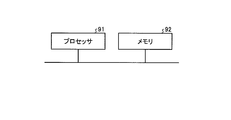
- FIG. 7 is a diagram showing an example in which the processing circuit included in the train detection device 1 according to the first embodiment is configured by a processor and a memory.
- the processing circuit is composed of the processor 91 and the memory 92, each function of the processing circuit of the train detection device 1 is realized by software, firmware, or a combination of software and firmware.
- the software or firmware is written as a program and stored in the memory 92.
- each function is realized by the processor 91 reading and executing the program stored in the memory 92. That is, the processing circuit includes a memory 92 for storing a program in which the processing of the train detection device 1 is eventually executed. It can also be said that these programs cause a computer to execute the procedure and method of the train detection device 1.
- the processor 91 may be a CPU (Central Processing Unit), a processing device, an arithmetic unit, a microprocessor, a microcomputer, a DSP (Digital Signal Processor), or the like.
- the memory 92 includes, for example, non-volatile or volatile such as RAM (Random Access Memory), ROM (Read Only Memory), flash memory, EPROM (Erasable Programmable ROM), and EEPROM (registered trademark) (Electrically EPROM).
- RAM Random Access Memory
- ROM Read Only Memory
- flash memory e.g., EPROM (Erasable Programmable ROM), and EEPROM (registered trademark) (Electrically EPROM).
- Semiconductor memory magnetic disk, flexible disk, optical disk, compact disk, mini disk, DVD (Digital Versatile Disc), etc. are applicable.
- FIG. 8 is a diagram showing an example in which the processing circuit included in the train detection device 1 according to the first embodiment is configured by dedicated hardware.
- the processing circuit is composed of dedicated hardware
- the processing circuit 93 shown in FIG. 8 includes, for example, a single circuit, a composite circuit, a programmed processor, a parallel programmed processor, an ASIC (Application Specific Integrated Circuit), and the like. FPGA (Field Programmable Gate Array) or a combination of these is applicable.
- Each function of the train detection device 1 may be realized by the processing circuit 93 for each function, or each function may be collectively realized by the processing circuit 93.
- the functions of the train detection device 1 may be realized by dedicated hardware, and some may be realized by software or firmware.
- the processing circuit can realize each of the above-mentioned functions by the dedicated hardware, software, firmware, or a combination thereof.
- the train detection device 1 when the train detection device 1 detects a failure of the train detection sensor 3, a new block is created by merging the block sections having the failed train detection sensor 3 as a boundary. It was decided to set the section. As a result, the train detection device 1 can detect the position of the train 6 while avoiding the situation where the operation of the train 6 is interrupted and without increasing the installation cost and the maintenance cost.
- the train detection device 1 of the present embodiment can be applied to fields other than railways. For example, it can be applied to manage the position of a moving body traveling on a specified route.
- the moving body traveling on the specified route may be, for example, a physical distribution collection / delivery vehicle moving in the warehouse, a bus traveling in a specific area, or the like.
- Embodiment 2 In the first embodiment, one train detection device 1 detects the presence of the train 6 in each block section set on the track 5. However, when the operation route of the train 6 is a long distance, if one train detection device 1 detects the train 6 in all the block sections set in the track 5 of the operation route of the train 6, the number of the block sections Increases and the processing load increases. In the second embodiment, a case where a plurality of train detection devices cooperate to detect the presence of the train 6 will be described.
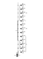
- FIG. 9 is a diagram showing a configuration example of the train detection system 100a according to the second embodiment.
- the train detection system 100a includes train detection devices 7a to 7c, ground devices 2a to 2c, train detection sensors 3a to 3m, traffic lights 4a to 4m, track 5, and train 6.
- block sections A to L are provided on the track 5 on which the train 6 travels.
- the train detection device 7a is a first train detection device that detects whether or not a train 6 is present in a jurisdiction range 71, which is a first jurisdiction range composed of a plurality of block sections A to D.
- the train detection device 7b is a second train detection device that detects whether or not a train 6 is present in a jurisdiction range 72, which is a second jurisdiction range composed of a plurality of block sections E to H.
- the train detection device 7c is a third train detection device that detects whether or not a train 6 is present in a jurisdiction range 73, which is a third jurisdiction range composed of a plurality of block sections I to L.
- the detailed configuration and operation of the train detection devices 7a to 7c will be described later. In the following description, when the train detection devices 7a to 7c are not distinguished, they may be referred to as a train detection device 7.
- the ground device 2a controls the traffic lights 4a to 4e based on the determination result of the presence or absence of the train 6 in each block section in the jurisdiction range 71 of the train detection device 7a, and also controls a switch (not shown).
- the ground device 2b controls the traffic lights 4e to 4i based on the determination result of the presence or absence of the train 6 in each block section in the jurisdiction range 72 of the train detection device 7b, and also controls a switch (not shown).
- the ground device 2c controls the traffic lights 4i to 4m based on the determination result of the presence or absence of the train 6 in each block section in the jurisdiction range 73 of the train detection device 7c, and also controls a switch (not shown).
- the ground devices 2a to 2c are, for example, interlocking devices, blocking devices, and the like.
- FIG. 9 for the sake of brevity, the wiring from the ground device 2a to the traffic lights 4a to 4e, the wiring from the ground device 2b to the traffic lights 4e to 4i, and the wiring from the ground device 2c to the traffic lights 4i to 4m are shown. It is omitted.
- the train detection sensors 3a to 3m are sensors that are installed on the track 5 on which the train 6 travels and detect the passage of the train 6, that is, the train 6.
- the train detection sensors 3f to 3m have the same configuration as the above-mentioned train detection sensors 3a to 3e. In the following description, when the train detection sensors 3a to 3m are not distinguished, the train detection sensor 3 may be referred to.
- Traffic lights 4a to 4m are installed at the boundary of each block section.
- the traffic lights 4a to 4e give a progress indication or a stop indication to the train 6 under the control of the ground device 2a.
- the traffic lights 4e to 4i give a progress indication or a stop indication to the train 6 under the control of the ground device 2b.
- the traffic lights 4i to 4m give a progress indication or a stop indication to the train 6 under the control of the ground device 2c.
- the number of train detection devices 7 is three, but this is an example and is not limited to this. In the train detection system 100a, the number of train detection devices 7 may be four or more.
- the configuration of the train detection devices 7a to 7c will be described.
- the train detection devices 7a to 7c of the second embodiment shown in FIG. 9 are obtained by adding the communication unit 14 to the train detection device 1 of the first embodiment shown in FIG.
- the communication unit 14 communicates with another train detection device 7.
- the train detection devices 7a to 7c can transmit and receive signals to and from other train detection devices 7 via the communication unit 14. Further, each of the train detection devices 7a to 7c periodically transmits and receives a signal indicating that the trains are operating normally via the communication unit 14, so that the other train detection devices 7 can normally perform the other train detection devices 7. It shall be possible to judge whether or not it is operating.
- the detection unit 12 sets the block sections A to D by using the train detection sensors 3a to 3e. Further, in the train detection device 7b, the detection unit 12 sets the block sections E to H by using the train detection sensors 3e to 3i. Further, in the train detection device 7c, the detection unit 12 sets the block sections I to L by using the train detection sensors 3i to 3m.
- FIG. 10 is a first diagram showing a state of each block section in the train detection system 100a according to the second embodiment.
- FIG. 10 shows a state immediately after the train detection device 7b fails. If the train detection device 7b fails, the train detection system 100a cannot manage the presence of the train 6 in the block sections E to H of the jurisdiction range 72. In such a case, the fail-safe principle is applied, and other train detection devices 7a and 7c consider that the train 6 is in the block section E to H of the jurisdiction 72. In the train detection system 100a, the operation of the train 6 cannot be resumed unless the train detection device 7b is repaired or replaced to improve the train detection device 7b so that it can operate normally.
- FIG. 11 is a second diagram showing a state of each block section in the train detection system 100a according to the second embodiment.
- FIG. 11 shows a state in which the train detection device 7a merges the block sections D to H to set a new block section X.
- the detection unit 12 of the train detection device 7a cancels the setting of the block section D, and newly sets the block section X with the train detection sensor 3d as one end and the train detection sensor 3i as the other end. Further, the detection unit 12 of the train detection device 7a acquires a signal from the train detection sensor 3i from the train detection device 7c via the communication unit 14.
- the detection unit 12 of the train detection device 7a uses the number of axles counted by the train detection sensor 3d and the number of axles counted by the train detection sensor 3i to form a closed section.
- the train detection device 7a can determine the presence of the train 6 in the block section provided on the track 5, so that the position of the train 6 can be continuously determined while avoiding the situation where the operation of the train 6 is interrupted. Can be detected.
- the train detection system 100a can continue the operation of the train 6 even when the train detection devices 7a and 7c detect the failure of the train detection device 7b, but it is necessary to repair or replace the failed train detection device 7b. .. Therefore, when the detection unit 12 of the train detection devices 7a and 7c detects the failure of the train detection device 7b, the detection unit 12 may notify the user that the train detection device 7b has failed.
- the method of notification may be the same as the method of notification when the detection unit 12 of the train detection device 1 detects a failure of the train detection sensor 3 in the first embodiment.
- the user can grasp that the train detection device 7b has failed, and can repair or replace the train detection device 7b at a time zone when the train 6 does not pass after the operation of the train 6 on the day ends.
- the train detection device 7b fails, it may be determined in advance which of the train detection devices 7a and 7c sets the block section including the jurisdiction range 72 of the train detection device 7b.
- the train detection device 7 on the upside or downside of the failure train detection device 7 on the line sets the block section including the jurisdiction range of the failure train detection device 7.
- FIG. 12 is a flowchart showing the operation of the train detection devices 7a to 7c according to the second embodiment.
- the detection unit 12 communicates with another train detection device 7 via the communication unit 14 and determines whether or not the other train detection device 7 is operating normally (Ste S11).
- the detection unit 12 sets a block section within the jurisdiction of the own device (step S12), and the train 6 is present in each block section. It is determined whether or not the operation is performed (step S13).
- the detection unit 12 determines whether or not the own device sets the block section including the jurisdiction range of the failed train detection device 7. (Step S14). When the own device does not set the block section including the jurisdiction range of the failed train detection device 7 (step S14: No), the detection unit 12 sets the block section within the jurisdiction range of the own device (step S12). ), It is determined whether or not the train 6 is present in each block section (step S13). When the own device sets the block section including the jurisdiction range of the failed train detection device 7 (step S14: Yes), the detection unit 12 has the jurisdiction range of the own device and the jurisdiction range of the failed train detection device 7. The block section is set in (step S15), and it is determined whether or not the train 6 is present in each block section (step S16).
- the train detection device 7a acquires the detection information of the train detection sensor 3i at the boundary between the jurisdiction range 72 and the jurisdiction range 73 from the train detection device 7c, and has jurisdiction. It is determined whether or not the train 6 is present in the block section including the range 72.
- the train detection system 100a performs the same operation as described above even when the train detection device 7 that cannot be used in advance due to replacement or maintenance of the train detection device 7 is known. be able to.
- the train detection device 7 that has detected a failure of another train detection device 7 is within the jurisdiction of its own device. And it was decided to set a new block section using the block section of the jurisdiction range of the other train detection device 7. As a result, the train detection device 7 can detect the position of the train 6 while avoiding the situation where the operation of the train 6 is interrupted and without increasing the installation cost and the maintenance cost.
- the configuration shown in the above embodiments is an example, and can be combined with another known technique, can be combined with each other, and does not deviate from the gist. It is also possible to omit or change a part of the configuration.
- 1,7a-7c train detection device 2,2a-2c ground device, 3a-3m train detection sensor, 4a-4m signal, 5 orbit, 6 train, 11 sensor connection part, 12 detection part, 13 control part, 14 communication Department, 71-73 jurisdiction, 100, 100a train detection system, AL closed section.
Landscapes
- Engineering & Computer Science (AREA)
- Mechanical Engineering (AREA)
- Automation & Control Theory (AREA)
- Train Traffic Observation, Control, And Security (AREA)
Priority Applications (2)
| Application Number | Priority Date | Filing Date | Title |
|---|---|---|---|
| JP2022513721A JP7221449B2 (ja) | 2020-04-06 | 2020-04-06 | 列車検知装置、列車検知システム、および列車検知方法 |
| PCT/JP2020/015546 WO2021205515A1 (ja) | 2020-04-06 | 2020-04-06 | 列車検知装置、列車検知システム、および列車検知方法 |
Applications Claiming Priority (1)
| Application Number | Priority Date | Filing Date | Title |
|---|---|---|---|
| PCT/JP2020/015546 WO2021205515A1 (ja) | 2020-04-06 | 2020-04-06 | 列車検知装置、列車検知システム、および列車検知方法 |
Publications (1)
| Publication Number | Publication Date |
|---|---|
| WO2021205515A1 true WO2021205515A1 (ja) | 2021-10-14 |
Family
ID=78023081
Family Applications (1)
| Application Number | Title | Priority Date | Filing Date |
|---|---|---|---|
| PCT/JP2020/015546 Ceased WO2021205515A1 (ja) | 2020-04-06 | 2020-04-06 | 列車検知装置、列車検知システム、および列車検知方法 |
Country Status (2)
| Country | Link |
|---|---|
| JP (1) | JP7221449B2 (https=) |
| WO (1) | WO2021205515A1 (https=) |
Cited By (3)
| Publication number | Priority date | Publication date | Assignee | Title |
|---|---|---|---|---|
| CN116923493A (zh) * | 2022-03-29 | 2023-10-24 | 比亚迪股份有限公司 | 轨道列车的位置检测系统及方法、轨道系统存储介质 |
| WO2024018738A1 (ja) * | 2022-07-20 | 2024-01-25 | 株式会社日立製作所 | 移動装置の管制制御システム及び移動装置の管制制御方法 |
| JP7789158B1 (ja) * | 2024-10-07 | 2025-12-19 | 大同信号株式会社 | 車軸検知装置 |
Citations (3)
| Publication number | Priority date | Publication date | Assignee | Title |
|---|---|---|---|---|
| JPS5429410A (en) * | 1977-08-09 | 1979-03-05 | Nippon Signal Co Ltd:The | Automatic block sections uniting system |
| JP2014088098A (ja) * | 2012-10-30 | 2014-05-15 | Nippon Signal Co Ltd:The | 列車制御システム |
| JP2015033989A (ja) * | 2013-08-09 | 2015-02-19 | 日本信号株式会社 | 列車検知装置 |
Family Cites Families (1)
| Publication number | Priority date | Publication date | Assignee | Title |
|---|---|---|---|---|
| JPS5693441A (en) * | 1979-12-27 | 1981-07-29 | Hitachi Denshi Ltd | Blocking sytem of radio communication zone |
-
2020
- 2020-04-06 JP JP2022513721A patent/JP7221449B2/ja active Active
- 2020-04-06 WO PCT/JP2020/015546 patent/WO2021205515A1/ja not_active Ceased
Patent Citations (3)
| Publication number | Priority date | Publication date | Assignee | Title |
|---|---|---|---|---|
| JPS5429410A (en) * | 1977-08-09 | 1979-03-05 | Nippon Signal Co Ltd:The | Automatic block sections uniting system |
| JP2014088098A (ja) * | 2012-10-30 | 2014-05-15 | Nippon Signal Co Ltd:The | 列車制御システム |
| JP2015033989A (ja) * | 2013-08-09 | 2015-02-19 | 日本信号株式会社 | 列車検知装置 |
Cited By (3)
| Publication number | Priority date | Publication date | Assignee | Title |
|---|---|---|---|---|
| CN116923493A (zh) * | 2022-03-29 | 2023-10-24 | 比亚迪股份有限公司 | 轨道列车的位置检测系统及方法、轨道系统存储介质 |
| WO2024018738A1 (ja) * | 2022-07-20 | 2024-01-25 | 株式会社日立製作所 | 移動装置の管制制御システム及び移動装置の管制制御方法 |
| JP7789158B1 (ja) * | 2024-10-07 | 2025-12-19 | 大同信号株式会社 | 車軸検知装置 |
Also Published As
| Publication number | Publication date |
|---|---|
| JPWO2021205515A1 (https=) | 2021-10-14 |
| JP7221449B2 (ja) | 2023-02-13 |
Similar Documents
| Publication | Publication Date | Title |
|---|---|---|
| US20240025463A1 (en) | Method & apparatus for an auxiliary train control system | |
| JP6196688B2 (ja) | Rfidシステムに基づいた案内路で案内される車両の検出 | |
| CA2498927C (en) | Method and system for checking track integrity | |
| US10864931B2 (en) | Automatic train control system and corresponding method | |
| US11142871B2 (en) | Vehicle management system | |
| US9701326B2 (en) | Broken rail detection system for railway systems | |
| WO2021205515A1 (ja) | 列車検知装置、列車検知システム、および列車検知方法 | |
| US9340220B2 (en) | Systems and methods for management of crossings near stations | |
| JP5171712B2 (ja) | 踏切制御装置 | |
| CN107745729B (zh) | 一种有轨电车自动驾驶系统 | |
| CN116198573B (zh) | 列车运行控制方法、车载控制器及列车 | |
| CN109398424B (zh) | 一种非通信车侵入的检测系统 | |
| MXPA05003845A (es) | Metodo y sistema para asegurar que un tren no pase un dispositivo inapropiadamente configurado. | |
| US20190072981A1 (en) | Method for controlling the circulation of vehicles in a network | |
| US20190168791A1 (en) | System and method for track occupancy determination | |
| US9475511B2 (en) | Parallel tracks design description | |
| CN109080666B (zh) | 一种列车连续实时定位系统及方法 | |
| CN117642325A (zh) | 用于安全地运行轨道交通系统的方法及轨道交通系统 | |
| CN116142267B (zh) | 一种车辆控制系统及车辆控制方法 | |
| JP2016214298A (ja) | 模型車両の制御装置および模型車両制御用のコンピュータプログラム | |
| KR0131278B1 (ko) | 정위치 정지 검지 장치 | |
| US11427233B2 (en) | Method for calibrating a wheel sensor, corresponding wheel sensor, and railway installation with a wheel sensor of this kind | |
| CN101189155A (zh) | 避免对双传感器产生不良影响的方法和装置 | |
| KR102679135B1 (ko) | 레일 변위 측정 시스템 | |
| JP7658767B2 (ja) | 車両通信装置及び列車制御システム |
Legal Events
| Date | Code | Title | Description |
|---|---|---|---|
| 121 | Ep: the epo has been informed by wipo that ep was designated in this application |
Ref document number: 20929972 Country of ref document: EP Kind code of ref document: A1 |
|
| ENP | Entry into the national phase |
Ref document number: 2022513721 Country of ref document: JP Kind code of ref document: A |
|
| NENP | Non-entry into the national phase |
Ref country code: DE |
|
| 122 | Ep: pct application non-entry in european phase |
Ref document number: 20929972 Country of ref document: EP Kind code of ref document: A1 |