WO2021200366A1 - ワイヤハーネス - Google Patents
ワイヤハーネス Download PDFInfo
- Publication number
- WO2021200366A1 WO2021200366A1 PCT/JP2021/011876 JP2021011876W WO2021200366A1 WO 2021200366 A1 WO2021200366 A1 WO 2021200366A1 JP 2021011876 W JP2021011876 W JP 2021011876W WO 2021200366 A1 WO2021200366 A1 WO 2021200366A1
- Authority
- WO
- WIPO (PCT)
- Prior art keywords
- electric wire
- exterior member
- bent
- wire
- side wall
- Prior art date
- Legal status (The legal status is an assumption and is not a legal conclusion. Google has not performed a legal analysis and makes no representation as to the accuracy of the status listed.)
- Ceased
Links
Images


Classifications
-
- H—ELECTRICITY
- H01—ELECTRIC ELEMENTS
- H01B—CABLES; CONDUCTORS; INSULATORS; SELECTION OF MATERIALS FOR THEIR CONDUCTIVE, INSULATING OR DIELECTRIC PROPERTIES
- H01B7/00—Insulated conductors or cables characterised by their form
-
- H—ELECTRICITY
- H02—GENERATION; CONVERSION OR DISTRIBUTION OF ELECTRIC POWER
- H02G—INSTALLATION OF ELECTRIC CABLES OR LINES, OR OF COMBINED OPTICAL AND ELECTRIC CABLES OR LINES
- H02G3/00—Installations of electric cables or lines or protective tubing therefor in or on buildings, equivalent structures or vehicles
- H02G3/02—Details
- H02G3/04—Protective tubing or conduits, e.g. cable ladders or cable troughs
Definitions
- This disclosure relates to a wire harness.
- the wire harness for a vehicle described in Patent Document 1 includes an electric wire that electrically connects a pair of mating parts to each other, and a cylindrical exterior member that surrounds the outer periphery of the electric wire.
- the electric wire a flexible wire such as a stranded wire is used. Further, a clearance is set between the electric wire and the inner surface of the exterior member, and the electric wire is allowed to bend inside the exterior member.
- the length of the electric wire is set to a length that can be accommodated even when the positional tolerance of the pair of mating parts is maximized. Then, by bending the electric wire inside the exterior member, the positional tolerance of the mating component is absorbed.
- Patent Document 2 discloses a wire harness using an electric wire (flat electric wire) having a flat shape in which the dimension in the thickness direction is smaller than the dimension in the width direction.
- the wire harness of the present disclosure is a wire harness including a flat electric wire having a dimension in the thickness direction smaller than a dimension in the width direction and a tubular exterior member surrounding the outer periphery of the electric wire.
- the electric wire has a bent portion inside the exterior member that is bent so that a part of the electric wire in the length direction protrudes in the width direction.
- a wire harness provided with an electric wire having a flat shape in which the dimension in the thickness direction is smaller than the dimension in the width direction it is possible to reduce the size of the exterior member in the thickness direction of the electric wire.
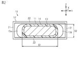
- FIG. 1 is a perspective view of the wire harness of the embodiment.
- FIG. 2 is a cross-sectional view of a wire harness of the same form.
- FIG. 3 is a plan view of the wire harness of the same form.
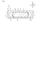
- FIG. 4 is a cross-sectional view of the wire harness of the modified example.
- the wire harness of the present disclosure is [1] A wire harness comprising a flat electric wire having a thickness smaller than a width dimension and a tubular exterior member surrounding the outer periphery of the electric wire.
- the exterior member has a bent portion that is bent so that a part of the electric wire in the length direction protrudes in the width direction.
- the bent portion of the electric wire bends during tolerance absorption, the bent portion can be deformed so as to spread outward in the width direction of the electric wire. That is, by providing the bent portion in the electric wire, it is possible to make the electric wire less likely to bend in the thickness direction when absorbing the tolerance. Therefore, it is not necessary to set a clearance for absorbing the tolerance between the electric wire and the inner surface of the exterior member in the thickness direction of the electric wire (or the clearance can be set small even if it is set), so that the thickness of the electric wire can be set. It is possible to reduce the size of the exterior member in the longitudinal direction.
- the bent portion is formed so that the bent state of the bent portion is maintained even when the electric wire is removed from the exterior member. According to this configuration, a bent portion is formed (habited) on the electric wire in advance, and the electric wire having the bent portion can be assembled to the exterior member. As a result, it is not necessary to form the bent portion (that is, to assemble the electric wire to the exterior member while bending the electric wire) when assembling the electric wire to the exterior member, which can contribute to the improvement of the assembling property of the electric wire.
- a plurality of the bent portions are provided along the length direction of the electric wire. According to this configuration, it is possible to widen the range corresponding to the tolerance, that is, the tolerance absorption capacity by the bending of the plurality of bent portions provided along the length direction of the electric wire.
- the exterior member has a pair of first side wall portions facing each other in the width direction, and at least one of the pair of first side wall portions is separated from the bent portion in the width direction. According to this configuration, when the tolerance is absorbed, the bent portion of the electric wire can be suitably bent in the width direction inside the exterior member.
- the exterior member has a pair of second side wall portions facing each other in the thickness direction, and each of the pair of second side wall portions is in contact with the bent portion in the thickness direction. According to this configuration, the size of the exterior member in the thickness direction of the electric wire can be further reduced.
- the exterior member includes a first member having one of the pair of second side wall portions and a second member having the other of the pair of second side wall portions as separate parts. According to this configuration, it is possible to easily assemble the electric wire inside the exterior member while adopting a configuration in which the pair of second side wall portions of the exterior member are in contact with the bent portion of the electric wire.
- the X-axis in the XYZ axes orthogonal to each other in the drawing represents the length direction X of the electric wire 11
- the Y-axis represents the width direction Y of the electric wire 11
- the Z-axis represents the thickness direction Z of the electric wire 11.
- the wire harness 10 shown in FIG. 1 is a wire harness used for electrical connection in a battery module (not shown) such as a hybrid vehicle or an electric vehicle.
- the wire harness 10 includes an electric wire 11 and a cylindrical exterior member 12 that surrounds the outer periphery of the electric wire 11 in a part or the whole of the length direction X of the electric wire 11.
- the exterior member 12 has a long cylindrical shape as a whole. An electric wire 11 is inserted in the internal space of the exterior member 12.
- the "cylindrical shape" in the present specification may be regarded as a cylindrical shape as a whole, and has a tubular shape by combining a plurality of parts, a notch in a part like a C shape, and the like. Including things.
- the exterior member 12 of the present embodiment is composed of one component.
- the cross-sectional shape (that is, the cross-sectional shape) orthogonal to the length direction of the exterior member 12 is, for example, a substantially rectangular shape.
- the exterior member 12 is configured as, for example, a shield protector for preventing electromagnetic noise emitted from the electric wire 11 from leaking to the outside.
- the exterior member 12 as a shield protector is formed of a conductor such as metal.
- a metal material such as copper or aluminum can be used as the material for forming the shield protector.
- the electric wire 11 has a core wire 13 and an insulating coating 14 that covers the outer periphery of the core wire 13.
- the core wire 13 is made of, for example, a plurality of strands made of conductors and has flexibility.
- a stranded wire formed by twisting a plurality of strands can be used.
- a material for forming the plurality of strands of the core wire 13 for example, a metal material such as copper-based or aluminum-based can be used.
- the insulating coating 14 that covers the outer peripheral surface of the core wire 13 is intended to electrically insulate the core wire 13 from the outside in substantially the entire length direction X.
- the insulating coating 14 is formed of, for example, a synthetic resin material.
- connection terminals are fixed to each exposed portion of the core wire 13. Then, each connection terminal at both ends of the electric wire 11 in the length direction X is connected to a mating component (not shown).
- the electric wire 11 has a flat shape in which the dimension D2 in the thickness direction Z is smaller than the dimension D1 in the width direction Y over the entire length in the length direction X.
- the cross-sectional shape (that is, the cross-sectional shape) orthogonal to the length direction X of the electric wire 11 can be any shape such as a polygonal shape, a semicircular shape, and an elliptical shape.
- the cross-sectional shape of the electric wire 11 of the present embodiment is substantially rectangular.
- the electric wire 11 has a plurality of bent portions 15a and 15b bent so that a part of the length direction X of the electric wire 11 protrudes in the width direction Y. ..
- the first bent portion 15a has, for example, a curved shape protruding to one side in the width direction Y.
- the second bent portion 15b has, for example, a curved shape protruding to the other side in the width direction Y.
- the first bent portion 15a and the second bent portion 15b are arranged side by side in the length direction X of the electric wire 11.
- the first bent portion 15a and the second bent portion 15b are connected in the length direction X of the electric wire 11, so that the range in which the bent portions 15a and 15b of the electric wire 11 are formed is wavy in the thickness direction Z. Is doing.
- the range in which the bent portions 15a and 15b of the electric wire 11 are formed is set to, for example, a part of the length direction X of the electric wire 11.
- the length of the range in which the bent portions 15a and 15b of the electric wire 11 are formed is set according to the positional tolerance of the mating component connected to both ends of the electric wire 11.
- first bent portion 15a and the second bent portion 15b are not bent in the thickness direction Z. That is, both side surfaces of the electric wire 11 in the thickness direction Z are substantially flat and parallel to each other, and the shape of the electric wire 11 in the width direction Y is substantially linear.
- the insulating coating 14 is extruded at the same time as the core wire 13 in which a plurality of strands are twisted is formed. At this time, the electric wire 11 has a linear shape when viewed from the thickness direction Z.
- the bent portions 15a and 15b having the above-mentioned shape are formed on the linear electric wire 11 by using a roller or the like (not shown) while heating.
- the bent shapes of the bent portions 15a and 15b are habituated.
- the bent states of the bent portions 15a and 15b are maintained even when the electric wire 11 is not arranged inside the exterior member 12 (the electric wire 11 is removed from the exterior member 12). ..
- the electric wire 11 on which the bent portions 15a and 15b are formed is assembled to the exterior member 12.
- the electric wire 11 is inserted into the exterior member 12 along the length direction X.
- the exterior member 12 includes a pair of first side wall portions 21 facing each other in the width direction Y of the electric wire 11 and a pair of second side wall portions 22 facing each other in the thickness direction Z of the electric wire 11. have.
- An annular peripheral wall of the exterior member 12 is formed from each of the first side wall portions 21 and each of the second side wall portions 22, and the electric wire 11 is inserted inside the peripheral wall.
- FIG. 2 shows a state in which each first side wall portion 21 is separated from each of the bent portions 15a and 15b.
- FIG. 2 shows a state in which one second side wall portion 22 is in contact with the bent portions 15a and 15b, and the other second side wall portion 22 is separated from the bent portions 15a and 15b.
- the distance between the mating parts may be shorter than the reference length within the tolerance range.
- the bent portions 15a and 15b in the exterior member 12 are bent so as to increase the amount of protrusion to the outside in the width direction Y, so that the position of the mating part is located. Tolerances can be absorbed. At this time, for example, the bent portions 15a and 15b come into contact with the pair of first side wall portions 21, respectively.
- the bent portions 15a and 15b are deformed so that the amount of protrusion to the outside in the width direction Y is reduced (the electric wire 11 is linear). By deforming it so that it approaches, it is possible to absorb the positional tolerance of the mating part.
- the deformation of the bent portions 15a and 15b in the width direction Y makes it possible to absorb not only the positional tolerance of the mating part but also the misalignment caused by the mating part due to thermal expansion. Further, when the length of the electric wire 11 is adjusted to the maximum value of the positional tolerance of the mating parts (the maximum tolerance of the distance between the mating parts), the bent portions 15a and 15b are deformed in the width direction Y at the time of absorbing the tolerance. Can be limited to the outside of the width direction Y only.
- the bent portions 15a and 15b at the time of absorbing the tolerance are in the width direction Y.
- the deformation can be limited to the inside of the width direction Y only.
- the bent portions 15a and 15b are in contact with each of the first side wall portions 21 of the exterior member 12 before the electric wire 11 is connected to the mating component.
- the electric wire 11 has bent portions 15a and 15b inside the exterior member 12 so that a part of the electric wire 11 in the length direction X protrudes in the width direction Y.
- the bent portions 15a and 15b of the electric wire 11 can be bent so as to spread outward in the width direction Y. That is, by providing the bent portions 15a and 15b on the electric wire 11, it is possible to make the electric wire 11 less likely to bend in the thickness direction Z when absorbing the tolerance. Therefore, it is not necessary to set a clearance for absorbing the tolerance between the electric wire 11 and the inner surface of the exterior member 12 in the thickness direction Z of the electric wire 11 (or the clearance can be set small even if it is set). , The dimension of the exterior member 12 in the thickness direction Z of the electric wire 11 can be reduced.
- the air layer between the electric wire 11 and the exterior member 12 in the thickness direction Z can be eliminated or made extremely small, the heat generated by the electric wire 11 can be easily released to the outside of the exterior member 12. It becomes. As a result, it is possible to contribute to the miniaturization of the size of the electric wire 11.
- bent portions 15a and 15b are formed so that the bent states of the bent portions 15a and 15b are maintained even when the electric wire 11 is removed from the exterior member 12. According to this configuration, the bent portions 15a and 15b are formed (habited) in advance on the electric wire 11, and the electric wire 11 having the bent portions 15a and 15b can be assembled to the exterior member 12. As a result, it is not necessary to form the bent portions 15a and 15b (that is, to assemble the electric wire 11 to the exterior member 12 while bending the electric wire 11) when assembling the electric wire 11 to the exterior member 12, so that the assembling property of the electric wire 11 is improved. Can contribute.
- a plurality of bent portions 15a and 15b are provided along the length direction X of the electric wire 11. According to this configuration, the range corresponding to the tolerance, that is, the tolerance absorbing capacity can be expanded by the bending of the plurality of bent portions 15a and 15b provided along the length direction X of the electric wire 11.
- the exterior member 12 has a pair of first side wall portions 21 facing each other in the width direction Y. At least one of the pair of first side wall portions 21 is separated from the bent portions 15a and 15b in the width direction Y. According to this configuration, when the tolerance is absorbed, the bent portions 15a and 15b of the electric wire 11 can be suitably bent in the width direction Y inside the exterior member 12.
- the exterior member 12 has a pair of second side wall portions 22 facing each other in the thickness direction Z. At least one of the pair of second side wall portions 22 is separated from the bent portions 15a and 15b of the electric wire 11 in the thickness direction Z. According to this configuration, a clearance is generated between the electric wire 11 and the exterior member 12 in the thickness direction Z. Therefore, for example, the workability when the electric wire 11 is inserted into the exterior member 12 along the length direction X can be improved.
- the electric wire 11 has a core wire 13 composed of a stranded wire in which a plurality of strands are twisted together. According to this configuration, it is easy to improve the flexibility of the core wire 13 as compared with the case where the core wire 13 is composed of a single core wire, a bus bar, or the like. Therefore, the bent portions 15a and 15b of the electric wire 11 can be easily bent in the width direction Y, and as a result, the bending of the bent portions 15a and 15b in the width direction Y can appropriately absorb the position tolerance and the like. It will be possible.
- each of the pair of second side wall portions 22 may be configured to come into contact with the bent portions 15a and 15b in the thickness direction Z. According to this configuration, the dimension of the exterior member 12 in the thickness direction Z of the electric wire 11 can be further reduced.
- the exterior member 12 is composed of one component, but the present invention is not limited to this, and for example, as shown in FIG. 4, there are two parts, a case body 31 as the first member and a lid 32 as the second member.
- the exterior member 12 may be composed of parts.
- the case body 31 has one of a pair of second side wall portions 22 (lower second side wall portion 22 in FIG. 4) and a pair of first side wall portions 21.
- the lid 32 has the other of the pair of second side wall portions 22 (upper second side wall portion 22 in FIG. 4).
- the bent portions 15a and 15b of the electric wire 11 are sandwiched in the thickness direction Z by the second side wall portion 22 of the case body 31 and the second side wall portion 22 of the lid 32. That is, each of the second side wall portion 22 of the case body 31 and the second side wall portion 22 of the lid 32 are in contact with the bent portions 15a and 15b in the thickness direction Z. As a result, the dimension of the exterior member 12 in the thickness direction Z of the electric wire 11 can be further reduced.
- the electric wire 11 when assembling the electric wire 11 to the exterior member 12, first, the electric wire 11 is arranged between the pair of first side wall portions 21 in the case main body 31. At this time, since the pair of first side wall portions 21 of the case body 31 are open in the thickness direction Z, it is possible to insert the electric wire 11 between the pair of first side wall portions 21 in the thickness direction Z. It has become.
- the lid 32 is assembled to the case body 31 on which the electric wire 11 is arranged.
- a fixing structure of the lid 32 to the case body 31 for example, a locking structure using a general lock piece can be used.
- the exterior member 12 includes a case main body 31 having a second side wall portion 22 and a lid body 32 as separate parts. According to this configuration, the electric wire 11 is easily assembled inside the exterior member 12 while adopting a configuration in which the pair of second side wall portions 22 are in contact with the bent portions 15a and 15b of the electric wire 11 in the thickness direction Z, respectively. It becomes possible.
- the case main body 31 and the lid body 32 each have a first side wall portion 21 (the boundary portion between the case main body 31 and the lid body 32 is the thickness direction Z of each first side wall portion 21). It may be changed to the configuration set in the middle part of.
- the cross-sectional shape of the exterior member 12 is not limited to a substantially rectangular shape, and may be any shape such as a cylindrical shape, an elliptical cylinder shape, or a polygonal cylinder shape.
- the exterior member 12 may be formed of a resin material.
- a synthetic resin such as polyolefin, polyamide, polyester, or ABS resin can be used.
- a corrugated tube made of synthetic resin or the like and having flexibility may be used as the exterior member 12.
- the configuration such as the shape of the bent portions 15a and 15b is not limited to the above embodiment, and can be changed as appropriate.
- the electric wire 11 includes a plurality of bent portions 15a and 15b, but the present invention is not limited to this, and the electric wire 11 may be configured to include one bent portion 15a (or one bent portion 15b). Further, for example, the bent portions 15a and 15b can be changed to a shape that bends like a crank.
- the first bent portion 15a and the second bent portion 15b may be provided alternately in the length direction X over the entire length of the electric wire 11 in the length direction X.
- the configuration in which the bent portions 15a and 15b are provided over the entire length of the electric wire 11 is suitable for forming the bent portions 15a and 15b at the time of manufacturing the electric wire 11.
- the manufacturing mode of the electric wire 11 is not limited to the above embodiment, and for example, the bent portions 15a and 15b may be habituated at the same time as the core wire 13 and the insulating coating 14 are formed.
- the application is applied to the wire harness 10 used for the electrical connection of the battery module, but the present invention is not limited to this, and the application may be applied to the wire harness used for the electrical connection of an in-vehicle device other than the battery module.
- the wire harness 10 alone may have at least one bent portion 15a and / or 15b, for example, before connecting the mating parts to both ends of the electric wire 11.
- At least one bent portion 15a and / or 15b of the electric wire 11 may be covered with the exterior member 12 by the wire harness 10 alone, for example, before connecting the mating parts to both ends of the electric wire 11.
- the bent portions 15a and / or 15b of the electric wire 11 are bent with a predetermined curvature (also referred to as a reference curvature or a pre-connection curvature) with the wire harness 10 alone, for example, before connecting the mating parts to both ends of the electric wire 11. May be done.
- the plurality of bent portions 15a and 15b may have the same curvature.
- the bent portions 15a and / or 15b of the electric wire 11 may have a curvature different from the reference curvature (also referred to as a post connection curvature).
- the difference between the post-connection curvature of the bent portion 15a and / or 15b and the pre-connection curvature of the bent portion 15a and / or 15b is generally the distance between the mating parts connected to both ends of the electric wire 11 and the reference length. Corresponds to the difference with.
- the amount of protrusion of the bent portions 15a and 15b in the width direction Y may be larger.
- the length of the electric wire 11 in the length direction X may be the shortest in a state where the bent portions 15a and 15b and the pair of first side wall portions 21 of the exterior member 12 are in contact with each other.
- the length of the electric wire 11 in the length direction X is the shortest, at least the length portion of the electric wire 11 housed inside the exterior member 12 may be curved, and has no linear length portion. It may be.
- the amount of protrusion of the bent portions 15a and 15b in the width direction Y may be smaller.
- at least the length of the electric wire 11 housed inside the exterior member 12 may be the longest in the length direction X.
- the electric wire 11 may be linear.
- each of the plurality of bent portions 15a and 15b of the electric wire 11 of the embodiment may be referred to as an in-plane bent portion having a pair of opposing eccentric planes and a pair of opposing curved side surfaces.
- the pair of opposing curved side surfaces of each of the plurality of bent portions 15a and 15b may be a pair of a convex curved side surface and a concave curved side surface.
- the concave side surfaces of the bent portions 15a and 15b of the electric wire 11 may be non-contact with the inner surface of the exterior member 12.
- the bent portions 15a and 15b have a first bent portion 15a and a second bent portion 15b, and the first bent portions 15a are a pair of first bent portions in a state where both ends of the electric wire 11 are not connected to a connection partner.
- the second bent portion 15b may be formed so as to be in contact with one of the side wall portions 21 and to be in contact with the other of the pair of first side wall portions 21.
- the first bent portion 15a may have a curved shape protruding to one side in the width direction Y
- the second bent portion 15b may have a curved shape protruding to the other side in the width direction Y.
- the electric wire 11 may be a flat electric wire having a flat upper surface, a flat lower surface, and at least one bent portion 15a and / or 15b.
- the flat upper surface and the flat lower surface of the electric wire 11 are sometimes referred to as a pair of eccentric planes of the electric wire 11.
- at least one bent portion 15a and / or 15b is such that when the flat electric wire receives an external force in the length direction (for example, an extension force or a shortening force), the flat electric wire has a flat surface thereof.
- a wire bending directioning means configured to direct the bending direction of the flat electric wire so as to bend in the in-plane direction of (upper surface and / or lower surface).
- the first bent portion 15a and the second bent portion 15b are curved on both sides in the width direction Y by the same length from the center in the width direction Y of the electric wire 11. It is formed.
- the dimension of the electric wire 11 in the width direction Y may be constant over the entire length of the electric wire 11, for example, as in this example, or is constant over the length portion of the electric wire 11 corresponding to the overall length of the exterior member 12. There may be.
- Wire harness 11 Electric wire 12 Exterior member 13 Core wire 14 Insulation coating 15a First bent part (bent part) 15b Second bent part (bent part) 21 1st side wall 22 2nd side wall 31 Case body (1st member) 32 Lid (second member) D1 Width direction of the electric wire D2 Dimension in the thickness direction of the electric wire X Length direction of the electric wire Y Width direction of the electric wire Z Thickness direction of the electric wire
Landscapes
- Engineering & Computer Science (AREA)
- Architecture (AREA)
- Civil Engineering (AREA)
- Structural Engineering (AREA)
- Details Of Indoor Wiring (AREA)
- Insulated Conductors (AREA)
Abstract
本開示の一態様は、幅方向の寸法に対して厚さ方向の寸法が小さな扁平形状をなす電線と外装部材とを備えたワイヤハーネスに関し、電線の厚さ方向における外装部材の小型化を可能にする。ワイヤハーネス(10)は、幅方向(Y)の寸法に対して厚さ方向(Z)の寸法が小さな扁平形状をなす電線(11)と、電線(11)の外周を包囲する筒状の外装部材(12)とを備える。そして、電線(11)は、電線(11)の長さ方向(X)の一部が幅方向(Y)に突出するように屈曲された屈曲部(15a,15b)を、外装部材(12)の内部に有している。
Description
本開示は、ワイヤハーネスに関するものである。
例えば、特許文献1に記載された車両用のワイヤハーネスは、一対の相手部品同士を電気的に接続する電線と、その電線の外周を包囲する筒状の外装部材とを備えている。電線には、撚り線などの可撓性を有する線が用いられる。また、電線と外装部材の内側面との間にはクリアランスが設定されており、外装部材の内部で電線が撓むことが許容されている。同ワイヤハーネスでは、電線の長さを、一対の相手部品の位置公差が最大となる場合でも対応できる長さに設定する。そして、外装部材の内部で電線を撓ませることで、相手部品の位置公差を吸収するようになっている。
また、例えば、特許文献2には、幅方向の寸法に対して厚さ方向の寸法が小さな扁平形状をなす電線(扁平電線)を用いたワイヤハーネスが開示されている。
上記特許文献1のようなワイヤハーネスでは、電線と外装部材の内側面との間に、公差吸収のためのクリアランスを設定する必要があるため、外装部材を小型化する点において改善の余地があった。
そこで、特許文献2に記載されるような扁平電線を採用すれば、電線の厚さを薄くした分、外装部材を電線の厚さ方向に小型化することは可能である。しかしながら、外装部材の内部で扁平電線が撓んで位置公差を吸収するとき、扁平電線はその扁平形状によって厚さ方向に変形しやすい。このため、扁平電線の厚さ方向において扁平電線と外装部材との間に公差吸収のための十分なクリアランスを設定する必要があるため、扁平電線の厚さ方向に外装部材を小型化する点において、なお改善の余地があった。
そこで、幅方向の寸法に対して厚さ方向の寸法が小さな扁平形状をなす電線を備えたワイヤハーネスにおいて、電線の厚さ方向における外装部材の小型化を可能にすることを目的とする。
本開示のワイヤハーネスは、幅方向の寸法に対して厚さ方向の寸法が小さな扁平形状をなす電線と、前記電線の外周を包囲する筒状の外装部材と、を備えたワイヤハーネスであって、前記電線は、前記電線の長さ方向の一部が前記幅方向に突出するように屈曲された屈曲部を、前記外装部材の内部に有している。
本開示によれば、幅方向の寸法に対して厚さ方向の寸法が小さな扁平形状をなす電線を備えたワイヤハーネスにおいて、電線の厚さ方向における外装部材の小型化が可能となる。
[本開示の実施形態の説明]
最初に本開示の実施態様を列記して説明する。
本開示のワイヤハーネスは、
[1]幅方向の寸法に対して厚さ方向の寸法が小さな扁平形状をなす電線と、前記電線の外周を包囲する筒状の外装部材と、を備えたワイヤハーネスであって、前記電線は、前記電線の長さ方向の一部が前記幅方向に突出するように屈曲された屈曲部を、前記外装部材の内部に有している。
最初に本開示の実施態様を列記して説明する。
本開示のワイヤハーネスは、
[1]幅方向の寸法に対して厚さ方向の寸法が小さな扁平形状をなす電線と、前記電線の外周を包囲する筒状の外装部材と、を備えたワイヤハーネスであって、前記電線は、前記電線の長さ方向の一部が前記幅方向に突出するように屈曲された屈曲部を、前記外装部材の内部に有している。
この構成によれば、公差吸収時に電線の屈曲部が撓むとき、屈曲部を電線の幅方向の外側に広がるように変形させることができる。すなわち、電線に上記屈曲部を設けることで、公差吸収時に電線を厚さ方向に撓みにくくすることができる。従って、電線の厚さ方向における電線と外装部材の内側面との間に、公差吸収のためのクリアランスを設定する必要がなくなる(あるいは、クリアランスを設定するにせよ小さく設定できる)ため、電線の厚さ方向における外装部材の寸法を小さくすることが可能となる。
[2]前記屈曲部は、前記電線を前記外装部材から取り外した状態においても前記屈曲部の屈曲状態が保たれるように形成されている。
この構成によれば、予め電線に屈曲部を成形(癖付け)しておき、屈曲部を有する電線を外装部材に組み付けることが可能となる。これにより、外装部材への電線の組付時に屈曲部を成形する(すなわち、電線を曲げつつ外装部材に組み付ける)必要がなくなるため、電線の組付性の向上に寄与できる。
この構成によれば、予め電線に屈曲部を成形(癖付け)しておき、屈曲部を有する電線を外装部材に組み付けることが可能となる。これにより、外装部材への電線の組付時に屈曲部を成形する(すなわち、電線を曲げつつ外装部材に組み付ける)必要がなくなるため、電線の組付性の向上に寄与できる。
[3]前記屈曲部は、前記電線の長さ方向に沿って複数設けられている。
この構成によれば、電線の長さ方向に沿って設けられた複数の屈曲部の撓みによって、公差に対する対応範囲、すなわち公差吸収能力を広げることが可能となる。
この構成によれば、電線の長さ方向に沿って設けられた複数の屈曲部の撓みによって、公差に対する対応範囲、すなわち公差吸収能力を広げることが可能となる。
[4]前記外装部材は、前記幅方向において互いに対向する一対の第1側壁部を有し、前記一対の第1側壁部の少なくとも一方は、前記幅方向において前記屈曲部から離間している。この構成によれば、公差吸収時において、外装部材の内部で電線の屈曲部を幅方向に好適に撓ませることが可能となる。
[5]前記外装部材は、前記厚さ方向において互いに対向する一対の第2側壁部を有し、前記一対の第2側壁部の各々が前記厚さ方向において前記屈曲部に接触している。
この構成によれば、電線の厚さ方向における外装部材の寸法を、更に小さくすることが可能となる。
この構成によれば、電線の厚さ方向における外装部材の寸法を、更に小さくすることが可能となる。
[6]前記外装部材は、前記一対の第2側壁部の一方を有する第1部材と、前記一対の第2側壁部の他方を有する第2部材とを、それぞれ別部品として備えている。
この構成によれば、外装部材における一対の第2側壁部がそれぞれ電線の屈曲部に接触する構成を採用しつつも、電線を外装部材の内部に容易に組み付けることが可能となる。
この構成によれば、外装部材における一対の第2側壁部がそれぞれ電線の屈曲部に接触する構成を採用しつつも、電線を外装部材の内部に容易に組み付けることが可能となる。
[本開示の実施形態の詳細]
本開示のワイヤハーネスの具体例を、以下に図面を参照しつつ説明する。各図面では、説明の便宜上、構成の一部を誇張または簡略化して示す場合がある。また、各部分の寸法比率については各図面で異なる場合がある。また、本明細書における「平行」や「直交」は、厳密に平行や直交の場合のみでなく、本実施形態における作用ならびに効果を奏する範囲内で概ね平行や概ね直交の場合も含まれる。なお、本発明はこれらの例示に限定されるものではなく、特許請求の範囲によって示され、特許請求の範囲と均等の意味および範囲内でのすべての変更が含まれることが意図される。また、図面中の互いに直交するXYZ軸におけるX軸は、電線11の長さ方向Xを表し、Y軸は電線11の幅方向Yを表し、Z軸は電線11の厚さ方向Zを表している。
本開示のワイヤハーネスの具体例を、以下に図面を参照しつつ説明する。各図面では、説明の便宜上、構成の一部を誇張または簡略化して示す場合がある。また、各部分の寸法比率については各図面で異なる場合がある。また、本明細書における「平行」や「直交」は、厳密に平行や直交の場合のみでなく、本実施形態における作用ならびに効果を奏する範囲内で概ね平行や概ね直交の場合も含まれる。なお、本発明はこれらの例示に限定されるものではなく、特許請求の範囲によって示され、特許請求の範囲と均等の意味および範囲内でのすべての変更が含まれることが意図される。また、図面中の互いに直交するXYZ軸におけるX軸は、電線11の長さ方向Xを表し、Y軸は電線11の幅方向Yを表し、Z軸は電線11の厚さ方向Zを表している。
図1に示すワイヤハーネス10は、例えば、ハイブリッド車や電気自動車などの図示しない電池モジュールにおける電気接続に用いられるワイヤハーネスである。
ワイヤハーネス10は、電線11と、電線11の長さ方向Xの一部または全体において電線11の外周を包囲する筒状の外装部材12と、を備えている。
ワイヤハーネス10は、電線11と、電線11の長さ方向Xの一部または全体において電線11の外周を包囲する筒状の外装部材12と、を備えている。
(外装部材12)
外装部材12は、全体として長尺の筒状をなしている。外装部材12の内部空間には電線11が挿通されている。なお、本明細書における「筒状」は、全体として筒状と見做せればよく、複数の部品を組み合わせて筒状をなすものや、C字状のように一部に切り欠きなどを有するものも含む。また、本実施形態の外装部材12は一部品で構成されている。また、外装部材12の長さ方向に直交する断面形状(つまり、横断面形状)は、例えば、略長方形状をなしている。
外装部材12は、全体として長尺の筒状をなしている。外装部材12の内部空間には電線11が挿通されている。なお、本明細書における「筒状」は、全体として筒状と見做せればよく、複数の部品を組み合わせて筒状をなすものや、C字状のように一部に切り欠きなどを有するものも含む。また、本実施形態の外装部材12は一部品で構成されている。また、外装部材12の長さ方向に直交する断面形状(つまり、横断面形状)は、例えば、略長方形状をなしている。
外装部材12は、例えば、電線11から発せられる電磁ノイズを外部に漏らさないためのシールドプロテクタとして構成されている。シールドプロテクタとしての外装部材12は、例えば金属などの導体にて形成されている。なお、シールドプロテクタの形成材料としては、銅系やアルミニウム系などの金属材料を用いることができる。
(電線11)
電線11は、芯線13と、芯線13の外周を被覆する絶縁被覆14とを有している。
芯線13は、例えば、導体からなる複数の素線にて構成され、可撓性を有している。芯線13としては、例えば、複数の素線が撚り合わされてなる撚り線を用いることができる。芯線13の複数の素線の形成材料としては、例えば、銅系やアルミニウム系などの金属材料を用いることができる。
電線11は、芯線13と、芯線13の外周を被覆する絶縁被覆14とを有している。
芯線13は、例えば、導体からなる複数の素線にて構成され、可撓性を有している。芯線13としては、例えば、複数の素線が撚り合わされてなる撚り線を用いることができる。芯線13の複数の素線の形成材料としては、例えば、銅系やアルミニウム系などの金属材料を用いることができる。
芯線13の外周面を被覆する絶縁被覆14は、長さ方向Xの略全体において、芯線13と外部との電気的な絶縁を図るものである。絶縁被覆14は、例えば、合成樹脂材から形成されている。
電線11の長さ方向Xの両端部では、芯線13が絶縁被覆14から露出されており、それら芯線13の各露出部分には、図示しない接続端子が固定されている。そして、電線11の長さ方向Xの両端部の各接続端子は、図示しない相手部品に接続されるようになっている。
図1及び図2に示すように、電線11は、長さ方向Xの全長に亘り、幅方向Yの寸法D1に対して厚さ方向Zの寸法D2が小さな扁平形状をなしている。電線11の長さ方向Xに直交する断面形状(つまり、横断面形状)は、多角形状、半円状、楕円状など、任意の形状にすることができる。本実施形態の電線11の横断面形状は、略長方形状をなしている。
(屈曲部15a,15b)
図1及び図3に示すように、電線11は、例えば、電線11の長さ方向Xの一部が幅方向Yに突出するように屈曲された複数の屈曲部15a,15bを有している。第1の屈曲部15aは、例えば、幅方向Yの一方側に突出する湾曲形状をなしている。第2の屈曲部15bは、例えば、幅方向Yの他方側に突出する湾曲形状をなしている。第1の屈曲部15aと第2の屈曲部15bとは、電線11の長さ方向Xに並設されている。そして、第1の屈曲部15a及び第2の屈曲部15bが電線11の長さ方向Xに連なることで、電線11における屈曲部15a,15bが形成された範囲は、厚さ方向Z視で波状をなしている。なお、電線11における屈曲部15a,15bが形成された範囲は、例えば、電線11の長さ方向Xの一部に設定されている。なお、電線11における屈曲部15a,15bを形成する範囲の長さは、電線11の両端部に接続される前記相手部品の位置公差などに応じて設定される。
図1及び図3に示すように、電線11は、例えば、電線11の長さ方向Xの一部が幅方向Yに突出するように屈曲された複数の屈曲部15a,15bを有している。第1の屈曲部15aは、例えば、幅方向Yの一方側に突出する湾曲形状をなしている。第2の屈曲部15bは、例えば、幅方向Yの他方側に突出する湾曲形状をなしている。第1の屈曲部15aと第2の屈曲部15bとは、電線11の長さ方向Xに並設されている。そして、第1の屈曲部15a及び第2の屈曲部15bが電線11の長さ方向Xに連なることで、電線11における屈曲部15a,15bが形成された範囲は、厚さ方向Z視で波状をなしている。なお、電線11における屈曲部15a,15bが形成された範囲は、例えば、電線11の長さ方向Xの一部に設定されている。なお、電線11における屈曲部15a,15bを形成する範囲の長さは、電線11の両端部に接続される前記相手部品の位置公差などに応じて設定される。
また、第1の屈曲部15a及び第2の屈曲部15bは、厚さ方向Zには屈曲していない。すなわち、電線11の厚さ方向Zの両側面は互いに平行な略平面状をなし、電線11の幅方向Y視の形状は略直線状をなしている。
電線11の製造態様の一例としては、まず、複数の素線を撚り合わせる芯線13の成形と同時に、絶縁被覆14を押出成形する。このとき、電線11は、厚さ方向Zから見て直線状をなす。
次に、直線状の電線11に対して、加熱しながら図示しないローラーなどを用いて上記の形状の屈曲部15a,15bを成形する。このように、加熱しながら屈曲部15a,15bを成形することで、屈曲部15a,15bの屈曲形状が癖付けされる。これにより、電線11が外装部材12の内部に配置されていない状態(電線11が外装部材12から取り外された状態)においても、屈曲部15a,15bの屈曲状態が保たれるようになっている。
その後、屈曲部15a,15bが形成された電線11を、外装部材12に組み付ける。本実施形態では、電線11を外装部材12に組み付ける際、電線11を長さ方向Xに沿って外装部材12に挿入するようになっている。
図2に示すように、外装部材12は、電線11の幅方向Yに互いに対向する一対の第1側壁部21と、電線11の厚さ方向Zに互いに対向する一対の第2側壁部22とを有している。そして、各第1側壁部21と各第2側壁部22とから、外装部材12の環状の周壁が形成されており、当該周壁の内側に電線11が挿通されている。
電線11が外装部材12に挿通された状態において、一対の第1側壁部21の少なくとも一方は、電線11の各屈曲部15a,15bから幅方向Yに離間している。図2では、各第1側壁部21が、各屈曲部15a,15bから離間された状態を示している。
また、一対の第2側壁部22の少なくとも一方は、電線11の各屈曲部15a,15bから厚さ方向Zに離間している。図2では、一方の第2側壁部22が各屈曲部15a,15bに接触し、他方の第2側壁部22が各屈曲部15a,15bから離間された状態を示している。
上記のような構成によれば、電線11と外装部材12との間に、幅方向Y及び厚さ方向Zにおけるクリアランスが生じる。従って、電線11を長さ方向Xに沿って外装部材12に挿入する際の作業性を向上させることができる。
本実施形態の作用について説明する。
図3に示すように、電線11の長さ方向Xの両端部を各相手部品に接続する際、各相手部品同士の距離が公差範囲内で基準長さよりも短い場合がある。このとき、図3中の2点鎖線で示すように、外装部材12内の屈曲部15a,15bが、幅方向Yの外側への突出量が増えるように撓むことで、当該相手部品の位置公差を吸収することができる。このとき、例えば、屈曲部15a,15bは一対の第1側壁部21にそれぞれ当接する。
図3に示すように、電線11の長さ方向Xの両端部を各相手部品に接続する際、各相手部品同士の距離が公差範囲内で基準長さよりも短い場合がある。このとき、図3中の2点鎖線で示すように、外装部材12内の屈曲部15a,15bが、幅方向Yの外側への突出量が増えるように撓むことで、当該相手部品の位置公差を吸収することができる。このとき、例えば、屈曲部15a,15bは一対の第1側壁部21にそれぞれ当接する。
一方、各相手部品同士の距離が公差範囲内で基準長さよりも長い場合には、屈曲部15a,15bが、幅方向Yの外側への突出量が減るように変形(電線11が直線状に近づくように変形)することで、当該相手部品の位置公差を吸収することができる。
なお、屈曲部15a,15bの幅方向Yの変形によって、相手部品の位置公差だけでなく、熱膨張によって相手部品などで生じる位置ずれも吸収することが可能となっている。
また、電線11の長さを相手部品の位置公差の最大値(各相手部品同士の距離の最大公差)に合わせた場合には、公差吸収時の屈曲部15a,15bの幅方向Yへの変形を幅方向Yの外側のみに限定することができる。反対に、電線11の長さを相手部品の位置公差の最小値(各相手部品同士の距離の最小公差)に合わせた場合には、公差吸収時の屈曲部15a,15bの幅方向Yへの変形を幅方向Yの内側のみに限定することができる。この場合、電線11を相手部品に接続する前の時点で、屈曲部15a,15bが外装部材12の各第1側壁部21に接触する構成となる。
また、電線11の長さを相手部品の位置公差の最大値(各相手部品同士の距離の最大公差)に合わせた場合には、公差吸収時の屈曲部15a,15bの幅方向Yへの変形を幅方向Yの外側のみに限定することができる。反対に、電線11の長さを相手部品の位置公差の最小値(各相手部品同士の距離の最小公差)に合わせた場合には、公差吸収時の屈曲部15a,15bの幅方向Yへの変形を幅方向Yの内側のみに限定することができる。この場合、電線11を相手部品に接続する前の時点で、屈曲部15a,15bが外装部材12の各第1側壁部21に接触する構成となる。
本実施形態の効果について説明する。
(1)電線11は、電線11の長さ方向Xの一部が幅方向Yに突出するように屈曲された屈曲部15a,15bを、外装部材12の内部に有している。この構成によれば、公差吸収時において、電線11の屈曲部15a,15bを幅方向Yの外側に広がるように撓ませることができる。すなわち、電線11に屈曲部15a,15bを設けることで、公差吸収時に電線11を厚さ方向Zに撓みにくくすることができる。従って、電線11の厚さ方向Zにおける電線11と外装部材12の内側面との間に、公差吸収のためのクリアランスを設定する必要がなくなる(あるいは、クリアランスを設定するにせよ小さく設定できる)ため、電線11の厚さ方向Zにおける外装部材12の寸法を小さくすることが可能となる。
(1)電線11は、電線11の長さ方向Xの一部が幅方向Yに突出するように屈曲された屈曲部15a,15bを、外装部材12の内部に有している。この構成によれば、公差吸収時において、電線11の屈曲部15a,15bを幅方向Yの外側に広がるように撓ませることができる。すなわち、電線11に屈曲部15a,15bを設けることで、公差吸収時に電線11を厚さ方向Zに撓みにくくすることができる。従って、電線11の厚さ方向Zにおける電線11と外装部材12の内側面との間に、公差吸収のためのクリアランスを設定する必要がなくなる(あるいは、クリアランスを設定するにせよ小さく設定できる)ため、電線11の厚さ方向Zにおける外装部材12の寸法を小さくすることが可能となる。
また、厚さ方向Zにおける電線11と外装部材12との間の空気層を無くす、あるいは極めて小さくすることが可能となるため、電線11で生じた熱を外装部材12の外側に放出しやすい構成となる。その結果、電線11のサイズの小型化に寄与できる。
(2)屈曲部15a,15bは、電線11を外装部材12から取り外した状態においても屈曲部15a,15bの屈曲状態が保たれるように形成されている。この構成によれば、予め電線11に屈曲部15a,15bを成形(癖付け)しておき、屈曲部15a,15bを有する電線11を外装部材12に組み付けることが可能となる。これにより、外装部材12への電線11の組付時に屈曲部15a,15bを成形する(すなわち、電線11を曲げつつ外装部材12に組み付ける)必要がなくなるため、電線11の組付性の向上に寄与できる。
(3)屈曲部15a,15bは、電線11の長さ方向Xに沿って複数設けられている。この構成によれば、電線11の長さ方向Xに沿って設けられた複数の屈曲部15a,15bの撓みによって、公差に対する対応範囲、すなわち公差吸収能力を広げることが可能となる。
(4)外装部材12は、幅方向Yにおいて互いに対向する一対の第1側壁部21を有している。そして、一対の第1側壁部21の少なくとも一方は、幅方向Yにおいて屈曲部15a,15bから離間している。この構成によれば、公差吸収時において、外装部材12の内部で電線11の屈曲部15a,15bを幅方向Yに好適に撓ませることが可能となる。
(5)外装部材12は、厚さ方向Zにおいて互いに対向する一対の第2側壁部22を有している。そして、一対の第2側壁部22の少なくとも一方は、電線11の各屈曲部15a,15bから厚さ方向Zに離間している。この構成によれば、電線11と外装部材12との間に厚さ方向Zにおけるクリアランスが生じる。従って、例えば、電線11を長さ方向Xに沿って外装部材12に挿入する際の作業性を向上させることができる。
(6)電線11は、複数の素線が撚り合わされた撚り線からなる芯線13を有している。この構成によれば、芯線13を単芯線やバスバーなどで構成した場合と比べて、芯線13の可撓性を向上させやすい。このため、電線11の屈曲部15a,15bを幅方向Yに撓みやすくすることが可能となり、その結果、屈曲部15a,15bの幅方向Yの撓みによって、位置公差などを好適に吸収させることが可能となる。
本実施形態は、以下のように変更して実施することができる。本実施形態及び以下の変更例は、技術的に矛盾しない範囲で互いに組み合わせて実施することができる。
・上記実施形態のワイヤハーネス10において、一対の第2側壁部22の各々が厚さ方向Zにおいて屈曲部15a,15bに接触するように構成してもよい。この構成によれば、電線11の厚さ方向Zにおける外装部材12の寸法を、更に小さくすることが可能となる。
・上記実施形態のワイヤハーネス10において、一対の第2側壁部22の各々が厚さ方向Zにおいて屈曲部15a,15bに接触するように構成してもよい。この構成によれば、電線11の厚さ方向Zにおける外装部材12の寸法を、更に小さくすることが可能となる。
・上記実施形態では、外装部材12を一部品で構成したが、これに限らず、例えば図4に示すように、第1部材としてのケース本体31と第2部材としての蓋体32の2つの部品で外装部材12を構成してもよい。図4に示す例では、ケース本体31は、一対の第2側壁部22の一方(図4において下側の第2側壁部22)と、一対の第1側壁部21を有している。一方、蓋体32は、一対の第2側壁部22の他方(図4において上側の第2側壁部22)を有している。
そして、電線11の屈曲部15a,15bは、ケース本体31の第2側壁部22と、蓋体32の第2側壁部22とによって、厚さ方向Zに挟まれている。すなわち、ケース本体31の第2側壁部22及び蓋体32の第2側壁部22の各々は、厚さ方向Zにおいて屈曲部15a,15bに接触している。これにより、電線11の厚さ方向Zにおける外装部材12の寸法を、更に小さくすることが可能となる。
図4に示す例において、電線11を外装部材12に組み付ける際には、まず、ケース本体31における一対の第1側壁部21の間に電線11を配置する。このとき、ケース本体31の一対の第1側壁部21は厚さ方向Zに開放しているため、一対の第1側壁部21の間に電線11を厚さ方向Zに挿入することが可能となっている。
その後、電線11が配置されたケース本体31に、蓋体32を組み付ける。なお、ケース本体31に対する蓋体32の固定構造としては、例えば、一般的なロック片による係止構造を用いることができる。
上記のような構成では、外装部材12は、それぞれ第2側壁部22を備えるケース本体31と蓋体32とを別部品として備えている。この構成によれば、一対の第2側壁部22がそれぞれ電線11の屈曲部15a,15bに厚さ方向Zに接触する構成を採用しつつも、電線11を外装部材12の内部に容易に組み付けることが可能となる。
なお、図4に示す例において、ケース本体31の第2側壁部22及び蓋体32の第2側壁部22の少なくとも一方が、電線11の各屈曲部15a,15bから厚さ方向Zに離間するように構成してもよい。また、図4に示す例において、ケース本体31及び蓋体32がそれぞれ各第1側壁部21を有する構成(ケース本体31と蓋体32の境界部が各第1側壁部21の厚さ方向Zの中間部に設定された構成)に変更してもよい。
・外装部材12の横断面形状は略長方形状に限定されるものではなく、例えば、円筒形状、楕円筒形状、多角筒形状など、任意の形状にすることができる。
・外装部材12を樹脂材料にて形成してもよい。なお、樹脂製の外装部材12の形成材料としては、例えば、ポリオレフィン、ポリアミド、ポリエステル、ABS樹脂などの合成樹脂を用いることができる。また、外装部材12として、合成樹脂などからなり可撓性を有するコルゲートチューブを用いてもよい。
・外装部材12を樹脂材料にて形成してもよい。なお、樹脂製の外装部材12の形成材料としては、例えば、ポリオレフィン、ポリアミド、ポリエステル、ABS樹脂などの合成樹脂を用いることができる。また、外装部材12として、合成樹脂などからなり可撓性を有するコルゲートチューブを用いてもよい。
・屈曲部15a,15bの形状などの構成は、上記実施形態に限定されるものではなく、適宜変更可能である。例えば、上記実施形態では、電線11は複数の屈曲部15a,15bを備えるが、これに限らず、電線11が1つの屈曲部15a(または1つの屈曲部15b)を備える構成としてもよい。また、例えば、屈曲部15a,15bがクランク状に屈曲する形状に変更可能である。
・電線11の長さ方向Xの全長に亘り、第1の屈曲部15a及び第2の屈曲部15bを長さ方向Xに交互に設けてもよい。このように、電線11の全長に亘って屈曲部15a,15bを設ける構成は、電線11の製造時に屈曲部15a,15bを成形する場合に適している。
・電線11の製造態様は上記実施形態に限定されるものではなく、例えば、芯線13及び絶縁被覆14の成形と同時に屈曲部15a,15bの癖付けを行ってもよい。
・上記実施形態では、電池モジュールの電気接続に用いられるワイヤハーネス10に適用したが、これに限らず、電池モジュール以外の車載機器の電気接続に用いられるワイヤハーネスに適用してもよい。
・上記実施形態では、電池モジュールの電気接続に用いられるワイヤハーネス10に適用したが、これに限らず、電池モジュール以外の車載機器の電気接続に用いられるワイヤハーネスに適用してもよい。
・ワイヤハーネス10単独で、例えば電線11の両端部に相手部品を接続する前の状態で、電線11は少なくとも一つの屈曲部15aおよび/または15bを有してよい。ワイヤハーネス10単独で、例えば電線11の両端部に相手部品を接続する前の状態で、電線11の少なくとも一つの屈曲部15aおよび/または15bは外装部材12に覆われてよい。ワイヤハーネス10単独で、例えば電線11の両端部に相手部品を接続する前の状態で、電線11の屈曲部15aおよび/または15bは、所定の曲率(基準曲率またはプレ接続曲率ともいう)をもって屈曲されてよい。電線11が複数の屈曲部15a,15bを有する場合、複数の屈曲部15a,15bは同じ曲率を有してよい。例えば電線11の両端部に相手部品を接続した後の状態で、電線11の屈曲部15aおよび/または15bは、基準曲率とは異なる曲率(ポスト接続曲率ともいう)を有してよい。屈曲部15aおよび/または15bのポスト接続曲率と、当該屈曲部15aおよび/または15bのプレ接続曲率との差は、一般には、電線11の両端部に接続される相手部品同士の距離と基準長さとの差に対応する。
・例えば、電線11の両端部に接続される相手部品同士の距離が基準長さよりも短い場合には、屈曲部15a,15bの幅方向Yへの突出量はより大きくてよい。屈曲部15a,15bと外装部材12の一対の第1側壁部21とがそれぞれ当接する状態において、長さ方向Xにおける電線11の長さが最も短くなってもよい。長さ方向Xにおける電線11の長さが最も短い場合、少なくとも外装部材12の内部に収容された電線11の長さ部分は曲線状であってよく、直線的長さ部分を有しない非直線状であってもよい。
例えば、電線11の両端部に接続される相手部品同士の距離が基準長さよりも長い場合には、屈曲部15a,15bの幅方向Yへの突出量はより小さくてよい。屈曲部15a,15bと外装部材12の一対の第1側壁部21とが接触しない状態において、少なくとも外装部材12の内部に収容された電線11の長さが最も長くなってもよい長さ方向Xにおける電線11の長さが最も長い場合、電線11は直線状であってもよい。
例えば、電線11の両端部に接続される相手部品同士の距離が基準長さよりも長い場合には、屈曲部15a,15bの幅方向Yへの突出量はより小さくてよい。屈曲部15a,15bと外装部材12の一対の第1側壁部21とが接触しない状態において、少なくとも外装部材12の内部に収容された電線11の長さが最も長くなってもよい長さ方向Xにおける電線11の長さが最も長い場合、電線11は直線状であってもよい。
・実施形態の電線11の複数の屈曲部15a,15bの各々は、一対の対向する偏平面および一対の対向する湾曲側面を有する面内屈曲部と呼称することがある。複数の屈曲部15a,15bの各々の一対の対向する湾曲側面は、凸曲側面と凹曲側面との対であってよい。電線11の各屈曲部15a,15bの凹曲側面は、外装部材12の内面と非接触であってよい。
屈曲部15a,15bは、第1の屈曲部15a及び第2の屈曲部15bを有し、電線11の両端を接続相手に接続していない状態で、第1の屈曲部15aは一対の第1側壁部21のうちの一方に接触し、第2の屈曲部15bは一対の第1側壁部21のうちの他方に接触するように形成されてもよい。第1の屈曲部15aは、幅方向Yの一方側に突出する湾曲形状であり、第2の屈曲部15bは、幅方向Yの他方側に突出する湾曲形状であってもよい。
・図1に示すように、電線11は、平坦な上面と、平坦な下面と、少なくとも一つの屈曲部15aおよび/または15bとを有する扁平電線であってよい。電線11の平坦な上面と平坦な下面は、電線11の一対の偏平面と呼称することがある。電線11が扁平電線である場合、少なくとも一つの屈曲部15aおよび/または15bは、扁平電線が長さ方向の外力(例えば伸長力または短縮力)を受けたときに、当該扁平電線がその偏平面(上面および/または下面)の面内方向に撓むように、扁平電線の撓み方向を方向づけるように構成された、電線撓みの方向付け手段と呼称することがある。
・図2及び図3に示す例では、第1の屈曲部15a及び第2の屈曲部15bは、電線11の幅方向Yにおける中心から同じ長さ分だけ幅方向Yの両側に湾曲するように形成されている。電線11の幅方向Yにおける寸法は、この例のように例えば電線11の全長に亘って一定であってよく、または、外装部材12の全長に対応する電線11の長さ部分に亘って一定であってもよい。
10 ワイヤハーネス
11 電線
12 外装部材
13 芯線
14 絶縁被覆
15a 第1の屈曲部(屈曲部)
15b 第2の屈曲部(屈曲部)
21 第1側壁部
22 第2側壁部
31 ケース本体(第1部材)
32 蓋体(第2部材)
D1 電線の幅方向の寸法
D2 電線の厚さ方向の寸法
X 電線の長さ方向
Y 電線の幅方向
Z 電線の厚さ方向
11 電線
12 外装部材
13 芯線
14 絶縁被覆
15a 第1の屈曲部(屈曲部)
15b 第2の屈曲部(屈曲部)
21 第1側壁部
22 第2側壁部
31 ケース本体(第1部材)
32 蓋体(第2部材)
D1 電線の幅方向の寸法
D2 電線の厚さ方向の寸法
X 電線の長さ方向
Y 電線の幅方向
Z 電線の厚さ方向
Claims (6)
- 幅方向の寸法に対して厚さ方向の寸法が小さな扁平形状をなす電線と、
前記電線の外周を包囲する筒状の外装部材と、
を備えたワイヤハーネスであって、
前記電線は、前記電線の長さ方向の一部が前記幅方向に突出するように屈曲された屈曲部を、前記外装部材の内部に有している、ワイヤハーネス。 - 前記屈曲部は、前記電線を前記外装部材から取り外した状態においても前記屈曲部の屈曲状態が保たれるように形成されている、請求項1に記載のワイヤハーネス。
- 前記屈曲部は、前記電線の長さ方向に沿って複数設けられている、請求項1又は請求項2に記載のワイヤハーネス。
- 前記外装部材は、前記幅方向において互いに対向する一対の第1側壁部を有し、
前記一対の第1側壁部の少なくとも一方は、前記幅方向において前記屈曲部から離間している、請求項1から請求項3のいずれか1項に記載のワイヤハーネス。 - 前記外装部材は、前記厚さ方向において互いに対向する一対の第2側壁部を有し、
前記一対の第2側壁部の各々が前記厚さ方向において前記屈曲部に接触している、請求項1から請求項4のいずれか1項に記載のワイヤハーネス。 - 前記外装部材は、前記一対の第2側壁部の一方を有する第1部材と、前記一対の第2側壁部の他方を有する第2部材とを、それぞれ別部品として備えている、請求項5に記載のワイヤハーネス。
Applications Claiming Priority (2)
| Application Number | Priority Date | Filing Date | Title |
|---|---|---|---|
| JP2020066766A JP2021163701A (ja) | 2020-04-02 | 2020-04-02 | ワイヤハーネス |
| JP2020-066766 | 2020-04-02 |
Publications (1)
| Publication Number | Publication Date |
|---|---|
| WO2021200366A1 true WO2021200366A1 (ja) | 2021-10-07 |
Family
ID=77928461
Family Applications (1)
| Application Number | Title | Priority Date | Filing Date |
|---|---|---|---|
| PCT/JP2021/011876 Ceased WO2021200366A1 (ja) | 2020-04-02 | 2021-03-23 | ワイヤハーネス |
Country Status (2)
| Country | Link |
|---|---|
| JP (1) | JP2021163701A (ja) |
| WO (1) | WO2021200366A1 (ja) |
Citations (2)
| Publication number | Priority date | Publication date | Assignee | Title |
|---|---|---|---|---|
| JPH07231549A (ja) * | 1994-02-16 | 1995-08-29 | Toyota Motor Corp | スパイラルケーブル装置 |
| JP2012085440A (ja) * | 2010-10-12 | 2012-04-26 | Auto Network Gijutsu Kenkyusho:Kk | ワイヤハーネス及び電線保護具 |
-
2020
- 2020-04-02 JP JP2020066766A patent/JP2021163701A/ja active Pending
-
2021
- 2021-03-23 WO PCT/JP2021/011876 patent/WO2021200366A1/ja not_active Ceased
Patent Citations (2)
| Publication number | Priority date | Publication date | Assignee | Title |
|---|---|---|---|---|
| JPH07231549A (ja) * | 1994-02-16 | 1995-08-29 | Toyota Motor Corp | スパイラルケーブル装置 |
| JP2012085440A (ja) * | 2010-10-12 | 2012-04-26 | Auto Network Gijutsu Kenkyusho:Kk | ワイヤハーネス及び電線保護具 |
Also Published As
| Publication number | Publication date |
|---|---|
| JP2021163701A (ja) | 2021-10-11 |
Similar Documents
| Publication | Publication Date | Title |
|---|---|---|
| JP6119066B2 (ja) | ワイヤハーネス | |
| JP6200238B2 (ja) | ワイヤハーネス | |
| JP6209379B2 (ja) | ワイヤハーネス | |
| CN109314374B (zh) | 保护器以及线束 | |
| JP6252538B2 (ja) | 外装部材付配線モジュール | |
| WO2012043037A1 (ja) | ワイヤハーネス及びワイヤハーネスの製造方法 | |
| JP2005235443A (ja) | コネクタの固定構造 | |
| JP7342755B2 (ja) | ワイヤハーネス | |
| JP6645024B2 (ja) | 配線部材 | |
| CN108885924B (zh) | 线束 | |
| JP7371550B2 (ja) | ワイヤハーネス | |
| WO2013015333A1 (ja) | 高圧導電路及びワイヤハーネス | |
| CN115298766B (zh) | 线束 | |
| WO2013018812A1 (ja) | ワイヤハーネス | |
| WO2021200366A1 (ja) | ワイヤハーネス | |
| US20170229216A1 (en) | Wire harness manufacturing method | |
| US20190054869A1 (en) | Wire harness | |
| JP2011030323A (ja) | シールド部材及びワイヤハーネス | |
| JP7188967B2 (ja) | ノイズフィルタ及びワイヤハーネス | |
| JP7315044B2 (ja) | ワイヤハーネス | |
| US12034253B2 (en) | Connector having housing covering a plurality of terminals | |
| CN118538451A (zh) | 线束 | |
| JP2023102114A (ja) | 電磁シールド構造 | |
| JP2024062527A (ja) | コルゲートチューブアセンブリ、ワイヤハーネス、およびワイヤハーネスの製造方法 | |
| JP2025054914A (ja) | シールド外装シート及びワイヤーハーネス |
Legal Events
| Date | Code | Title | Description |
|---|---|---|---|
| 121 | Ep: the epo has been informed by wipo that ep was designated in this application |
Ref document number: 21781845 Country of ref document: EP Kind code of ref document: A1 |
|
| NENP | Non-entry into the national phase |
Ref country code: DE |
|
| 122 | Ep: pct application non-entry in european phase |
Ref document number: 21781845 Country of ref document: EP Kind code of ref document: A1 |