WO2021200002A1 - 顕微鏡システム、投影ユニット、及び、検卵支援方法 - Google Patents
顕微鏡システム、投影ユニット、及び、検卵支援方法 Download PDFInfo
- Publication number
- WO2021200002A1 WO2021200002A1 PCT/JP2021/009684 JP2021009684W WO2021200002A1 WO 2021200002 A1 WO2021200002 A1 WO 2021200002A1 JP 2021009684 W JP2021009684 W JP 2021009684W WO 2021200002 A1 WO2021200002 A1 WO 2021200002A1
- Authority
- WO
- WIPO (PCT)
- Prior art keywords
- image
- egg
- microscope system
- microscope
- auxiliary
- Prior art date
- Legal status (The legal status is an assumption and is not a legal conclusion. Google has not performed a legal analysis and makes no representation as to the accuracy of the status listed.)
- Ceased
Links
Images














Classifications
-
- G—PHYSICS
- G02—OPTICS
- G02B—OPTICAL ELEMENTS, SYSTEMS OR APPARATUS
- G02B21/00—Microscopes
- G02B21/18—Arrangements with more than one light path, e.g. for comparing two specimens
- G02B21/20—Binocular arrangements
- G02B21/22—Stereoscopic arrangements
-
- G—PHYSICS
- G02—OPTICS
- G02B—OPTICAL ELEMENTS, SYSTEMS OR APPARATUS
- G02B21/00—Microscopes
- G02B21/36—Microscopes arranged for photographic purposes or projection purposes or digital imaging or video purposes including associated control and data processing arrangements
- G02B21/365—Control or image processing arrangements for digital or video microscopes
Definitions
- the disclosure of this specification relates to a microscope system, a projection unit, and an egg inspection support method.
- ART is a general term for techniques for in vitro fertilization of eggs and sperms taken out from humans, such as in vitro fertilization (IVF: In vitro fertilization) and microfertilization represented by intraesophageal sperm injection (ICSI). It is distinguished from general artificial fertilization in which the collected sperm is injected into the uterus and fertilized with an egg in the body.
- IVF In vitro fertilization
- ICSI intraesophageal sperm injection
- Patent Document 1 describes a microscope suitable for microinsemination, which is a kind of ART.
- the follicular fluid containing eggs is taken out of the incubator during egg inspection and exposed in an indoor atmosphere. The shorter the period of exposure of the egg, the better, so the embryo cultivator is required to perform the egg inspection as quickly and reliably as possible.
- an object of one aspect of the present invention is to provide a technique for supporting the search for an egg in egg inspection.
- the microscope system includes a microscope, a photographing device that acquires a photographed image of follicle fluid contained in a container placed on the stage of the microscope, and the photographed image acquired by the photographing device. Based on this image, on an image processing device that generates an auxiliary image containing information that identifies a region where the presence of an egg is presumed, and on an optical image of the follicular fluid formed on the image plane on the optical path of the microscope.
- a superimposing device for superimposing the auxiliary image generated by the processing device is provided.
- the projection unit is a projection unit used by being mounted on a microscope, and is based on a photographed image of follicular fluid contained in a container placed on the stage of the microscope.
- An image processing device that generates an auxiliary image containing information that identifies a region where the presence is presumed, and an optical image of the follicular fluid formed on the image plane on the optical path of the microscope, which is generated by the image processing device.
- a superimposing device for superimposing the auxiliary image is provided.
- the egg inspection support method acquires a photographed image of follicular fluid contained in a container placed on a stage of a microscope, and based on the photographed image acquired by the photographing apparatus, of an egg.
- To generate an auxiliary image containing information that identifies a region where the presence is presumed, and to superimpose the generated auxiliary image on an optical image of the follicular fluid formed on an image plane on the optical path of the microscope. include.
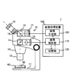
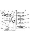
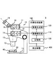
- FIG. 1 is a diagram showing the configuration of the microscope system 1.
- FIG. 2 is a diagram illustrating the configuration of the image processing device 100.
- FIG. 3 is a diagram illustrating the configuration of the optical system of the microscope 10.
- the microscope system 1 is a system for observing a sample by looking through the eyepiece lens 19.
- the sample to be observed by the microscope system 1 is, for example, the follicular fluid 50 contained in the container 40, and the microscope system 1 is used, for example, for egg inspection, which is one step of fertility treatment.
- the microscope system 1 includes at least a microscope 10, a photographing device 15, a projection device 17, which is an example of a superimposing device, and an image processing device 100.
- the microscope system 1 superimposes an auxiliary image on the optical image by projecting the auxiliary image on the image plane on which the optical image of the follicular fluid 50 is formed by the optical system of the microscope 10 using the projection device 17.
- the auxiliary image contains information that identifies the region where the presence of the egg is presumed (hereinafter referred to as the presumed region).
- the auxiliary image is created by the image processing device 100 based on the captured image of the follicular fluid captured by the imaging device 15.
- the user of the microscope system 1 observing the follicular fluid by looking through the eyepiece 19 can obtain information on the estimated region without taking his eyes off the eyepiece 19, so that the eggs can be compared in a short time. It becomes possible to find out easily. Therefore, according to the microscope system 1, it is possible to support the work of searching for an egg in the user's egg inspection.
- the microscope system 1 includes a microscope 10 including a photographing device 15 and a projection device 17, and an image processing device 100.
- the microscope 10 includes a stage 11 on which a container 40 containing a follicular fluid 50 is placed, an objective lens 12 mounted on a revolver 13, an imaging lens 18, and an eyepiece lens 19.
- the objective lens 12 and the imaging lens 18 form an optical image of the follicular fluid 50 on the image plane.
- the eyepiece 19 further magnifies the optical image formed on the image plane.
- the user of the microscope system 1 observes a virtual image in which the optical image is magnified by using the eyepiece lens 19.
- the microscope 10 also includes a splitter 14 arranged on the optical path between the objective lens 12 and the imaging lens 18, and a photographing device 15 arranged on the optical path branched by the splitter 14.
- the splitter 14 is, for example, a half mirror, but a variable beam splitter that varies the transmittance and the reflectance may be used.
- the photographing device 15 is, for example, a digital camera provided with an image pickup device, and acquires a photographed image of the follicular fluid 50.
- the image sensor is, for example, a two-dimensional image sensor such as a CCD image sensor or a CMOS image sensor.
- the microscope 10 further includes a splitter 16 arranged on the optical path between the objective lens 12 and the imaging lens 18, and a projection device 17 arranged on the optical path branched by the splitter 16.
- the splitter 16 is, for example, a half mirror, but a variable beam splitter that changes the transmittance and the reflectance may be used.
- the projection device 17 is, for example, a projector using a reflective liquid crystal device, a projector using a transmissive liquid crystal device, a projector using a digital mirror device, and the like.
- the projection device 17 projects an auxiliary image generated by the image processing device 100 on the image plane on the optical path of the microscope 10.
- the projection device 17 is an example of a superimposition device that superimposes an auxiliary image on an optical image of the follicular fluid 50 formed on the image plane by projecting the auxiliary image on the image plane.
- the image processing device 100 generates an auxiliary image based on the captured image acquired by the photographing device 15.
- the image processing device 100 includes an image analysis unit 110, an image generation unit 120, and a storage unit 130 as functional components related to the generation of an auxiliary image.
- the image analysis unit 110 performs image analysis including detection of an object targeting an egg on a captured image. Specifically, the image analysis unit 110 detects an object using, for example, a learned model stored in the storage unit 130.
- the algorithm of the trained model is not particularly limited, but may be, for example, a deep learning model such as SSD, YOLO, or FasterR-CNN.
- the image generation unit 120 generates an auxiliary image including information for specifying a region (estimated region) where the presence of an egg is estimated based on the result of image analysis of the image analysis unit 110. Specifically, the image generation unit 120 generates an image having a bounding box in the estimation region as an auxiliary image.
- the storage unit 130 stores a learned model that has learned the position of the egg with respect to the input image. That is, the trained model detects the target classified as an egg and outputs at least the position information of the egg. More specifically, the trained model outputs the position information of the egg and the probability of classification (classification confidence) indicating the certainty of the egg.
- the image processing device 100 may be a general-purpose computer or a dedicated computer.
- the image processing device 100 is not particularly limited to this configuration, but may have, for example, a physical configuration as shown in FIG.
- the image processing device 100 may include a processor 101, a storage device 102, an input device 103, an output device 104, and a communication device 105, which are connected to each other by a bus 106. May be good.
- the processor 101 may include hardware, which may include, for example, at least one of a circuit for processing digital signals and a circuit for processing analog signals.
- the processor 101 can include, for example, one or more circuit devices (eg, ICs) or one or more circuit elements (eg, resistors, capacitors) on a circuit board.
- the processor 101 may be a CPU (central processing unit). Further, various types of processors including GPU (Graphics processing unit) and DSP (Digital Signal Processor) may be used for the processor 101.
- the processor 101 may be a hardware circuit having an ASIC (Application Specific Integrated Circuit) or an FPGA (Field-Programmable Gate Array).
- the processor 101 can include an amplifier circuit, a filter circuit, and the like for processing an analog signal.
- the processor 101 functions as the image analysis unit 110 and the image generation unit 120 described above by executing the program stored in the storage device 102.
- the storage device 102 may include a memory and / or other storage device.
- the memory may be, for example, a random access memory (RAM).
- the memory may be a semiconductor memory such as SRAM (Static Random Access Memory) or DRAM (Dynamic Random Access Memory).
- the storage device 102 may include, for example, a register, a magnetic storage device such as a hard disk device, an optical storage device such as an optical disk device, an internal or external hard disk drive, a solid state storage device, a CD-ROM, a DVD, or other optical or magnetic. It may be a disk storage device or another storage device.
- the storage device 102 stores programs, trained models, and other data executed by the processor 101, and functions as the storage unit 130 described above.
- the storage device 102 is an example of a non-temporary computer-readable storage medium.
- the input device 103 is a device operated by a user of the microscope system 1 (for example, an embryo culture person).
- the input device 103 is, for example, a keyboard, a mouse, a touch panel, a voice input device, a foot pedal, or the like, and outputs an operation signal corresponding to an operation on the input device 103 to the processor 101.
- the output device 104 is, for example, a display device such as a liquid crystal display, a plasma display, an organic EL display, a CRT display, or an LED matrix panel.
- the output device 104 may further include an audio output device such as a speaker that outputs audio, a light emitting device such as a lamp or a light that outputs light, and a vibration device such as a vibrator that outputs vibration.
- the communication device 105 is a device that exchanges data with the microscope 10 and other devices.
- the communication device 105 may be a communication device that exchanges data by wire, or may be a communication device that exchanges data wirelessly.
- the program or learned model stored in the storage device 102 may be acquired by the communication device 105 from another device via the Internet.
- the egg inspection performed using the microscope 10 is a work performed by an embryo culture person while looking into the eyepiece lens 19 at a relatively low observation magnification. Therefore, it is desirable that the microscope 10 is a stereomicroscope capable of observing an object three-dimensionally at a low magnification. More specifically, for example, as shown in FIG. 3, the left eye system including the splitter 14a, the photographing device 15a, the splitter 16a, the projection device 17a, the imaging lens 18a, and the eyepiece 19a, the splitter 14b, and the photographing device 15b. It is desirable to have a binocular stereomicroscope having a splitter 16b, a projection device 17b, an imaging lens 18b, and a right eye system including an eyepiece 19b.
- FIG. 4 is a flowchart showing an example of the learning process according to the present embodiment.
- FIG. 5 is a diagram showing an example of a screen for creating a learning data set.
- FIG. 6 is a diagram illustrating an image included in the learning data set.
- the learning process shown in FIG. 4 may be performed by a computer different from the image processing device 100, and the image processing device 100 may acquire the completed trained model via a network or a recording medium. ..
- the window W1 shown in FIG. 5 is displayed.
- the window W1 shown in FIG. 5 is a screen for creating a learning data set, and the window W1 has an area R1 for selecting an image file of the follicular fluid and an image of the follicular fluid corresponding to the image file selected in the area R1.
- the area R2 for displaying the above is included.
- Step S1 When the worker building the trained model selects one image file from the plurality of image files listed in the area R1, the computer displays the still image of the follicular fluid corresponding to the selected image file in the area R2.
- the worker is, for example, an experienced embryo incubator. After that, the operator finds the egg from the still image displayed in the area R2, attaches a rectangular box B to the area containing the egg, and saves the file as shown in FIG.
- the computer creates a learning data set (step S2). Specifically, the computer cuts out the area surrounded by the rectangular box B from the image displayed in the area R2 and adds it to the learning data set. By repeating step S1 and step S2 on a plurality of still images, a sufficient amount of training data set is prepared.
- the cumulus cells may come off during egg collection when the egg is sucked from the follicle. Therefore, some of the eggs found at the time of egg inspection are surrounded by cumulus cells, while others have the cumulus cells peeled off and the corona radiata surrounding the egg is exposed. Therefore, it is desirable that the images included in the training data set include both an image of an egg surrounded by cumulus cells and an image of an egg detached from the cumulus cells.
- the data D1 included in the data set DS shown in FIG. 6 is an example of an image of an egg from which cumulus cells have been peeled off.
- a zona pellucida E2 and a corona radiata E3 surround the egg E1.
- data D2 is an example of an image of an egg surrounded by cumulus cells. It shows that the egg E1 (zona pellucida E2, corona radiata E3) is surrounded by cumulus cells E4.
- the computer trains the model that performs object detection on the egg using the training data set (step S3). That is, train, validate, and test the model.
- the data set created in step S2 may be divided into training data / verification data and test data. In that case, it is desirable that the training and validation data be used for both training and validation using cross-validation.
- the training data is data used for training the model
- the verification data is data used for verifying the model.
- the test data is data used for testing the model.
- the computer repeats the above processing until the model clears the test, and when it clears, that is, when learning is completed, the processing in FIG. 4 ends.
- the obtained trained model is stored in the storage unit 130 of the image processing device 100.
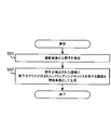
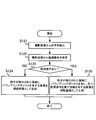
- FIG. 7 is a flowchart showing an example of the egg inspection support process according to the present embodiment.
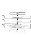
- FIG. 8 is a flowchart showing an example of the auxiliary image generation process according to the present embodiment.
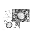
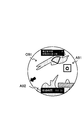
- FIG. 9 is an example of an image seen from the eyepiece lens 19.
- the egg inspection support method performed by the microscope system 1 will be described with reference to FIGS. 7 to 9.
- the egg inspection support process shown in FIG. 7 is started when the user of the microscope system 1 places a container 40 containing the follicular fluid 50 in the stage 11 and starts egg inspection.
- the microscope system 1 first projects an optical image onto the image plane (step S11).
- the optical system including the objective lens 12 and the imaging lens 18 is placed on the optical path of the microscope 10 based on the light from the follicular fluid 50, for example, the optical image O1 of the follicular fluid 50 as shown in FIG. To form.
- the microscope system 1 acquires a captured image at the same time as step S11 (step S12).
- the photographing device 15 acquires a photographed image of the follicular fluid based on the light from the follicular fluid 50, and outputs the photographed image to the image processing device 100.
- the microscope system 1 performs the auxiliary image generation process shown in FIG. 8 (step S13).
- the image processing device 100 first detects an egg from the captured image (step S21).
- the image analysis unit 110 detects an object targeting an egg by inputting a captured image as an input image into the trained model.
- the image processing device 100 After that, the image processing device 100 generates an image having a bounding box in the region where the egg is detected as an auxiliary image (step S22), and ends the auxiliary image generation process.
- the image generation unit 120 generates the auxiliary image A1 based on the object detection result by the image analysis unit 110. More specifically, the image generation unit 120 may determine only an object whose classification probability output from the image analysis unit 110 together with the position information of the object in object detection is equal to or greater than the threshold value, and classifies the object above the threshold value.
- Auxiliary image A1 having a bounding box in an area where an object having a probability of is present may be generated.
- the auxiliary image A1 shown in FIG. 9 shows a state in which a bounding box is formed in two regions where an egg is presumed to be present by object detection.
- the microscope system 1 When the auxiliary image generation process is completed, the microscope system 1 superimposes the auxiliary image on the optical image (step S14), and ends the process shown in FIG. 7.
- the projection device 17 projects the auxiliary image A1 generated in step S13 on the image plane on which the optical image O1 is formed, thereby superimposing the auxiliary image A1 on the optical image O1.
- the embryo culture person who is the user of the microscope system 1 searches for the egg while looking into the eyepiece lens 19 and looking at the image in which the optical image O1 and the auxiliary image A1 are superimposed as shown in FIG. be able to. Therefore, even an inexperienced embryo culture person can surely find an egg that is often overlooked, such as an egg isolated from the cumulus cells. Therefore, according to the microscope system 1, it is possible to support the search for an egg in egg inspection.
- FIG. 9 illustrates an auxiliary image A1 having a bounding box in an estimated region where an egg is estimated to be present by object detection, but the auxiliary image may include information for specifying the estimated region. Therefore, instead of the rectangular bounding box, the estimated area may be surrounded by an arbitrary shape such as a circle. Further, instead of surrounding the estimated region, the region where the egg exists may be specified by another method such as pointing to the estimated region with an arrow or the like.
- FIG. 10 is another example of the image seen from the eyepiece lens 19.
- the auxiliary image A1 including only the information for specifying the estimation area is illustrated, but the information output from the image analysis unit 110 usually includes the probability of classification in addition to the position information of the target. Is. Therefore, the image generation unit 120 may generate an auxiliary image by using the probability of classification in addition to the position information of the target, and the auxiliary image is information that specifies an estimated region, for example, as shown in FIG. In addition to the (bounding box), information on the probability of being classified as an egg may be included.
- the egg in the first bounding box was classified as an egg with a 95% probability
- the egg in the second bounding box was classified as an egg with an 80% probability. It is shown that it was done.
- the embryo cultivator makes a final decision as to whether or not the egg is an egg based on his or her initial opinion and the probability of classification when searching for an egg. You can make a good decision.
- the egg inspection time will be shortened by prioritizing the confirmation from the one with the highest classification probability.
- FIG. 11 is a flowchart showing an example of the auxiliary image generation process according to the present embodiment.
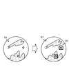
- FIG. 12 is yet another example of the image seen from the eyepiece lens 19.
- the image analysis unit 110 detects an egg in another captured image acquired before the captured image. It differs from the microscope system 1 shown in FIG. 1 in that the object tracking for estimating the current position of the image is performed. That is, in the present embodiment, the image analysis unit 110 performs image analysis including object detection and object tracking.
- the egg inspection support process according to the present embodiment is the same as the egg inspection support process shown in FIG.
- step S12 the microscope system performs the auxiliary image generation process shown in FIG.
- the image processing device 100 first detects an egg from the captured image (step S31). This process is the same as in step S21 of FIG.
- the image processing device 100 estimates the current position of the previously detected egg (step 32).
- the image analysis unit 110 tracks an object targeting an egg. Specifically, the image analysis unit 110 estimates the current position of the egg based on a plurality of frames of captured images including the latest captured image. Further, the image analysis unit 110 may determine only the target whose classification probability output in the object detection is equal to or greater than the threshold value as an egg, or may set only the target determined to be an egg as the object tracking target.
- the specific method of object tracking is not particularly limited, but it is desirable to adopt a robust method for occlusion in which the tracking target is hidden behind other objects.
- the current position of the egg may be estimated using a Kalman filter, a particle filter, or the like.
- the optical flow of the container may be calculated, and the current position of the egg may be estimated from the calculated optical flow.
- the image processing apparatus 100 After that, the image processing apparatus 100 generates an image having a bounding box in the region where the egg is detected and a second bounding box in the region including the estimated current position as an auxiliary image (step S33).
- the auxiliary image generation process is terminated.
- the image generation unit 120 generates an auxiliary image based on the object detection result and the object tracking result by the image analysis unit 110. Specifically, as shown in FIG.
- the image generation unit 120 has an auxiliary image having only a rectangular bounding box while all the eggs in the visual field are detected by object detection (auxiliary image A11, Auxiliary image A12) is generated, and if some eggs are hidden behind other cells, even if an auxiliary image (auxiliary image A13) having a rectangular bounding box and a fan-shaped bounding box is generated. good.
- the rectangular bounding box indicates the estimated region estimated by the object detection
- the fan-shaped bounding box indicates the region including the current position of the egg estimated by the object tracking.
- the microscope system When the auxiliary image generation process is completed, the microscope system superimposes the auxiliary image on the optical image (step S14), and ends the process shown in FIG. 7.
- the auxiliary image projected on the image plane is the auxiliary image. It shows how the image has changed as A11, the auxiliary image A12, and the auxiliary image A13.
- the microscope system according to the present embodiment can also support the search for an egg in egg inspection, as in the case of the microscope system 1.
- the embryo cultivator may move the container to move the field of view to another place, shake the container to move the egg hidden behind other cells, and so on. While such work may allow the egg to move in the container and detect a new egg by object detection, the previously detected egg is hidden behind other cells and disappears. It may end up.
- the microscope system according to the present embodiment since the object tracking is performed on the egg, the existence of the hidden egg can also be notified to the user. Therefore, according to the microscope system according to the present embodiment, it is possible to more strongly support the search for an egg in egg inspection.
- FIG. 13 is a flowchart showing an example of the auxiliary image generation process according to the present embodiment.
- FIG. 14 is yet another example of the image seen from the eyepiece lens 19.
- the microscope system according to the present embodiment (hereinafter, simply referred to as a microscope system) is similar to the microscope system according to the second actual embodiment in that the image analysis unit 110 performs object tracking in addition to object detection. ..
- the microscope system differs from the microscope system according to the second embodiment in that it notifies the user of the presence of eggs that have moved out of the field of view in addition to the presence of eggs in the field of view. More specifically, the microscope system performs egg inspection support processing including the auxiliary image generation processing shown in FIG. 13 instead of the auxiliary image generation processing shown in FIG.
- the egg inspection support method performed by the microscope system according to the present embodiment will be described with reference to FIGS. 13 and 14, focusing on the auxiliary image generation process.
- the microscope system performs the auxiliary image generation process shown in FIG.
- the image processing apparatus 100 first detects an egg from the captured image (step S41) and estimates the current position of the previously detected egg (step 42).
- the image processing apparatus 100 has a bounding box in the region where the egg is detected, has a second bounding box in the region including the estimated current position in the field of view, and has an estimated current position outside the field of view.
- An image having information indicating the direction of is generated as an auxiliary image (step S43), and the auxiliary image generation process is completed.
- the image generation unit 120 generates an auxiliary image based on the object detection result and the object tracking result by the image analysis unit 110. Specifically, as shown in FIG. 14, the image generation unit 120 has an auxiliary image (auxiliary image A21, auxiliary image A22) having only a rectangular bounding box while all the eggs are detected by object detection.
- auxiliary image A23 having a rectangular bounding box and a fan-shaped bounding box is generated, and some eggs are generated.
- an auxiliary image (auxiliary image A24) having a rectangular bounding box and an arrow mark is generated. Note that.
- the arrow mark is an example of information indicating the direction of the current position outside the field of view estimated by object tracking, and is an example of information indicating the direction in which the egg outside the field of view exists.
- FIG. 14 shows an auxiliary projected on the image plane when the optical image formed on the image plane by moving the container changes like the optical image O21, the optical image O22, the optical image O23, and the optical image O24. It shows how the image has changed like the auxiliary image A21, the auxiliary image A22, the auxiliary image A23, and the auxiliary image A24.
- the embryo cultivator can surely find the egg that is often overlooked. Further, according to the microscope system according to the present embodiment, since the object tracking is performed on the egg, it is possible to notify the user of the existence of the hidden egg or the existence of the egg that has moved out of the field of view. Therefore, according to the microscope system according to the present embodiment, it is possible to more strongly support the search for an egg in egg inspection.
- FIG. 15 is a diagram showing another example of the screen for creating the learning data set.
- FIG. 16 is a diagram showing still another example of the screen for creating the learning data set.
- FIG. 17 is a flowchart showing an example of the auxiliary image generation process according to the present embodiment.
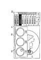
- FIG. 18 is yet another example of the image seen through the eyepiece 19.
- the image analysis unit 110 detects eggs by dividing them into a plurality of classes having different recommendations as collection targets in egg inspection by object detection. This is different from the microscope system 1 shown in FIG.
- the egg inspection support process according to the present embodiment is the same as the egg inspection support process shown in FIG. 7, except that the auxiliary image generation process shown in FIG. 8 is included instead of the auxiliary image generation process shown in FIG. be.
- the operator finds an egg from the still image displayed in the area R2 on the window W2 shown in FIG. 15, attaches a rectangular box B to the area containing the egg, and then further examines the egg. Judge the recommendation level as a collection target in the above and enter the recommendation level information in the input field C. Then, when the save operation of the worker is detected, the computer cuts out the area surrounded by the rectangular box B from the image displayed in the area R2 and learns it as an image of the class according to the input recommendation degree information. Add to the dataset for.
- the recommendation level information input by the worker may be egg maturity information, for example, "GV” indicating a degenerated egg which is a GV stage egg and "GV” indicating an immature egg which is an MI stage egg. MI ",” MII "indicating a mature egg which is a MII stage egg may be included. Further, the operator may input the recommendation degree information by distinguishing, for example, overripe eggs, moderately mature eggs, abnormal eggs and the like.
- the storage device 102 stores a trained model that has learned at least the position of the egg and the plurality of classes of the egg with respect to the input image.
- a sample image of the egg having a different maturity is displayed on the learning data set creation screen (window W2).
- the region R3 including the above may be displayed.
- step S12 the microscope system performs the auxiliary image generation process shown in FIG.
- the image processing device 100 first detects an egg from the captured image (step S51). This process is the same as the process of step S21 of FIG.
- the image processing device 100 After that, the image processing device 100 generates an image having a bounding box with an egg class in the estimation area as an auxiliary image (step S52), and ends the auxiliary image generation process.
- the image generation unit 120 generates an auxiliary image based on the object detection result by the image analysis unit 110. Specifically, the image generation unit 120 generates an auxiliary image A31 having information (GV, MI, MII) for identifying an egg class near a rectangular bounding box, for example, as shown in FIG.
- the microscope system When the auxiliary image generation process is completed, the microscope system superimposes the auxiliary image on the optical image (step S14), and ends the process shown in FIG. 7.
- the projection device 17 superimposes the auxiliary image A31 on the optical image O31, for example, as shown in FIG.
- the user can be notified of the recommendation level of the egg existing in the estimated region as well as the estimated region. Therefore, for example, when it is not necessary to collect all the eggs, it is possible to easily select the eggs to be collected.
- an example of notifying the user of the recommendation level by displaying character information that identifies the egg class is shown.
- a bounding box is created with a color corresponding to the egg class. You may notify the user of the recommendation level with.
- the recommendation level may be notified to the user by creating a bounding box having a shape corresponding to the egg class.
- FIG. 19 is a flowchart showing an example of the auxiliary image generation process according to the present embodiment.
- FIG. 20 is yet another example of the image seen through the eyepiece 19.
- the microscope system according to the fourth embodiment is different from the microscope system according to the fourth embodiment in that the image analysis unit 110 calculates the size of the egg detected by the object detection in the microscope system (hereinafter, simply referred to as a microscope system) according to the present embodiment. Is different. Further, the microscope system performs egg inspection support processing including the auxiliary image generation processing shown in FIG. 19 instead of the auxiliary image generation processing shown in FIG.
- the egg inspection support method performed by the microscope system according to the present embodiment will be described with reference to FIGS. 19 and 20, paying attention to the auxiliary image generation process.
- step S12 the microscope system performs the auxiliary image generation process shown in FIG.
- the image processing device 100 first detects an egg from the captured image (step S61). This process is the same as the process of step S21 of FIG.
- the image processing device 100 calculates the size of the egg (step S62).
- the image analysis unit 110 may calculate the size of the egg from the area of the recommended region detected by the object detection, for example.
- the size of the egg may be calculated from the size of the bounding box surrounding the recommended area. The size may be calculated in units of length such as diameter, or in units of area.
- the image processing device 100 After that, the image processing device 100 generates an image having a bounding box with an egg class and size in the estimated region as an auxiliary image (step S63), and ends the auxiliary image generation process.
- the image generation unit 120 has information for specifying the egg class (GV, MI, MII) and information for specifying the egg size (90 ⁇ m) near the rectangular bounding box. , 100 ⁇ m, 120 ⁇ m) to generate an auxiliary image A41.
- the microscope system When the auxiliary image generation process is completed, the microscope system superimposes the auxiliary image on the optical image (step S14), and ends the process shown in FIG. 7.
- the projection device 17 superimposes the auxiliary image A41 on the optical image O41, for example, as shown in FIG.
- the microscope system it is possible to notify the user of the recommended degree and size of the egg existing in the estimated region as well as the estimated region. Therefore, for example, when it is not necessary to collect all the eggs, it is possible to easily select the eggs to be collected.
- the microscope system may further perform object tracking.
- the display mode may be different between the egg detected by the object detection and the egg whose current position is estimated by the object tracking.
- the recommendation level information (class) and size may be displayed for the egg detected by the object detection, and the recommendation level for the egg whose current position is estimated by the object tracking. Only information (class) may be displayed.
- FIG. 21 shows a state in which the auxiliary image A51 is superimposed on the optical image O51. Further, in the auxiliary image A51, an egg detected by object detection is assigned a class and a size, and an egg whose existence is presumed by object tracking is assigned only a class.
- FIG. 22 is a diagram showing the configuration of the microscope system 2.
- FIG. 23 is a flowchart showing an example of the egg inspection support process according to the present embodiment.
- the microscope system 2 is different from the microscope system 1 in that it includes a notification device 200 for notifying the detection of an egg in object detection.
- the notification device 200 is, for example, an audio output device such as a speaker that outputs audio, a light emitting device such as a lamp or a light that outputs light, or a vibration device such as a vibrator that outputs vibration.
- the microscope system 2 performs the egg inspection support process shown in FIG. 23 instead of the egg inspection support process shown in FIG. 7.
- the egg inspection support method performed by the microscope system 2 will be described with reference to FIGS. 22 and 23.
- steps S71 to S74 shown in FIG. 23 is the same as the processing of steps S11 to S14 shown in FIG.
- the image processing apparatus 100 determines whether or not an egg is detected in the object detection in step S73 (step S75), and if it is determined that the egg is detected (step S75YES). ),
- the notification device 200 notifies the detection of the egg in the object detection (step S76).
- the notification method is not particularly limited, but the notification device 200 may, for example, emit a warning sound or the like to call attention, or may emit light to call attention. In addition, the detection of the egg may be notified by voice.
- the output device 104 of the image processing device 100 may also serve as the notification device 200.
- the microscope system 2 according to the present embodiment can also support the search for an egg in egg inspection, similarly to the microscope system 1 according to the first embodiment. Further, in addition to visually notifying the user of the existence of the egg by projecting an auxiliary image, the notification device 200 notifies the user of the existence of the egg more reliably. Can be done.
- FIG. 24 is a diagram showing the configuration of the microscope system 3.
- FIG. 25 is a flowchart showing an example of the egg inspection support process according to the present embodiment.
- FIG. 26 is yet another example of the image seen through the eyepiece 19.
- the microscope system 3 differs from the microscope system 1 in that the microscope 20 is provided instead of the microscope 10. Further, the microscope 20 is different from the microscope 10 in that the imaging device 21 is provided.
- the photographing device 21 is a device for acquiring and recording a moving image of a photographed image (second photographed image) of the space above the stage 11 including the container 40, and is a second photographing device.
- the imaging device 21 is installed mainly for the purpose of photographing the work of the embryo incubator on the stage 11.
- the microscope system 3 performs the egg inspection support process shown in FIG. 25 instead of the egg inspection support process shown in FIG. 7.
- the egg inspection support method performed by the microscope system 3 according to the present embodiment will be described with reference to FIGS. 24 to 26.
- steps S81, S82, and S84 shown in FIG. 25 is the same as the processing of steps S11 to S13 shown in FIG.
- step S83 the microscope system 3 acquires a second captured image of the space above the stage 11 with the photographing device 21. Here, a moving image is taken instead of a still image.
- the image processing apparatus 100 determines whether or not an egg is detected in the object detection in step S84 (step S85), and determines that no egg is detected. (Step S85NO), the projection device 17 is controlled, and the projection device 17 superimposes an auxiliary image on the optical image (step S86).
- the process of step S86 is the same as the process of step S14 shown in FIG.
- the image processing device 100 controls the projection device 17, and the projection device 17 superimposes the auxiliary image and the moving image of the second captured image on the optical image.
- Step S87 That is, under the control of the image processing device 100, the photographing device 21 records a moving image of the second captured image including the frame at the time when the egg is detected by the object detection, and the projection device 17 records the moving image as shown in FIG.
- the recorded moving image A62 is superimposed on the optical image O62 together with the auxiliary image A61.
- the work of the embryo cultivator immediately before the egg detection was recorded when the optical image formed on the image plane changed from the optical image O61 in which the egg was not detected to the optical image O62 in which the egg was detected. It shows how the moving image A62 is displayed together with the auxiliary image A61.
- the microscope system 3 according to the present embodiment can also support the search for an egg in egg inspection, similarly to the microscope system 1 according to the first embodiment. Further, in the microscope system 3, details of the work performed by the embryo cultivator to detect the egg, for example, information such as how to tilt and move the container are provided to the embryo cultivator using a moving image. Therefore, according to the microscope system 3, it is possible to provide an embryo cultivator with an opportunity to learn a desirable work procedure for discovering an egg.
- FIG. 27 is a flowchart showing an example of the auxiliary image generation process according to the present embodiment.
- FIG. 28 is yet another example of the image seen through the eyepiece 19.
- the image analysis unit 110 performs a process of recognizing that an egg has been collected from the follicular fluid 50 in addition to object detection and object tracking. The point is different from the microscope system according to the third actual form. Further, the microscope system performs egg inspection support processing including the auxiliary image generation processing shown in FIG. 27 instead of the auxiliary image generation processing shown in FIG.
- the egg inspection support method performed by the microscope system according to the present embodiment will be described with reference to FIGS. 27 and 28, focusing on the auxiliary image generation process.
- step S91 shown in FIG. 27 is the same as the process of step S41 shown in FIG.
- the image processing device 100 detects the collection of eggs (step S92). Specifically, the image analysis unit 110 performs a process of recognizing that an egg has been collected from the follicular fluid 50 based on a moving image of a captured image captured by the imaging device 15. Further, the image processing apparatus 100 estimates the current position of the previously detected egg (step S93).
- the process of step S93 is the same as the process of step S42 shown in FIG. 13, except that the egg collected in step S92 is excluded from the tracking target.
- the image processing apparatus 100 has a bounding box in the region where the egg is detected, has a second bounding box in the region including the estimated current position in the visual field, and has an estimated direction of the current position outside the visual field.
- An image having an arrow mark pointing to and containing information indicating the egg inspection status is generated as an auxiliary image (step S94), and the auxiliary image generation process is completed. It is desirable that the information indicating the egg inspection status included in the auxiliary image includes, for example, the number of detected eggs and the number of collected eggs, as shown in FIG. 28.
- FIG. 28 shows the state before and after collecting the egg with a pipette.
- the optical image O71 before egg collection is superposed with the auxiliary image A71 showing the number of detected eggs 4 and the number of collected eggs 0, whereas the optical image O72 after egg collection has 3 detected eggs.
- An auxiliary image A72 showing the number of collected eggs 1 is superimposed.
- FIG. 29 is a diagram showing the configuration of the microscope system 4.
- FIG. 30 is a flowchart showing an example of the egg inspection support process according to the present embodiment.
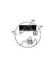
- FIG. 31 is yet another example of the image seen from the eyepiece lens 19.
- the microscope system 4 is different from the microscope system 1 in that the identification device 300 is provided. Further, the identification device 300 is, for example, a QR code (registered trademark) reader or the like, and is a device for acquiring identification information added to the container 40.
- the microscope system 4 performs the egg inspection support process shown in FIG. 30 instead of the egg inspection support process shown in FIG. 7.
- the egg inspection support method performed by the microscope system 4 according to the present embodiment will be described with reference to FIGS. 29 to 31.
- the microscope system 4 first acquires identification information (step S101).
- the embryo cultivator brings the identification label (QR code) attached to the container 40 closer to the identification device 300 before arranging the container 40 on the stage 11.
- the identification device 300 reads the identification label and acquires the identification information.
- the identification information includes information on the provider of the follicular fluid 50 in the container 40, or link information indicating a place where the information on the donor is stored.
- the acquired identification information is output from the identification device 300 to the image processing device 100.
- the microscope system 4 performs the processes from step S102 to step S104.
- the processing of steps S102 to S104 is the same as the processing of steps S11 to S13 shown in FIG.
- the microscope system 4 generates a second auxiliary image (step S105).
- the image generation unit 120 generates a second auxiliary image A82 including information on the donor of the follicular fluid 50, as shown in FIG. 31, for example, based on the identification information acquired in step S101.
- the second auxiliary image A82 is different from the auxiliary image generated based on the captured image in that it is generated based on the identification information.
- the second auxiliary image A82 includes information such as the ID and name of the provider of the follicular fluid 50, the position of the follicle (ovary) from which the follicular fluid 50 was collected, the order of collecting the follicular fluid 50, and the amount of collection. There is.
- FIG. 31 shows a state in which the optical image O81, the auxiliary image A81, and the second auxiliary image A82 are superimposed.
- FIG. 32 is a diagram showing the configuration of the microscope system 5.
- FIG. 33 is a flowchart showing an example of the egg inspection support process according to the present embodiment.
- FIG. 34 is yet another example of the image seen from the eyepiece lens 19.
- the microscope system 5 is different from the microscope system 1 in that it includes a detection device 400.
- the detection device 400 is, for example, a sensor that detects that the container 40 is placed on the stage 11, and is a device that detects the start of egg inspection.
- the microscope system 5 performs the egg inspection support process shown in FIG. 33 instead of the egg inspection support process shown in FIG. 7.
- the egg inspection support method performed by the microscope system 5 according to the present embodiment will be described with reference to FIGS. 32 to 34.
- the microscope system 5 starts the measurement with the timer (step S111).
- the timer may be included in the processor 101, for example, and measures the elapsed time after detecting a predetermined event. In this example, the timer measures the elapsed time after detecting the detection signal from the detection device 400.
- step S112 performs the processes from step S112 to step S114.
- the processing of steps S112 and S113 is the same as the processing of steps S11 and S12 shown in FIG.
- step S114 is the same as the auxiliary image generation process shown in FIG. 27.
- the microscope system 5 generates a third auxiliary image (step S115).
- the image generation unit 120 generates, for example, a third auxiliary image A92 including the elapsed time measured by the timer, as shown in FIG. 34.
- the third auxiliary image A92 is different from the auxiliary image generated based on the captured image in that it is generated based on the measurement result of the timer.
- the microscope system 5 (projection device 17) superimposes the auxiliary image and the third auxiliary image on the optical image (step S116), and ends the process shown in FIG. 33.
- FIG. 34 shows a state in which the optical image O91, the auxiliary image A91, and the third auxiliary image A92 are superimposed.
- the user can perform the egg inspection work while constantly checking the elapsed time from the start of the egg inspection.
- the start of egg inspection may be detected based on, for example, an operation signal from the input device 103. .. That is, the input device 103 may function as the detection device 400.
- FIG. 35 is a diagram showing the configuration of the microscope system 6.
- FIG. 36 is a flowchart showing an example of the auxiliary image generation process according to the present embodiment.
- Each of FIGS. 37 to 39 is yet another example of the image seen through the eyepiece 19.
- the microscope system 6 includes a notification device 200 (first notification device) for notifying the detection of eggs and a second notification device 500 for notifying the recommended operation, and the image analysis unit 110 adds to the object detection. It differs from the microscope system 2 in that the process of estimating the recommended operation is performed.
- the second notification device 500 is, for example, an audio output device such as a speaker that outputs audio.
- the microscope system 6 is different from the microscope system 2 in that the auxiliary image generation process shown in FIG. 36 is performed in the egg inspection support process shown in FIG. 23.
- the egg inspection support method performed by the microscope system 6 will be described with reference to FIGS. 35 to 39.
- the microscope system 6 performs the auxiliary image generation process shown in FIG. 36.
- the image processing device 100 first detects an egg from the captured image (step S121). This process is the same as the process of step S21 of FIG.
- the image processing device 100 estimates the recommended operation from the captured image (step S122).
- the image analysis unit 110 estimates a recommended operation to be performed during egg inspection based on the captured image. This process may be implemented, for example, by a trained model. For example, in a situation where the optical image O101 as shown in FIG. 37 can be obtained, it is difficult to find an egg because there are many bubbles. Therefore, the image analysis unit 110 may estimate the operation of shaking the container 40 as a recommended operation. Further, for example, in a situation where the optical image O111 as shown in FIG. 38 can be obtained, the contrast of the image is low and it is difficult to find the egg. Therefore, the image analysis unit 110 may estimate the operation of operating the focusing unit to adjust the focus as a recommended operation.
- the image analysis unit 110 recommends stopping the egg inspection with the current follicular fluid 50. You may estimate.
- step S123 the image processing device 100 determines whether or not the recommended operation is estimated in step S122 (step S123). If the recommended operation was not estimated, that is, if there was no recommended operation (step S123NO), the image processing apparatus 100 generated an image having a bounding box in the region where the egg was detected as an auxiliary image (step S124). , Ends the auxiliary image generation process.
- step S124 is the same as the process of step S22 of FIG.
- the image processing apparatus 100 When the recommended operation is estimated, that is, when there is a recommended operation (step S123YES), the image processing apparatus 100 has a bounding box in the region where the egg is detected, and the image contains information representing the recommended operation. Is generated as an auxiliary image (step S125), and the auxiliary image generation process is completed.
- the image generation unit 120 if the operation of shaking the container 40 is estimated as a recommended operation, the image generation unit 120 generates, for example, the auxiliary image A101 shown in FIG. 37. Further, if the operation of adjusting the focus is estimated as a recommended operation, the image generation unit 120 generates, for example, the auxiliary image A111 shown in FIG. 38. Further, if the operation of stopping the egg inspection is estimated as a recommended operation, the image generation unit 120 generates, for example, the auxiliary image A122 shown in FIG. 39.
- the microscope system 6 (projection device 17) superimposes an auxiliary image on the optical image.
- the microscope system 6 notifies the detection of the egg by using the notification device 200 when the egg is detected, and notifies the recommended operation by using the second notification device 500 when the recommended operation is estimated. do. As a result, the user can more reliably recognize the recommended operation.
- FIG. 40 is a diagram showing the configuration of the microscope system 7.
- the projection device 17 arranged on the optical path branched from the optical path between the objective lens 12 and the eyepiece lens 19 is illustrated, but the device for superimposing the auxiliary image is an objective as shown in FIG. 40. It may be arranged on the optical path between the lens 12 and the eyepiece 19.
- the microscope system 7 includes a microscope 30 including a display device 31 on an image plane on which an optical image is formed, and an image processing device 100.
- the display device 31 is a transmissive image display device, and is an example of a superimposition device that superimposes an auxiliary image on an optical image by displaying the auxiliary image directly on the image plane. Similar to the microscope system 1, the microscope system 7 can also support the user's search for eggs in egg inspection.
- FIG. 41 is a diagram showing the configuration of the microscope system 8.
- the photographing device 15 and the projection device 17 are provided in the microscope 10, and the image processing device 100 independent of the microscope 10 exchanges data between the photographing device 15 and the projection device 17, thereby forming an auxiliary image as an optical image.
- the photographing device, the projection device, and the image processing device may be integrally configured as shown in FIG. 41.
- the projection unit 600 mounted between the microscope main body 70 and the lens barrel 80 of the microscope 60 includes an imaging device 15, a projection device 17, and an image processing device (image analysis unit 110, image generation unit 120, A storage unit 130) may be provided.
- an image processing device image analysis unit 110, image generation unit 120, A storage unit 130
- Microscope system 10, 20, 30, 60 ... Microscope, 11 ... Stage, 12 ... Objective lens, 15, 15a, 15b, 21 ... Imaging device, 17, 17a , 17b ... Projection device, 18, 18a, 18b ... Imaging lens, 19 ... Eyepiece, 31 ... Display device, 40 ... Container, 50 ... Follicle fluid, 70 ... Microscope body, 80 ... lens barrel, 100 ... image processing device, 101 ... processor, 102 ... storage device, 110 ... image analysis unit, 120 ... image generation unit, 130. .. Storage unit, 200 ... Notification device, 300 ... Identification device, 400 ... Detection device, 500 ... Second notification device, 600 ... Projection unit
Landscapes
- Physics & Mathematics (AREA)
- Engineering & Computer Science (AREA)
- Multimedia (AREA)
- Chemical & Material Sciences (AREA)
- Analytical Chemistry (AREA)
- General Physics & Mathematics (AREA)
- Optics & Photonics (AREA)
- Computer Vision & Pattern Recognition (AREA)
- Microscoopes, Condenser (AREA)
Priority Applications (3)
| Application Number | Priority Date | Filing Date | Title |
|---|---|---|---|
| JP2022511750A JPWO2021200002A1 (https=) | 2020-03-31 | 2021-03-10 | |
| CN202180025339.5A CN115552309A (zh) | 2020-03-31 | 2021-03-10 | 显微镜系统、投影单元以及检卵辅助方法 |
| EP21779247.2A EP4130842A4 (en) | 2020-03-31 | 2021-03-10 | MICROSCOPE SYSTEM, PROJECTION UNIT AND METHOD FOR ASSISTING AN EGG TEST |
Applications Claiming Priority (2)
| Application Number | Priority Date | Filing Date | Title |
|---|---|---|---|
| JP2020-063283 | 2020-03-31 | ||
| JP2020063283 | 2020-03-31 |
Publications (1)
| Publication Number | Publication Date |
|---|---|
| WO2021200002A1 true WO2021200002A1 (ja) | 2021-10-07 |
Family
ID=77928713
Family Applications (1)
| Application Number | Title | Priority Date | Filing Date |
|---|---|---|---|
| PCT/JP2021/009684 Ceased WO2021200002A1 (ja) | 2020-03-31 | 2021-03-10 | 顕微鏡システム、投影ユニット、及び、検卵支援方法 |
Country Status (4)
| Country | Link |
|---|---|
| EP (1) | EP4130842A4 (https=) |
| JP (1) | JPWO2021200002A1 (https=) |
| CN (1) | CN115552309A (https=) |
| WO (1) | WO2021200002A1 (https=) |
Cited By (1)
| Publication number | Priority date | Publication date | Assignee | Title |
|---|---|---|---|---|
| JP2023163525A (ja) * | 2022-04-28 | 2023-11-10 | 株式会社エビデント | 顕微鏡システム、投影ユニット、画像投影方法 |
Families Citing this family (3)
| Publication number | Priority date | Publication date | Assignee | Title |
|---|---|---|---|---|
| CN117008311A (zh) * | 2023-08-07 | 2023-11-07 | 西藏阜康医疗股份有限公司 | 一种医学用卵冠丘复合体自动识别系统及方法 |
| CN117218918B (zh) * | 2023-09-28 | 2025-07-29 | 西藏阜康医疗股份有限公司 | 一种基于卵冠丘复合体仿制物的捡卵培训装置 |
| CN117982214B (zh) * | 2024-04-07 | 2024-07-23 | 安徽医科大学第一附属医院 | 一种快速捡卵用辅助识别方法及系统 |
Citations (6)
| Publication number | Priority date | Publication date | Assignee | Title |
|---|---|---|---|---|
| JP2008109552A (ja) * | 2006-10-27 | 2008-05-08 | Sanyo Electric Co Ltd | 追跡機能付き撮像装置 |
| WO2012150689A1 (ja) | 2011-05-02 | 2012-11-08 | オリンパス株式会社 | 顕微鏡、及び、顕微鏡を用いた顕微授精方法 |
| JP2016526949A (ja) * | 2013-05-31 | 2016-09-08 | ラブマン オートメーション リミテッドLabman Automation Limited | 体外受精採卵チャンバ |
| WO2018231204A1 (en) * | 2017-06-13 | 2018-12-20 | Google Llc | Augmented reality microscope for pathology |
| JP2019533847A (ja) * | 2016-08-12 | 2019-11-21 | ヴェリリー ライフ サイエンシズ エルエルシー | 高度な病理診断 |
| WO2020138279A1 (ja) * | 2018-12-28 | 2020-07-02 | オリンパス株式会社 | 顕微鏡システム |
Family Cites Families (4)
| Publication number | Priority date | Publication date | Assignee | Title |
|---|---|---|---|---|
| JP5557218B2 (ja) * | 2012-07-27 | 2014-07-23 | 国立大学法人 千葉大学 | 精子機能の検査方法 |
| IL251134B (en) * | 2016-05-17 | 2018-03-29 | Sheena Haim | A system and method for monitoring and managing laboratory procedures |
| JP2021515240A (ja) * | 2018-04-12 | 2021-06-17 | グーグル エルエルシーGoogle LLC | 定量的バイオマーカデータのオーバレイを有する病理学用拡張現実顕微鏡 |
| WO2020059522A1 (ja) * | 2018-09-21 | 2020-03-26 | 公立大学法人横浜市立大学 | 生殖医療支援システム |
-
2021
- 2021-03-10 EP EP21779247.2A patent/EP4130842A4/en not_active Withdrawn
- 2021-03-10 JP JP2022511750A patent/JPWO2021200002A1/ja active Pending
- 2021-03-10 WO PCT/JP2021/009684 patent/WO2021200002A1/ja not_active Ceased
- 2021-03-10 CN CN202180025339.5A patent/CN115552309A/zh active Pending
Patent Citations (6)
| Publication number | Priority date | Publication date | Assignee | Title |
|---|---|---|---|---|
| JP2008109552A (ja) * | 2006-10-27 | 2008-05-08 | Sanyo Electric Co Ltd | 追跡機能付き撮像装置 |
| WO2012150689A1 (ja) | 2011-05-02 | 2012-11-08 | オリンパス株式会社 | 顕微鏡、及び、顕微鏡を用いた顕微授精方法 |
| JP2016526949A (ja) * | 2013-05-31 | 2016-09-08 | ラブマン オートメーション リミテッドLabman Automation Limited | 体外受精採卵チャンバ |
| JP2019533847A (ja) * | 2016-08-12 | 2019-11-21 | ヴェリリー ライフ サイエンシズ エルエルシー | 高度な病理診断 |
| WO2018231204A1 (en) * | 2017-06-13 | 2018-12-20 | Google Llc | Augmented reality microscope for pathology |
| WO2020138279A1 (ja) * | 2018-12-28 | 2020-07-02 | オリンパス株式会社 | 顕微鏡システム |
Non-Patent Citations (1)
| Title |
|---|
| See also references of EP4130842A4 |
Cited By (1)
| Publication number | Priority date | Publication date | Assignee | Title |
|---|---|---|---|---|
| JP2023163525A (ja) * | 2022-04-28 | 2023-11-10 | 株式会社エビデント | 顕微鏡システム、投影ユニット、画像投影方法 |
Also Published As
| Publication number | Publication date |
|---|---|
| EP4130842A4 (en) | 2024-05-15 |
| JPWO2021200002A1 (https=) | 2021-10-07 |
| EP4130842A1 (en) | 2023-02-08 |
| CN115552309A (zh) | 2022-12-30 |
Similar Documents
| Publication | Publication Date | Title |
|---|---|---|
| WO2021200002A1 (ja) | 顕微鏡システム、投影ユニット、及び、検卵支援方法 | |
| CN112784672B (zh) | 基于计算机视觉的手术场景评估 | |
| US11594051B2 (en) | Microscope system and projection unit | |
| CN115103648A (zh) | 器械跟踪机器 | |
| CN104487014B (zh) | 手术系统中有效的交互式出血检测 | |
| RU2714264C2 (ru) | Системы, способы и компьютерочитаемые носители для выявления вероятного влияния медицинского состояния на пациента | |
| JP2021047911A (ja) | 高度な病理診断 | |
| EP4130843A1 (en) | Microscope system, projection unit, and sperm sorting assistance method | |
| JP2019532352A (ja) | 組織標本の組織学的検査のためのシステム | |
| CA3188627A1 (en) | Annotation data collection using gaze-based tracking | |
| TW202105245A (zh) | 用於分析活檢樣本影像以決定其癌變機率之方法 | |
| US20200074647A1 (en) | Smart glasses and method of selectively tracking target of visual cognition | |
| JP7580169B1 (ja) | 精子選別補助装置、精子選別補助システム、及び精子選別補助プログラム | |
| CN112543940A (zh) | 针对外科手术视频的主导工具检测系统 | |
| JP2018000048A (ja) | 多能性幹細胞の無染色評価支援方法、プログラム、演算装置 | |
| US11961230B2 (en) | Discerning device, cell mass discerning method, and computer program | |
| US11169079B2 (en) | Captured image evaluation apparatus, captured image evaluation method, and captured image evaluation program | |
| JP2008064534A (ja) | 細胞画像処理装置および細胞画像処理方法 | |
| JPWO2018003063A1 (ja) | 画像選択装置、画像選択方法、画像選択プログラム、表示装置、演算装置 | |
| US10963698B2 (en) | Tool handedness determination for surgical videos | |
| ES2904749T3 (es) | Método y sistema para ayudar a la exploración visual de una imagen durante una búsqueda de objetivo | |
| CN111289510B (zh) | 体外诊断仪、图像切换方法和可读存储介质 | |
| CN118469811A (zh) | 基于眼底图像的自动拼接方法、展示方法及装置 | |
| Kim et al. | Enhanced Surgical Tool Detection Using Oriented Bounding Boxes in Endoscopic Videos | |
| JP7693533B2 (ja) | 顕微鏡システム、投影ユニット、及び、選別支援方法 |
Legal Events
| Date | Code | Title | Description |
|---|---|---|---|
| 121 | Ep: the epo has been informed by wipo that ep was designated in this application |
Ref document number: 21779247 Country of ref document: EP Kind code of ref document: A1 |
|
| ENP | Entry into the national phase |
Ref document number: 2022511750 Country of ref document: JP Kind code of ref document: A |
|
| NENP | Non-entry into the national phase |
Ref country code: DE |
|
| ENP | Entry into the national phase |
Ref document number: 2021779247 Country of ref document: EP Effective date: 20221031 |