WO2021199775A1 - 車両用加熱装置 - Google Patents
車両用加熱装置 Download PDFInfo
- Publication number
- WO2021199775A1 WO2021199775A1 PCT/JP2021/006335 JP2021006335W WO2021199775A1 WO 2021199775 A1 WO2021199775 A1 WO 2021199775A1 JP 2021006335 W JP2021006335 W JP 2021006335W WO 2021199775 A1 WO2021199775 A1 WO 2021199775A1
- Authority
- WO
- WIPO (PCT)
- Prior art keywords
- heat medium
- heating
- cooling water
- vehicle
- upstream
- Prior art date
- Legal status (The legal status is an assumption and is not a legal conclusion. Google has not performed a legal analysis and makes no representation as to the accuracy of the status listed.)
- Ceased
Links
Images


Classifications
-
- B—PERFORMING OPERATIONS; TRANSPORTING
- B60—VEHICLES IN GENERAL
- B60H—ARRANGEMENTS OF HEATING, COOLING, VENTILATING OR OTHER AIR-TREATING DEVICES SPECIALLY ADAPTED FOR PASSENGER OR GOODS SPACES OF VEHICLES
- B60H1/00—Heating, cooling or ventilating devices
- B60H1/22—Heating, cooling or ventilating devices the heat source being other than the propulsion plant
-
- B—PERFORMING OPERATIONS; TRANSPORTING
- B60—VEHICLES IN GENERAL
- B60K—ARRANGEMENT OR MOUNTING OF PROPULSION UNITS OR OF TRANSMISSIONS IN VEHICLES; ARRANGEMENT OR MOUNTING OF PLURAL DIVERSE PRIME-MOVERS IN VEHICLES; AUXILIARY DRIVES FOR VEHICLES; INSTRUMENTATION OR DASHBOARDS FOR VEHICLES; ARRANGEMENTS IN CONNECTION WITH COOLING, AIR INTAKE, GAS EXHAUST OR FUEL SUPPLY OF PROPULSION UNITS IN VEHICLES
- B60K6/00—Arrangement or mounting of plural diverse prime-movers for mutual or common propulsion, e.g. hybrid propulsion systems comprising electric motors and internal combustion engines
- B60K6/20—Arrangement or mounting of plural diverse prime-movers for mutual or common propulsion, e.g. hybrid propulsion systems comprising electric motors and internal combustion engines the prime-movers consisting of electric motors and internal combustion engines, e.g. HEVs
- B60K6/42—Arrangement or mounting of plural diverse prime-movers for mutual or common propulsion, e.g. hybrid propulsion systems comprising electric motors and internal combustion engines the prime-movers consisting of electric motors and internal combustion engines, e.g. HEVs characterised by the architecture of the hybrid electric vehicle
- B60K6/48—Parallel type
- B60K6/485—Motor-assist type
-
- B—PERFORMING OPERATIONS; TRANSPORTING
- B60—VEHICLES IN GENERAL
- B60L—PROPULSION OF ELECTRICALLY-PROPELLED VEHICLES; SUPPLYING ELECTRIC POWER FOR AUXILIARY EQUIPMENT OF ELECTRICALLY-PROPELLED VEHICLES; ELECTRODYNAMIC BRAKE SYSTEMS FOR VEHICLES IN GENERAL; MAGNETIC SUSPENSION OR LEVITATION FOR VEHICLES; MONITORING OPERATING VARIABLES OF ELECTRICALLY-PROPELLED VEHICLES; ELECTRIC SAFETY DEVICES FOR ELECTRICALLY-PROPELLED VEHICLES
- B60L1/00—Supplying electric power to auxiliary equipment of vehicles
-
- B—PERFORMING OPERATIONS; TRANSPORTING
- B60—VEHICLES IN GENERAL
- B60L—PROPULSION OF ELECTRICALLY-PROPELLED VEHICLES; SUPPLYING ELECTRIC POWER FOR AUXILIARY EQUIPMENT OF ELECTRICALLY-PROPELLED VEHICLES; ELECTRODYNAMIC BRAKE SYSTEMS FOR VEHICLES IN GENERAL; MAGNETIC SUSPENSION OR LEVITATION FOR VEHICLES; MONITORING OPERATING VARIABLES OF ELECTRICALLY-PROPELLED VEHICLES; ELECTRIC SAFETY DEVICES FOR ELECTRICALLY-PROPELLED VEHICLES
- B60L50/00—Electric propulsion with power supplied within the vehicle
- B60L50/10—Electric propulsion with power supplied within the vehicle using propulsion power supplied by engine-driven generators, e.g. generators driven by combustion engines
- B60L50/16—Electric propulsion with power supplied within the vehicle using propulsion power supplied by engine-driven generators, e.g. generators driven by combustion engines with provision for separate direct mechanical propulsion
-
- B—PERFORMING OPERATIONS; TRANSPORTING
- B60—VEHICLES IN GENERAL
- B60W—CONJOINT CONTROL OF VEHICLE SUB-UNITS OF DIFFERENT TYPE OR DIFFERENT FUNCTION; CONTROL SYSTEMS SPECIALLY ADAPTED FOR HYBRID VEHICLES; ROAD VEHICLE DRIVE CONTROL SYSTEMS FOR PURPOSES NOT RELATED TO THE CONTROL OF A PARTICULAR SUB-UNIT
- B60W10/00—Conjoint control of vehicle sub-units of different type or different function
- B60W10/30—Conjoint control of vehicle sub-units of different type or different function including control of auxiliary equipment, e.g. air-conditioning compressors or oil pumps
-
- B—PERFORMING OPERATIONS; TRANSPORTING
- B60—VEHICLES IN GENERAL
- B60W—CONJOINT CONTROL OF VEHICLE SUB-UNITS OF DIFFERENT TYPE OR DIFFERENT FUNCTION; CONTROL SYSTEMS SPECIALLY ADAPTED FOR HYBRID VEHICLES; ROAD VEHICLE DRIVE CONTROL SYSTEMS FOR PURPOSES NOT RELATED TO THE CONTROL OF A PARTICULAR SUB-UNIT
- B60W20/00—Control systems specially adapted for hybrid vehicles
-
- F—MECHANICAL ENGINEERING; LIGHTING; HEATING; WEAPONS; BLASTING
- F01—MACHINES OR ENGINES IN GENERAL; ENGINE PLANTS IN GENERAL; STEAM ENGINES
- F01P—COOLING OF MACHINES OR ENGINES IN GENERAL; COOLING OF INTERNAL-COMBUSTION ENGINES
- F01P3/00—Liquid cooling
- F01P3/20—Cooling circuits not specific to a single part of engine or machine
-
- F—MECHANICAL ENGINEERING; LIGHTING; HEATING; WEAPONS; BLASTING
- F01—MACHINES OR ENGINES IN GENERAL; ENGINE PLANTS IN GENERAL; STEAM ENGINES
- F01P—COOLING OF MACHINES OR ENGINES IN GENERAL; COOLING OF INTERNAL-COMBUSTION ENGINES
- F01P7/00—Controlling of coolant flow
- F01P7/14—Controlling of coolant flow the coolant being liquid
-
- Y—GENERAL TAGGING OF NEW TECHNOLOGICAL DEVELOPMENTS; GENERAL TAGGING OF CROSS-SECTIONAL TECHNOLOGIES SPANNING OVER SEVERAL SECTIONS OF THE IPC; TECHNICAL SUBJECTS COVERED BY FORMER USPC CROSS-REFERENCE ART COLLECTIONS [XRACs] AND DIGESTS
- Y02—TECHNOLOGIES OR APPLICATIONS FOR MITIGATION OR ADAPTATION AGAINST CLIMATE CHANGE
- Y02T—CLIMATE CHANGE MITIGATION TECHNOLOGIES RELATED TO TRANSPORTATION
- Y02T10/00—Road transport of goods or passengers
- Y02T10/60—Other road transportation technologies with climate change mitigation effect
- Y02T10/62—Hybrid vehicles
-
- Y—GENERAL TAGGING OF NEW TECHNOLOGICAL DEVELOPMENTS; GENERAL TAGGING OF CROSS-SECTIONAL TECHNOLOGIES SPANNING OVER SEVERAL SECTIONS OF THE IPC; TECHNICAL SUBJECTS COVERED BY FORMER USPC CROSS-REFERENCE ART COLLECTIONS [XRACs] AND DIGESTS
- Y02—TECHNOLOGIES OR APPLICATIONS FOR MITIGATION OR ADAPTATION AGAINST CLIMATE CHANGE
- Y02T—CLIMATE CHANGE MITIGATION TECHNOLOGIES RELATED TO TRANSPORTATION
- Y02T10/00—Road transport of goods or passengers
- Y02T10/60—Other road transportation technologies with climate change mitigation effect
- Y02T10/7072—Electromobility specific charging systems or methods for batteries, ultracapacitors, supercapacitors or double-layer capacitors
Definitions
- the present invention relates to a vehicle heating device applied to a vehicle provided with a driving source for traveling such as an engine.
- a drive source for running a vehicle such as an engine and a heat exchanger for heating the air supplied to the vehicle interior are connected in series with each other, and the drive source and the heat exchanger are connected.
- a heat medium circuit for circulating a heat medium for heat exchange and a heat medium heating unit for heating a heat medium passing through the heat medium circuit are known (see, for example, Patent Document 1).
- the vehicle heating device heats the heat medium flowing through the heat medium circuit by the heat medium heating unit to perform a warm-up operation in which the drive source is heated by the heat medium, and at the same time, heat is generated in the heat exchanger. It is possible to perform a heating operation that heats the air supplied to the vehicle interior by using a medium.
- the drive source is arranged on the upstream side of the heat exchanger and the heat medium heating unit is arranged on the upstream side of the drive source in the distribution direction of the heat medium of the heat medium circuit. Therefore, in the vehicle heating device, when the warm-up operation and the heating operation are performed at the same time, the heat medium heated in the heat medium heating unit dissipates heat in the drive source and then supplies the heat medium to the vehicle interior in the heat exchanger. The heat is exchanged with the air to be supplied, the amount of heat for heating the air supplied to the vehicle interior is insufficient, and it may take a long time to raise the temperature of the vehicle interior to a target temperature.
- An object of the present invention is to provide a vehicle heating device capable of promptly completing the warm-up operation of the drive source and rapidly raising the temperature inside the vehicle interior to a target temperature.
- a drive source for traveling the vehicle and a heat exchanger for heating the air supplied to the vehicle interior are connected in series with each other, and the drive source of the drive source is connected.
- the vehicle heating device of the present invention acquires the required heating amount, which is the sum of the heating amount required in the warm-up operation and the heating amount required in the heating operation, and obtains the required heating amount. It is provided with a control unit for switching one or both of the upstream heat medium heating unit and the downstream heat medium heating unit based on the amount of heat to energize.
- the control unit when the control unit energizes one of the upstream heat medium heating unit and the downstream heat medium heating unit, the heating priority for energizing the downstream heat medium heating unit. It has a mode and a warm-up priority mode for driving the upstream heat medium heating unit.
- the heat medium circuit branches at a branch portion provided on the downstream side in the flow direction of the heat medium of the drive source, bypasses the heat exchanger, and bypasses the drive source.
- a bypass flow path connected to the upstream side in the flow direction of the heat medium and a radiator for radiating heat from the heat medium flowing through the bypass flow path, and the downstream heat medium heating unit is the heat medium. It is arranged between the branch portion in the circuit and the heat exchanger.
- the vehicle heating device of the present invention is an electric heater in which the upstream heat medium heating unit and the downstream heat medium heating unit generate heat by using the electric power of the battery, respectively, with respect to the battery. Each is connected by a dedicated power line.
- the drive source is heated by the heat medium heated by the upstream heat medium heating unit in the warm-up operation, and supplied to the vehicle interior by the heat medium heated by the downstream heat medium heating unit in the heating operation. Since the air to be heated can be heated, the warm-up operation can be completed quickly, and the temperature inside the vehicle interior can be quickly raised to a target temperature in the heating operation.
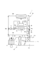
- FIG. 1 It is a schematic block diagram of the heating device for a vehicle which shows one Embodiment of this invention. It is a block diagram which shows the control system. It is a flowchart which shows the energization switching process.
- the vehicle heating device 1 of the present invention travels by utilizing the driving force of the engine as a driving source for traveling as the main driving force, and additionally adds the driving force of the electric motor to the driving force of the engine. It is applied to a so-called mild hybrid vehicle that can travel as a vehicle.
- the vehicle heating device 1 mainly cools the air conditioning unit 10 for supplying cooled or heated air to the vehicle interior of the vehicle and the engine, and is used during warm-up operation. It includes a cooling water circuit 20 as a heat medium circuit for circulating cooling water as a heat medium for heating the engine.
- the air conditioning unit 10 has an air flow passage 11 for circulating the air supplied to the vehicle interior.
- an outside air intake port 11a for allowing air outside the vehicle interior to flow into the air flow passage 11
- an inside air intake port 11b for allowing air inside the vehicle interior to flow into the air flow passage 11 Is provided.
- a foot outlet for blowing out the air flowing through the air flow passage 11 toward the feet of the passenger, and a vent (not shown) for blowing out toward the upper body of the passenger.
- An air outlet and a differential air outlet (not shown) that blows air toward the vehicle interior side surface of the windshield of the vehicle are provided.
- An indoor blower 12 such as a sirocco fan for circulating air from one end side to the other end side of the air flow passage 11 is provided on one end side in the air flow passage 11.
- a suction port switching damper 13 capable of opening one of the outside air suction port 11a and the inside air suction port 11b and closing the other is provided.
- the suction port switching damper 13 has an outside air supply mode in which the inside air suction port 11b is closed and the outside air suction port 11a is opened, an inside air circulation mode in which the outside air suction port 11a is closed and the inside air suction port 11b is opened, and an outside air suction port.
- a heat absorber 14 for cooling and dehumidifying the air flowing through the air flow passage 11 is provided on the downstream side of the indoor blower 12 in the air flow passage 11 in the air flow direction. Further, the downstream side of the heat absorber 14 in the air flow passage 11 in the air flow direction is partitioned by a partition wall 11c in a direction orthogonal to the extending direction of the air flow passage 11, so that the heated air flow passage 11d and the heated air flow flow. A bypass flow passage 11e that bypasses the road 11d is formed. The heated air flow passage 11d is provided with a heater core 15 as a heat exchanger for heating the air flowing through the heated air flow passage 11d.
- the heat absorber 14 exchanges heat between the air flowing through the air flow passage 11 and a refrigerant such as HFO-1234yf.
- a compressor (not shown), a radiator, an expansion valve, and the like, which are devices constituting the refrigeration cycle, are connected to the heat absorber 14.
- the air flowing through the air flow passage 11 is cooled by exchanging heat with the refrigerant that evaporates in the heat absorber 14.
- An air mix damper 17 for adjusting the ratio of the air heated by the heater core 15 to the air passing through the heat absorber 14 is provided between the heat absorber 14 and the heater core 15 in the air flow passage 11. ..
- the air mix damper 17 closes one of the heated air flow passage 11d and the bypass flow passage 11e upstream in the air flow direction and opens the other on the upstream side of the heated air flow passage 11d and the bypass flow passage 11e in the air flow direction.
- both the heated air flow passage 11d and the bypass flow passage 11e are opened to adjust the opening degree on the upstream side of the heated air flow passage 11d.
- the opening degree of the air mix damper 17 becomes 0% in a state where the upstream side of the heated air flow passage 11d is closed and the bypass flow passage 11d is opened, the upstream side of the heated air flow passage 11d is opened, and the bypass flow passage 11e is opened.
- the opening becomes 100% in the closed state.
- the cooling water circuit 20 includes the heater core 15, a pump 21 for pumping cooling water, a radiator 22 for radiating cooling water into the air outside the vehicle interior, a water jacket of engine E, and a flow direction of cooling water of engine E.
- the upstream side cooling water heating heater 23 as the upstream side heat medium heating unit for heating the cooling water flowing on the upstream side of the engine E, and the downstream side heat medium heating for heating the cooling water flowing on the downstream side of the engine E.
- the heater core side flow rate adjusting valve 25 for adjusting the flow rate of the cooling water flowing toward the heater core 15, and the cooling water flowing toward the radiator 22.
- the radiator side flow control valve 26 is provided, and these are connected by, for example, an aluminum pipe or a copper pipe.
- a coolant (LLC) containing ethylene glycol as a main component is used as the cooling water flowing through the cooling water circuit 20.
- the radiator 22 is arranged outside the vehicle interior such as the engine room so that the flow direction of the air that exchanges heat with the cooling water is the front-rear direction of the vehicle.
- an outdoor blower 22a for circulating air outside the vehicle interior in the front-rear direction when the vehicle is stopped is provided.
- the upstream cooling water heater 23 and the downstream cooling water heating heater 24 are electric heaters that generate heat by using the electric power of the battery B, respectively.
- the upstream cooling water heater 23 and the downstream cooling water heater 24 are connected to the battery B via dedicated power supply lines 23a and 24a, respectively, and the drive state is switched by on / off control.
- the battery B is, for example, a 48 V battery for supplying electric power to an electric motor (not shown) that applies a driving force to the driving force of the engine E.
- the cooling water inflow side of the water jacket of the engine E is connected to the cooling water discharge side of the pump 21 via the upstream cooling water heater 23. Further, on the cooling water outflow side of the engine E, the cooling water inflow side of the heater core 15 and the cooling water inflow side of the radiator 22 are connected in parallel to each other via a branch portion 20a that branches into the heater core 15 side and the radiator 22 side. ing. Between the branch portion 20a and the heater core 15, a heater core side flow rate adjusting valve 25 and a downstream side cooling water heating heater 24 are provided in this order from the branch portion 20a side. Further, a radiator-side flow rate adjusting valve 26 is provided between the branch portion 20a and the radiator 22.
- the cooling water suction side of the pump 21 is connected to the cooling water outflow side of the heater core 15 and the cooling water outflow side of the radiator 22 via the confluence portion 20b.
- the flow path of the cooling water from the branch portion 20a through the heater core 15 to the confluence portion 20b is the heating flow path 20c.
- the flow path of the cooling water from the branch portion 20a to the merging portion 20b through the radiator 22 is a bypass flow path 20d bypassing the heater core 15.
- the vehicle heating device 1 includes a controller 30 as a control unit for controlling the temperature and humidity in the vehicle interior to a set temperature and humidity and adjusting the temperature of the engine E.
- the controller 30 has a CPU, a ROM, and a RAM.
- the CPU reads the program stored in the ROM based on the input signal and stores the state detected by the input signal in the RAM. , Send an output signal to a device connected to the output side.
- the vehicle interior temperature sensor 31 for detecting the temperature inside the vehicle interior
- the outside air temperature sensor 32 for detecting the temperature outside the vehicle interior
- the amount of solar radiation are detected.
- the solar radiation amount sensor 33 for setting the temperature of the vehicle interior
- the vehicle interior temperature setting unit 34 for setting the target temperature in the vehicle interior
- the cooling water temperature sensor 35 for detecting the temperature of the cooling water in the cooling water circuit 20, and the engine E.
- Mode setting input unit for the user to input the operation to set the warm-up priority mode that prioritizes the warm-up operation or the heating priority mode that prioritizes the heating operation when the warm-up operation and the heating operation of the passenger compartment are performed at the same time. 36 and are connected.
- the upstream cooling water heating heater 23, the downstream cooling water heating heater 24, the heater core side flow rate adjusting valve 25, and the radiator side flow rate adjusting valve 26 are connected to the output side of the controller 30.
- the temperature of the engine E is adjusted by the cooling water flowing through the cooling water circuit 20. Further, the temperature of the space inside the vehicle interior is lowered by supplying the air cooled by the heat absorber 14 of the air conditioning unit 10 to the vehicle interior, and the temperature is raised by supplying the air heated by the heater core 15 to the vehicle interior. .. Further, the humidity of the space inside the vehicle interior is adjusted by cooling the air inside the vehicle interior with the heat absorber 14, reheating the air cooled by the heat absorber 14 with the heater core 15 and supplying it to the vehicle interior.
- the vehicle heating device 1 is used for warm-up operation for raising the temperature of the engine E when a vehicle parked for a long time starts running in a low temperature environment such as winter. At the same time, a heating operation is performed to raise the temperature of the space inside the vehicle.
- the valve opening degree of the flow rate adjusting valve 26 on the radiator side is reduced as compared with the case where the warm-up operation of the engine E is completed.
- the valve opening degree of the heater core side flow rate adjusting valve 25 is increased as compared with the case where the temperature inside the vehicle interior reaches the target temperature. That is, the controller 30 adjusts the valve opening degrees of the heater core side flow rate adjusting valve 25 and the radiator side flow rate adjusting valve 26 so that the flow rate of the cooling water flowing through the heater core 15 is larger than that of the radiator 22.
- the cooling water flowing through the cooling water circuit 20 is heated by at least one of the upstream cooling water heating heater 23 and the downstream cooling water heating heater 24, and flows through the heater core 15.
- the temperature inside the vehicle is promptly adjusted because the air heated by the cooling water heated by at least one of the upstream cooling water heating heater 23 and the downstream cooling water heating heater 24 is supplied to the vehicle interior. It rises to the target temperature.
- valve opening degree of the radiator side flow rate adjusting valve 26 may be fully closed and the valve opening degree of the heater core side flow rate adjusting valve 25 may be fully opened.
- all the cooling water heated by at least one of the upstream cooling water heating heater 23 and the downstream cooling water heating heater 24 flows through the heater core 15, so that the temperature inside the vehicle interior can be set to the target temperature more quickly. Raise to.
- controller 30 performs an energization switching process for switching the energization state of the upstream cooling water heating heater 23 and the downstream cooling water heating heater 24 when the warm-up operation and the heating operation are performed at the same time.
- the operation of the controller 30 at this time will be described with reference to the flowchart of FIG.
- Step S1 the CPU determines whether or not to perform the warm-up operation and the heating operation at the same time. If it is determined that the warm-up operation and the heating operation are performed at the same time, the process is moved to step S2, and if it is not determined that the warm-up operation and the heating operation are performed at the same time, the drive switching process is terminated.
- Step S2 When it is determined in step S1 that the warm-up operation and the heating operation are performed at the same time, the CPU calculates the heater required heating amount Cr in step S2 and shifts the process to step S3.
- the heater required heating amount Cr is the heating amount required for warming up, which is the heating amount required to complete the warming up operation, and the heating amount required to raise the temperature inside the vehicle interior to a target temperature by the heating operation. It is the sum of the required heating amount and the heating amount.
- the required heating amount for warming up and the required heating amount for heating are the heater required heating amount Cr, the detection temperature of the vehicle interior temperature sensor 31, the detection temperature of the outside air temperature sensor 32, the detection solar radiation amount of the solar radiation amount sensor 33, and the vehicle interior temperature setting unit. It is calculated based on the target temperature set in 34 and the detection temperature of the cooling water temperature sensor 35.
- step S3 the CPU determines whether or not the heater required heating amount Cr calculated in step S2 is equal to or greater than the predetermined heat amount C1. If it is determined that the heater required heating amount Cr is a predetermined heat amount C1 or more, the process is transferred to step S4, and if it is not determined that the heater required heating amount Cr is a predetermined heat amount C1 or more, the processing is transferred to step S5.
- the predetermined calorific value C1 is a calorific value that serves as a reference for simultaneously energizing the upstream cooling water heating heater 23 and the downstream cooling water heating heater 24. That is, the predetermined amount of heat C1 is when the amount of heat required to heat the cooling water of the cooling water circuit 20 is insufficient due to energization of one of the upstream cooling water heating heater 23 and the downstream cooling water heating heater 24. This is a reference amount of heat for simultaneously energizing the upstream cooling water heating heater 23 and the downstream cooling water heating heater 24.
- the predetermined amount of heat C1 is set to 1200 W, for example, when the electric capacities of the upstream cooling water heating heater 23 and the downstream cooling water heating heater 24 are 600 W, respectively.
- Step S4 When it is determined in step S3 that the required heating amount Cr of the heater is equal to or greater than the predetermined heat amount C1, in step S4, the CPU simultaneously drives the upstream cooling water heating heater 23 and the downstream cooling water heating heater 24 to perform the drive switching process. finish.
- the engine E is heated by the cooling water heated by the upstream cooling water heating heater 23 flowing through the water jacket, and the air supplied to the vehicle interior is the downstream cooling water heating heater 24 flowing through the heater core 15. It is heated with the cooling water heated by.
- Step S5 If it is not determined in step S3 that the heater required heating amount Cr is equal to or greater than the predetermined heat amount C1, the CPU determines in step S5 whether or not the heating priority mode is set in the mode setting input unit 36. If it is determined that the heating priority mode is set, the process is transferred to step S6, and if it is not determined that the heating priority mode is set, the process is transferred to step S7.
- Step S6 When it is determined in step S5 that the heating priority mode is set, in step S6, the CPU drives only the downstream cooling water heating heater 24 without driving the upstream cooling water heating heater 23 to switch the drive. End the process.
- the cooling water circuit 20 is heated by the downstream cooling water heating heater 24 by driving the downstream cooling water heating heater 24 without driving the upstream cooling water heating heater 23.
- the cooling water in a high temperature state flows into the heater core 15. Therefore, in the heating priority mode, it is possible to improve the heating capacity of the heating operation. Further, in the heating priority mode, the cooling water radiated from the heater core 15 flows into the water jacket of the engine E, so that the heating capacity of the warm-up operation is reduced.
- Step S7 When it is not determined in step S5 that the heating priority mode is set, in step S7, the CPU drives only the upstream cooling water heating heater 23 without driving the downstream cooling water heating heater 24. The drive switching process ends.
- the case where it is not determined that the heating priority mode is set indicates that the warm-up priority mode is set in the mode setting input unit 36.
- the warm-up priority mode by driving only the upstream cooling water heating heater 23 without driving the downstream cooling water heating heater 24, immediately after being heated by the upstream cooling water heating heater 23 in the cooling water circuit 20.
- the cooling water in the high temperature state flows into the water jacket of the engine E. Therefore, in the warm-up priority mode, it is possible to improve the heating capacity of the warm-up operation. Further, in the warm-up priority mode, the cooling water radiated by the engine E flows into the heater core 15, so that the heating capacity of the heating operation is lowered.
- the cooling water circuit 20 in which the engine E and the heater core 15 are connected in series with each other and the upstream side of the cooling water circuit 20 in the cooling water flow direction of the engine E are connected.
- the engine E is heated by the cooling water heated by the upstream cooling water heating heater 23 in the warm-up operation, and is supplied to the vehicle interior by the cooling water heated by the downstream cooling water heating heater 24 in the heating operation. Since the air can be heated, the warm-up operation can be completed quickly, and the temperature inside the vehicle interior can be quickly raised to a target temperature in the heating operation.
- the heater required heating amount Cr which is the total heating amount of the heating amount required in the warm-up operation and the heating amount required in the heating operation, is acquired, and upstream cooling is performed based on the acquired heater required heating amount Cr.
- a controller 30 for switching one or both of the water heater 23 and the downstream cooling water heater 24 to energize is provided.
- the controller 30 drives one of the upstream cooling water heater 23 and the downstream cooling water heating heater 24, the controller 30 has a heating priority mode for driving the downstream cooling water heating heater 24 and an upstream cooling water heating heater. It has a warm-up priority mode for energizing 23.
- downstream cooling water heater 24 is arranged between the branch portion 20a in the cooling water circuit 20 and the heater core 15.
- the cooling water heated by the downstream cooling water heating heater 24 flows into the heater core 15 without flowing to the radiator 22 side, so that most of the heat of the downstream cooling water heating heater 24 is transferred to the vehicle. It can be used for indoor heating and can improve energy efficiency.
- upstream cooling water heating heater 23 and the downstream cooling water heating heater 24 are connected to the battery B by dedicated power supply lines 23a and 24a, respectively.
- the outer diameters of the power supply lines 23a and 24a can be made smaller than those of the common power supply line, and the power supply line can be easily routed in the vehicle.
- the present invention is applied to a mild hybrid vehicle, but the present invention is not limited to this.
- the present invention it is also possible to apply the present invention to a vehicle that is driven only by an engine and that uses the heat of the cooling water that cools the engine to heat the interior of the vehicle.
- the engine E is shown as a drive source for performing warm-up operation, but the present invention is not limited to this.
- the present invention can be applied to, for example, a vehicle whose drive source is an electric motor whose efficiency is affected by the viscosity of the lubricating oil, as long as it is a drive source whose efficiency deteriorates in a low temperature environment.
- one upstream cooling water heating heater 23 is provided on the upstream side in the cooling water flow direction of the engine E, and one downstream cooling water heating heater 23 is provided on the downstream side in the cooling water flow direction of the engine E.
- the present invention is not limited to this.
- two or more upstream cooling water heaters are provided on the upstream side of the engine E in the cooling water flow direction, and / or two or more downstream cooling water heaters are provided on the downstream side of the engine cooling water flow direction. May be provided. In this case, it is possible to improve the control performance by controlling the on / off of a plurality of heaters on the upstream side and the downstream side of the engine according to the required heating amount.
- the heating amount can be adjusted by turning on / off each of the plurality of heaters, which is a simple control, a complicated control logic is not required. Further, in this case, the size of each heater can be reduced, so that the degree of freedom of layout in the vehicle can be improved.
- Vehicle heating device 15 Heater core 20 Cooling water circuit 20a Branch 20d Bypass flow path 22 Radiator 23 Upstream cooling water heating heater 24 Downstream cooling water heating heater 30 Controller B Battery E engine
Landscapes
- Engineering & Computer Science (AREA)
- Mechanical Engineering (AREA)
- Transportation (AREA)
- Chemical & Material Sciences (AREA)
- Combustion & Propulsion (AREA)
- Power Engineering (AREA)
- General Engineering & Computer Science (AREA)
- Automation & Control Theory (AREA)
- Physics & Mathematics (AREA)
- Thermal Sciences (AREA)
- Air-Conditioning For Vehicles (AREA)
- Electric Propulsion And Braking For Vehicles (AREA)
- Hybrid Electric Vehicles (AREA)
Abstract
【課題】駆動源の暖機運転を速やかに完了させるとともに、車室内の温度を速やかに目的の温度まで昇温させることのできる車両用加熱装置を提供する。 【解決手段】エンジンEとヒータコア15が互いに直列接続された冷却水回路20と、冷却水回路20におけるエンジンEの冷却水の流通方向の上流側を流通する冷却水を加熱する上流側冷却水加熱ヒータ23と、冷却水回路20におけるエンジンEの冷却水の流通方向の下流側を流通する冷却水を加熱する下流側冷却水加熱ヒータ24と、を備えている。
Description
本発明は、エンジン等の走行用の駆動源を備えた車両に適用される車両用加熱装置に関するものである。
従来、この種の車両用加熱装置としては、エンジン等の車両走行用の駆動源と車室内に供給する空気を加熱するための熱交換器とが互いに直列接続され、駆動源及び熱交換器において熱交換する熱媒体を流通させる熱媒体回路と、熱媒体回路を流通する熱媒体を加熱する熱媒体加熱部と、を備えたものが知られている(例えば、特許文献1参照)。
車両は、冬期等、気温の低い環境下において走行を開始する場合に、駆動源の暖機運転と車室内を昇温させる暖房運転とが同時に必要となる場合がある。このため、前記車両用加熱装置は、熱媒体回路を流通する熱媒体を熱媒体加熱部によって加熱することにより、熱媒体によって駆動源を加熱する暖機運転を行うと同時に、熱交換器において熱媒体によって車室内に供給する空気を加熱する暖房運転を行うことが可能となっている。
前記車両用加熱装置は、熱媒体回路の熱媒体の流通方向において、駆動源が熱交換器の上流側に配置され、熱媒体加熱部が駆動源の上流側に配置されている。このため、前記車両用加熱装置は、暖機運転と暖房運転とを同時に行う場合に、熱媒体加熱部において加熱された熱媒体が、駆動源において放熱した後、熱交換器において車室内に供給される空気と熱交換することになり、車室内に供給する空気を加熱する熱量が不足し、車室内を目的の温度まで昇温させるために長時間を要する可能性がある。
本発明の目的とするところは、駆動源の暖機運転を速やかに完了させるとともに、車室内の温度を速やかに目的の温度まで昇温させることのできる車両用加熱装置を提供することにある。
本発明の車両用加熱装置は、前記目的を達成するために、車両の走行用の駆動源と、車室内に供給する空気を加熱する熱交換器と、が互いに直列接続され、前記駆動源の暖機運転及び前記熱交換器を用いた暖房運転に利用可能な熱媒体が流通する熱媒体回路と、前記熱媒体回路における前記駆動源の熱媒体の流通方向の上流側を流通する熱媒体を加熱する上流側熱媒体加熱部と、前記熱媒体回路における前記駆動源の熱媒体の流通方向の下流側を流通する熱媒体を加熱する下流側熱媒体加熱部と、を備えている。
また、本発明の車両用加熱装置は、前記暖機運転において要求される加熱量と前記暖房運転において要求される加熱量とを合わせた加熱量である要求加熱量を取得し、取得した前記要求加熱量に基づいて前記上流側熱媒体加熱部及び下流側熱媒体加熱部の一方または両方を切り替えて通電させる制御部を備えている。
また、本発明の車両用加熱装置は、前記制御部が、前記上流側熱媒体加熱部及び下流側熱媒体加熱部の一方を通電させる場合において、前記下流側熱媒体加熱部を通電させる暖房優先モードと、前記上流側熱媒体加熱部を駆動させる暖機優先モードと、を有している。
また、本発明の車両用加熱装置は、前記熱媒体回路が、前記駆動源の熱媒体の流通方向の下流側に設けられた分岐部において分岐し、前記熱交換器を迂回して前記駆動源の熱媒体の流通方向の上流側に接続されるバイパス流路と、前記バイパス流路を流通する熱媒体を放熱させる放熱器と、を有し、前記下流側熱媒体加熱部は、前記熱媒体回路における前記分岐部と前記熱交換器との間に配置されている。
また、本発明の車両用加熱装置は、前記上流側熱媒体加熱部及び前記下流側熱媒体加熱部が、それぞれバッテリの電力を利用して熱を発生させる電気ヒータであり、前記バッテリに対してそれぞれ専用の電源ラインによって接続されている。
本発明によれば、暖機運転において上流側熱媒体加熱部により加熱された熱媒体によって駆動源を加熱するとともに、暖房運転において下流側熱媒体加熱部によって加熱された熱媒体によって車室内に供給する空気を加熱することができるので、暖機運転を速やかに完了させるとともに、暖房運転において車室内を速やかに目的の温度まで昇温させることが可能となる。
図1乃至図3は、本発明の一実施形態を示すものである。
本発明の車両用加熱装置1は、走行用の駆動源としてのエンジンの駆動力を主な駆動力として利用して走行し、エンジンの駆動力に対して補助的に電動モータの駆動力を付加して走行することが可能な、所謂マイルドハイブリッド車両に適用されるものである。
この車両用加熱装置1は、図1に示すように、冷却または加熱した空気を車両の車室内に供給するための空調ユニット10と、主にエンジンを冷却するものであって、暖機運転時にエンジンを加熱するための熱媒体としての冷却水を流通させるための熱媒体回路としての冷却水回路20と、を備えている。
空調ユニット10は、車室内に供給する空気を流通させるための空気流通路11を有している。空気流通路11の一端側には、車室外の空気を空気流通路11に流入させるための外気吸入口11aと、車室内の空気を空気流通路11に流入させるための内気吸入口11bと、が設けられている。また、空気流通路11の他端側には、空気流通路11を流通した空気を、搭乗者の足元に向かって吹き出させる図示しないフット吹出口、搭乗者の上半身に向かって吹き出させる図示しないベント吹出口、及び、車両のフロントガラスの車室内側の面に向かって吹き出させる図示しないデフ吹出口、が設けられている。
空気流通路11内の一端側には、空気流通路11の一端側から他端側に向かって空気を流通させるためのシロッコファン等の室内送風機12が設けられている。
空気流通路11の一端側には、外気吸入口11a及び内気吸入口11bの一方を開放して他方を閉鎖することが可能な吸入口切替ダンパ13が設けられている。吸入口切替ダンパ13は、内気吸入口11bを閉鎖して外気吸入口11aを開放する外気供給モードと、外気吸入口11aを閉鎖して内気吸入口11bを開放する内気循環モードと、外気吸入口11aと内気吸入口11bとの間に位置させることで外気吸入口11aと内気吸入口11bとをそれぞれ開放する内外気吸入モードと、を切り替えることが可能である。
空気流通路11における室内送風機12の空気流通方向下流側には、空気流通路11を流通する空気を冷却及び除湿するための吸熱器14が設けられている。また、空気流通路11における吸熱器14の空気流通方向下流側は、仕切壁11cによって空気流通路11の延びる方向に対して直交する方向に仕切ることにより、加熱空気流通路11dと、加熱空気流通路11dを迂回するバイパス流通路11eと、が形成されている。加熱空気流通路11dには、加熱空気流通路11dを流通する空気を加熱するための熱交換器としてのヒータコア15が設けられている。
吸熱器14は、空気流通路11を流通する空気と、例えば、HFO-1234yf等の冷媒と、を熱交換するものである。吸熱器14には、冷凍サイクルを構成する機器である、図示しない圧縮機、放熱器及び膨張弁等が接続されている。空気流通路11を流通する空気は、吸熱器14において蒸発する冷媒と熱交換することによって冷却される。
空気流通路11における吸熱器14とヒータコア15との間には、吸熱器14を通過した空気のうち、ヒータコア15によって加熱される空気の割合を調整するためのエアミックスダンパ17が設けられている。エアミックスダンパ17は、加熱空気流通路11d及びバイパス流通路11eの空気流通方向上流側において、加熱空気流通路11d及びバイパス流通路11eの一方の空気流通方向上流側を閉鎖して他方を開放したり、加熱空気流通路11d及びバイパス流通路11eの両方を開放し、加熱空気流通路11dの上流側の開度を調整したりする。エアミックスダンパ17は、加熱空気流通路11dの上流側を閉鎖してバイパス流通路11dを開放した状態で開度が0%となり、加熱空気流通路11dの上流側を開放し、バイパス流通路11eを閉鎖した状態で開度が100%となる。
冷却水回路20は、前記ヒータコア15、冷却水を圧送するためのポンプ21、冷却水を車室外の空気中に放熱するためのラジエータ22、エンジンEのウォータジャケット、エンジンEの冷却水の流通方向の上流側を流通する冷却水を加熱するための上流側熱媒体加熱部としての上流側冷却水加熱ヒータ23と、エンジンEの下流側を流通する冷却水を加熱するための下流側熱媒体加熱部としての下流側冷却水加熱ヒータ24と、ヒータコア15に向けて流通させる冷却水の流量を調整するためのヒータコア側流量調整弁25、ラジエータ22に向けて流通させる冷却水の流量を調整するためのラジエータ側流量調整弁26を有し、これらが例えばアルミニウム管や銅管によって接続されている。冷却水回路20を流通する冷却水としては、例えば、エチレングリコールを主成分とするクーラント(LLC)が用いられる。
ラジエータ22は、冷却水と熱交換する空気の流通方向が車両の前後方向となるように、エンジンルーム等の車室外に配置されている。ラジエータ22の近傍には、車両の停止時に車室外の空気を前後方向に流通させるための室外送風機22aが設けられている。
上流側冷却水加熱ヒータ23及び下流側冷却水加熱ヒータ24は、それぞれバッテリBの電力を利用して熱を発生させる電気ヒータである。上流側冷却水加熱ヒータ23及び下流側冷却水加熱ヒータ24は、それぞれ専用の電源ライン23a,24aを介してバッテリBに接続され、オン・オフ制御によって駆動状態が切り替えられる。バッテリBは、例えば、エンジンEの駆動力に対して駆動力を付加する図示しない電動モータに電力を供給するための48Vのバッテリである。
冷却水回路20の構成について具体的に説明すると、ポンプ21の冷却水吐出側には、上流側冷却水加熱ヒータ23を介してエンジンEのウォータジャケットの冷却水流入側が接続されている。また、エンジンEの冷却水流出側には、ヒータコア15側とラジエータ22側とに分岐する分岐部20aを介して、ヒータコア15の冷却水流入側及びラジエータ22の冷却水流入側が互いに並列に接続されている。分岐部20aとヒータコア15との間には、分岐部20a側から順に、ヒータコア側流量調整弁25、下流側冷却水加熱ヒータ24が設けられている。また、分岐部20aとラジエータ22との間には、ラジエータ側流量調整弁26が設けられている。ヒータコア15の冷却水流出側及びラジエータ22の冷却水流出側には、合流部20bを介してポンプ21の冷却水吸入側が接続されている。ここで、冷却水回路20において、分岐部20aからヒータコア15を通過して合流部20bに至る冷却水の流路は、暖房流路20cである。また、分岐部20aからラジエータ22を通過して合流部20bに至る冷却水の流路は、ヒータコア15を迂回するバイパス流路20dである。
また、この車両用加熱装置1は、車室内の温度及び湿度を設定された温度及び湿度にするとともに、エンジンEの温度を調整する制御を行うための制御部としてのコントローラ30を備えている。
コントローラ30は、CPU、ROM,RAMを有している。コントローラ30は、入力側に接続された装置からの入力信号を受信すると、CPUが、入力信号に基づいてROMに記憶されたプログラムを読み出すとともに、入力信号によって検出された状態をRAMに記憶したり、出力側に接続された装置に出力信号を送信したりする。
コントローラ30の入力側には、図2に示すように、車室内の温度を検出するための車室内温度センサ31と、車室外の温度を検出するための外気温度センサ32と、日射量を検出するための日射量センサ33と、車室内の目標温度を設定するための車室内温度設定部34と、冷却水回路20における冷却水の温度を検出するための冷却水温度センサ35と、エンジンEの暖機運転及び車室内の暖房運転を同時に行う場合において暖機運転を優先する暖機優先モードまたは暖房運転を優先する暖房優先モードを設定する操作を使用者が入力するためのモード設定入力部36と、が接続されている。
コントローラ30の出力側には、図2に示すように、上流側冷却水加熱ヒータ23、下流側冷却水加熱ヒータ24、ヒータコア側流量調整弁25及びラジエータ側流量調整弁26が接続されている。
以上のように構成された車両用加熱装置1において、エンジンEは、冷却水回路20を流通する冷却水によって温度が調整される。また、車室内の空間は、空調ユニット10の吸熱器14において冷却した空気を車室内に供給することで温度が低下し、ヒータコア15において加熱した空気を車室内に供給することで温度が上昇する。また、車室内の空間は、車室内の空気を吸熱器14において冷却し、吸熱器14において冷却した空気をヒータコア15において再加熱して車室内に供給することにより湿度が調整される。
また、車両用加熱装置1は、例えば冬期等、気温の低い環境下において長時間に渡って駐車している車両が走行を開始する場合に、エンジンEの温度を上昇させるための暖機運転と同時に、車室内の空間の温度を上昇させるための暖房運転を行う。
具体的には、コントローラ30は、暖機運転及び暖房運転を同時に行う場合に、エンジンEの暖機運転が完了している場合と比較してラジエータ側流量調整弁26の弁開度を小さくし、車室内の温度が目標の温度に到達している場合と比較してヒータコア側流量調整弁25の弁開度を大きくする。即ち、コントローラ30は、ラジエータ22よりもヒータコア15を流通する冷却水の流量が大きくなるように、ヒータコア側流量調整弁25及びラジエータ側流量調整弁26の弁開度を調整する。
これにより、冷却水回路20を流通する冷却水は、上流側冷却水加熱ヒータ23及び下流側冷却水加熱ヒータ24の少なくとも一方によって加熱されてヒータコア15を流通する。車室内の温度は、ヒータコア15において、上流側冷却水加熱ヒータ23及び下流側冷却水加熱ヒータ24の少なくとも一方で加熱された冷却水によって加熱された空気が車室内に供給されるため、速やかに目的の温度まで上昇する。
また、暖機運転及び暖房運転を同時に行う場合には、ラジエータ側流量調整弁26の弁開度を全閉とし、ヒータコア側流量調整弁25の弁開度を全開としてもよい。この場合には、上流側冷却水加熱ヒータ23及び下流側冷却水加熱ヒータ24の少なくとも一方によって加熱された全ての冷却水がヒータコア15を流通するため、より速やかに車室内の温度を目的の温度まで上昇させる。
また、コントローラ30は、暖機運転及び暖房運転を同時に行う場合に、上流側冷却水加熱ヒータ23及び下流側冷却水加熱ヒータ24の通電状態を切り替える通電切替処理を行う。このときのコントローラ30の動作を図3のフローチャートを用いて説明する。
(ステップS1)
ステップS1においてCPUは、暖機運転及び暖房運転を同時に行うか否かを判定する。暖機運転及び暖房運転を同時に行うと判定した場合にはステップS2に処理を移し、暖機運転及び暖房運転を同時に行うと判定しなかった場合には駆動切替処理を終了する。
ステップS1においてCPUは、暖機運転及び暖房運転を同時に行うか否かを判定する。暖機運転及び暖房運転を同時に行うと判定した場合にはステップS2に処理を移し、暖機運転及び暖房運転を同時に行うと判定しなかった場合には駆動切替処理を終了する。
(ステップS2)
ステップS1において暖機運転及び暖房運転を同時に行うと判定した場合に、ステップS2においてCPUは、ヒータ要求加熱量Crを算出してステップS3に処理を移す。
ステップS1において暖機運転及び暖房運転を同時に行うと判定した場合に、ステップS2においてCPUは、ヒータ要求加熱量Crを算出してステップS3に処理を移す。
ここで、ヒータ要求加熱量Crは、暖機運転を完了させるために必要な加熱量である暖機必要加熱量と、暖房運転によって車室内を目的の温度まで昇温させるために必要な加熱量である暖房必要加熱量と、を合算した加熱量である。暖機必要加熱量及び暖房必要加熱量は、ヒータ要求加熱量Crは、車室内温度センサ31の検出温度、外気温度センサ32の検出温度、日射量センサ33の検出日射量、車室内温度設定部34に設定された目標温度、冷却水温度センサ35の検出温度に基づいて算出される。
(ステップS3)
ステップS3においてCPUは、ステップS2において算出したヒータ要求加熱量Crが所定の熱量C1以上か否かを判定する。ヒータ要求加熱量Crが所定の熱量C1以上と判定した場合にはステップS4に処理を移し、ヒータ要求加熱量Crが所定の熱量C1以上と判定しなかった場合にはステップS5に処理を移す。
ステップS3においてCPUは、ステップS2において算出したヒータ要求加熱量Crが所定の熱量C1以上か否かを判定する。ヒータ要求加熱量Crが所定の熱量C1以上と判定した場合にはステップS4に処理を移し、ヒータ要求加熱量Crが所定の熱量C1以上と判定しなかった場合にはステップS5に処理を移す。
ここで、所定の熱量C1は、上流側冷却水加熱ヒータ23及び下流側冷却水加熱ヒータ24に対して同時に通電する基準となる熱量である。即ち、所定の熱量C1は、冷却水回路20の冷却水を加熱するために必要な熱量が、上流側冷却水加熱ヒータ23及び下流側冷却水加熱ヒータ24の一方に対する通電で不足する場合に、上流側冷却水加熱ヒータ23及び下流側冷却水加熱ヒータ24に対して同時に通電する基準となる熱量である。所定の熱量C1は、例えば、上流側冷却水加熱ヒータ23及び下流側冷却水加熱ヒータ24の電気容量がそれぞれ600Wの場合に、1200Wに設定される。
(ステップS4)
ステップS3においてヒータ要求加熱量Crが所定の熱量C1以上と判定した場合に、ステップS4においてCPUは、上流側冷却水加熱ヒータ23及び下流側冷却水加熱ヒータ24を同時に駆動させて駆動切替処理を終了する。
ステップS3においてヒータ要求加熱量Crが所定の熱量C1以上と判定した場合に、ステップS4においてCPUは、上流側冷却水加熱ヒータ23及び下流側冷却水加熱ヒータ24を同時に駆動させて駆動切替処理を終了する。
ここで、エンジンEは、ウォータジャケットを流通する上流側冷却水加熱ヒータ23によって加熱された冷却水で加熱され、車室内に供給される空気は、ヒータコア15を流通する下流側冷却水加熱ヒータ24によって加熱された冷却水で加熱される。
(ステップS5)
ステップS3においてヒータ要求加熱量Crが所定の熱量C1以上と判定しなかった場合に、ステップS5においてCPUは、モード設定入力部36において暖房優先モードが設定されているか否かを判定する。暖房優先モードが設定されていると判定した場合にはステップS6に処理を移し、暖房優先モードが設定されていると判定しなかった場合にはステップS7に処理を移す。
ステップS3においてヒータ要求加熱量Crが所定の熱量C1以上と判定しなかった場合に、ステップS5においてCPUは、モード設定入力部36において暖房優先モードが設定されているか否かを判定する。暖房優先モードが設定されていると判定した場合にはステップS6に処理を移し、暖房優先モードが設定されていると判定しなかった場合にはステップS7に処理を移す。
(ステップS6)
ステップS5において暖房優先モードが設定されていると判定した場合に、ステップS6においてCPUは、上流側冷却水加熱ヒータ23を駆動させることなく、下流側冷却水加熱ヒータ24のみを駆動させて駆動切替処理を終了する。
ステップS5において暖房優先モードが設定されていると判定した場合に、ステップS6においてCPUは、上流側冷却水加熱ヒータ23を駆動させることなく、下流側冷却水加熱ヒータ24のみを駆動させて駆動切替処理を終了する。
ここで、暖房優先モードは、上流側冷却水加熱ヒータ23を駆動させることなく、下流側冷却水加熱ヒータ24を駆動させることにより、冷却水回路20において下流側冷却水加熱ヒータ24によって加熱された直後の高温の状態の冷却水がヒータコア15に流入する。このため、暖房優先モードでは、暖房運転の加熱能力を向上させることが可能である。また、暖房優先モードでは、ヒータコア15において放熱した冷却水がエンジンEのウォータジャケットに流入することになるため、暖機運転の加熱能力が低下する。
(ステップS7)
ステップS5において暖房優先モードが設定されていると判定しなかった場合に、ステップS7においてCPUは、下流側冷却水加熱ヒータ24を駆動させることなく、上流側冷却水加熱ヒータ23のみを駆動させて駆動切替処理を終了する。
ステップS5において暖房優先モードが設定されていると判定しなかった場合に、ステップS7においてCPUは、下流側冷却水加熱ヒータ24を駆動させることなく、上流側冷却水加熱ヒータ23のみを駆動させて駆動切替処理を終了する。
ここで、暖房優先モードが設定されていると判定しなかった場合とは、モード設定入力部36において暖機優先モードが設定されている状態を示す。暖機優先モードは、下流側冷却水加熱ヒータ24を駆動させることなく、上流側冷却水加熱ヒータ23のみを駆動させることにより、冷却水回路20において上流側冷却水加熱ヒータ23によって加熱された直後の高温の状態の冷却水がエンジンEのウォータジャケットに流入する。このため、暖機優先モードでは、暖機運転の加熱能力を向上させることが可能である。また、暖機優先モードでは、エンジンEにおいて放熱した冷却水がヒータコア15に流入することになるため、暖房運転の加熱能力が低下する。
このように、本実施形態の車両用加熱装置によれば、エンジンEとヒータコア15が互いに直列接続された冷却水回路20と、冷却水回路20におけるエンジンEの冷却水の流通方向の上流側を流通する冷却水を加熱する上流側冷却水加熱ヒータ23と、冷却水回路20におけるエンジンEの冷却水の流通方向の下流側を流通する冷却水を加熱する下流側冷却水加熱ヒータ24と、を備えている。
これにより、暖機運転において上流側冷却水加熱ヒータ23により加熱された冷却水によってエンジンEを加熱するとともに、暖房運転において下流側冷却水加熱ヒータ24により加熱された冷却水によって車室内に供給する空気を加熱することができるので、暖機運転を速やかに完了させるとともに、暖房運転において車室内を速やかに目的の温度まで昇温させることが可能となる。
また、暖機運転において要求される加熱量と暖房運転において要求される加熱量とを合わせた加熱量であるヒータ要求加熱量Crを取得し、取得したヒータ要求加熱量Crに基づいて上流側冷却水加熱ヒータ23及び下流側冷却水加熱ヒータ24の一方または両方を切り替えて通電させるコントローラ30を備えている。
これにより、ヒータ要求加熱量Crに基づいて、上流側冷却水加熱ヒータ23及び下流側冷却水加熱ヒータ24の一方または両方の通電に切り替えることができるので、上流側冷却水加熱ヒータ23及び下流側冷却水加熱ヒータ24の一方のみの通電によって必要以上の電力を消費を抑制することができる。
また、コントローラ30は、上流側冷却水加熱ヒータ23及び下流側冷却水加熱ヒータ24の一方を駆動させる場合において、下流側冷却水加熱ヒータ24を駆動させる暖房優先モードと、上流側冷却水加熱ヒータ23を通電させる暖機優先モードと、を有している。
これにより、車両の使用者の要求に応じて暖房運転または暖機運転を優先させることが可能となるので、車両の使用者の快適性を向上させることが可能となる。
また、下流側冷却水加熱ヒータ24は、冷却水回路20における分岐部20aとヒータコア15との間に配置されている。
これにより、下流側冷却水加熱ヒータ24において加熱した冷却水が、ラジエータ22側に流通することなく、ヒータコア15に流入することになるため、下流側冷却水加熱ヒータ24の熱の大部分を車室内の暖房に利用することができ、エネルギー効率を向上させることが可能となる。
また、上流側冷却水加熱ヒータ23及び下流側冷却水加熱ヒータ24は、バッテリBに対してそれぞれ専用の電源ライン23a,24aによって接続されている。
これにより、共通の電源ラインと比較して電源ライン23a,24aのそれぞれの外径を小さくすることが可能となり、車両における電源ラインの取り回しが容易となる。
尚、前記実施形態では、マイルドハイブリッド車両に対して本発明を適用したものを示したが、これに限られるものではない。例えば、エンジンのみで駆動し、エンジンを冷却する冷却水の熱を利用して車室内の暖房運転を行う車両に対して本発明を適用することも可能である。
また、前記実施形態では、暖機運転を行う駆動源としてエンジンEを示したが、これに限られるものではない。気温の低い環境下において効率が悪化する駆動源であれば、例えば、潤滑油の粘度が効率に影響する電動モータを駆動源とする車両に対して本発明を適用することが可能である。
また、前記実施形態では、エンジンEの冷却水流通方向の上流側に一台の上流側冷却水加熱ヒータ23を設け、エンジンEの冷却水流通方向の下流側に一台の下流側冷却水加熱ヒータ24を設けたものを示したが、これに限られるものではない。例えば、エンジンEの冷却水流通方向の上流側に二台以上の上流側冷却水加熱ヒータを設け、および/または、エンジンの冷却水流通方向の下流側に二台以上の下流側冷却水加熱ヒータを設けてもよい。この場合、エンジンの上流側及び下流側のそれぞれにおいて複数のヒータを要求される加熱量に応じてオン・オフ制御することによって制御性能を向上させることが可能となる。また、この場合には、簡易な制御である、複数のヒータのそれぞれのオン・オフ制御によって加熱量を調節することができるので、複雑な制御ロジックを必要としない。さらに、この場合には、ヒータの一台当たりの大きさを小型化することが出来るため、車両におけるレイアウトの自由度を向上させることが可能となる。
1 車両用加熱装置
15 ヒータコア
20 冷却水回路
20a 分岐部
20d バイパス流路
22 ラジエータ
23 上流側冷却水加熱ヒータ
24 下流側冷却水加熱ヒータ
30 コントローラ
B バッテリ
E エンジン
15 ヒータコア
20 冷却水回路
20a 分岐部
20d バイパス流路
22 ラジエータ
23 上流側冷却水加熱ヒータ
24 下流側冷却水加熱ヒータ
30 コントローラ
B バッテリ
E エンジン
Claims (5)
- 車両の走行用の駆動源と、車室内に供給する空気を加熱する熱交換器と、が互いに直列接続され、前記駆動源の暖機運転及び前記熱交換器を用いた暖房運転に利用可能な熱媒体が流通する熱媒体回路と、
前記熱媒体回路における前記駆動源の熱媒体の流通方向の上流側を流通する熱媒体を加熱する上流側熱媒体加熱部と、
前記熱媒体回路における前記駆動源の熱媒体の流通方向の下流側を流通する熱媒体を加熱する下流側熱媒体加熱部と、を備えた
車両用加熱装置。 - 前記暖機運転において要求される加熱量と前記暖房運転において要求される加熱量とを合わせた加熱量である要求加熱量を取得し、取得した前記要求加熱量に基づいて前記上流側熱媒体加熱部及び下流側熱媒体加熱部の一方または両方を切り替えて通電させる制御部を備えた
請求項1に記載の車両用加熱装置。 - 前記制御部は、前記上流側熱媒体加熱部及び下流側熱媒体加熱部の一方を通電させる場合において、前記下流側熱媒体加熱部を通電させる暖房優先モードと、前記上流側熱媒体加熱部を通電させる暖機優先モードと、を有している
請求項2に記載の車両用加熱装置。 - 前記熱媒体回路は、前記駆動源の熱媒体の流通方向の下流側に設けられた分岐部において分岐し、前記熱交換器を迂回して前記駆動源の熱媒体の流通方向の上流側に接続されるバイパス流路と、前記バイパス流路を流通する熱媒体を放熱させる放熱器と、を有し、
前記下流側熱媒体加熱部は、前記熱媒体回路における前記分岐部と前記熱交換器との間に配置されている
請求項1乃至3のいずれかに記載の車両用加熱装置。 - 前記上流側熱媒体加熱部及び前記下流側熱媒体加熱部は、それぞれバッテリの電力を利用して熱を発生させる電気ヒータであり、前記バッテリに対してそれぞれ専用の電源ラインによって接続されている
請求項1乃至4のいずれかに記載の車両用加熱装置。
Applications Claiming Priority (2)
| Application Number | Priority Date | Filing Date | Title |
|---|---|---|---|
| JP2020064529A JP2021160574A (ja) | 2020-03-31 | 2020-03-31 | 車両用加熱装置 |
| JP2020-064529 | 2020-03-31 |
Publications (1)
| Publication Number | Publication Date |
|---|---|
| WO2021199775A1 true WO2021199775A1 (ja) | 2021-10-07 |
Family
ID=77928318
Family Applications (1)
| Application Number | Title | Priority Date | Filing Date |
|---|---|---|---|
| PCT/JP2021/006335 Ceased WO2021199775A1 (ja) | 2020-03-31 | 2021-02-19 | 車両用加熱装置 |
Country Status (2)
| Country | Link |
|---|---|
| JP (1) | JP2021160574A (ja) |
| WO (1) | WO2021199775A1 (ja) |
Citations (4)
| Publication number | Priority date | Publication date | Assignee | Title |
|---|---|---|---|---|
| JPH1178494A (ja) * | 1997-09-01 | 1999-03-23 | Toyota Autom Loom Works Ltd | 自動車用暖房装置 |
| WO2010079818A1 (ja) * | 2009-01-09 | 2010-07-15 | カルソニックカンセイ株式会社 | 車両用空調装置 |
| JP2014129054A (ja) * | 2012-12-28 | 2014-07-10 | Honda Motor Co Ltd | 車両用昇温装置 |
| WO2015040978A1 (ja) * | 2013-09-20 | 2015-03-26 | 三菱重工オートモーティブサーマルシステムズ株式会社 | 車両用空調装置、車両空調用ヒータ、及び車両の空調方法 |
Family Cites Families (6)
| Publication number | Priority date | Publication date | Assignee | Title |
|---|---|---|---|---|
| JP2006021730A (ja) * | 2004-07-09 | 2006-01-26 | Mitsubishi Heavy Ind Ltd | 車両用空調装置 |
| JP5407944B2 (ja) * | 2009-11-25 | 2014-02-05 | 株式会社デンソー | 車両用空調装置 |
| JP5382188B2 (ja) * | 2012-10-18 | 2014-01-08 | トヨタ自動車株式会社 | 車両の制御装置 |
| JP5761240B2 (ja) * | 2013-03-21 | 2015-08-12 | トヨタ自動車株式会社 | ハイブリッド自動車の制御装置 |
| JP6344305B2 (ja) * | 2015-05-18 | 2018-06-20 | 株式会社デンソー | 車両の空調制御装置 |
| WO2019022023A1 (ja) * | 2017-07-24 | 2019-01-31 | 株式会社デンソー | 冷却水回路 |
-
2020
- 2020-03-31 JP JP2020064529A patent/JP2021160574A/ja active Pending
-
2021
- 2021-02-19 WO PCT/JP2021/006335 patent/WO2021199775A1/ja not_active Ceased
Patent Citations (4)
| Publication number | Priority date | Publication date | Assignee | Title |
|---|---|---|---|---|
| JPH1178494A (ja) * | 1997-09-01 | 1999-03-23 | Toyota Autom Loom Works Ltd | 自動車用暖房装置 |
| WO2010079818A1 (ja) * | 2009-01-09 | 2010-07-15 | カルソニックカンセイ株式会社 | 車両用空調装置 |
| JP2014129054A (ja) * | 2012-12-28 | 2014-07-10 | Honda Motor Co Ltd | 車両用昇温装置 |
| WO2015040978A1 (ja) * | 2013-09-20 | 2015-03-26 | 三菱重工オートモーティブサーマルシステムズ株式会社 | 車両用空調装置、車両空調用ヒータ、及び車両の空調方法 |
Also Published As
| Publication number | Publication date |
|---|---|
| JP2021160574A (ja) | 2021-10-11 |
Similar Documents
| Publication | Publication Date | Title |
|---|---|---|
| CN110014840B (zh) | 电动机搭载车辆 | |
| JP2023182243A (ja) | 車両用空調装置の制御方法及び車両用空調装置 | |
| JP6992659B2 (ja) | 車両用熱管理装置 | |
| JP2020026197A (ja) | 車両用空気調和装置 | |
| KR101703667B1 (ko) | 차량용 공조장치 | |
| CN109715422B (zh) | 车用空调装置 | |
| JPH05229333A (ja) | 車両用ヒートポンプ式冷暖房装置 | |
| JP7783063B2 (ja) | 車両用空調装置 | |
| JP7165005B2 (ja) | 車両用空気調和装置 | |
| JP2019119356A (ja) | 車両用冷却装置 | |
| JP6900271B2 (ja) | 車両用空気調和装置 | |
| JP2019031109A (ja) | 車両用空調装置 | |
| WO2013114843A1 (ja) | 内燃機関温度調整システム | |
| WO2019230117A1 (ja) | 車両用空気調和装置 | |
| JP6831209B2 (ja) | 車両用空気調和装置 | |
| JP2022055722A (ja) | 制御装置および制御方法 | |
| JP7119698B2 (ja) | 車両用空調装置 | |
| CN110062708B (zh) | 车用空调装置 | |
| JP2023107644A (ja) | 車両用空調装置 | |
| JP5533808B2 (ja) | 車両用空調装置 | |
| JP2019098906A (ja) | 車両用廃熱利用装置 | |
| JP7387322B2 (ja) | 車両用空気調和装置 | |
| JP2021160574A (ja) | 車両用加熱装置 | |
| KR102615343B1 (ko) | 전기 자동차의 공조 시스템 및 그 제어 방법 | |
| JP2003136945A (ja) | 車両用空調装置 |
Legal Events
| Date | Code | Title | Description |
|---|---|---|---|
| 121 | Ep: the epo has been informed by wipo that ep was designated in this application |
Ref document number: 21779596 Country of ref document: EP Kind code of ref document: A1 |
|
| NENP | Non-entry into the national phase |
Ref country code: DE |
|
| 122 | Ep: pct application non-entry in european phase |
Ref document number: 21779596 Country of ref document: EP Kind code of ref document: A1 |