WO2021199294A1 - Information processing device, display method, and non-transitory computer-readable medium having program stored therein - Google Patents
Information processing device, display method, and non-transitory computer-readable medium having program stored therein Download PDFInfo
- Publication number
- WO2021199294A1 WO2021199294A1 PCT/JP2020/014850 JP2020014850W WO2021199294A1 WO 2021199294 A1 WO2021199294 A1 WO 2021199294A1 JP 2020014850 W JP2020014850 W JP 2020014850W WO 2021199294 A1 WO2021199294 A1 WO 2021199294A1
- Authority
- WO
- WIPO (PCT)
- Prior art keywords
- lesion
- image
- detected
- information processing
- control unit
- Prior art date
Links
- 230000010365 information processing Effects 0.000 title claims abstract description 87
- 238000000034 method Methods 0.000 title claims abstract description 60
- 230000003902 lesion Effects 0.000 claims abstract description 296
- 238000001514 detection method Methods 0.000 claims abstract description 118
- 230000008569 process Effects 0.000 claims abstract description 49
- 238000012545 processing Methods 0.000 claims description 23
- 238000010586 diagram Methods 0.000 description 13
- 238000003384 imaging method Methods 0.000 description 12
- 238000003780 insertion Methods 0.000 description 11
- 230000037431 insertion Effects 0.000 description 11
- 238000007689 inspection Methods 0.000 description 11
- 238000004590 computer program Methods 0.000 description 6
- 238000005286 illumination Methods 0.000 description 4
- 238000004891 communication Methods 0.000 description 3
- 238000013461 design Methods 0.000 description 3
- 201000010099 disease Diseases 0.000 description 3
- 208000037265 diseases, disorders, signs and symptoms Diseases 0.000 description 3
- 238000005401 electroluminescence Methods 0.000 description 3
- 230000006870 function Effects 0.000 description 3
- 206010028980 Neoplasm Diseases 0.000 description 2
- 239000002775 capsule Substances 0.000 description 2
- 239000004973 liquid crystal related substance Substances 0.000 description 2
- 238000010801 machine learning Methods 0.000 description 2
- 238000011897 real-time detection Methods 0.000 description 2
- 239000004065 semiconductor Substances 0.000 description 2
- 230000007704 transition Effects 0.000 description 2
- 208000037062 Polyps Diseases 0.000 description 1
- 230000005856 abnormality Effects 0.000 description 1
- 238000013528 artificial neural network Methods 0.000 description 1
- 201000011510 cancer Diseases 0.000 description 1
- 230000008859 change Effects 0.000 description 1
- 238000005352 clarification Methods 0.000 description 1
- 239000003086 colorant Substances 0.000 description 1
- 230000000295 complement effect Effects 0.000 description 1
- 238000013135 deep learning Methods 0.000 description 1
- 230000006866 deterioration Effects 0.000 description 1
- 238000003745 diagnosis Methods 0.000 description 1
- 210000001035 gastrointestinal tract Anatomy 0.000 description 1
- 238000001727 in vivo Methods 0.000 description 1
- 210000002429 large intestine Anatomy 0.000 description 1
- 230000036210 malignancy Effects 0.000 description 1
- 229910044991 metal oxide Inorganic materials 0.000 description 1
- 150000004706 metal oxides Chemical class 0.000 description 1
- 238000012986 modification Methods 0.000 description 1
- 230000004048 modification Effects 0.000 description 1
- 230000003287 optical effect Effects 0.000 description 1
- 239000013307 optical fiber Substances 0.000 description 1
- XLYOFNOQVPJJNP-UHFFFAOYSA-N water Substances O XLYOFNOQVPJJNP-UHFFFAOYSA-N 0.000 description 1
Images


Classifications
-
- A—HUMAN NECESSITIES
- A61—MEDICAL OR VETERINARY SCIENCE; HYGIENE
- A61B—DIAGNOSIS; SURGERY; IDENTIFICATION
- A61B1/00—Instruments for performing medical examinations of the interior of cavities or tubes of the body by visual or photographical inspection, e.g. endoscopes; Illuminating arrangements therefor
- A61B1/00002—Operational features of endoscopes
- A61B1/00004—Operational features of endoscopes characterised by electronic signal processing
- A61B1/00009—Operational features of endoscopes characterised by electronic signal processing of image signals during a use of endoscope
- A61B1/000094—Operational features of endoscopes characterised by electronic signal processing of image signals during a use of endoscope extracting biological structures
-
- A—HUMAN NECESSITIES
- A61—MEDICAL OR VETERINARY SCIENCE; HYGIENE
- A61B—DIAGNOSIS; SURGERY; IDENTIFICATION
- A61B1/00—Instruments for performing medical examinations of the interior of cavities or tubes of the body by visual or photographical inspection, e.g. endoscopes; Illuminating arrangements therefor
- A61B1/04—Instruments for performing medical examinations of the interior of cavities or tubes of the body by visual or photographical inspection, e.g. endoscopes; Illuminating arrangements therefor combined with photographic or television appliances
- A61B1/045—Control thereof
-
- A—HUMAN NECESSITIES
- A61—MEDICAL OR VETERINARY SCIENCE; HYGIENE
- A61B—DIAGNOSIS; SURGERY; IDENTIFICATION
- A61B1/00—Instruments for performing medical examinations of the interior of cavities or tubes of the body by visual or photographical inspection, e.g. endoscopes; Illuminating arrangements therefor
- A61B1/00002—Operational features of endoscopes
- A61B1/00043—Operational features of endoscopes provided with output arrangements
- A61B1/00045—Display arrangement
-
- A—HUMAN NECESSITIES
- A61—MEDICAL OR VETERINARY SCIENCE; HYGIENE
- A61B—DIAGNOSIS; SURGERY; IDENTIFICATION
- A61B1/00—Instruments for performing medical examinations of the interior of cavities or tubes of the body by visual or photographical inspection, e.g. endoscopes; Illuminating arrangements therefor
- A61B1/00002—Operational features of endoscopes
- A61B1/00043—Operational features of endoscopes provided with output arrangements
- A61B1/00055—Operational features of endoscopes provided with output arrangements for alerting the user
-
- A—HUMAN NECESSITIES
- A61—MEDICAL OR VETERINARY SCIENCE; HYGIENE
- A61B—DIAGNOSIS; SURGERY; IDENTIFICATION
- A61B1/00—Instruments for performing medical examinations of the interior of cavities or tubes of the body by visual or photographical inspection, e.g. endoscopes; Illuminating arrangements therefor
- A61B1/04—Instruments for performing medical examinations of the interior of cavities or tubes of the body by visual or photographical inspection, e.g. endoscopes; Illuminating arrangements therefor combined with photographic or television appliances
-
- A—HUMAN NECESSITIES
- A61—MEDICAL OR VETERINARY SCIENCE; HYGIENE
- A61B—DIAGNOSIS; SURGERY; IDENTIFICATION
- A61B1/00—Instruments for performing medical examinations of the interior of cavities or tubes of the body by visual or photographical inspection, e.g. endoscopes; Illuminating arrangements therefor
- A61B1/00002—Operational features of endoscopes
- A61B1/00004—Operational features of endoscopes characterised by electronic signal processing
- A61B1/00009—Operational features of endoscopes characterised by electronic signal processing of image signals during a use of endoscope
- A61B1/000096—Operational features of endoscopes characterised by electronic signal processing of image signals during a use of endoscope using artificial intelligence
-
- A—HUMAN NECESSITIES
- A61—MEDICAL OR VETERINARY SCIENCE; HYGIENE
- A61B—DIAGNOSIS; SURGERY; IDENTIFICATION
- A61B1/00—Instruments for performing medical examinations of the interior of cavities or tubes of the body by visual or photographical inspection, e.g. endoscopes; Illuminating arrangements therefor
- A61B1/00002—Operational features of endoscopes
- A61B1/00043—Operational features of endoscopes provided with output arrangements
- A61B1/00045—Display arrangement
- A61B1/0005—Display arrangement combining images e.g. side-by-side, superimposed or tiled
Definitions
- the present disclosure relates to an information processing device, a display method, and a non-temporary computer-readable medium in which a program is stored.
- Patent Document 1 discloses an image display device that displays an image taken by a capsule endoscope. This image display device displays a slider indicating the shooting time of the image currently displayed in the main image display area on the time bar indicating the imaging period of the capsule endoscope.
- Patent Document 1 does not assume that the user confirms the lesion detected by the detection process using an endoscope. Therefore, in the technique, the lesion detected by the detection process is not assumed. I can't figure out how far before the shooting time of.
- the present disclosure provides an information processing device, a display method, and a program that can easily grasp during an examination how far before the imaging time of a lesion detected by a detection process on an image captured by an endoscope is from the present.
- the purpose is to do.
- the information processing device is An image acquisition unit that sequentially acquires the images currently taken by the endoscope, and A lesion detection unit that sequentially performs a lesion site detection process on images sequentially acquired by the image acquisition unit, and a lesion detection unit. It has a display control unit that displays on a display device the degree of passage of time up to the current time point at the time of taking the image in which the lesion site is detected by the lesion detection unit.
- the program according to the third aspect of the present disclosure is An image acquisition step to sequentially acquire the images currently taken by the endoscope, and A lesion detection step in which lesion site detection processing is sequentially performed on sequentially acquired images, and At the time of taking the image in which the lesion site is detected, the computer is made to perform a display control step of displaying the degree of passage of time up to the present time on the display device.
- an information processing device a display method, and a program that can easily grasp during an examination how far before the imaging time of a lesion detected by a detection process on an image captured by an endoscope is from the present. can.
- FIG. It is a block diagram which shows an example of the structure of the information processing apparatus which concerns on Embodiment 1.
- FIG. It is a block diagram which shows the structure of the inspection support system which concerns on Embodiment 2.
- FIG. It is a schematic diagram which shows an example of the display screen generated by a processor apparatus. It is a block diagram which shows an example of the functional structure of the information processing apparatus which concerns on Embodiment 2.
- FIG. It is a schematic diagram which shows the display example based on the control of a display control unit.
- It is a schematic diagram which shows an example of the hardware configuration of the information processing apparatus which concerns on Embodiment 2.
- FIG. It is a flowchart which shows an example of the operation of the information processing apparatus during inspection by an endoscope.
- It is a schematic diagram which shows the display example based on the control of a display control unit.
- FIG. 1 is a block diagram showing an example of the configuration of the information processing apparatus 1 according to the first embodiment.
- the information processing device 1 is a device that supports an examination by a user (for example, a doctor) using an endoscope, and performs a lesion detection process using an image taken by the endoscope and a display process based on the detection result.
- the information processing device 1 includes an image acquisition unit 2, a lesion detection unit 3, and a display control unit 4.
- the image acquisition unit 2 sequentially acquires the images currently taken by the endoscope. Specifically, the image acquisition unit 2 sequentially acquires each frame image constituting the moving image taken by the endoscope.
- the lesion detection unit 3 sequentially performs a lesion site detection process on the images sequentially acquired by the image acquisition unit 2.
- the lesion detection unit 3 performs an arbitrary image recognition process to detect the lesion site captured in the image.
- the lesion refers to an abnormality in a living tissue caused by a disease or the like, and includes, but is not limited to, for example, a polyp or a tumor.
- the display control unit 4 controls the display of information on the display device. Specifically, the display control unit 4 displays on the display device the degree of passage of time up to the current time point at the time of taking an image in which the lesion site is detected by the lesion detection unit 3. This degree of progress can be said to be an index indicating how long ago the lesion was detected in the image taken from the present. Any display mode can be adopted as the display mode of the degree of progress. As will be described in the embodiment described later, the display control unit 4 may graphically display the degree of elapsed time, or may display a numerical value indicating the elapsed time up to the current time point.
- the display control unit 4 controls to display the degree of passage of time up to the current time point at the time of taking an image in which the lesion site is detected by the lesion detection unit 3. Therefore, the user can easily grasp when the lesion detected by the detection process was photographed during the examination. That is, according to the information processing device 1 or the display method realized by the above processing, it is being inspected how far before the imaging time of the lesion detected by the detection processing on the image captured by the endoscope is from the present. Can be easily grasped.
- the information processing device 1 includes a processor and a memory as a configuration (not shown).
- the processor reads a computer program in which the above-mentioned processing of the information processing apparatus 1 is implemented from the memory, and executes the computer program. As a result, the processor realizes the functions of the image acquisition unit 2, the lesion detection unit 3, and the display control unit 4.
- the image acquisition unit 2, the lesion detection unit 3, and the display control unit 4 may each be realized by dedicated hardware.
- a part or all of each component of each device may be realized by a general-purpose or dedicated circuitry, a processor, or a combination thereof. These may be composed of a single chip or may be composed of a plurality of chips connected via a bus.
- a part or all of each component of each device may be realized by a combination of the above-mentioned circuit or the like and a program.
- a processor a CPU (Central Processing Unit), a GPU (Graphics Processing Unit), or the like can be used as a processor.
- each component of the information processing device 1 when a part or all of each component of the information processing device 1 is realized by a plurality of information processing devices and circuits, the plurality of information processing devices and circuits may be centrally arranged. It may be distributed.
- the information processing device, the circuit, and the like may be realized as a form in which each of the client-server system, the cloud computing system, and the like is connected via a communication network.
- the function of the information processing device 1 may be provided in the SaaS (Software as a Service) format.
- FIG. 2 is a block diagram showing a configuration of the inspection support system 10 according to the second embodiment.
- the inspection support system 10 includes an endoscope system 100, an information processing device 200, a display device 300, and a speaker 400.
- the endoscopic system 100 is used to inspect the lumen in the living body of the subject to be inspected. For example, it is used to examine the large intestine, but it may also be used to examine other gastrointestinal tracts and the like.
- the endoscope system 100 includes an endoscope 110, a light source device 120, a processor device 130, and a display device 140.
- the endoscope 110 is optically connected to the light source device 120 and further electrically connected to the processor device 130.
- the endoscope 110 has an insertion unit 111 to be inserted into the body of a person to be inspected, and an operation unit 112 for operating the direction of the tip of the insertion unit 111.
- the endoscope 110 is provided with an imaging unit 113 for photographing the inside of the body.
- the image pickup unit 113 includes, for example, various lenses, an image pickup sensor, a signal processing circuit, and the like.
- As the image pickup sensor for example, a sensor such as a CCD (Charge Coupled Device) or a CMOS (Complementary Metal-Oxide Semiconductor) is used.
- the various lenses and the image sensor are arranged at the tip of the insertion unit 111, for example, and the other signal processing circuits are arranged at the operation unit 112, for example.
- the imaging unit 113 outputs an image signal of the captured image to the processor device 130 under the control of the processor device 130.
- the insertion portion 111 Inside the insertion portion 111, a light guide that propagates the illumination light from the light source device 120 to the tip of the insertion portion 111 is provided, and the inside of the body can be illuminated by the illumination light. Further, the insertion portion 111 is provided with a treatment tool insertion passage for guiding a treatment tool such as an electronic knife from the operation portion 112 to the tip of the insertion portion 111. Therefore, the user (doctor) can excise the lesion site or the like with the treatment tool while looking at the image taken by the endoscope 110. Further, the insertion portion 111 is provided with a nozzle for injecting air, water, or the like from the tip of the insertion portion 111.
- a treatment tool insertion passage for guiding a treatment tool such as an electronic knife from the operation portion 112 to the tip of the insertion portion 111. Therefore, the user (doctor) can excise the lesion site or the like with the treatment tool while looking at the image taken by the endoscope 110. Further
- the light source device 120 is a device that supplies illumination light to the above-mentioned light guide provided in the endoscope 110 under the control of the processor device 130.
- the illumination light output from the light source device 120 passes through the light guide and is emitted from the tip of the endoscope 110. As a result, the observation site in the body is irradiated.
- the processor device 130 is electrically connected to the endoscope 110, the light source device 120, the display device 140, and the information processing device 200.
- the processor device 130 comprehensively controls the operation of the endoscope system 100.
- the processor device 130 performs predetermined image processing on the image signal received from the endoscope 110 to generate a captured image to be displayed on the display device 140.
- the processor device 130 arranges the photographed image in the photographed image area 50, and arranges characters or images of various reference information such as information of the inspection target person in the non-photographed image area 51.
- Image 52 is generated.
- the display image 52 is an image displayed on the entire screen of the display device 140.
- the processor device 130 controls the display image 52 to be displayed on the display device 140.
- the processor device 130 outputs the display image 52 to the information processing device 200.
- the processor device 130 may output the captured image to the information processing device 200.
- the processor device 130 outputs the display image 52 or the captured image to the information processing device 200, so that the current captured image by the endoscope 110 is sequentially output to the information processing device 200.
- the processor device 130 outputs to the information processing device 200 in real time a moving image taken by the endoscope 110, that is, a series of images taken continuously in time of the lumen in the living body.
- the processor device 130 includes, for example, a memory and a processor such as a CPU and a GPU, and the processor reads software (computer program) including one or more instructions from the memory and executes it to realize the processing of the processor device 130. do.
- software computer program
- the display device 140 displays the display image 52 generated by the processor device 130.
- the display device 140 is a platform panel display such as a liquid crystal display, a plasma display, or an organic EL (Electro-Luminescence) display.
- the display device 300 is a device that is electrically connected to the information processing device 200 and displays an image under the control of the information processing device 200.
- the display device 300 is a platform panel display such as a liquid crystal display, a plasma display, or an organic EL display.
- the speaker 400 is electrically connected to the information processing device 200, and outputs sound under the control of the information processing device 200.
- the information processing device 200 corresponds to the information processing device 1 of FIG. 1 and is a device that supports the inspection of a user (for example, a doctor). The details of the information processing apparatus 200 will be described below.
- FIG. 4 is a block diagram showing an example of the functional configuration of the information processing device 200.
- the information processing apparatus 200 includes an image acquisition unit 210, a lesion detection unit 220, a sound control unit 230, and a display control unit 240.
- the image acquisition unit 210 corresponds to the image acquisition unit 2 in FIG. 1, and sequentially acquires the images currently captured by the endoscope 110. More specifically, the image acquisition unit 210 sequentially acquires a series of images in which the lumen in the living body is continuously photographed in real time. That is, the image acquisition unit 210 sequentially acquires each frame image (still image) constituting the captured moving image in real time. When the output from the processor device 130 is the display image 52, the image acquisition unit 210 performs a process of cutting out the captured image arranged in the captured image area 50 from the display image 52.
- the lesion detection unit 220 corresponds to the lesion detection unit 3 in FIG. 1, and sequentially performs a lesion site detection process on the images sequentially acquired by the image acquisition unit 210. That is, the lesion site is sequentially detected for each frame image constituting the captured moving image.
- the lesion detection unit 220 performs real-time detection processing of the lesion site. For example, it is preferable that the lesion detection unit 220 performs the detection process at a processing speed faster than the frame rate of the captured moving image.
- the lesion detection unit 220 performs a known image recognition process to detect the lesion site from the image. In this detection process, the position of the lesion site in the image is also detected.
- the lesion detection unit 220 performs a lesion site detection process by inputting an image acquired by the image acquisition unit 210 into a model learned in advance by a machine learning algorithm.
- This model is, for example, a model learned by deep learning such as CNN (Convolution Neural Network), but may be a model learned by using another machine learning algorithm.
- the lesion detection unit 220 displays the image based on whether or not the index value (accuracy) indicating the probability that the lesion site is captured in the image, which is output from the above-mentioned model, exceeds a predetermined threshold value. Determine if the lesion site is visible.
- an image including a lesion site that is, an image in which a lesion site is detected is also referred to as a lesion image.
- the lesion detection unit 220 detects the lesion site, the lesion image, the position information in the image of the detected lesion site in the image, the above-mentioned index value, and the time when the lesion image is taken are stored in a storage device such as a memory 291 described later.
- Information (hereinafter referred to as shooting time information) representing the image is stored.
- the shooting time information may be any information that can identify how far the time when the shooting was performed is in the past from the current time.
- the shooting time information is the system time at the time when shooting is performed.
- the captured image is acquired by the image acquisition unit 210 in real time, and the lesion detection process is performed in real time.
- the lesion detection unit 220 may use the time when the information processing apparatus 200 acquires the image as the image acquisition time point information, or the lesion detection unit 220 may use the time when the lesion detection process is performed as the image acquisition time point information. May be.
- the shooting time information may be attached to the image data by the processor device 130 as incidental information. As described above, the shooting time information may be information that can identify how far the shooting time is from the current time, so the frame number of the moving image is used instead of the system time. May be good. This is because, which is the captured image in which the lesion was detected based on the frame number of the latest captured image (current captured image), the frame number of the past captured image in which the lesion was detected, and the frame rate of the moving image. This is because it is possible to identify whether the image was taken in the past.
- the sound control unit 230 controls the output of the speaker 400.
- the sound control unit 230 outputs a sound notifying the detection from the speaker 400. This makes it possible to notify the user of the detection of the lesion site. For example, a user who hears this sound can search for a lesion site detected by the information processing apparatus 200 by adjusting the imaging position of the endoscope 110.
- the display device 300 displays an index indicating how long before the present time the lesion site was detected in the image taken. Therefore, by confirming this, the user can easily grasp how much the position of the endoscope 110 should be returned from the current position. Therefore, by performing the display control described later, the user can easily adjust the position of the endoscope 110 in the living body so that the detected lesion is photographed again.
- the display control unit 240 controls the display of the display device 300.
- the display control unit 240 corresponds to the display control unit 4 of FIG. Therefore, in particular, the display control unit 240 displays on the display device 300 the degree of passage of time up to the current time point with respect to the time point of photographing the lesion image found by the processing of the lesion detection unit 220.
- the display control unit 240 specifies the degree of progress of the lesion image by referring to the information at the time of photographing the lesion image and calculating the elapsed time since the lesion image was photographed.
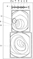
- FIG. 5 is a schematic view showing a display example of the display device 300 based on the control of the display control unit 240.
- the display control of the display control unit 240 of the present embodiment will be described with reference to FIG.
- the display control unit 240 displays the image 61 in which the lesion site is detected by the lesion detection unit 220 in the lesion image area 60 on the screen of the display device 300.
- the latest detected lesion image is displayed in the lesion image area 60.
- the display control unit 240 further displays the position of the lesion site detected by the lesion detection unit 220 in the image 61.
- the display control unit 240 displays the frame 62 surrounding the lesion site on the image 61.
- the display control unit 240 determines the display position of the frame 62 based on the position information of the lesion site output by the lesion detection unit 220. Since the display indicating the position of the lesion site is performed in this way, the user can easily confirm where the information processing apparatus 200 has detected as the lesion.
- the display control unit 240 displays the current captured image by the endoscope 110 sequentially acquired from the processor device 130 by the image acquisition unit 210 in the captured video area 63 on the screen of the display device 300.
- the lesion image in the lesion image region 60 and the image currently displayed by the endoscope 110 are displayed side by side on the display device 300.
- the display control unit 240 displays the degree of passage of time for the lesion image identified during the examination in the time passage area 64 on the screen of the display device 300.
- the display control unit 240 displays a mark 66 indicating the time of taking an image in which the lesion site is detected by the lesion detection unit 220 on the time axis 65 starting from the current time point. Display the degree of progress.
- the mark 66 is a circle mark, but a mark of another design may be used.
- One end 65a of the time axis 65 represents the current time point
- the other end 65b of the time axis 65 represents a time point that goes back by a predetermined period from the current time point.
- the time from the present to 5 seconds before is represented by the time axis 65, but the predetermined period is not limited to 5 seconds and any time can be set.
- each mark 66 represents the time when the lesion image was taken. As the time advances, the time point at which the lesion image is taken shifts to a point in the distant past. Therefore, the display control unit 240 moves the display position of the mark 66 on the time axis 65 with the transition of the time. In the example shown in FIG.
- the display control unit 240 displays the mark 66 so as to flow downward along the time axis 65 as the time advances.
- the mark 66 indicating the time of imaging of the lesion image is displayed on the time axis 65, the degree of passage of time at the time of imaging is graphically displayed. Therefore, the user can easily visually grasp the degree of passage of time when the lesion image is taken.
- the display control unit 240 is between the images sequentially acquired by the image acquisition unit 210 from the current time point to a time point preceding a predetermined period (5 seconds as an example in FIG. 5).
- the progress of the captured image is displayed. That is, the display control unit 240 does not display the degree of progress for all the lesions detected during the examination, but displays the degree of progress for the lesions detected in the latest period. If the degree of progress is displayed for the entire period from the start of the inspection to the present time, a large amount of information will be displayed on a limited screen size, and the visibility of the information will be reduced.
- the degree of progress only for the lesions detected in the latest period it is possible to easily display the degree of progress of the lesions detected in the latest period.
- the need for the user to confirm the lesion detected by the information processing apparatus 200 using the endoscope 110 that is, the need for adjusting the position of the endoscope 110 so that the lesion is photographed again is this lesion. Often occurs immediately after is detected. Therefore, it is possible to improve the convenience of the user by displaying the elapsed time only in the latest period.
- the display control unit 240 may display the degree of progress for the entire period from the start of the inspection to the present time.
- the display control unit 240 may display the mark 66 according to the accuracy of detection in the detection process. Specifically, the display control unit 240 displays the mark 66 according to the index value of the image determined to be the lesion image by the lesion detection unit 220. That is, the display control unit 240 may display the mark 66 having a different design depending on the index value. As described above, the index value represents the probability that the lesion site is captured in the image, and is output by the lesion detection unit 220. For example, the display control unit 240 may display the marks 66 of different colors according to the index value. The shape or pattern may be changed instead of the color. By doing so, the user can easily grasp the reliability of the detection result by the information processing apparatus 200.
- the display control unit 240 may change the display mode of the mark 66 depending on other factors, not limited to the accuracy of detection. For example, the display control unit 240 may display the mark 66 according to the size of the lesion site detected by the lesion detection unit 220 or the diagnosis result (whether benign or not, or the degree of malignancy, etc.).
- the display control unit 240 may display a mark 66 according to the number of detected lesion sites. That is, the display control unit 240 may display the mark 66 having a different design depending on the number of detected lesion sites. Further, the display control unit 240 may display the value of the number of detected lesion sites in the vicinity of the mark 66. By doing so, the user can easily grasp the number of detected lesion sites.
- FIG. 6 is a schematic diagram showing an example of the hardware configuration of the information processing apparatus 200.
- the information processing apparatus 200 includes an input / output interface 290, a memory 291 and a processor 292.
- the input / output interface 290 is an input / output circuit for communicating with any other device such as the processor device 130, the display device 300, and the speaker 400.
- the memory 291 is composed of, for example, a combination of a volatile memory and a non-volatile memory.
- the memory 291 is used to store software (computer program) including one or more instructions executed by the processor 292, data used for various processes of the information processing apparatus 200, and the like.
- the processor 292 reads software (computer program) from the memory 291 and executes it to process each component shown in FIG. Specifically, the processor 292 processes the image acquisition unit 210, the lesion detection unit 220, the sound control unit 230, and the display control unit 240.
- the processor 292 may be, for example, a CPU, a GPU, or the like. Processor 292 may include a plurality of processors. As described above, the information processing apparatus 200 has a function as a computer.
- Non-transitory computer-readable media include various types of tangible storage media (tangible storage media).
- Examples of non-temporary computer-readable media include magnetic recording media (eg, flexible disks, magnetic tapes, hard disk drives), magneto-optical recording media (eg, magneto-optical disks), CD-ROMs (Read Only Memory) CD-Rs, CDs. -R / W, including semiconductor memory (for example, mask ROM, PROM (Programmable ROM), EPROM (Erasable PROM), flash ROM, RAM (Random Access Memory)).
- the program may also be supplied to the computer by various types of temporary computer-readable media.
- Examples of temporary computer-readable media include electrical, optical, and electromagnetic waves.
- the temporary computer-readable medium can supply the program to the computer via a wired communication path such as an electric wire and an optical fiber, or a wireless communication path.
- FIG. 7 is a flowchart showing an example of the operation of the information processing apparatus 200 during the inspection by the endoscope 110.
- an operation example will be described with reference to the flowchart of FIG. 7.
- step S100 the image acquisition unit 210 acquires the current captured image by the endoscope 110 output from the processor device 130.
- step S101 the lesion detection unit 220 performs a lesion detection process on the image acquired in step S100.
- the process proceeds to step S103. If no lesion is detected in the image (No in step S102), the process proceeds to step S104.
- step S103 the sound control unit 230 outputs a sound notifying that the lesion has been detected from the speaker 400. After step S103, the process proceeds to step S104.
- step S104 the display control unit 240 calculates the elapsed time from the acquisition of the lesion image that has already been detected between the start of the examination and the present. As a result, the display control unit 240 specifies the degree of passage of time for the detected lesion image.
- step S105 the display control unit 240 determines the lesion image of the target to be displayed with the degree of progress from the lesion images already detected from the start of the examination to the present. Specifically, the display control unit 240 sets the lesion image whose elapsed time is within the range of the time axis 65 as the display target of the elapsed time. That is, the display control unit 240 sets the lesion image taken between the current time point and the previous time point by a predetermined period (5 seconds as an example in FIG. 5) as the display target of the degree of progress.
- step S106 the display control unit 240 determines the display content of the display device 300. Specifically, the display control unit 240 displays the latest detected lesion image in the lesion image area 60, and displays a frame 62 surrounding the lesion site on the lesion image. In addition, the display control unit 240 displays the currently captured image by the endoscope 110 in the captured image area 63. Then, the display control unit 240 displays the elapsed degree of the lesion image determined as the display target of the elapsed degree in step S105 in the time elapsed area 64. After step S106, the process returns to step S100, and the above-described process is performed on the next image.
- the display control unit 240 uses the time axis 65 and the mark 66 to determine the degree of passage of time from the time of taking the image in which the lesion site is detected by the lesion detection unit 220 to the current time point. indicate. Therefore, since the degree of progress is displayed graphically, the user can easily visually grasp when the lesion detected by the detection process of the information processing apparatus 200 was photographed during the examination. Can be done. That is, the user can easily visually grasp during the examination how far before the imaging time of the lesion detected by the detection process of the information processing apparatus 200 is from the present. Therefore, the user can easily guess how much the endoscope 110 should be moved in order to re-photograph the lesion with the endoscope 110.
- the display control unit 240 displays one lesion image in the lesion image area 60 on the screen of the display device 300, but a plurality of lesion images may be displayed.
- the points different from those of the second embodiment will be described, and the description of the overlapping configuration and processing will be omitted.
- the display control unit 240 displays the plurality of lesion images in the lesion image area 60 as shown in FIG. ..
- the display control unit 240 may set an upper limit on the number of lesion images to be displayed. For example, the display control unit 240 may display a maximum of N (where N is a positive integer) lesion images detected most recently. When the value of N is 1, one lesion image is displayed as in the second embodiment.
- the display control unit 240 may display a line 67 that associates the position in the image of the lesion site detected by the lesion detection unit 220 with the mark 66. By doing so, the degree of progress of each lesion image can be easily determined.
- the line 67 that associates the position of the lesion site in the image with the mark 66 may be displayed regardless of the number of displayed lesion images. That is, the line 67 may be displayed even when only one lesion image is displayed. Further, when a plurality of lesion sites are detected in one lesion image, a line 67 may be displayed for each lesion site.
- the fourth embodiment will be described.
- the lesion detection unit 220 detects the same lesion site in a plurality of images
- the degree of progress can be displayed for each image. Therefore, the visibility of the degree of progress may decrease. Therefore, in the present embodiment, the degree of progress is not displayed for each image for the same lesion site.
- the information processing device 200 is replaced by the information processing device 500.
- FIG. 9 is a block diagram showing an example of the functional configuration of the information processing apparatus 500 according to the fourth embodiment.
- the information processing device 500 is different from the information processing device 200 in that it further includes an image selection unit 250.
- the processing of the image selection unit 250 is realized, for example, by the processor 292 reading software (computer program) from the memory 291 and executing the processing.
- the image selection unit 250 identifies a plurality of images in which the same lesion site is detected by the detection process of the lesion detection unit 220, and one image (hereinafter, referred to as a representative image) from the specified plurality of images. Select. That is, the image selection unit 250 identifies a plurality of lesion images in which the same lesion site is detected, and selects a representative image from them. For example, the image selection unit 250 identifies a plurality of lesion images in which the same lesion site is detected by comparing the lesion images with each other. More specifically, the image selection unit 250 performs object tracking processing using the feature points of the lesion site on the continuous captured images (frame images) constituting the captured moving image, thereby performing the same lesion site.
- the image selection unit 250 selects a representative image from a plurality of lesion images in which the same lesion site is detected.
- the image selection unit 250 selects, for example, a lesion image having the highest detection accuracy in the detection process from among these plurality of lesion images.
- an image in which the lesion site can be easily seen may be selected from among these images.
- the image selection unit 250 may select an image in which the position of the lesion site is closest to the center in the image as an image in which the lesion site is easy to see, or an image in which the contrast between the lesion site and the non-lesion site is maximum. May be selected.
- the image selection unit 250 may specify a plurality of lesion images in which the same lesion site is detected by performing a process of calculating the similarity of images instead of the object tracking process. In this case, it is possible to identify a plurality of images showing the same lesion site even if the same lesion site is not continuously photographed in time.
- the display control unit 240 of the present embodiment sets only the lesion image selected by the image selection unit 250 as a display target of the degree of passage of time for a plurality of lesion images in which the same lesion site is detected. do. That is, the display control unit 240 does not display the degree of passage of time for the lesion images that are not selected by the image selection unit 250 among the plurality of lesion images in which the same lesion site is detected. More specifically, in the present embodiment, the display control unit 240 is a lesion image whose elapsed time is within the range of the time axis 65, and satisfies either (1) or (2) below. The lesion image is used as a display target for the degree of progress.
- the display control unit 240 of the present embodiment displays only the lesion image selected by the image selection unit 250 in the lesion image area 60 for a plurality of lesion images in which the same lesion site is detected. And. That is, the display control unit 240 does not display the lesion image not selected by the image selection unit 250 among the plurality of lesion images in which the same lesion site is detected in the lesion image area 60. More specifically, in the present embodiment, the display control unit 240 has a maximum of N most recently detected lesion images (where N is positive) among the lesion images satisfying either (1) or (2) below. The lesion image (integer) is displayed.
- the embodiment 4 has been described above. According to the present embodiment, even when the lesion detection unit 220 detects the same lesion site in a plurality of images, the image selection unit 250 selects an image to be displayed. Therefore, the deterioration of the visibility of the display is suppressed.
- the inspection support system 10 includes the display device 140 and the display device 300, but the display device 140 may be omitted.
- the display control unit 240 displays the image in which the lesion site is detected in the lesion image area 60, and displays the current image captured by the endoscope 110 in the captured image area 63. The display may be omitted for either or both of these.
- (Appendix 1) An image acquisition unit that sequentially acquires the images currently taken by the endoscope, and A lesion detection unit that sequentially performs a lesion site detection process on images sequentially acquired by the image acquisition unit, and a lesion detection unit.
- An information processing device having a display control unit that displays on a display device the degree of passage of time up to the current time point at the time of taking the image in which the lesion site is detected by the lesion detection unit.
- the display control unit displays the degree of progress by displaying a mark indicating the time of taking the image in which the lesion site was detected by the lesion detection unit on the time axis starting from the current time point.
- Appendix 6 It further has an image selection unit that identifies a plurality of images in which the same lesion site is detected in the detection process and selects a representative image from the specified plurality of images. For the plurality of images in which the same lesion site is detected, the display control unit sets only the image selected by the image selection unit as the display target of the elapsed degree.
- the information processing device described in the section. (Appendix 7) The information processing device according to any one of Supplementary note 1 to 6, wherein the display control unit further displays the image in which the lesion site is detected by the lesion detection unit. (Appendix 8) The information processing device according to Appendix 7, wherein the display control unit further displays the position of the lesion site detected by the lesion detection unit in the image.
- Appendix 9 The information processing device according to Appendix 7 or 8, wherein the display control unit further displays an image currently captured by the endoscope, which is sequentially acquired by the image acquisition unit.
- Appendix 10 The display control unit The degree of progress is displayed by displaying a mark indicating the time of taking the image in which the lesion site is detected by the lesion detection unit on the time axis starting from the current time point. The image in which the lesion site is detected by the lesion detection unit is displayed, and the image is displayed.
- the information processing apparatus according to Appendix 1 which displays a line corresponding to the position in the image of the lesion site detected by the lesion detection unit and the mark.
- Information processing device 2 Image acquisition unit 3 Disease detection unit 4 Display control unit 10 Inspection support system 65 Time axis 66 Mark 67 Line 100 Endoscope system 110 Endoscope 111 Insertion unit 112 Operation unit 113 Imaging unit 120 Light source device 130 Processor Device 140 Display device 200 Information processing device 210 Image acquisition unit 220 Disease detection unit 230 Sound control unit 240 Display control unit 250 Image selection unit 300 Display device 400 Speaker 500 Information processing device
Abstract
Provided are an information processing device, a display method, and a program with which it is possible to easily ascertain, during examination, the time when a lesion detected by a detection process performed on a captured image obtained using an endoscope was imaged. An information processing device (1) comprises: an image acquisition unit (2) which sequentially acquires current captured images taken by an endoscope; a lesion detection unit (3) which sequentially performs a lesion site detection process on the images sequentially acquired by the image acquisition unit (2); and a display control unit (4) which displays, on a display device, the magnitude of elapsed time between when the images in which a lesion site has been detected by the lesion detection unit (3) were captured and the current time.
Description
本開示は、情報処理装置、表示方法、及びプログラムが格納された非一時的なコンピュータ可読媒体に関する。
The present disclosure relates to an information processing device, a display method, and a non-temporary computer-readable medium in which a program is stored.
内視鏡を用いた医療を支援するシステムが知られている。例えば、特許文献1は、カプセル型内視鏡により撮影された画像を表示する画像表示装置について開示している。この画像表示装置は、主画像表示領域に現在表示されている画像の撮影時刻を表わすスライダを、カプセル内視鏡の撮像期間を表わすタイムバー上に表示する。
A system that supports medical care using an endoscope is known. For example, Patent Document 1 discloses an image display device that displays an image taken by a capsule endoscope. This image display device displays a slider indicating the shooting time of the image currently displayed in the main image display area on the time bar indicating the imaging period of the capsule endoscope.
内視鏡を用いた生体内の検査中に、内視鏡の撮影画像に対する検出処理によりリアルタイムに病変を検出する場合、検出処理により検出された病変をユーザが内視鏡を用いて確認したいというニーズがある。内視鏡の現在の位置が、当該病変の撮影時の位置から移動してしまっている場合には、ユーザは、検出された病変が再び撮影されるように、生体内の内視鏡の位置を調整する必要がある。しかしながら、ユーザは、検出処理により検出された病変が検査中のいつの時点で撮影されたものであるかを容易に把握することができないため、内視鏡の位置をどれだけ移動させればよいかを把握することが難しい。すなわち、検出処理により検出された病変の撮影時点が現在からどれくらい前であるかを検査中に容易に把握できない。これに対し特許文献1に開示された技術では、検出処理により検出された病変をユーザが内視鏡を用いて確認することは想定していないため、当該技術では、検出処理により検出された病変の撮影時点が現在からどれくらい前であるかを把握できない。
When a lesion is detected in real time by the detection process for the image taken by the endoscope during an in-vivo examination using an endoscope, the user wants to confirm the lesion detected by the detection process using the endoscope. There is a need. If the current position of the endoscope has moved from the position at which the lesion was taken, the user can reposition the endoscope so that the detected lesion is taken again. Need to be adjusted. However, since the user cannot easily grasp when the lesion detected by the detection process was taken during the examination, how much should the position of the endoscope be moved? Is difficult to grasp. That is, it is not possible to easily grasp during the examination how far before the imaging time of the lesion detected by the detection process is from the present. On the other hand, the technique disclosed in Patent Document 1 does not assume that the user confirms the lesion detected by the detection process using an endoscope. Therefore, in the technique, the lesion detected by the detection process is not assumed. I can't figure out how far before the shooting time of.
本開示はこのような問題点を解決するためになされたものである。すなわち、本開示は、内視鏡の撮影画像に対する検出処理により検出された病変の撮影時点が現在からどれくらい前であるかを検査中に容易に把握できる情報処理装置、表示方法、及びプログラムを提供することを目的とする。
This disclosure is made to solve such problems. That is, the present disclosure provides an information processing device, a display method, and a program that can easily grasp during an examination how far before the imaging time of a lesion detected by a detection process on an image captured by an endoscope is from the present. The purpose is to do.
本開示の第1の態様にかかる情報処理装置は、
内視鏡による現在の撮影画像を順次取得する画像取得部と、
前記画像取得部が順次取得した画像に対して、病変部位の検出処理を順次行う病変検出部と、
前記病変検出部により病変部位が検出された前記画像の撮影時点について、現在の時点までの時間の経過度合いを、表示装置に表示する表示制御部と
を有する。 The information processing device according to the first aspect of the present disclosure is
An image acquisition unit that sequentially acquires the images currently taken by the endoscope, and
A lesion detection unit that sequentially performs a lesion site detection process on images sequentially acquired by the image acquisition unit, and a lesion detection unit.
It has a display control unit that displays on a display device the degree of passage of time up to the current time point at the time of taking the image in which the lesion site is detected by the lesion detection unit.
本開示の第2の態様にかかる表示方法では、
内視鏡による現在の撮影画像を順次取得し、
順次取得した画像に対して、病変部位の検出処理を順次行い、
病変部位が検出された前記画像の撮影時点について、現在の時点までの時間の経過度合いを、表示装置に表示する。 In the display method according to the second aspect of the present disclosure,
Acquire the current images taken by the endoscope in sequence,
Lesion site detection processing is sequentially performed on the sequentially acquired images, and
With respect to the time of taking the image in which the lesion site is detected, the degree of passage of time up to the present time is displayed on the display device.
本開示の第3の態様にかかるプログラムは、
内視鏡による現在の撮影画像を順次取得する画像取得ステップと、
順次取得した画像に対して、病変部位の検出処理を順次行う病変検出ステップと、
病変部位が検出された前記画像の撮影時点について、現在の時点までの時間の経過度合いを、表示装置に表示する表示制御ステップと
をコンピュータに実行させる。 The program according to the third aspect of the present disclosure is
An image acquisition step to sequentially acquire the images currently taken by the endoscope, and
A lesion detection step in which lesion site detection processing is sequentially performed on sequentially acquired images, and
At the time of taking the image in which the lesion site is detected, the computer is made to perform a display control step of displaying the degree of passage of time up to the present time on the display device.
本開示によれば、内視鏡の撮影画像に対する検出処理により検出された病変の撮影時点が現在からどれくらい前であるかを検査中に容易に把握できる情報処理装置、表示方法、及びプログラムを提供できる。
According to the present disclosure, there is provided an information processing device, a display method, and a program that can easily grasp during an examination how far before the imaging time of a lesion detected by a detection process on an image captured by an endoscope is from the present. can.
説明の明確化のため、以下の記載及び図面は、適宜、省略、及び簡略化がなされている。各図面において、同一又は対応する要素には同一の符号が付されており、説明の明確化のため、必要に応じて重複説明は省略される。また、各実施の形態の特徴は、技術的な矛盾が生じない限り組み合わせることができる。
For clarification of explanation, the following description and drawings have been omitted or simplified as appropriate. In each drawing, the same or corresponding elements are designated by the same reference numerals, and duplicate explanations are omitted as necessary for the sake of clarity of explanation. In addition, the features of each embodiment can be combined as long as there is no technical contradiction.
<実施の形態1>
図1は、実施の形態1にかかる情報処理装置1の構成の一例を示すブロック図である。情報処理装置1は、内視鏡を用いたユーザ(例えば医師)による検査を支援する装置であり、内視鏡の撮影画像を用いた病変の検出処理及び検出結果に基づく表示処理を行う。図1に示すように、情報処理装置1は、画像取得部2と、病変検出部3と、表示制御部4とを有する。 <Embodiment 1>
FIG. 1 is a block diagram showing an example of the configuration of theinformation processing apparatus 1 according to the first embodiment. The information processing device 1 is a device that supports an examination by a user (for example, a doctor) using an endoscope, and performs a lesion detection process using an image taken by the endoscope and a display process based on the detection result. As shown in FIG. 1, the information processing device 1 includes an image acquisition unit 2, a lesion detection unit 3, and a display control unit 4.
図1は、実施の形態1にかかる情報処理装置1の構成の一例を示すブロック図である。情報処理装置1は、内視鏡を用いたユーザ(例えば医師)による検査を支援する装置であり、内視鏡の撮影画像を用いた病変の検出処理及び検出結果に基づく表示処理を行う。図1に示すように、情報処理装置1は、画像取得部2と、病変検出部3と、表示制御部4とを有する。 <
FIG. 1 is a block diagram showing an example of the configuration of the
画像取得部2は、内視鏡による現在の撮影画像を順次取得する。具体的には、画像取得部2は、内視鏡により撮影された動画を構成する各フレーム画像を順次取得する。
The image acquisition unit 2 sequentially acquires the images currently taken by the endoscope. Specifically, the image acquisition unit 2 sequentially acquires each frame image constituting the moving image taken by the endoscope.
病変検出部3は、画像取得部2が順次取得した画像に対して、病変部位の検出処理を順次行う。病変検出部3は、任意の画像認識処理を行って、画像に写された病変部位を検出する。ここで、病変とは、病気等に起因する生体組織の異常を言い、例えばポリープ又は腫瘍などが含まれるが、これらに限られない。
The lesion detection unit 3 sequentially performs a lesion site detection process on the images sequentially acquired by the image acquisition unit 2. The lesion detection unit 3 performs an arbitrary image recognition process to detect the lesion site captured in the image. Here, the lesion refers to an abnormality in a living tissue caused by a disease or the like, and includes, but is not limited to, for example, a polyp or a tumor.
表示制御部4は、表示装置における情報の表示を制御する。具体的には、表示制御部4は、病変検出部3により病変部位が検出された画像の撮影時点について、現在の時点までの時間の経過度合いを、表示装置に表示する。この経過度合いは、現在からどれくらい以前に撮影された画像に対して病変が検出されたかを示す指標といえる。経過度合いの表示態様としては、任意の表示態様を採用することができる。表示制御部4は、後述する実施の形態で説明するように、グラフィカルに経過度合いを表示してもよいし、現在の時点までの経過時間を表わす数値を表示してもよい。
The display control unit 4 controls the display of information on the display device. Specifically, the display control unit 4 displays on the display device the degree of passage of time up to the current time point at the time of taking an image in which the lesion site is detected by the lesion detection unit 3. This degree of progress can be said to be an index indicating how long ago the lesion was detected in the image taken from the present. Any display mode can be adopted as the display mode of the degree of progress. As will be described in the embodiment described later, the display control unit 4 may graphically display the degree of elapsed time, or may display a numerical value indicating the elapsed time up to the current time point.
本実施の形態によれば、表示制御部4は、病変検出部3により病変部位が検出された画像の撮影時点について現在の時点までの時間の経過度合いを表示するよう制御する。このため、検出処理により検出された病変が検査中のいつの時点で撮影されたものであるかをユーザは容易に把握することができる。すなわち、情報処理装置1、又は、上述の処理により実現される表示方法によれば、内視鏡の撮影画像に対する検出処理により検出された病変の撮影時点が現在からどれくらい前であるかを検査中に容易に把握できる。
According to the present embodiment, the display control unit 4 controls to display the degree of passage of time up to the current time point at the time of taking an image in which the lesion site is detected by the lesion detection unit 3. Therefore, the user can easily grasp when the lesion detected by the detection process was photographed during the examination. That is, according to the information processing device 1 or the display method realized by the above processing, it is being inspected how far before the imaging time of the lesion detected by the detection processing on the image captured by the endoscope is from the present. Can be easily grasped.
なお、情報処理装置1は、図示しない構成としてプロセッサ及びメモリを備えるものである。当該プロセッサは、当該メモリから、情報処理装置1の上述の処理が実装されたコンピュータプログラムを読み出して、当該コンピュータプログラムを実行する。これにより、当該プロセッサは、画像取得部2、病変検出部3、及び表示制御部4の機能を実現する。
The information processing device 1 includes a processor and a memory as a configuration (not shown). The processor reads a computer program in which the above-mentioned processing of the information processing apparatus 1 is implemented from the memory, and executes the computer program. As a result, the processor realizes the functions of the image acquisition unit 2, the lesion detection unit 3, and the display control unit 4.
または、画像取得部2、病変検出部3、及び表示制御部4は、それぞれが専用のハードウェアで実現されていてもよい。また、各装置の各構成要素の一部又は全部は、汎用または専用の回路(circuitry)、プロセッサ等やこれらの組合せによって実現されもよい。これらは、単一のチップによって構成されてもよいし、バスを介して接続される複数のチップによって構成されてもよい。各装置の各構成要素の一部又は全部は、上述した回路等とプログラムとの組合せによって実現されてもよい。また、プロセッサとして、CPU(Central Processing Unit)、GPU(Graphics Processing Unit)等を用いることができる。
Alternatively, the image acquisition unit 2, the lesion detection unit 3, and the display control unit 4 may each be realized by dedicated hardware. Further, a part or all of each component of each device may be realized by a general-purpose or dedicated circuitry, a processor, or a combination thereof. These may be composed of a single chip or may be composed of a plurality of chips connected via a bus. A part or all of each component of each device may be realized by a combination of the above-mentioned circuit or the like and a program. Further, as a processor, a CPU (Central Processing Unit), a GPU (Graphics Processing Unit), or the like can be used.
また、情報処理装置1の各構成要素の一部又は全部が複数の情報処理装置や回路等により実現される場合には、複数の情報処理装置や回路等は、集中配置されてもよいし、分散配置されてもよい。例えば、情報処理装置や回路等は、クライアントサーバシステム、クラウドコンピューティングシステム等、各々が通信ネットワークを介して接続される形態として実現されてもよい。また、情報処理装置1の機能がSaaS(Software as a Service)形式で提供されてもよい。
Further, when a part or all of each component of the information processing device 1 is realized by a plurality of information processing devices and circuits, the plurality of information processing devices and circuits may be centrally arranged. It may be distributed. For example, the information processing device, the circuit, and the like may be realized as a form in which each of the client-server system, the cloud computing system, and the like is connected via a communication network. Further, the function of the information processing device 1 may be provided in the SaaS (Software as a Service) format.
以下、実施の形態1をより具体的にした実施の形態について説明する。
<実施の形態2>
図2は、実施の形態2にかかる検査支援システム10の構成を示すブロック図である。検査支援システム10は、内視鏡システム100と情報処理装置200と表示装置300とスピーカ400とを備える。内視鏡システム100は、検査対象者の生体内の管腔を検査するために用いられる。例えば、大腸を検査するために用いられるが、他の消化管などの検査に用いられてもよい。 Hereinafter, an embodiment in which the first embodiment is made more specific will be described.
<Embodiment 2>
FIG. 2 is a block diagram showing a configuration of theinspection support system 10 according to the second embodiment. The inspection support system 10 includes an endoscope system 100, an information processing device 200, a display device 300, and a speaker 400. The endoscopic system 100 is used to inspect the lumen in the living body of the subject to be inspected. For example, it is used to examine the large intestine, but it may also be used to examine other gastrointestinal tracts and the like.
<実施の形態2>
図2は、実施の形態2にかかる検査支援システム10の構成を示すブロック図である。検査支援システム10は、内視鏡システム100と情報処理装置200と表示装置300とスピーカ400とを備える。内視鏡システム100は、検査対象者の生体内の管腔を検査するために用いられる。例えば、大腸を検査するために用いられるが、他の消化管などの検査に用いられてもよい。 Hereinafter, an embodiment in which the first embodiment is made more specific will be described.
<
FIG. 2 is a block diagram showing a configuration of the
内視鏡システム100は、内視鏡110と、光源装置120と、プロセッサ装置130と、表示装置140とを有する。内視鏡110は、光源装置120と光学的に接続され、さらに、プロセッサ装置130と電気的に接続している。
The endoscope system 100 includes an endoscope 110, a light source device 120, a processor device 130, and a display device 140. The endoscope 110 is optically connected to the light source device 120 and further electrically connected to the processor device 130.
内視鏡110は、検査対象者である人物の体内に挿入される挿入部111と、挿入部111の先端の方向などを操作するための操作部112とを有する。内視鏡110には、体内を撮影する撮像部113が設けられている。撮像部113は、例えば、各種レンズ、撮像センサ、信号処理回路などを有している。この撮像センサとしては、例えば、CCD(Charge Coupled Device)又はCMOS(Complementary Metal-Oxide Semiconductor)などのセンサが用いられる。各種レンズ及び撮像センサは、例えば、挿入部111の先端に配置されており、その他の信号処理回路は、例えば、操作部112に配置されている。撮像部113は、プロセッサ装置130の制御に従い、撮影した画像についての画像信号をプロセッサ装置130に出力する。
The endoscope 110 has an insertion unit 111 to be inserted into the body of a person to be inspected, and an operation unit 112 for operating the direction of the tip of the insertion unit 111. The endoscope 110 is provided with an imaging unit 113 for photographing the inside of the body. The image pickup unit 113 includes, for example, various lenses, an image pickup sensor, a signal processing circuit, and the like. As the image pickup sensor, for example, a sensor such as a CCD (Charge Coupled Device) or a CMOS (Complementary Metal-Oxide Semiconductor) is used. The various lenses and the image sensor are arranged at the tip of the insertion unit 111, for example, and the other signal processing circuits are arranged at the operation unit 112, for example. The imaging unit 113 outputs an image signal of the captured image to the processor device 130 under the control of the processor device 130.
挿入部111の内部には、光源装置120からの照明光を挿入部111の先端まで伝搬するライトガイドが設けられており、体内を照明光により照らすことができる。また、挿入部111には、電子メスなどの処置具を操作部112から挿入部111の先端へと導く処置具挿通路が設けられている。このため、ユーザ(医師)は、内視鏡110の撮影画像を見ながら、処置具により病変部位の切除などを行うことができる。また、挿入部111には、空気又は水などを挿入部111の先端から射出するためのノズルが設けられている。
Inside the insertion portion 111, a light guide that propagates the illumination light from the light source device 120 to the tip of the insertion portion 111 is provided, and the inside of the body can be illuminated by the illumination light. Further, the insertion portion 111 is provided with a treatment tool insertion passage for guiding a treatment tool such as an electronic knife from the operation portion 112 to the tip of the insertion portion 111. Therefore, the user (doctor) can excise the lesion site or the like with the treatment tool while looking at the image taken by the endoscope 110. Further, the insertion portion 111 is provided with a nozzle for injecting air, water, or the like from the tip of the insertion portion 111.
光源装置120は、プロセッサ装置130の制御に従って、内視鏡110内に設けられた上述したライトガイドに、照明光を供給する装置である。光源装置120から出力された照明光は、ライトガイドを通って、内視鏡110の先端から射出される。これにより、体内の観察部位が照射される。
The light source device 120 is a device that supplies illumination light to the above-mentioned light guide provided in the endoscope 110 under the control of the processor device 130. The illumination light output from the light source device 120 passes through the light guide and is emitted from the tip of the endoscope 110. As a result, the observation site in the body is irradiated.
プロセッサ装置130は、内視鏡110、光源装置120、表示装置140、及び情報処理装置200と電気的に接続している。プロセッサ装置130は、内視鏡システム100の動作を統括的に制御する。特に、プロセッサ装置130は、内視鏡110から受信した画像信号に対して所定の画像処理を行って、表示装置140に表示するための撮影画像を生成する。また、プロセッサ装置130は、図3に示すように、撮影画像領域50に撮影画像を配置し、非撮影画像領域51に検査対象者の情報などの様々な参考情報の文字又は画像を配置した表示画像52を生成する。表示画像52は、表示装置140の画面全体に表示される画像である。プロセッサ装置130は、表示画像52を表示装置140に表示するよう制御する。また、プロセッサ装置130は、表示画像52を情報処理装置200に出力する。なお、プロセッサ装置130は、撮影画像を情報処理装置200に出力してもよい。このように、プロセッサ装置130は、表示画像52又は撮影画像を情報処理装置200に出力することにより、内視鏡110による現在の撮影画像を情報処理装置200に順次出力する。換言すると、プロセッサ装置130は、内視鏡110が撮影した動画、すなわち、生体内の管腔を時間的に連続して撮影した一連の画像をリアルタイムに情報処理装置200に出力する。
The processor device 130 is electrically connected to the endoscope 110, the light source device 120, the display device 140, and the information processing device 200. The processor device 130 comprehensively controls the operation of the endoscope system 100. In particular, the processor device 130 performs predetermined image processing on the image signal received from the endoscope 110 to generate a captured image to be displayed on the display device 140. Further, as shown in FIG. 3, the processor device 130 arranges the photographed image in the photographed image area 50, and arranges characters or images of various reference information such as information of the inspection target person in the non-photographed image area 51. Image 52 is generated. The display image 52 is an image displayed on the entire screen of the display device 140. The processor device 130 controls the display image 52 to be displayed on the display device 140. Further, the processor device 130 outputs the display image 52 to the information processing device 200. The processor device 130 may output the captured image to the information processing device 200. In this way, the processor device 130 outputs the display image 52 or the captured image to the information processing device 200, so that the current captured image by the endoscope 110 is sequentially output to the information processing device 200. In other words, the processor device 130 outputs to the information processing device 200 in real time a moving image taken by the endoscope 110, that is, a series of images taken continuously in time of the lumen in the living body.
プロセッサ装置130は、例えば、メモリと、CPU、GPUなどのプロセッサとを備え、プロセッサが1以上の命令を含むソフトウェア(コンピュータプログラム)をメモリから読み出して実行することで、プロセッサ装置130の処理を実現する。
The processor device 130 includes, for example, a memory and a processor such as a CPU and a GPU, and the processor reads software (computer program) including one or more instructions from the memory and executes it to realize the processing of the processor device 130. do.
表示装置140は、プロセッサ装置130が生成した表示画像52を表示する。表示装置140は、具体的には、例えば、液晶ディスプレイ、プラズマディスプレイ、有機EL(Electro-Luminescence)ディスプレイなどのプラットパネルディスプレイである。
The display device 140 displays the display image 52 generated by the processor device 130. Specifically, the display device 140 is a platform panel display such as a liquid crystal display, a plasma display, or an organic EL (Electro-Luminescence) display.
次に、情報処理装置200、表示装置300、及びスピーカ400について説明する。
表示装置300は、情報処理装置200と電気的に接続されており、情報処理装置200の制御にしたがって画像を表示する装置である。表示装置300は、具体的には、例えば、液晶ディスプレイ、プラズマディスプレイ、有機ELディスプレイなどのプラットパネルディスプレイである。スピーカ400は、情報処理装置200と電気的に接続されており、情報処理装置200の制御にしたがって音を出力する。 Next, theinformation processing device 200, the display device 300, and the speaker 400 will be described.
Thedisplay device 300 is a device that is electrically connected to the information processing device 200 and displays an image under the control of the information processing device 200. Specifically, the display device 300 is a platform panel display such as a liquid crystal display, a plasma display, or an organic EL display. The speaker 400 is electrically connected to the information processing device 200, and outputs sound under the control of the information processing device 200.
表示装置300は、情報処理装置200と電気的に接続されており、情報処理装置200の制御にしたがって画像を表示する装置である。表示装置300は、具体的には、例えば、液晶ディスプレイ、プラズマディスプレイ、有機ELディスプレイなどのプラットパネルディスプレイである。スピーカ400は、情報処理装置200と電気的に接続されており、情報処理装置200の制御にしたがって音を出力する。 Next, the
The
情報処理装置200は、図1の情報処理装置1に対応しており、ユーザ(例えば医師)の検査を支援する装置である。以下、情報処理装置200の詳細について説明する。
The information processing device 200 corresponds to the information processing device 1 of FIG. 1 and is a device that supports the inspection of a user (for example, a doctor). The details of the information processing apparatus 200 will be described below.
図4は、情報処理装置200の機能構成の一例を示すブロック図である。図4に示すように、情報処理装置200は、画像取得部210と、病変検出部220と、音制御部230と、表示制御部240とを有する。
FIG. 4 is a block diagram showing an example of the functional configuration of the information processing device 200. As shown in FIG. 4, the information processing apparatus 200 includes an image acquisition unit 210, a lesion detection unit 220, a sound control unit 230, and a display control unit 240.
画像取得部210は、図1の画像取得部2に対応しており、内視鏡110による現在の撮影画像を順次取得する。より詳細には、画像取得部210は、生体内の管腔を時間的に連続して撮影した一連の画像をリアルタイムに順次取得する。すなわち、画像取得部210は、撮影された動画を構成する各フレーム画像(静止画)をリアルタイムに順次取得する。なお、プロセッサ装置130からの出力が表示画像52である場合、画像取得部210は、表示画像52から撮影画像領域50に配置された撮影画像を切り出す処理を行う。
The image acquisition unit 210 corresponds to the image acquisition unit 2 in FIG. 1, and sequentially acquires the images currently captured by the endoscope 110. More specifically, the image acquisition unit 210 sequentially acquires a series of images in which the lumen in the living body is continuously photographed in real time. That is, the image acquisition unit 210 sequentially acquires each frame image (still image) constituting the captured moving image in real time. When the output from the processor device 130 is the display image 52, the image acquisition unit 210 performs a process of cutting out the captured image arranged in the captured image area 50 from the display image 52.
病変検出部220は、図1の病変検出部3に対応しており、画像取得部210が順次取得した画像に対して、病変部位の検出処理を順次行う。すなわち、撮影された動画を構成する各フレーム画像に対して、順次、病変部位の検出処理を行う。病変検出部220は、病変部位の検出処理をリアルタイムに行う。例えば、病変検出部220は、撮影された動画のフレームレートよりも早い処理速度で検出処理を行うことが好ましい。病変検出部220は、公知の画像認識処理を行なって、画像から病変部位を検出する。この検出処理では、病変部位の画像内における位置も検出される。例えば、病変検出部220は、機械学習アルゴリズムにより予め学習されたモデルに対して、画像取得部210が取得した画像を入力することにより、病変部位の検出処理を行う。このモデルは、例えば、CNN(Convolution Neural Network)などの深層学習により学習されたモデルであるが、他の機械学習アルゴリズムを用いて学習されたモデルであってもよい。病変検出部220は、例えば、上述したモデルから出力された、画像に病変部位が写されている確率を表わす指標値(確度)が、所定の閾値を超えるか否かに基づいて、当該画像に病変部位が写されているか否かを判定する。以下、病変部位を含む画像、すなわち、病変部位が検出された画像を病変画像とも称す。
The lesion detection unit 220 corresponds to the lesion detection unit 3 in FIG. 1, and sequentially performs a lesion site detection process on the images sequentially acquired by the image acquisition unit 210. That is, the lesion site is sequentially detected for each frame image constituting the captured moving image. The lesion detection unit 220 performs real-time detection processing of the lesion site. For example, it is preferable that the lesion detection unit 220 performs the detection process at a processing speed faster than the frame rate of the captured moving image. The lesion detection unit 220 performs a known image recognition process to detect the lesion site from the image. In this detection process, the position of the lesion site in the image is also detected. For example, the lesion detection unit 220 performs a lesion site detection process by inputting an image acquired by the image acquisition unit 210 into a model learned in advance by a machine learning algorithm. This model is, for example, a model learned by deep learning such as CNN (Convolution Neural Network), but may be a model learned by using another machine learning algorithm. The lesion detection unit 220, for example, displays the image based on whether or not the index value (accuracy) indicating the probability that the lesion site is captured in the image, which is output from the above-mentioned model, exceeds a predetermined threshold value. Determine if the lesion site is visible. Hereinafter, an image including a lesion site, that is, an image in which a lesion site is detected is also referred to as a lesion image.
病変検出部220は、病変部位を検出すると、後述するメモリ291などの記憶装置に、病変画像と、検出された病変部位の画像内の位置情報と、上述した指標値と、病変画像の撮影時点を表わす情報(以下、撮影時点情報と称す)とを記憶する。ここで、撮影時点情報は、撮影が行われた時点が現在時点からどの程度過去であるかを特定できる情報であればよい。例えば、撮影時点情報は、撮影が行われた時点のシステム時刻である。上述の通り、撮影された画像はリアルタイムで画像取得部210に取得され、リアルタイムで病変検出処理が行われる。このため、病変検出部220は、情報処理装置200が画像を取得した時刻を当該画像の撮影時点情報としてもよいし、病変検出部220が病変検出処理を行った時刻を当該画像の撮影時点情報としてもよい。また、撮影時点情報は、プロセッサ装置130が付帯情報として画像データに付帯したものであってもよい。なお、撮影時点情報は、上述の通り、撮影が行われた時点が現在時点からどの程度過去であるかを特定できる情報であればよいため、システム時刻ではなく、動画のフレーム番号が用いられてもよい。なぜならば、最新の撮影画像(現在の撮影画像)のフレーム番号と、病変が検出された過去の撮影画像のフレーム番号と、動画のフレームレートに基づいて、病変が検出された撮影画像が、どの程度過去に撮影されたものであるかを特定できるためである。
When the lesion detection unit 220 detects the lesion site, the lesion image, the position information in the image of the detected lesion site in the image, the above-mentioned index value, and the time when the lesion image is taken are stored in a storage device such as a memory 291 described later. Information (hereinafter referred to as shooting time information) representing the image is stored. Here, the shooting time information may be any information that can identify how far the time when the shooting was performed is in the past from the current time. For example, the shooting time information is the system time at the time when shooting is performed. As described above, the captured image is acquired by the image acquisition unit 210 in real time, and the lesion detection process is performed in real time. Therefore, the lesion detection unit 220 may use the time when the information processing apparatus 200 acquires the image as the image acquisition time point information, or the lesion detection unit 220 may use the time when the lesion detection process is performed as the image acquisition time point information. May be. Further, the shooting time information may be attached to the image data by the processor device 130 as incidental information. As described above, the shooting time information may be information that can identify how far the shooting time is from the current time, so the frame number of the moving image is used instead of the system time. May be good. This is because, which is the captured image in which the lesion was detected based on the frame number of the latest captured image (current captured image), the frame number of the past captured image in which the lesion was detected, and the frame rate of the moving image. This is because it is possible to identify whether the image was taken in the past.
音制御部230は、スピーカ400の出力を制御する。音制御部230は、病変検出部220のリアルタイムな検出処理において、病変部位を検出した場合、検出したことを通知する音をスピーカ400から出力する。これにより、ユーザに対して、病変部位の検出を知らせることができる。例えば、この音を聞いたユーザは、内視鏡110の撮影位置を調整することにより、情報処理装置200が検出した病変部位を探すことができる。なお、表示装置300には、後述するように、現在からどれくらい前の時点に撮影された画像に病変部位が検出されたかを表わす指標が表示される。このため、ユーザはこれを確認することにより、内視鏡110の位置を現在の位置からどれだけ戻せばよいかを容易に把握できる。したがって、後述する表示制御が行われることにより、ユーザは、検出された病変が再び撮影されるように、生体内の内視鏡110の位置を容易に調整することができる。
The sound control unit 230 controls the output of the speaker 400. When the lesion site is detected in the real-time detection process of the lesion detection unit 220, the sound control unit 230 outputs a sound notifying the detection from the speaker 400. This makes it possible to notify the user of the detection of the lesion site. For example, a user who hears this sound can search for a lesion site detected by the information processing apparatus 200 by adjusting the imaging position of the endoscope 110. As will be described later, the display device 300 displays an index indicating how long before the present time the lesion site was detected in the image taken. Therefore, by confirming this, the user can easily grasp how much the position of the endoscope 110 should be returned from the current position. Therefore, by performing the display control described later, the user can easily adjust the position of the endoscope 110 in the living body so that the detected lesion is photographed again.
表示制御部240は、表示装置300の表示を制御する。表示制御部240は、図1の表示制御部4に対応している。したがって、特に、表示制御部240は、病変検出部220の処理により見つかった病変画像の撮影時点について、現在の時点までの時間の経過度合いを、表示装置300に表示する。表示制御部240は、病変画像の撮影時点情報を参照し、当該病変画像が撮影されてからの経過時間を算出することにより、当該病変画像についての経過度合いを特定する。
The display control unit 240 controls the display of the display device 300. The display control unit 240 corresponds to the display control unit 4 of FIG. Therefore, in particular, the display control unit 240 displays on the display device 300 the degree of passage of time up to the current time point with respect to the time point of photographing the lesion image found by the processing of the lesion detection unit 220. The display control unit 240 specifies the degree of progress of the lesion image by referring to the information at the time of photographing the lesion image and calculating the elapsed time since the lesion image was photographed.
図5は、表示制御部240の制御に基づく表示装置300の表示例を示す模式図である。図5を参照しつつ、本実施の形態の表示制御部240の表示制御について説明する。
FIG. 5 is a schematic view showing a display example of the display device 300 based on the control of the display control unit 240. The display control of the display control unit 240 of the present embodiment will be described with reference to FIG.
表示制御部240は、表示装置300の画面における病変画像領域60に、病変検出部220により病変部位が検出された画像61を表示する。図5に示した例では、病変画像領域60には、検出された最新の病変画像が表示されている。このようにすることにより、ユーザは、情報処理装置200がどの画像に対して病変を検出したかを確認することができる。
The display control unit 240 displays the image 61 in which the lesion site is detected by the lesion detection unit 220 in the lesion image area 60 on the screen of the display device 300. In the example shown in FIG. 5, the latest detected lesion image is displayed in the lesion image area 60. By doing so, the user can confirm for which image the information processing apparatus 200 has detected the lesion.
また、表示制御部240は、さらに、病変検出部220により検出された病変部位の画像61内の位置を示すよう表示する。図5に示した例では、具体的には、表示制御部240は、画像61上で、病変部位を囲む枠62を表示する。表示制御部240は、病変検出部220が出力した病変部位の位置情報に基づいて、枠62の表示位置を決定する。このように病変部位の位置を示す表示が行われるため、ユーザは、情報処理装置200がどこを病変として検出したかを容易に確認することができる。
Further, the display control unit 240 further displays the position of the lesion site detected by the lesion detection unit 220 in the image 61. In the example shown in FIG. 5, specifically, the display control unit 240 displays the frame 62 surrounding the lesion site on the image 61. The display control unit 240 determines the display position of the frame 62 based on the position information of the lesion site output by the lesion detection unit 220. Since the display indicating the position of the lesion site is performed in this way, the user can easily confirm where the information processing apparatus 200 has detected as the lesion.
また、表示制御部240は、表示装置300の画面における撮影映像領域63に、画像取得部210がプロセッサ装置130から順次取得した、内視鏡110による現在の撮影画像を表示する。これにより、表示装置300には、病変画像領域60の病変画像と、内視鏡110が現在している映像とが並べて表示される。このように両方を同時に表示することで、情報処理装置200が検出した病変部位をユーザが内視鏡110で確認したい場合に、情報処理装置200が検出した病変部位と、現在の内視鏡110の撮影画像とを見比べることができる。したがって、情報処理装置200が検出した病変部位をユーザが内視鏡110で確認する際の利便性が向上する。
Further, the display control unit 240 displays the current captured image by the endoscope 110 sequentially acquired from the processor device 130 by the image acquisition unit 210 in the captured video area 63 on the screen of the display device 300. As a result, the lesion image in the lesion image region 60 and the image currently displayed by the endoscope 110 are displayed side by side on the display device 300. By displaying both at the same time in this way, when the user wants to confirm the lesion site detected by the information processing apparatus 200 with the endoscope 110, the lesion site detected by the information processing apparatus 200 and the current endoscope 110 You can compare it with the captured image of. Therefore, the convenience when the user confirms the lesion site detected by the information processing apparatus 200 with the endoscope 110 is improved.
また、表示制御部240は、表示装置300の画面における時間経過領域64に、検査中に特定された病変画像についての時間の経過度合いを表示する。本実施の形態では、表示制御部240は、現在の時点を起点とした時間軸65上に、病変検出部220により病変部位が検出された画像の撮影時点を表わす印66を表示することにより、経過度合いを表示する。図5に示した例では、印66は、丸印であるが、他のデザインの印が用いられてもよい。
Further, the display control unit 240 displays the degree of passage of time for the lesion image identified during the examination in the time passage area 64 on the screen of the display device 300. In the present embodiment, the display control unit 240 displays a mark 66 indicating the time of taking an image in which the lesion site is detected by the lesion detection unit 220 on the time axis 65 starting from the current time point. Display the degree of progress. In the example shown in FIG. 5, the mark 66 is a circle mark, but a mark of another design may be used.
時間軸65の一端65aは、現在の時点を表わし、時間軸65の他端65bは、現在の時点から所定の期間だけ遡った時点を表わす。なお、図5に示した例では、現在から5秒前までが時間軸65により表わされているが、所定の期間としては、5秒に限らず、任意の時間を設定できる。上述の通り、それぞれの印66は、病変画像の撮影時点を表わしている。時刻が進むにつれて、病変画像の撮影時点は、より遠い過去の時点へと推移していく。このため、表示制御部240は、時間軸65上における印66の表示位置を時刻の推移とともに移動させる。図5に示した例では、表示制御部240は、時刻が進むについて、印66が時間軸65に沿って下方向に流れるように表示する。このように、本実施の形態では、時間軸65上に病変画像の撮影時点を表わす印66が表示されるため、グラフィカルに撮影時点の時間の経過度合いが表示される。このため、ユーザが病変画像の撮影時点の時間的な経過度合いを視覚的に容易に把握できる。
One end 65a of the time axis 65 represents the current time point, and the other end 65b of the time axis 65 represents a time point that goes back by a predetermined period from the current time point. In the example shown in FIG. 5, the time from the present to 5 seconds before is represented by the time axis 65, but the predetermined period is not limited to 5 seconds and any time can be set. As described above, each mark 66 represents the time when the lesion image was taken. As the time advances, the time point at which the lesion image is taken shifts to a point in the distant past. Therefore, the display control unit 240 moves the display position of the mark 66 on the time axis 65 with the transition of the time. In the example shown in FIG. 5, the display control unit 240 displays the mark 66 so as to flow downward along the time axis 65 as the time advances. As described above, in the present embodiment, since the mark 66 indicating the time of imaging of the lesion image is displayed on the time axis 65, the degree of passage of time at the time of imaging is graphically displayed. Therefore, the user can easily visually grasp the degree of passage of time when the lesion image is taken.
図5に示すように、表示制御部240は、画像取得部210が順次取得した画像のうち、現在の時点から所定の期間(図5では、一例として5秒)だけ前の時点までの間に撮影された画像について、経過度合いを表示する。すなわち、表示制御部240は、検査中に検出された全ての病変について、経過度合いを表示するのではなく、直近の期間に検出された病変について、経過度合いを表示する。検査開始時から現時点までの全ての期間を対象として経過度合いを表示した場合、限られた画面サイズに、多くの情報を表示することとなってしまい、情報の視認性が低下してしまう。これに対し、直近の期間に検出された病変についてのみ経過度合いを表示することにより、直近の期間に検出された病変の経過度合いを見やすく表示することができる。情報処理装置200により検出された病変をユーザが内視鏡110を用いて確認したいというニーズ、すなわち、この病変が再び撮影されるように内視鏡110の位置を調整したいというニーズは、この病変が検出された直後に発生することが多い。このため、直近の期間に限定して、経過度合いを表示することにより、ユーザの利便性を向上することができる。なお、表示制御部240は、検査開始時から現時点までの全ての期間を対象として経過度合いを表示してもよい。
As shown in FIG. 5, the display control unit 240 is between the images sequentially acquired by the image acquisition unit 210 from the current time point to a time point preceding a predetermined period (5 seconds as an example in FIG. 5). The progress of the captured image is displayed. That is, the display control unit 240 does not display the degree of progress for all the lesions detected during the examination, but displays the degree of progress for the lesions detected in the latest period. If the degree of progress is displayed for the entire period from the start of the inspection to the present time, a large amount of information will be displayed on a limited screen size, and the visibility of the information will be reduced. On the other hand, by displaying the degree of progress only for the lesions detected in the latest period, it is possible to easily display the degree of progress of the lesions detected in the latest period. The need for the user to confirm the lesion detected by the information processing apparatus 200 using the endoscope 110, that is, the need for adjusting the position of the endoscope 110 so that the lesion is photographed again is this lesion. Often occurs immediately after is detected. Therefore, it is possible to improve the convenience of the user by displaying the elapsed time only in the latest period. The display control unit 240 may display the degree of progress for the entire period from the start of the inspection to the present time.
表示制御部240は、検出処理における検出の確度に応じた印66を表示してもよい。具体的には、表示制御部240は、病変検出部220により病変画像であると判定された画像についての指標値に応じた印66を表示する。すなわち、表示制御部240は、指標値に応じて異なったデザインの印66を表示してもよい。なお、指標値は、上述した通り、当該画像に病変部位が写されている確率を表わし、病変検出部220により出力される。例えば、表示制御部240は、この指標値に応じて、異なる色の印66を表示してもよい。なお、色ではなく、形又は模様などが変更されてもよい。このようにすることにより、情報処理装置200による検出結果の信頼性をユーザは容易に把握することができる。
なお、表示制御部240は、検出の確度に限らず、他の要因により、印66の表示態様を変更してもよい。例えば、表示制御部240は、病変検出部220により検出された病変部位の大きさ又は診断結果(良性であるか否か、又は、悪性度合いなど)に応じた印66を表示してもよい。 Thedisplay control unit 240 may display the mark 66 according to the accuracy of detection in the detection process. Specifically, the display control unit 240 displays the mark 66 according to the index value of the image determined to be the lesion image by the lesion detection unit 220. That is, the display control unit 240 may display the mark 66 having a different design depending on the index value. As described above, the index value represents the probability that the lesion site is captured in the image, and is output by the lesion detection unit 220. For example, the display control unit 240 may display the marks 66 of different colors according to the index value. The shape or pattern may be changed instead of the color. By doing so, the user can easily grasp the reliability of the detection result by the information processing apparatus 200.
Thedisplay control unit 240 may change the display mode of the mark 66 depending on other factors, not limited to the accuracy of detection. For example, the display control unit 240 may display the mark 66 according to the size of the lesion site detected by the lesion detection unit 220 or the diagnosis result (whether benign or not, or the degree of malignancy, etc.).
なお、表示制御部240は、検出の確度に限らず、他の要因により、印66の表示態様を変更してもよい。例えば、表示制御部240は、病変検出部220により検出された病変部位の大きさ又は診断結果(良性であるか否か、又は、悪性度合いなど)に応じた印66を表示してもよい。 The
The
また、表示制御部240は、同一の画像に対して、病変検出部220により複数の病変部位が検出された場合、検出された病変部位の数に応じた印66を表示してもよい。すなわち、表示制御部240は、検出された病変部位の数に応じて異なったデザインの印66を表示してもよい。また、表示制御部240は、印66の付近に、検出された病変部位の個数の値を表示してもよい。このようにすることにより、検出された病変部位の個数をユーザは容易に把握することができる。
Further, when a plurality of lesion sites are detected by the lesion detection unit 220 on the same image, the display control unit 240 may display a mark 66 according to the number of detected lesion sites. That is, the display control unit 240 may display the mark 66 having a different design depending on the number of detected lesion sites. Further, the display control unit 240 may display the value of the number of detected lesion sites in the vicinity of the mark 66. By doing so, the user can easily grasp the number of detected lesion sites.
次に、情報処理装置200のハードウェア構成の一例について説明する。図6は、情報処理装置200のハードウェア構成の一例を示す模式図である。図6に示すように、情報処理装置200は、入出力インタフェース290、メモリ291、及びプロセッサ292を含む。
Next, an example of the hardware configuration of the information processing device 200 will be described. FIG. 6 is a schematic diagram showing an example of the hardware configuration of the information processing apparatus 200. As shown in FIG. 6, the information processing apparatus 200 includes an input / output interface 290, a memory 291 and a processor 292.
入出力インタフェース290は、プロセッサ装置130、表示装置300、及びスピーカ400などの他の任意の装置と通信するための入出力回路である。
The input / output interface 290 is an input / output circuit for communicating with any other device such as the processor device 130, the display device 300, and the speaker 400.
メモリ291は、例えば、揮発性メモリ及び不揮発性メモリの組み合わせによって構成される。メモリ291は、プロセッサ292により実行される、1以上の命令を含むソフトウェア(コンピュータプログラム)、及び情報処理装置200の各種処理に用いるデータなどを格納するために使用される。
The memory 291 is composed of, for example, a combination of a volatile memory and a non-volatile memory. The memory 291 is used to store software (computer program) including one or more instructions executed by the processor 292, data used for various processes of the information processing apparatus 200, and the like.
プロセッサ292は、メモリ291からソフトウェア(コンピュータプログラム)を読み出して実行することで、図4に示した各構成要素の処理を行う。具体的には、プロセッサ292は、画像取得部210、病変検出部220、音制御部230、及び表示制御部240の処理を行う。
The processor 292 reads software (computer program) from the memory 291 and executes it to process each component shown in FIG. Specifically, the processor 292 processes the image acquisition unit 210, the lesion detection unit 220, the sound control unit 230, and the display control unit 240.
プロセッサ292は、例えば、CPU、GPUなどであってもよい。プロセッサ292は、複数のプロセッサを含んでもよい。
このように、情報処理装置200は、コンピュータとしての機能を備えている。 Theprocessor 292 may be, for example, a CPU, a GPU, or the like. Processor 292 may include a plurality of processors.
As described above, theinformation processing apparatus 200 has a function as a computer.
このように、情報処理装置200は、コンピュータとしての機能を備えている。 The
As described above, the
なお、上述したプログラムは、様々なタイプの非一時的なコンピュータ可読媒体(non-transitory computer readable medium)を用いて格納され、コンピュータに供給することができる。非一時的なコンピュータ可読媒体は、様々なタイプの実体のある記録媒体(tangible storage medium)を含む。非一時的なコンピュータ可読媒体の例は、磁気記録媒体(例えばフレキシブルディスク、磁気テープ、ハードディスクドライブ)、光磁気記録媒体(例えば光磁気ディスク)、CD-ROM(Read Only Memory)CD-R、CD-R/W、半導体メモリ(例えば、マスクROM、PROM(Programmable ROM)、EPROM(Erasable PROM)、フラッシュROM、RAM(Random Access Memory))を含む。また、プログラムは、様々なタイプの一時的なコンピュータ可読媒体(transitory computer readable medium)によってコンピュータに供給されてもよい。一時的なコンピュータ可読媒体の例は、電気信号、光信号、及び電磁波を含む。一時的なコンピュータ可読媒体は、電線及び光ファイバ等の有線通信路、又は無線通信路を介して、プログラムをコンピュータに供給できる。
The above-mentioned program can be stored and supplied to a computer using various types of non-transitory computer-readable media (non-transition computer readable medium). Non-transitory computer-readable media include various types of tangible storage media (tangible storage media). Examples of non-temporary computer-readable media include magnetic recording media (eg, flexible disks, magnetic tapes, hard disk drives), magneto-optical recording media (eg, magneto-optical disks), CD-ROMs (Read Only Memory) CD-Rs, CDs. -R / W, including semiconductor memory (for example, mask ROM, PROM (Programmable ROM), EPROM (Erasable PROM), flash ROM, RAM (Random Access Memory)). The program may also be supplied to the computer by various types of temporary computer-readable media. Examples of temporary computer-readable media include electrical, optical, and electromagnetic waves. The temporary computer-readable medium can supply the program to the computer via a wired communication path such as an electric wire and an optical fiber, or a wireless communication path.
次に、情報処理装置200の動作例について説明する。図7は、内視鏡110による検査中の情報処理装置200の動作の一例を示すフローチャートである。以下、図7のフローチャートを参照しつつ、動作例について説明する。
Next, an operation example of the information processing device 200 will be described. FIG. 7 is a flowchart showing an example of the operation of the information processing apparatus 200 during the inspection by the endoscope 110. Hereinafter, an operation example will be described with reference to the flowchart of FIG. 7.
ステップS100において、画像取得部210は、プロセッサ装置130から出力された、内視鏡110による現在の撮影画像を取得する。
In step S100, the image acquisition unit 210 acquires the current captured image by the endoscope 110 output from the processor device 130.
次に、ステップS101において、病変検出部220は、ステップS100で取得された画像に対して病変検出処理を行う。画像から病変が検出された場合(ステップS102でYes)、処理はステップS103へ移行する。画像から病変が検出されない場合(ステップS102でNo)、処理はステップS104へ移行する。
Next, in step S101, the lesion detection unit 220 performs a lesion detection process on the image acquired in step S100. When a lesion is detected from the image (Yes in step S102), the process proceeds to step S103. If no lesion is detected in the image (No in step S102), the process proceeds to step S104.
ステップS103では、音制御部230が、病変を検出したことを通知する音をスピーカ400から出力する。ステップS103の後、処理はステップS104へ移行する。
In step S103, the sound control unit 230 outputs a sound notifying that the lesion has been detected from the speaker 400. After step S103, the process proceeds to step S104.
ステップS104において、表示制御部240は、検査開始から現在までの間に既に検出されている病変画像について、撮影されてからの経過時間を算出する。これにより、表示制御部240は、検出された病変画像についての時間の経過度合いを特定する。
In step S104, the display control unit 240 calculates the elapsed time from the acquisition of the lesion image that has already been detected between the start of the examination and the present. As a result, the display control unit 240 specifies the degree of passage of time for the detected lesion image.
次に、ステップS105において、表示制御部240は、検査開始から現在までの間に既に検出されている病変画像の中から、経過度合いを表示する対象の病変画像を決定する。具体的には、表示制御部240は、経過時間が、時間軸65の範囲に収まっている病変画像を経過度合いの表示対象とする。すなわち、表示制御部240は、現在の時点から所定の期間(図5では、一例として5秒)だけ前の時点までの間に撮影された病変画像を経過度合いの表示対象とする。
Next, in step S105, the display control unit 240 determines the lesion image of the target to be displayed with the degree of progress from the lesion images already detected from the start of the examination to the present. Specifically, the display control unit 240 sets the lesion image whose elapsed time is within the range of the time axis 65 as the display target of the elapsed time. That is, the display control unit 240 sets the lesion image taken between the current time point and the previous time point by a predetermined period (5 seconds as an example in FIG. 5) as the display target of the degree of progress.
次に、ステップS106において、表示制御部240は、表示装置300の表示内容を決定する。具体的には、表示制御部240は、病変画像領域60に、検出された最新の病変画像を表示するとともに、当該病変画像上で、病変部位を囲む枠62を表示する。また、表示制御部240は、撮影映像領域63に、内視鏡110による現在の撮影画像を表示する。そして、表示制御部240は、時間経過領域64に、ステップS105において経過度合いの表示対象として決定された病変画像についての経過度合いを表示する。ステップS106の後、処理はステップS100に戻り、次の画像に対して、上述した処理が行われる。
Next, in step S106, the display control unit 240 determines the display content of the display device 300. Specifically, the display control unit 240 displays the latest detected lesion image in the lesion image area 60, and displays a frame 62 surrounding the lesion site on the lesion image. In addition, the display control unit 240 displays the currently captured image by the endoscope 110 in the captured image area 63. Then, the display control unit 240 displays the elapsed degree of the lesion image determined as the display target of the elapsed degree in step S105 in the time elapsed area 64. After step S106, the process returns to step S100, and the above-described process is performed on the next image.
以上、実施の形態2について説明した。本実施の形態によれば、表示制御部240は、病変検出部220により病変部位が検出された画像の撮影時点について現在の時点までの時間の経過度合いを、時間軸65と印66を用いて表示する。このため、経過度合いがグラフィカルに表示されるため、情報処理装置200の検出処理により検出された病変が検査中のいつの時点で撮影されたものであるかをユーザは視覚的に容易に把握することができる。すなわち、ユーザは、情報処理装置200の検出処理により検出された病変の撮影時点が現在からどれくらい前であるかを検査中に視覚的に容易に把握できる。このため、ユーザは、病変を内視鏡110で再度撮影するために、内視鏡110をどの程度移動させるべきかについて容易に推測できる。
The second embodiment has been described above. According to the present embodiment, the display control unit 240 uses the time axis 65 and the mark 66 to determine the degree of passage of time from the time of taking the image in which the lesion site is detected by the lesion detection unit 220 to the current time point. indicate. Therefore, since the degree of progress is displayed graphically, the user can easily visually grasp when the lesion detected by the detection process of the information processing apparatus 200 was photographed during the examination. Can be done. That is, the user can easily visually grasp during the examination how far before the imaging time of the lesion detected by the detection process of the information processing apparatus 200 is from the present. Therefore, the user can easily guess how much the endoscope 110 should be moved in order to re-photograph the lesion with the endoscope 110.
<実施の形態3>
次に、実施の形態3について説明する。実施の形態2では、表示制御部240は、表示装置300の画面における病変画像領域60に1つの病変画像を表示したが、病変画像は複数表示されてもよい。以下、実施の形態2と異なる点について説明し、重複する構成及び処理については説明を割愛する。本実施の形態では、表示制御部240は、病変検出部220により検査中に複数の病変画像が検出された場合、図8に示すように、病変画像領域60にこれら複数の病変画像を表示する。なお、表示制御部240は、表示する病変画像の数に上限を設けてもよい。例えば、表示制御部240は、直近で検出された最大N個(ただし、Nは正整数)の病変画像を表示してもよい。なお、Nの値が1の場合、実施の形態2のように、1つの病変画像が表示されることとなる。 <Embodiment 3>
Next, the third embodiment will be described. In the second embodiment, thedisplay control unit 240 displays one lesion image in the lesion image area 60 on the screen of the display device 300, but a plurality of lesion images may be displayed. Hereinafter, the points different from those of the second embodiment will be described, and the description of the overlapping configuration and processing will be omitted. In the present embodiment, when a plurality of lesion images are detected by the lesion detection unit 220 during the examination, the display control unit 240 displays the plurality of lesion images in the lesion image area 60 as shown in FIG. .. The display control unit 240 may set an upper limit on the number of lesion images to be displayed. For example, the display control unit 240 may display a maximum of N (where N is a positive integer) lesion images detected most recently. When the value of N is 1, one lesion image is displayed as in the second embodiment.
次に、実施の形態3について説明する。実施の形態2では、表示制御部240は、表示装置300の画面における病変画像領域60に1つの病変画像を表示したが、病変画像は複数表示されてもよい。以下、実施の形態2と異なる点について説明し、重複する構成及び処理については説明を割愛する。本実施の形態では、表示制御部240は、病変検出部220により検査中に複数の病変画像が検出された場合、図8に示すように、病変画像領域60にこれら複数の病変画像を表示する。なお、表示制御部240は、表示する病変画像の数に上限を設けてもよい。例えば、表示制御部240は、直近で検出された最大N個(ただし、Nは正整数)の病変画像を表示してもよい。なお、Nの値が1の場合、実施の形態2のように、1つの病変画像が表示されることとなる。 <
Next, the third embodiment will be described. In the second embodiment, the
ところで、病変画像を複数表示した場合、経過度合いを表わす印66と病変部位との対応関係が分かりづらい。このため、図8に示すように、表示制御部240は、病変検出部220により検出された病変部位の画像内の位置と印66とを対応付ける線67を表示してもよい。このようにすることにより、病変画像毎の経過度合いを容易に判別することができる。なお、病変部位の画像内の位置と印66とを対応付ける線67は、表示される病変画像の数によらず、表示されてもよい。すなわち、表示される病変画像が1つである場合にも線67が表示されてもよい。また、1つの病変画像内に複数の病変部位が検出された場合、それぞれの病変部位に対して、線67が表示されてもよい。
By the way, when multiple lesion images are displayed, it is difficult to understand the correspondence between the mark 66 indicating the degree of progress and the lesion site. Therefore, as shown in FIG. 8, the display control unit 240 may display a line 67 that associates the position in the image of the lesion site detected by the lesion detection unit 220 with the mark 66. By doing so, the degree of progress of each lesion image can be easily determined. The line 67 that associates the position of the lesion site in the image with the mark 66 may be displayed regardless of the number of displayed lesion images. That is, the line 67 may be displayed even when only one lesion image is displayed. Further, when a plurality of lesion sites are detected in one lesion image, a line 67 may be displayed for each lesion site.
<実施の形態4>
次に、実施の形態4について説明する。上述した実施の形態では、病変検出部220が、同一の病変部位を複数の画像において検出した場合、それぞれの画像について、経過度合いが表示されうる。したがって、経過度合いの視認性が低下する恐れがある。そこで、本実施の形態では、同一の病変部位について、画像毎に経過度合いの表示が行われないようにする。実施の形態4では、情報処理装置200が情報処理装置500に置き換わっている。 <Embodiment 4>
Next, the fourth embodiment will be described. In the above-described embodiment, when thelesion detection unit 220 detects the same lesion site in a plurality of images, the degree of progress can be displayed for each image. Therefore, the visibility of the degree of progress may decrease. Therefore, in the present embodiment, the degree of progress is not displayed for each image for the same lesion site. In the fourth embodiment, the information processing device 200 is replaced by the information processing device 500.
次に、実施の形態4について説明する。上述した実施の形態では、病変検出部220が、同一の病変部位を複数の画像において検出した場合、それぞれの画像について、経過度合いが表示されうる。したがって、経過度合いの視認性が低下する恐れがある。そこで、本実施の形態では、同一の病変部位について、画像毎に経過度合いの表示が行われないようにする。実施の形態4では、情報処理装置200が情報処理装置500に置き換わっている。 <
Next, the fourth embodiment will be described. In the above-described embodiment, when the
図9は、実施の形態4にかかる情報処理装置500の機能構成の一例を示すブロック図である。図9に示すように、情報処理装置500は、画像選択部250をさらに有する点で、情報処理装置200と異なっている。なお、画像選択部250の処理は、例えば、プロセッサ292が、メモリ291からソフトウェア(コンピュータプログラム)を読み出して実行することで実現される。
FIG. 9 is a block diagram showing an example of the functional configuration of the information processing apparatus 500 according to the fourth embodiment. As shown in FIG. 9, the information processing device 500 is different from the information processing device 200 in that it further includes an image selection unit 250. The processing of the image selection unit 250 is realized, for example, by the processor 292 reading software (computer program) from the memory 291 and executing the processing.
画像選択部250は、病変検出部220の検出処理で同一の病変部位が検出された複数の画像を特定し、特定された当該複数の画像の中から一つの画像(以下、代表画像と称す)を選択する。つまり、画像選択部250は、同一の病変部位が検出された複数の病変画像を特定し、それらの中から代表画像を選択する。例えば、画像選択部250は、病変画像を相互に比較することにより、同一の病変部位が検出された複数の病変画像を特定する。より詳細には、画像選択部250は、撮影された動画を構成する連続する撮影画像(フレーム画像)に対して、病変部位の特徴点を用いた物体追跡処理を行うことにより、同一の病変部位が検出された複数の病変画像を特定する。このような処理により、同一の病変部位が時間的に連続して撮影され続けた際に得られる、同一の病変部位が写った複数の画像が特定される。そして、画像選択部250は、同一の病変部位が検出された複数の病変画像の中から代表画像を選択する。画像選択部250は、例えば、これら複数の病変画像のうち、検出処理における検出の確度が最も高い病変画像を選択する。なお、検出処理における検出の確度が最も高い病変画像が複数存在する場合には、これらのうち、病変部位を見やすい画像を選択してもよい。例えば、画像選択部250は、病変部位を見やすい画像として、病変部位の画像内での位置が最も中心に近い画像を選択してもよいし、病変部位と病変部位以外のコントラストが最大である画像を選択してもよい。なお、画像選択部250は、物体追跡処理ではなく、画像の類似度を算出する処理を行うことにより、同一の病変部位が検出された複数の病変画像を特定してもよい。この場合、同一の病変部位が時間的に連続して撮影されていなくても、同一の病変部位が写った複数の画像の特定が可能である。
The image selection unit 250 identifies a plurality of images in which the same lesion site is detected by the detection process of the lesion detection unit 220, and one image (hereinafter, referred to as a representative image) from the specified plurality of images. Select. That is, the image selection unit 250 identifies a plurality of lesion images in which the same lesion site is detected, and selects a representative image from them. For example, the image selection unit 250 identifies a plurality of lesion images in which the same lesion site is detected by comparing the lesion images with each other. More specifically, the image selection unit 250 performs object tracking processing using the feature points of the lesion site on the continuous captured images (frame images) constituting the captured moving image, thereby performing the same lesion site. Identify multiple lesion images in which. By such a process, a plurality of images showing the same lesion site, which are obtained when the same lesion site is continuously photographed in a timely manner, are specified. Then, the image selection unit 250 selects a representative image from a plurality of lesion images in which the same lesion site is detected. The image selection unit 250 selects, for example, a lesion image having the highest detection accuracy in the detection process from among these plurality of lesion images. When there are a plurality of lesion images having the highest detection accuracy in the detection process, an image in which the lesion site can be easily seen may be selected from among these images. For example, the image selection unit 250 may select an image in which the position of the lesion site is closest to the center in the image as an image in which the lesion site is easy to see, or an image in which the contrast between the lesion site and the non-lesion site is maximum. May be selected. The image selection unit 250 may specify a plurality of lesion images in which the same lesion site is detected by performing a process of calculating the similarity of images instead of the object tracking process. In this case, it is possible to identify a plurality of images showing the same lesion site even if the same lesion site is not continuously photographed in time.
また、本実施の形態の表示制御部240は、同一の病変部位が検出された複数の病変画像に対しては、画像選択部250により選択された病変画像だけを時間の経過度合いの表示対象とする。すなわち、表示制御部240は、同一の病変部位が検出された複数の病変画像のうち、画像選択部250により選択されていない病変画像については時間の経過度合いの表示対象としない。
より詳細には、本実施の形態では、表示制御部240は、経過時間が、時間軸65の範囲に収まっている病変画像であって、以下の(1)又は(2)のいずれかを満たす病変画像を経過度合いの表示対象とする。
(1)画像選択部250により同一の病変部位が検出された複数の病変画像として特定されていない病変画像、すなわち、検出された病変部位が他の病変画像と重複していない病変画像
(2)画像選択部250により代表画像として選択された病変画像 Further, thedisplay control unit 240 of the present embodiment sets only the lesion image selected by the image selection unit 250 as a display target of the degree of passage of time for a plurality of lesion images in which the same lesion site is detected. do. That is, the display control unit 240 does not display the degree of passage of time for the lesion images that are not selected by the image selection unit 250 among the plurality of lesion images in which the same lesion site is detected.
More specifically, in the present embodiment, thedisplay control unit 240 is a lesion image whose elapsed time is within the range of the time axis 65, and satisfies either (1) or (2) below. The lesion image is used as a display target for the degree of progress.
(1) A lesion image that is not specified as a plurality of lesion images in which the same lesion site is detected by theimage selection unit 250, that is, a lesion image in which the detected lesion site does not overlap with other lesion images (2). Lesion image selected as a representative image by the image selection unit 250
より詳細には、本実施の形態では、表示制御部240は、経過時間が、時間軸65の範囲に収まっている病変画像であって、以下の(1)又は(2)のいずれかを満たす病変画像を経過度合いの表示対象とする。
(1)画像選択部250により同一の病変部位が検出された複数の病変画像として特定されていない病変画像、すなわち、検出された病変部位が他の病変画像と重複していない病変画像
(2)画像選択部250により代表画像として選択された病変画像 Further, the
More specifically, in the present embodiment, the
(1) A lesion image that is not specified as a plurality of lesion images in which the same lesion site is detected by the
同様に、本実施の形態の表示制御部240は、同一の病変部位が検出された複数の病変画像に対しては、画像選択部250により選択された病変画像だけを病変画像領域60における表示対象とする。すなわち、表示制御部240は、同一の病変部位が検出された複数の病変画像のうち、画像選択部250により選択されていない病変画像については病変画像領域60における表示対象としない。
より詳細には、本実施の形態では、表示制御部240は、以下の(1)又は(2)のいずれかを満たす病変画像のうち、直近で検出された最大N個(ただし、Nは正整数)の病変画像を表示対象とする。
(1)画像選択部250により同一の病変部位が検出された複数の病変画像として特定されていない病変画像、すなわち、検出された病変部位が他の病変画像と重複していない病変画像
(2)画像選択部250により代表画像として選択された病変画像 Similarly, thedisplay control unit 240 of the present embodiment displays only the lesion image selected by the image selection unit 250 in the lesion image area 60 for a plurality of lesion images in which the same lesion site is detected. And. That is, the display control unit 240 does not display the lesion image not selected by the image selection unit 250 among the plurality of lesion images in which the same lesion site is detected in the lesion image area 60.
More specifically, in the present embodiment, thedisplay control unit 240 has a maximum of N most recently detected lesion images (where N is positive) among the lesion images satisfying either (1) or (2) below. The lesion image (integer) is displayed.
(1) A lesion image that is not specified as a plurality of lesion images in which the same lesion site is detected by theimage selection unit 250, that is, a lesion image in which the detected lesion site does not overlap with other lesion images (2). Lesion image selected as a representative image by the image selection unit 250
より詳細には、本実施の形態では、表示制御部240は、以下の(1)又は(2)のいずれかを満たす病変画像のうち、直近で検出された最大N個(ただし、Nは正整数)の病変画像を表示対象とする。
(1)画像選択部250により同一の病変部位が検出された複数の病変画像として特定されていない病変画像、すなわち、検出された病変部位が他の病変画像と重複していない病変画像
(2)画像選択部250により代表画像として選択された病変画像 Similarly, the
More specifically, in the present embodiment, the
(1) A lesion image that is not specified as a plurality of lesion images in which the same lesion site is detected by the
以上、実施の形態4について説明した。本実施の形態によれば、病変検出部220が同一の病変部位を複数の画像において検出した場合であっても、画像選択部250により表示対象とする画像が選択される。このため、表示の視認性の低下が抑制される。
The embodiment 4 has been described above. According to the present embodiment, even when the lesion detection unit 220 detects the same lesion site in a plurality of images, the image selection unit 250 selects an image to be displayed. Therefore, the deterioration of the visibility of the display is suppressed.
上述した各実施の形態については、様々な変形例が考えられ得る。例えば、上述した実施の形態では、検査支援システム10は、表示装置140及び表示装置300を含んだが、表示装置140は省略されてもよい。また、上述した実施の形態では、表示制御部240は、病変画像領域60に病変部位が検出された画像を表示し、撮影映像領域63に内視鏡110による現在の撮影画像を表示したが、これらのいずれか一方又は両方について表示が省略されてもよい。
Various modifications can be considered for each of the above-described embodiments. For example, in the above-described embodiment, the inspection support system 10 includes the display device 140 and the display device 300, but the display device 140 may be omitted. Further, in the above-described embodiment, the display control unit 240 displays the image in which the lesion site is detected in the lesion image area 60, and displays the current image captured by the endoscope 110 in the captured image area 63. The display may be omitted for either or both of these.
以上、実施の形態を参照して本願発明を説明したが、本願発明は上記によって限定されるものではない。本願発明の構成や詳細には、発明のスコープ内で当業者が理解し得る様々な変更をすることができる。
Although the invention of the present application has been described above with reference to the embodiments, the invention of the present application is not limited to the above. Various changes that can be understood by those skilled in the art can be made within the scope of the invention in the configuration and details of the invention of the present application.
上記の実施形態の一部又は全部は、以下の付記のようにも記載され得るが、以下には限られない。
(付記1)
内視鏡による現在の撮影画像を順次取得する画像取得部と、
前記画像取得部が順次取得した画像に対して、病変部位の検出処理を順次行う病変検出部と、
前記病変検出部により病変部位が検出された前記画像の撮影時点について、現在の時点までの時間の経過度合いを、表示装置に表示する表示制御部と
を有する情報処理装置。
(付記2)
前記表示制御部は、現在の時点を起点とした時間軸上に、前記病変検出部により病変部位が検出された前記画像の撮影時点を表わす印を表示することにより、前記経過度合いを表示する
付記1に記載の情報処理装置。
(付記3)
前記表示制御部は、前記検出処理における検出の確度に応じた前記印を表示する
付記2に記載の情報処理装置。
(付記4)
前記表示制御部は、同一の画像に対して、前記病変検出部により複数の病変部位が検出された場合、検出された病変部位の数に応じた印を表示する
付記2又は3に記載の情報処理装置。
(付記5)
前記表示制御部は、前記画像取得部が順次取得した画像のうち、現在の時点から所定の期間だけ前の時点までの間に撮影された画像について、前記経過度合いを表示する
付記1乃至4のいずれか1項に記載の情報処理装置。
(付記6)
前記検出処理で同一の病変部位が検出された複数の画像を特定し、特定された当該複数の画像の中から代表画像を選択する画像選択部をさらに有し、
前記表示制御部は、同一の病変部位が検出された前記複数の画像に対しては、前記画像選択部により選択された画像だけを前記経過度合いの表示対象とする
付記1乃至5のいずれか1項に記載の情報処理装置。
(付記7)
前記表示制御部は、さらに、前記病変検出部により病変部位が検出された前記画像を表示する
付記1乃至6のいずれか1項に記載の情報処理装置。
(付記8)
前記表示制御部は、さらに、前記病変検出部により検出された病変部位の前記画像内の位置を示すよう表示する
付記7に記載の情報処理装置。
(付記9)
前記表示制御部は、さらに、前記画像取得部が順次取得した、前記内視鏡による現在の撮影画像を表示する
付記7又は8に記載の情報処理装置。
(付記10)
前記表示制御部は、
現在の時点を起点とした時間軸上に、前記病変検出部により病変部位が検出された前記画像の撮影時点を表わす印を表示することにより、前記経過度合いを表示し、
前記病変検出部により病変部位が検出された前記画像を表示し、
前記病変検出部により検出された病変部位の前記画像内の位置と前記印とを対応付ける線を表示する
付記1に記載の情報処理装置。
(付記11)
前記病変検出部が病変部位を検出した場合、検出したことを通知する音をスピーカから出力する音制御部をさらに有する
付記1乃至10のいずれか1項に記載の情報処理装置。
(付記12)
内視鏡による現在の撮影画像を順次取得し、
順次取得した画像に対して、病変部位の検出処理を順次行い、
病変部位が検出された前記画像の撮影時点について、現在の時点までの時間の経過度合いを、表示装置に表示する
表示方法。
(付記13)
内視鏡による現在の撮影画像を順次取得する画像取得ステップと、
順次取得した画像に対して、病変部位の検出処理を順次行う病変検出ステップと、
病変部位が検出された前記画像の撮影時点について、現在の時点までの時間の経過度合いを、表示装置に表示する表示制御ステップと
をコンピュータに実行させるプログラムが格納された非一時的なコンピュータ可読媒体。 Some or all of the above embodiments may also be described, but not limited to:
(Appendix 1)
An image acquisition unit that sequentially acquires the images currently taken by the endoscope, and
A lesion detection unit that sequentially performs a lesion site detection process on images sequentially acquired by the image acquisition unit, and a lesion detection unit.
An information processing device having a display control unit that displays on a display device the degree of passage of time up to the current time point at the time of taking the image in which the lesion site is detected by the lesion detection unit.
(Appendix 2)
The display control unit displays the degree of progress by displaying a mark indicating the time of taking the image in which the lesion site was detected by the lesion detection unit on the time axis starting from the current time point. The information processing apparatus according to 1.
(Appendix 3)
The information processing device according toAppendix 2, wherein the display control unit displays the mark according to the accuracy of detection in the detection process.
(Appendix 4)
The information according to Appendix 2 or 3, wherein the display control unit displays a mark according to the number of detected lesion sites when a plurality of lesion sites are detected by the lesion detection unit on the same image. Processing equipment.
(Appendix 5)
The display control unit displays the degree of progress of the images taken from the current time point to the previous time point by a predetermined period among the images sequentially acquired by the image acquisition unit. The information processing device according to any one item.
(Appendix 6)
It further has an image selection unit that identifies a plurality of images in which the same lesion site is detected in the detection process and selects a representative image from the specified plurality of images.
For the plurality of images in which the same lesion site is detected, the display control unit sets only the image selected by the image selection unit as the display target of the elapsed degree. The information processing device described in the section.
(Appendix 7)
The information processing device according to any one ofSupplementary note 1 to 6, wherein the display control unit further displays the image in which the lesion site is detected by the lesion detection unit.
(Appendix 8)
The information processing device according to Appendix 7, wherein the display control unit further displays the position of the lesion site detected by the lesion detection unit in the image.
(Appendix 9)
The information processing device according to Appendix 7 or 8, wherein the display control unit further displays an image currently captured by the endoscope, which is sequentially acquired by the image acquisition unit.
(Appendix 10)
The display control unit
The degree of progress is displayed by displaying a mark indicating the time of taking the image in which the lesion site is detected by the lesion detection unit on the time axis starting from the current time point.
The image in which the lesion site is detected by the lesion detection unit is displayed, and the image is displayed.
The information processing apparatus according toAppendix 1, which displays a line corresponding to the position in the image of the lesion site detected by the lesion detection unit and the mark.
(Appendix 11)
The information processing apparatus according to any one ofSupplementary note 1 to 10, further comprising a sound control unit that outputs a sound notifying that the lesion site has been detected from the speaker when the lesion detection unit detects the lesion site.
(Appendix 12)
Acquire the current images taken by the endoscope in sequence,
Lesion site detection processing is sequentially performed on the sequentially acquired images, and
A display method for displaying on a display device the degree of passage of time up to the current time point at the time of taking the image in which a lesion site is detected.
(Appendix 13)
An image acquisition step to sequentially acquire the images currently taken by the endoscope, and
A lesion detection step in which lesion site detection processing is sequentially performed on sequentially acquired images, and
A non-temporary computer-readable medium containing a program that causes a computer to execute a display control step that displays the elapsed time up to the current time point on the display device at the time of taking the image in which the lesion site is detected. ..
(付記1)
内視鏡による現在の撮影画像を順次取得する画像取得部と、
前記画像取得部が順次取得した画像に対して、病変部位の検出処理を順次行う病変検出部と、
前記病変検出部により病変部位が検出された前記画像の撮影時点について、現在の時点までの時間の経過度合いを、表示装置に表示する表示制御部と
を有する情報処理装置。
(付記2)
前記表示制御部は、現在の時点を起点とした時間軸上に、前記病変検出部により病変部位が検出された前記画像の撮影時点を表わす印を表示することにより、前記経過度合いを表示する
付記1に記載の情報処理装置。
(付記3)
前記表示制御部は、前記検出処理における検出の確度に応じた前記印を表示する
付記2に記載の情報処理装置。
(付記4)
前記表示制御部は、同一の画像に対して、前記病変検出部により複数の病変部位が検出された場合、検出された病変部位の数に応じた印を表示する
付記2又は3に記載の情報処理装置。
(付記5)
前記表示制御部は、前記画像取得部が順次取得した画像のうち、現在の時点から所定の期間だけ前の時点までの間に撮影された画像について、前記経過度合いを表示する
付記1乃至4のいずれか1項に記載の情報処理装置。
(付記6)
前記検出処理で同一の病変部位が検出された複数の画像を特定し、特定された当該複数の画像の中から代表画像を選択する画像選択部をさらに有し、
前記表示制御部は、同一の病変部位が検出された前記複数の画像に対しては、前記画像選択部により選択された画像だけを前記経過度合いの表示対象とする
付記1乃至5のいずれか1項に記載の情報処理装置。
(付記7)
前記表示制御部は、さらに、前記病変検出部により病変部位が検出された前記画像を表示する
付記1乃至6のいずれか1項に記載の情報処理装置。
(付記8)
前記表示制御部は、さらに、前記病変検出部により検出された病変部位の前記画像内の位置を示すよう表示する
付記7に記載の情報処理装置。
(付記9)
前記表示制御部は、さらに、前記画像取得部が順次取得した、前記内視鏡による現在の撮影画像を表示する
付記7又は8に記載の情報処理装置。
(付記10)
前記表示制御部は、
現在の時点を起点とした時間軸上に、前記病変検出部により病変部位が検出された前記画像の撮影時点を表わす印を表示することにより、前記経過度合いを表示し、
前記病変検出部により病変部位が検出された前記画像を表示し、
前記病変検出部により検出された病変部位の前記画像内の位置と前記印とを対応付ける線を表示する
付記1に記載の情報処理装置。
(付記11)
前記病変検出部が病変部位を検出した場合、検出したことを通知する音をスピーカから出力する音制御部をさらに有する
付記1乃至10のいずれか1項に記載の情報処理装置。
(付記12)
内視鏡による現在の撮影画像を順次取得し、
順次取得した画像に対して、病変部位の検出処理を順次行い、
病変部位が検出された前記画像の撮影時点について、現在の時点までの時間の経過度合いを、表示装置に表示する
表示方法。
(付記13)
内視鏡による現在の撮影画像を順次取得する画像取得ステップと、
順次取得した画像に対して、病変部位の検出処理を順次行う病変検出ステップと、
病変部位が検出された前記画像の撮影時点について、現在の時点までの時間の経過度合いを、表示装置に表示する表示制御ステップと
をコンピュータに実行させるプログラムが格納された非一時的なコンピュータ可読媒体。 Some or all of the above embodiments may also be described, but not limited to:
(Appendix 1)
An image acquisition unit that sequentially acquires the images currently taken by the endoscope, and
A lesion detection unit that sequentially performs a lesion site detection process on images sequentially acquired by the image acquisition unit, and a lesion detection unit.
An information processing device having a display control unit that displays on a display device the degree of passage of time up to the current time point at the time of taking the image in which the lesion site is detected by the lesion detection unit.
(Appendix 2)
The display control unit displays the degree of progress by displaying a mark indicating the time of taking the image in which the lesion site was detected by the lesion detection unit on the time axis starting from the current time point. The information processing apparatus according to 1.
(Appendix 3)
The information processing device according to
(Appendix 4)
The information according to
(Appendix 5)
The display control unit displays the degree of progress of the images taken from the current time point to the previous time point by a predetermined period among the images sequentially acquired by the image acquisition unit. The information processing device according to any one item.
(Appendix 6)
It further has an image selection unit that identifies a plurality of images in which the same lesion site is detected in the detection process and selects a representative image from the specified plurality of images.
For the plurality of images in which the same lesion site is detected, the display control unit sets only the image selected by the image selection unit as the display target of the elapsed degree. The information processing device described in the section.
(Appendix 7)
The information processing device according to any one of
(Appendix 8)
The information processing device according to Appendix 7, wherein the display control unit further displays the position of the lesion site detected by the lesion detection unit in the image.
(Appendix 9)
The information processing device according to Appendix 7 or 8, wherein the display control unit further displays an image currently captured by the endoscope, which is sequentially acquired by the image acquisition unit.
(Appendix 10)
The display control unit
The degree of progress is displayed by displaying a mark indicating the time of taking the image in which the lesion site is detected by the lesion detection unit on the time axis starting from the current time point.
The image in which the lesion site is detected by the lesion detection unit is displayed, and the image is displayed.
The information processing apparatus according to
(Appendix 11)
The information processing apparatus according to any one of
(Appendix 12)
Acquire the current images taken by the endoscope in sequence,
Lesion site detection processing is sequentially performed on the sequentially acquired images, and
A display method for displaying on a display device the degree of passage of time up to the current time point at the time of taking the image in which a lesion site is detected.
(Appendix 13)
An image acquisition step to sequentially acquire the images currently taken by the endoscope, and
A lesion detection step in which lesion site detection processing is sequentially performed on sequentially acquired images, and
A non-temporary computer-readable medium containing a program that causes a computer to execute a display control step that displays the elapsed time up to the current time point on the display device at the time of taking the image in which the lesion site is detected. ..
1 情報処理装置
2 画像取得部
3 病変検出部
4 表示制御部
10 検査支援システム
65 時間軸
66 印
67 線
100 内視鏡システム
110 内視鏡
111 挿入部
112 操作部
113 撮像部
120 光源装置
130 プロセッサ装置
140 表示装置
200 情報処理装置
210 画像取得部
220 病変検出部
230 音制御部
240 表示制御部
250 画像選択部
300 表示装置
400 スピーカ
500 情報処理装置 1Information processing device 2 Image acquisition unit 3 Disease detection unit 4 Display control unit 10 Inspection support system 65 Time axis 66 Mark 67 Line 100 Endoscope system 110 Endoscope 111 Insertion unit 112 Operation unit 113 Imaging unit 120 Light source device 130 Processor Device 140 Display device 200 Information processing device 210 Image acquisition unit 220 Disease detection unit 230 Sound control unit 240 Display control unit 250 Image selection unit 300 Display device 400 Speaker 500 Information processing device
2 画像取得部
3 病変検出部
4 表示制御部
10 検査支援システム
65 時間軸
66 印
67 線
100 内視鏡システム
110 内視鏡
111 挿入部
112 操作部
113 撮像部
120 光源装置
130 プロセッサ装置
140 表示装置
200 情報処理装置
210 画像取得部
220 病変検出部
230 音制御部
240 表示制御部
250 画像選択部
300 表示装置
400 スピーカ
500 情報処理装置 1
Claims (13)
- 内視鏡による現在の撮影画像を順次取得する画像取得部と、
前記画像取得部が順次取得した画像に対して、病変部位の検出処理を順次行う病変検出部と、
前記病変検出部により病変部位が検出された前記画像の撮影時点について、現在の時点までの時間の経過度合いを、表示装置に表示する表示制御部と
を有する情報処理装置。 An image acquisition unit that sequentially acquires the images currently taken by the endoscope, and
A lesion detection unit that sequentially performs a lesion site detection process on images sequentially acquired by the image acquisition unit, and a lesion detection unit.
An information processing device having a display control unit that displays on a display device the degree of passage of time up to the current time point at the time of taking the image in which the lesion site is detected by the lesion detection unit. - 前記表示制御部は、現在の時点を起点とした時間軸上に、前記病変検出部により病変部位が検出された前記画像の撮影時点を表わす印を表示することにより、前記経過度合いを表示する
請求項1に記載の情報処理装置。 The display control unit displays the degree of progress by displaying a mark indicating the time of taking the image in which the lesion site is detected by the lesion detection unit on the time axis starting from the current time point. Item 1. The information processing apparatus according to item 1. - 前記表示制御部は、前記検出処理における検出の確度に応じた前記印を表示する
請求項2に記載の情報処理装置。 The information processing device according to claim 2, wherein the display control unit displays the mark according to the accuracy of detection in the detection process. - 前記表示制御部は、同一の画像に対して、前記病変検出部により複数の病変部位が検出された場合、検出された病変部位の数に応じた印を表示する
請求項2又は3に記載の情報処理装置。 The display control unit according to claim 2 or 3, wherein when a plurality of lesion sites are detected by the lesion detection unit on the same image, the display control unit displays a mark according to the number of detected lesion sites. Information processing device. - 前記表示制御部は、前記画像取得部が順次取得した画像のうち、現在の時点から所定の期間だけ前の時点までの間に撮影された画像について、前記経過度合いを表示する
請求項1乃至4のいずれか1項に記載の情報処理装置。 The display control unit displays the degree of progress of the images sequentially acquired by the image acquisition unit from the current time point to the previous time point by a predetermined period. The information processing apparatus according to any one of the above items. - 前記検出処理で同一の病変部位が検出された複数の画像を特定し、特定された当該複数の画像の中から代表画像を選択する画像選択部をさらに有し、
前記表示制御部は、同一の病変部位が検出された前記複数の画像に対しては、前記画像選択部により選択された画像だけを前記経過度合いの表示対象とする
請求項1乃至5のいずれか1項に記載の情報処理装置。 It further has an image selection unit that identifies a plurality of images in which the same lesion site is detected in the detection process and selects a representative image from the specified plurality of images.
Any of claims 1 to 5, wherein the display control unit displays only the image selected by the image selection unit as the display target of the elapsed degree for the plurality of images in which the same lesion site is detected. The information processing apparatus according to item 1. - 前記表示制御部は、さらに、前記病変検出部により病変部位が検出された前記画像を表示する
請求項1乃至6のいずれか1項に記載の情報処理装置。 The information processing device according to any one of claims 1 to 6, wherein the display control unit further displays the image in which the lesion site is detected by the lesion detection unit. - 前記表示制御部は、さらに、前記病変検出部により検出された病変部位の前記画像内の位置を示すよう表示する
請求項7に記載の情報処理装置。 The information processing device according to claim 7, wherein the display control unit further displays the position of the lesion site detected by the lesion detection unit in the image. - 前記表示制御部は、さらに、前記画像取得部が順次取得した、前記内視鏡による現在の撮影画像を表示する
請求項7又は8に記載の情報処理装置。 The information processing device according to claim 7 or 8, wherein the display control unit further displays an image currently captured by the endoscope, which is sequentially acquired by the image acquisition unit. - 前記表示制御部は、
現在の時点を起点とした時間軸上に、前記病変検出部により病変部位が検出された前記画像の撮影時点を表わす印を表示することにより、前記経過度合いを表示し、
前記病変検出部により病変部位が検出された前記画像を表示し、
前記病変検出部により検出された病変部位の前記画像内の位置と前記印とを対応付ける線を表示する
請求項1に記載の情報処理装置。 The display control unit
The degree of progress is displayed by displaying a mark indicating the time of taking the image in which the lesion site is detected by the lesion detection unit on the time axis starting from the current time point.
The image in which the lesion site is detected by the lesion detection unit is displayed, and the image is displayed.
The information processing apparatus according to claim 1, wherein a line for associating the position of the lesion site detected by the lesion detection unit in the image with the mark is displayed. - 前記病変検出部が病変部位を検出した場合、検出したことを通知する音をスピーカから出力する音制御部をさらに有する
請求項1乃至10のいずれか1項に記載の情報処理装置。 The information processing apparatus according to any one of claims 1 to 10, further comprising a sound control unit that outputs a sound notifying that the lesion site has been detected from the speaker when the lesion detection unit detects the lesion site. - 内視鏡による現在の撮影画像を順次取得し、
順次取得した画像に対して、病変部位の検出処理を順次行い、
病変部位が検出された前記画像の撮影時点について、現在の時点までの時間の経過度合いを、表示装置に表示する
表示方法。 Acquire the current images taken by the endoscope in sequence,
Lesion site detection processing is sequentially performed on the sequentially acquired images, and
A display method for displaying on a display device the degree of passage of time up to the current time point at the time of taking the image in which a lesion site is detected. - 内視鏡による現在の撮影画像を順次取得する画像取得ステップと、
順次取得した画像に対して、病変部位の検出処理を順次行う病変検出ステップと、
病変部位が検出された前記画像の撮影時点について、現在の時点までの時間の経過度合いを、表示装置に表示する表示制御ステップと
をコンピュータに実行させるプログラムが格納された非一時的なコンピュータ可読媒体。 An image acquisition step to sequentially acquire the images currently taken by the endoscope, and
A lesion detection step in which lesion site detection processing is sequentially performed on sequentially acquired images, and
A non-temporary computer-readable medium containing a program that causes a computer to execute a display control step that displays the elapsed time up to the current time point on the display device at the time of taking the image in which the lesion site is detected. ..
Priority Applications (4)
| Application Number | Priority Date | Filing Date | Title |
|---|---|---|---|
| US17/915,946 US20230337893A1 (en) | 2020-03-31 | 2020-03-31 | Information processing device, display method, and non-transitory computer-readable medium for storing program |
| PCT/JP2020/014850 WO2021199294A1 (en) | 2020-03-31 | 2020-03-31 | Information processing device, display method, and non-transitory computer-readable medium having program stored therein |
| EP20929609.4A EP4129151A4 (en) | 2020-03-31 | 2020-03-31 | Information processing device, display method, and non-transitory computer-readable medium having program stored therein |
| JP2022513004A JP7448923B2 (en) | 2020-03-31 | 2020-03-31 | Information processing device, operating method of information processing device, and program |
Applications Claiming Priority (1)
| Application Number | Priority Date | Filing Date | Title |
|---|---|---|---|
| PCT/JP2020/014850 WO2021199294A1 (en) | 2020-03-31 | 2020-03-31 | Information processing device, display method, and non-transitory computer-readable medium having program stored therein |
Publications (1)
| Publication Number | Publication Date |
|---|---|
| WO2021199294A1 true WO2021199294A1 (en) | 2021-10-07 |
Family
ID=77927055
Family Applications (1)
| Application Number | Title | Priority Date | Filing Date |
|---|---|---|---|
| PCT/JP2020/014850 WO2021199294A1 (en) | 2020-03-31 | 2020-03-31 | Information processing device, display method, and non-transitory computer-readable medium having program stored therein |
Country Status (4)
| Country | Link |
|---|---|
| US (1) | US20230337893A1 (en) |
| EP (1) | EP4129151A4 (en) |
| JP (1) | JP7448923B2 (en) |
| WO (1) | WO2021199294A1 (en) |
Citations (8)
| Publication number | Priority date | Publication date | Assignee | Title |
|---|---|---|---|---|
| JP2006061469A (en) | 2004-08-27 | 2006-03-09 | Olympus Corp | Image displaying device and image displaying program |
| JP2015173921A (en) * | 2014-03-17 | 2015-10-05 | オリンパス株式会社 | image processing apparatus, image processing method, and image processing program |
| WO2017216922A1 (en) * | 2016-06-16 | 2017-12-21 | オリンパス株式会社 | Image processing device and image processing method |
| WO2019088121A1 (en) * | 2017-10-30 | 2019-05-09 | 公益財団法人がん研究会 | Image diagnosis assistance apparatus, data collection method, image diagnosis assistance method, and image diagnosis assistance program |
| WO2020021864A1 (en) * | 2018-07-27 | 2020-01-30 | 富士フイルム株式会社 | Medical image processing device |
| WO2020039685A1 (en) * | 2018-08-20 | 2020-02-27 | 富士フイルム株式会社 | Medical image processing device |
| WO2020039929A1 (en) * | 2018-08-23 | 2020-02-27 | 富士フイルム株式会社 | Medical image processing device, endoscopic system, and operation method for medical image processing device |
| WO2020054604A1 (en) * | 2018-09-11 | 2020-03-19 | 日本電気株式会社 | Information processing device, control method, and program |
Family Cites Families (1)
| Publication number | Priority date | Publication date | Assignee | Title |
|---|---|---|---|---|
| JP2009050321A (en) * | 2007-08-23 | 2009-03-12 | Olympus Corp | Image processor |
-
2020
- 2020-03-31 US US17/915,946 patent/US20230337893A1/en active Pending
- 2020-03-31 WO PCT/JP2020/014850 patent/WO2021199294A1/en unknown
- 2020-03-31 EP EP20929609.4A patent/EP4129151A4/en active Pending
- 2020-03-31 JP JP2022513004A patent/JP7448923B2/en active Active
Patent Citations (8)
| Publication number | Priority date | Publication date | Assignee | Title |
|---|---|---|---|---|
| JP2006061469A (en) | 2004-08-27 | 2006-03-09 | Olympus Corp | Image displaying device and image displaying program |
| JP2015173921A (en) * | 2014-03-17 | 2015-10-05 | オリンパス株式会社 | image processing apparatus, image processing method, and image processing program |
| WO2017216922A1 (en) * | 2016-06-16 | 2017-12-21 | オリンパス株式会社 | Image processing device and image processing method |
| WO2019088121A1 (en) * | 2017-10-30 | 2019-05-09 | 公益財団法人がん研究会 | Image diagnosis assistance apparatus, data collection method, image diagnosis assistance method, and image diagnosis assistance program |
| WO2020021864A1 (en) * | 2018-07-27 | 2020-01-30 | 富士フイルム株式会社 | Medical image processing device |
| WO2020039685A1 (en) * | 2018-08-20 | 2020-02-27 | 富士フイルム株式会社 | Medical image processing device |
| WO2020039929A1 (en) * | 2018-08-23 | 2020-02-27 | 富士フイルム株式会社 | Medical image processing device, endoscopic system, and operation method for medical image processing device |
| WO2020054604A1 (en) * | 2018-09-11 | 2020-03-19 | 日本電気株式会社 | Information processing device, control method, and program |
Non-Patent Citations (1)
| Title |
|---|
| See also references of EP4129151A4 |
Also Published As
| Publication number | Publication date |
|---|---|
| EP4129151A4 (en) | 2023-12-13 |
| EP4129151A1 (en) | 2023-02-08 |
| JPWO2021199294A1 (en) | 2021-10-07 |
| US20230337893A1 (en) | 2023-10-26 |
| JP7448923B2 (en) | 2024-03-13 |
Similar Documents
| Publication | Publication Date | Title |
|---|---|---|
| US20190340761A1 (en) | Examining or Imaging an Interior Surface of a Cavity | |
| JP4153963B2 (en) | Endoscope insertion shape detection device | |
| JP5028191B2 (en) | Endoscope device | |
| JP5148227B2 (en) | Endoscope system | |
| US20150313445A1 (en) | System and Method of Scanning a Body Cavity Using a Multiple Viewing Elements Endoscope | |
| JP5486432B2 (en) | Image processing apparatus, operating method thereof, and program | |
| JPWO2014156378A1 (en) | Endoscope system | |
| JP2004358095A (en) | Apparatus and method for analyzing endoscope inserting form | |
| JP7125479B2 (en) | MEDICAL IMAGE PROCESSING APPARATUS, METHOD OF OPERATION OF MEDICAL IMAGE PROCESSING APPARATUS, AND ENDOSCOPE SYSTEM | |
| WO2021176664A1 (en) | Inspection support system, inspection support method, and program | |
| US20240119728A1 (en) | Information processing device, display method, and non-transitory computer-readable medium for storing program | |
| JP2008054763A (en) | Medical image diagnostic apparatus | |
| CN114022548A (en) | Endoscope collision detection method, device, equipment and storage medium | |
| WO2021199294A1 (en) | Information processing device, display method, and non-transitory computer-readable medium having program stored therein | |
| WO2019087969A1 (en) | Endoscope system, reporting method, and program | |
| JP2021194268A (en) | Blood vessel observation system and blood vessel observation method | |
| WO2021176665A1 (en) | Surgery support system, surgery support method, and program | |
| US20240112407A1 (en) | System, methods, and storage mediums for reliable ureteroscopes and/or for imaging | |
| WO2023126999A1 (en) | Image processing device, image processing method, and storage medium | |
| US20240136034A1 (en) | Information processing apparatus, information processing method, endoscope system, and report creation support device | |
| WO2023275974A1 (en) | Image processing device, image processing method, and storage medium | |
| EP4111938A1 (en) | Endoscope system, medical image processing device, and operation method therefor | |
| US20240090741A1 (en) | Endoscopic examination support apparatus, endoscopic examination support method, and recording medium | |
| WO2022190740A1 (en) | Endoscope system and method for operating same | |
| WO2020230389A1 (en) | Blood vessel diameter measurement system and blood vessel diameter measurement method |
Legal Events
| Date | Code | Title | Description |
|---|---|---|---|
| 121 | Ep: the epo has been informed by wipo that ep was designated in this application |
Ref document number: 20929609 Country of ref document: EP Kind code of ref document: A1 |
|
| ENP | Entry into the national phase |
Ref document number: 2022513004 Country of ref document: JP Kind code of ref document: A |
|
| NENP | Non-entry into the national phase |
Ref country code: DE |
|
| ENP | Entry into the national phase |
Ref document number: 2020929609 Country of ref document: EP Effective date: 20221031 |