WO2022190740A1 - Endoscope system and method for operating same - Google Patents
Endoscope system and method for operating same Download PDFInfo
- Publication number
- WO2022190740A1 WO2022190740A1 PCT/JP2022/004837 JP2022004837W WO2022190740A1 WO 2022190740 A1 WO2022190740 A1 WO 2022190740A1 JP 2022004837 W JP2022004837 W JP 2022004837W WO 2022190740 A1 WO2022190740 A1 WO 2022190740A1
- Authority
- WO
- WIPO (PCT)
- Prior art keywords
- position information
- detection target
- landmark
- detection
- display
- Prior art date
Links
- 238000000034 method Methods 0.000 title claims abstract description 197
- 238000001514 detection method Methods 0.000 claims abstract description 329
- 230000000740 bleeding effect Effects 0.000 claims description 47
- 238000005286 illumination Methods 0.000 claims description 27
- XLYOFNOQVPJJNP-UHFFFAOYSA-N water Substances O XLYOFNOQVPJJNP-UHFFFAOYSA-N 0.000 claims description 12
- 238000001228 spectrum Methods 0.000 claims description 11
- 210000000056 organ Anatomy 0.000 claims description 7
- 238000011282 treatment Methods 0.000 claims description 7
- 230000008034 disappearance Effects 0.000 claims description 3
- 230000007423 decrease Effects 0.000 abstract 1
- 238000010586 diagram Methods 0.000 description 21
- 238000004364 calculation method Methods 0.000 description 10
- 230000006870 function Effects 0.000 description 10
- 230000023597 hemostasis Effects 0.000 description 7
- 238000005452 bending Methods 0.000 description 5
- 239000008280 blood Substances 0.000 description 5
- 210000004369 blood Anatomy 0.000 description 5
- 238000003780 insertion Methods 0.000 description 4
- 230000037431 insertion Effects 0.000 description 4
- 239000003086 colorant Substances 0.000 description 2
- 230000003902 lesion Effects 0.000 description 2
- 238000010801 machine learning Methods 0.000 description 2
- 238000011017 operating method Methods 0.000 description 2
- 230000002787 reinforcement Effects 0.000 description 2
- 238000012327 Endoscopic diagnosis Methods 0.000 description 1
- 206010028980 Neoplasm Diseases 0.000 description 1
- 238000013528 artificial neural network Methods 0.000 description 1
- 210000004204 blood vessel Anatomy 0.000 description 1
- 201000011510 cancer Diseases 0.000 description 1
- 230000003247 decreasing effect Effects 0.000 description 1
- 238000013135 deep learning Methods 0.000 description 1
- 230000006866 deterioration Effects 0.000 description 1
- 238000003745 diagnosis Methods 0.000 description 1
- 239000003814 drug Substances 0.000 description 1
- 229940079593 drug Drugs 0.000 description 1
- 238000012277 endoscopic treatment Methods 0.000 description 1
- 230000007717 exclusion Effects 0.000 description 1
- 238000003384 imaging method Methods 0.000 description 1
- 238000004519 manufacturing process Methods 0.000 description 1
- 239000003550 marker Substances 0.000 description 1
- 239000000463 material Substances 0.000 description 1
- 210000004877 mucosa Anatomy 0.000 description 1
- 239000000049 pigment Substances 0.000 description 1
- 239000004065 semiconductor Substances 0.000 description 1
- 239000007787 solid Substances 0.000 description 1
- 230000001502 supplementing effect Effects 0.000 description 1
- 230000008961 swelling Effects 0.000 description 1
- 230000000007 visual effect Effects 0.000 description 1
Images


Classifications
-
- H—ELECTRICITY
- H04—ELECTRIC COMMUNICATION TECHNIQUE
- H04N—PICTORIAL COMMUNICATION, e.g. TELEVISION
- H04N23/00—Cameras or camera modules comprising electronic image sensors; Control thereof
- H04N23/50—Constructional details
- H04N23/555—Constructional details for picking-up images in sites, inaccessible due to their dimensions or hazardous conditions, e.g. endoscopes or borescopes
-
- H—ELECTRICITY
- H04—ELECTRIC COMMUNICATION TECHNIQUE
- H04N—PICTORIAL COMMUNICATION, e.g. TELEVISION
- H04N23/00—Cameras or camera modules comprising electronic image sensors; Control thereof
- H04N23/60—Control of cameras or camera modules
- H04N23/61—Control of cameras or camera modules based on recognised objects
- H04N23/611—Control of cameras or camera modules based on recognised objects where the recognised objects include parts of the human body
-
- A—HUMAN NECESSITIES
- A61—MEDICAL OR VETERINARY SCIENCE; HYGIENE
- A61B—DIAGNOSIS; SURGERY; IDENTIFICATION
- A61B1/00—Instruments for performing medical examinations of the interior of cavities or tubes of the body by visual or photographical inspection, e.g. endoscopes; Illuminating arrangements therefor
- A61B1/00002—Operational features of endoscopes
- A61B1/00004—Operational features of endoscopes characterised by electronic signal processing
- A61B1/00009—Operational features of endoscopes characterised by electronic signal processing of image signals during a use of endoscope
- A61B1/000094—Operational features of endoscopes characterised by electronic signal processing of image signals during a use of endoscope extracting biological structures
-
- A—HUMAN NECESSITIES
- A61—MEDICAL OR VETERINARY SCIENCE; HYGIENE
- A61B—DIAGNOSIS; SURGERY; IDENTIFICATION
- A61B1/00—Instruments for performing medical examinations of the interior of cavities or tubes of the body by visual or photographical inspection, e.g. endoscopes; Illuminating arrangements therefor
- A61B1/00002—Operational features of endoscopes
- A61B1/00043—Operational features of endoscopes provided with output arrangements
- A61B1/00045—Display arrangement
- A61B1/0005—Display arrangement combining images e.g. side-by-side, superimposed or tiled
-
- A—HUMAN NECESSITIES
- A61—MEDICAL OR VETERINARY SCIENCE; HYGIENE
- A61B—DIAGNOSIS; SURGERY; IDENTIFICATION
- A61B1/00—Instruments for performing medical examinations of the interior of cavities or tubes of the body by visual or photographical inspection, e.g. endoscopes; Illuminating arrangements therefor
- A61B1/00002—Operational features of endoscopes
- A61B1/00043—Operational features of endoscopes provided with output arrangements
- A61B1/00055—Operational features of endoscopes provided with output arrangements for alerting the user
-
- A—HUMAN NECESSITIES
- A61—MEDICAL OR VETERINARY SCIENCE; HYGIENE
- A61B—DIAGNOSIS; SURGERY; IDENTIFICATION
- A61B1/00—Instruments for performing medical examinations of the interior of cavities or tubes of the body by visual or photographical inspection, e.g. endoscopes; Illuminating arrangements therefor
- A61B1/06—Instruments for performing medical examinations of the interior of cavities or tubes of the body by visual or photographical inspection, e.g. endoscopes; Illuminating arrangements therefor with illuminating arrangements
- A61B1/0638—Instruments for performing medical examinations of the interior of cavities or tubes of the body by visual or photographical inspection, e.g. endoscopes; Illuminating arrangements therefor with illuminating arrangements providing two or more wavelengths
-
- G—PHYSICS
- G06—COMPUTING; CALCULATING OR COUNTING
- G06T—IMAGE DATA PROCESSING OR GENERATION, IN GENERAL
- G06T7/00—Image analysis
- G06T7/70—Determining position or orientation of objects or cameras
- G06T7/73—Determining position or orientation of objects or cameras using feature-based methods
-
- H—ELECTRICITY
- H04—ELECTRIC COMMUNICATION TECHNIQUE
- H04N—PICTORIAL COMMUNICATION, e.g. TELEVISION
- H04N23/00—Cameras or camera modules comprising electronic image sensors; Control thereof
- H04N23/56—Cameras or camera modules comprising electronic image sensors; Control thereof provided with illuminating means
-
- H—ELECTRICITY
- H04—ELECTRIC COMMUNICATION TECHNIQUE
- H04N—PICTORIAL COMMUNICATION, e.g. TELEVISION
- H04N23/00—Cameras or camera modules comprising electronic image sensors; Control thereof
- H04N23/60—Control of cameras or camera modules
-
- H—ELECTRICITY
- H04—ELECTRIC COMMUNICATION TECHNIQUE
- H04N—PICTORIAL COMMUNICATION, e.g. TELEVISION
- H04N23/00—Cameras or camera modules comprising electronic image sensors; Control thereof
- H04N23/60—Control of cameras or camera modules
- H04N23/63—Control of cameras or camera modules by using electronic viewfinders
- H04N23/633—Control of cameras or camera modules by using electronic viewfinders for displaying additional information relating to control or operation of the camera
- H04N23/635—Region indicators; Field of view indicators
-
- H—ELECTRICITY
- H04—ELECTRIC COMMUNICATION TECHNIQUE
- H04N—PICTORIAL COMMUNICATION, e.g. TELEVISION
- H04N23/00—Cameras or camera modules comprising electronic image sensors; Control thereof
- H04N23/60—Control of cameras or camera modules
- H04N23/667—Camera operation mode switching, e.g. between still and video, sport and normal or high- and low-resolution modes
-
- H—ELECTRICITY
- H04—ELECTRIC COMMUNICATION TECHNIQUE
- H04N—PICTORIAL COMMUNICATION, e.g. TELEVISION
- H04N23/00—Cameras or camera modules comprising electronic image sensors; Control thereof
- H04N23/70—Circuitry for compensating brightness variation in the scene
- H04N23/76—Circuitry for compensating brightness variation in the scene by influencing the image signals
-
- A—HUMAN NECESSITIES
- A61—MEDICAL OR VETERINARY SCIENCE; HYGIENE
- A61B—DIAGNOSIS; SURGERY; IDENTIFICATION
- A61B1/00—Instruments for performing medical examinations of the interior of cavities or tubes of the body by visual or photographical inspection, e.g. endoscopes; Illuminating arrangements therefor
- A61B1/00002—Operational features of endoscopes
- A61B1/00004—Operational features of endoscopes characterised by electronic signal processing
- A61B1/00009—Operational features of endoscopes characterised by electronic signal processing of image signals during a use of endoscope
- A61B1/000096—Operational features of endoscopes characterised by electronic signal processing of image signals during a use of endoscope using artificial intelligence
-
- A—HUMAN NECESSITIES
- A61—MEDICAL OR VETERINARY SCIENCE; HYGIENE
- A61B—DIAGNOSIS; SURGERY; IDENTIFICATION
- A61B1/00—Instruments for performing medical examinations of the interior of cavities or tubes of the body by visual or photographical inspection, e.g. endoscopes; Illuminating arrangements therefor
- A61B1/00002—Operational features of endoscopes
- A61B1/00039—Operational features of endoscopes provided with input arrangements for the user
- A61B1/00042—Operational features of endoscopes provided with input arrangements for the user for mechanical operation
-
- G—PHYSICS
- G06—COMPUTING; CALCULATING OR COUNTING
- G06T—IMAGE DATA PROCESSING OR GENERATION, IN GENERAL
- G06T2207/00—Indexing scheme for image analysis or image enhancement
- G06T2207/10—Image acquisition modality
- G06T2207/10068—Endoscopic image
Definitions
- the present invention relates to an endoscope system for detecting a detection target such as a bleeding point and an operation method thereof.
- an endoscope system having a light source device, an endoscope, and a processor device is widely used.
- a detection target such as a bleeding point may be detected during endoscopic treatment.
- the detection of the detection target has been performed not only by visual detection but also by estimation by comparison with past images. Note that Patent Documents 1 to 3 describe detection of a bleeding point or region from an image.
- An object of the present invention is to provide an endoscope system that can identify the position of a detection target even if the visibility of the detection target is reduced, and an operating method thereof.
- An endoscope system of the present invention includes a processor, and the processor acquires an endoscopic image and performs a first detection process on the endoscopic image to acquire detection target real position information of a detection target. Then, when the detection target real position information is detected, the position information of the landmark is acquired by performing the second detection process on the endoscopic image, and the detection target real position information and the landmark position information are obtained. If the real position information of the detection target is not obtained after the landmark setting process and the landmark setting process is completed, the position information estimation process is performed to calculate the estimated position information of the detection target. and displays the estimated detection target position information on the display.
- the processor preferably displays the actual position information of the detection target, the estimated position information of the detection target, and the position information of the landmark on the display in different manners.
- the processor provides a notification using both or at least one of a notification sound and a notification on the display, and detects the real position information of the detection target during the first detection process, or the landmark during the second detection process. It is preferable to notify at least one of when the location information of is detected.
- the processor performs notification using both or at least one of notification sound and notification on the display, and as a result of landmark setting processing, when landmark setting processing is completed, when detection target is not detected, position information estimation It is preferable to notify at least one of when the process starts or when the detection target estimated position information is calculated during the position information estimation process.
- the processor makes a notification using both or at least one of notification sound and notification on the display, and the landmark setting process cannot be executed because the required number of landmark position information cannot be acquired during the second detection process. It is preferable to notify when the detection target real position information has disappeared and the landmark setting process has failed before the completion of the landmark setting process.
- the processor displays on the display information on the number of acquisitions of position information by notification including at least the quantity of estimated position information to be detected.
- the processor displays the acquisition number information of the detection target real position information and the landmark position information on the display.
- the processor preferably limits the number of landmarks used for position information estimation processing.
- the processor preferably selects landmarks to be displayed on the display from among the landmarks, and limits the landmarks to be displayed on the display.
- the processor preferably accepts a user operation specifying whether to use landmarks in the position information estimation process.
- the endoscopic images include a first endoscopic image based on the first illumination light and a second endoscopic image based on the second illumination light having a spectrum different from that of the first illumination light. Performing a first detection process and a second detection process from one endoscopic image, and displaying, on a display, detection target real position information, detection target estimated position information, and landmark position information from the second endoscopic image. is preferred.
- the start timing of the first detection process is any one of water supply detection, incision detection, treatment instrument detection, or user operation, and end timing of the first detection process is when a predetermined period of time has elapsed without detecting a detection target. time, when a certain period of time has passed since the disappearance of the detection target, when the bleeding area does not expand, or when the user operates, and the start timing of the second detection process is when the detection target is detected, and the second detection process is either when the detection target disappears, when the required number of landmarks is not detected within a certain period of time, or when the user operates.
- the start timing of the position information estimation process is when the landmark setting process is completed. and when the detection target disappears, and the position information estimation process ends when the landmark disappears, when the bleeding point is detected, when bleeding is not detected around the estimated position of the detection target, or when the user operates. It is preferable that
- the restart timing of the first detection process is preferably at the time of landmark setting process failure, position information estimation process, or user operation.
- the landmark is preferably at least one of a mucosal pattern, the shape of an organ, and marking by user operation.
- the endoscope system of the present invention includes a processor, and the processor acquires an endoscopic image and performs a first detection process on the endoscopic image to acquire detection target real position information of a detection target. performing a second detection process on the endoscopic image to obtain positional information of the landmark, and updating the endoscopic image so as to be based on the actual positional information of the detection target or the positional information of the landmark; Landmark setting for setting a relative relationship by associating either the real position information of the detection target or the estimated position information of the detection target with the position information of the landmark each time the estimated position information of the detection target obtained from the position information estimation process is obtained. Processing is performed, and detection target real position information or detection target estimated position information is displayed on the display.
- the landmark setting process performs the estimated detection target position information and the new landmark. If new landmark setting processing is performed to set a new relative relationship by associating with the landmark of It is preferable to perform position information estimation processing based on the above, calculate new estimated detection target position information, and display the new estimated detection target position information on the display.
- the new landmark is preferably at least one of the mucosal pattern, the shape of the organ, and the marking performed by the user.
- the processor acquires an endoscopic image and performs a first detection process on the endoscopic image to obtain detection target real position information of a detection target.
- the method has steps of calculating estimated detection target position information and displaying the estimated detection target position information on a display.
- the processor preferably has a step of displaying the detection target real position information, the detection target estimated position information, and the landmark position information on the display in different manners.
- the position of the detection target can be identified.
- FIG. 1 is a schematic diagram of an endoscope system
- FIG. 4 is a graph showing spectra of violet light V, blue light B, green light G, and red light R
- (A) is an explanatory diagram showing a mono-emission mode
- (B) is an explanatory diagram showing a multi-emission mode.
- 3 is a block diagram showing functions of an extended processor unit;
- FIG. 10 is an image diagram for estimating a detection target, which cannot be detected due to deterioration of visibility, by position information estimation processing;
- FIG. 11 is an image diagram of the first display control process showing the landmarks detected by the second detection process and the landmark position indicator.
- FIG. 10 is an image diagram for limiting landmarks used for position information estimation processing;
- FIG. 10 is an image diagram for explaining landmark setting;
- FIG. 10 is an image diagram of the second display control process showing the landmark position display indicator and the link line when the detection target is not detected after the landmark setting is completed;
- FIG. 10 is an image diagram obtained by adding a third display control process showing an estimated position display indicator calculated by the position information estimation process to the second display control process;
- FIG. 4 is an explanatory diagram corresponding to indicators indicating each piece of position information;
- FIG. 10 is an explanatory diagram showing an estimated position display mode that changes according to the reliability of estimated position information;
- FIG. 10 is an image diagram for explaining the first detection process to the second detection process including notification;
- FIG. 10 is an image diagram for explaining the landmark setting process to the position information estimation process including the notification thereof;
- FIG. 10A is an image diagram showing an insufficient number of landmarks, and (B) an image diagram showing non-detection of a detection target, in a pattern in which the landmark setting process is incomplete.
- FIG. 11 is an image diagram showing a detection information display column developed on a display;
- FIG. 4 is an explanatory diagram regarding the timing of starting and ending the first detection process, the second detection process, and the position information estimation process;
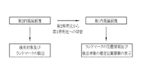
- FIG. 10 is an explanatory diagram showing detection of a detection target and landmarks from a second endoscopic image, and display of respective position information from a first endoscopic image;
- FIG. 4 is an explanatory diagram showing a series of flows in a tracking mode;
- FIG. 10 is an explanatory diagram for updating detection of landmarks used in position information estimation processing;
- the endoscope system 10 includes an endoscope 12, a light source device 13, a processor device 14, a display 15, a user interface 16, an expansion processor device 17, a display 18, a water supply device 19;
- the endoscope 12 is optically connected to the light source device 13 and electrically connected to the processor device 14 .
- the light source device 13 supplies illumination light to the endoscope 12 .
- the endoscope 12 is physically connected to the water supply device 19 and electrically connected to the processor device 14 .
- the water supply device 19 supplies water to the endoscope 12 .
- the endoscope 12 is used to illuminate an observation target with illumination light, capture an image of the observation target, and acquire an endoscopic image.
- the endoscope 12 includes an insertion portion 12a to be inserted into the body of an observation target, an operation portion 12b provided at the proximal end portion of the insertion portion 12a, a bending portion 12c provided at the distal end side of the insertion portion 12a, and a distal end portion. and a portion 12d.
- the bending portion 12c bends by operating the operation portion 12b.
- the distal end portion 12d irradiates an observation target with illumination light and receives reflected light from the observation target to capture an image of the observation target.
- the distal end portion 12d is directed in a desired direction by the bending motion of the bending portion 12c.
- the operation unit 12b includes a mode switching switch 12f used for mode switching operation, a still image acquisition instruction switch 12g used for instructing acquisition of a still image to be observed, and a zoom operation unit 12h used for operating the zoom lens 21b. , and a water supply switch 12i used for water supply operation.
- the processor device 14 is electrically connected with the display 15 and the user interface 16 .
- Processor unit 14 receives endoscopic images from endoscope 12 .
- the display 15 outputs and displays an observation target image or information processed by the processor device 14 .
- the user interface 16 has a keyboard, mouse, touch pad, microphone, etc., and has a function of receiving input operations such as function settings.
- Extended processor unit 17 is electrically connected to processor unit 14 .
- the extended processor device 17 receives images or various information from the processor device 14 .
- the display 18 outputs and displays images or information processed by the extended processor device 17 .
- the endoscope system 10 has a mono-emission mode, a multi-emission mode, and a tracking mode, which are switched by a mode changeover switch 12f.
- the mono light emission mode is a mode in which the observation target is continuously illuminated with illumination light of the same spectrum.
- the multi-light emission mode is a mode in which a plurality of illumination lights with different spectra are switched according to a specific pattern to illuminate the observation target.
- the illumination light includes normal light (broadband light such as white light) used to give brightness to the entire observation object and to observe the entire observation object, or light for emphasizing a specific region of the observation object. Special lights used for Also, in the mono light emission mode, the illumination light of a different spectrum may be switched by operating the mode switch 12f.
- the first illumination light and the second illumination light having different spectra may be switched.
- the tracking mode is not exclusive to the mono-emission mode and the multi-emission mode, and tracking is possible in both the mono-emission mode and the multi-emission mode.
- the real position information of the detection target is detected and the position of the detection target is detected so that the user can grasp the position of the detection target such as the bleeding point BS even if the image of the subject changes.
- the information and the positional information of landmarks associated with the positional information of the detection target are displayed on the display 18 (or the display 15 may be used).
- the illumination light is preferably a combination of violet light V, blue light B, green light G, and red light R.
- the violet light V preferably has a center wavelength of 405 ⁇ 10 nm and a wavelength range of 380 to 420 nm.
- the blue light B preferably has a center wavelength of 450 ⁇ 10 nm and a wavelength range of 420 to 500 nm.
- the green light G preferably has a wavelength range of 480-600 nm.
- the red light R preferably has a central wavelength of 620-630 nm and a wavelength range of 600-650 nm.
- the light source device 13 independently controls the light amounts of the four colors of violet light V, blue light B, green light G, and red light R.
- illumination light L having the same spectrum is continuously emitted for each frame.
- control is performed to change the light amounts of the four colors of violet light V, blue light B, green light G, and red light R according to a specific pattern.
- the specific pattern includes a first emission pattern in which the first illumination light L1 having the first spectrum is emitted continuously for two frames, and a second spectrum different from the first spectrum.
- a frame means that an imaging sensor (not shown) provided at the distal end portion 12d of the endoscope starts receiving reflected light from an observation target, and the output of accumulated charge signals based on the received light is completed. refers to the time between
- the processor device 14 may realize the function of the extended processor device 17 and replace it. In addition to the function of receiving endoscope images from the endoscope 12, the processor device 14 performs various processes implemented by functions realized by the extension processor device 17, which will be described later. In that case, the image or information that has undergone various processes may be displayed on the display 15 or may be displayed on the display 18 .
- the extended processor device 17 includes an image acquisition unit 20, a detection target detection unit 21, a landmark detection unit 22, a landmark processing unit 23, a display control unit 24, and an estimated position information calculation unit. It has a section 25 , a detection memory 26 and a processing timing setting section 27 .
- the extended processor device 17 is provided with a program memory for storing programs related to various processes. By executing the program by the processor provided in the extended processor device 17, the image acquisition unit 20, the detection target detection unit 21, the landmark detection unit 22, the landmark processing unit 23, and the display control unit 24 , the functions of the estimated position information calculation unit 25 and the processing timing setting unit 27 are realized.
- the display control unit 24 may perform display control of the display 15 in addition to the display control of the display 18 .
- the extended processor device 17 detects the landmark LM even when the detection target such as the bleeding point BS detected in the endoscopic image on the display 18 is not detected due to bleeding or the like.
- the position of the detection target can be estimated by performing position information estimation processing of the detection target.
- the result of the position information estimation process is indicated on the endoscope image by the estimated position display indicator 36 as detection target estimated position information.
- the image acquisition unit 20 acquires endoscopic images transmitted from the processor device 14 .
- the processor device 14 transmits the endoscopic image to the extended processor device 17 for each frame.
- the image acquisition unit 20 acquires an endoscopic image for each frame transmitted from the processor device 14 .
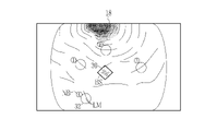
- the detection target detection unit 21 detects the detection target and acquires the real position information of the detection target by performing the first detection process on the endoscopic image. As shown in FIG. 5, in the endoscopic image on the display 18, when the bleeding point BS, which is one of the detection targets, is detected by the first detection process, the display control unit 24 controls the position of the bleeding point BS. Then, the detected position display indicator 30 is displayed on the display 18 . The position indicated by the detection position display indicator 30 is the actual position of the bleeding point BS.
- the detection target is preferably at least one of a bleeding point BS, a lesion such as cancer, a lesion highlighted by drug fluorescence (PDD (Photodynamic Diagnosis)), the shape of a specific organ, and a pattern of mucosa. .
- the detection target detection unit 21 is preferably a learned model that has undergone machine learning using teacher image data that includes the detection target.
- Machine learning includes supervised learning, semi-unsupervised learning, unsupervised learning, reinforcement learning, deep reinforcement learning, learning using neural networks, deep learning, and the like. Further, when detected by the first detection process, information on the detected detection target is stored in the detection memory 26 .
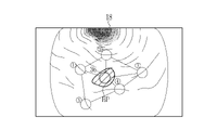
- the landmark detection unit 22 detects the landmark LM by performing the second detection process on the endoscopic image, and obtains the position information of the landmark LM. get.
- Landmarks LM include various structures such as blood vessels and duct structures, mucosal patterns, shapes of organs, markings operated by the user, markings after cauterization, and markings given inside the body (markings given by pigment, markings given at the time of incision, (marking with lame or marker applied to the swelling material to be injected). As shown in FIG. 6, when the landmark LM is detected in the second detection process in the endoscopic image in which the bleeding point BS, which is one of the detection targets, is detected in the first detection process, the position of the landmark LM is detected.
- a landmark position display indicator 32 is displayed on the display 18 .
- a plurality of landmarks LM need to be detected in order to execute the position information estimation process, and in this case, it is preferable to be able to distinguish the landmark position display indicators 32 from each other.
- a number NB (distinguishing number) is attached to each landmark position display indicator 32 for distinguishing.
- the landmark LM is placed not only near the detection target such as the bleeding area BP, but also at a position away from the detection target in order to eliminate factors that reduce the visibility of the detection target, such as pooled blood flowing out from the bleeding point BS. It is preferable to detect from
- the landmark processing unit 23 uses position information of a plurality of landmarks LM to perform landmark setting process for calculating estimated position information of the bleeding point BS.
- the number of landmarks LM used for landmark setting processing may be limited. For example, as shown in FIG. 7, when the upper limit is set to 4 for the number of landmarks to be used in the landmark setting process for an endoscopic image in which five landmarks LM are detected, five landmarks LM are detected in FIG.
- the landmark LM with the least reliable distinguishing number "4" among the LMs is excluded and is not displayed, and the distinguishing number of the landmark LM detected with the distinguishing number "5" is displayed as "4". Then, landmark setting processing is performed from the four landmarks LM.
- a credit threshold may be set to limit the number of users. In selecting the landmarks LM to be displayed on the display 18, the landmarks LM should be selected so as to surround the detection target rather than being concentrated in one place on the screen, and selected from landmarks useful for estimation. It is preferable to limit the number by
- the limitation of the landmarks LM to be detected it is possible to set an upper limit number or a threshold value and automatically detect the landmarks LM with high reliability. may be excluded from the scope of For example, the landmark LM with the identification number "4", which is indicated as having low credibility in the display mode of the landmark position display indicator 32 as shown in FIG. Set exclusions. Position information estimation processing is performed with the remaining landmarks LM.
- the setting of the limited number of landmarks LM may be performed before the tracking mode is turned on, or may be performed during the tracking mode including the second detection process.
- the landmark processing unit 23 performs a landmark setting process that associates the position information of the landmarks LM with the actual position information of the detection target.
- the landmark setting process as a method of associating the position information of the landmark LM with the real position information of the detection target, the detected position display indicator 30 and the landmark position display indicator 32 are linked as a link line. Tie at 34.
- the landmark position display indicator 32 must be connected to at least the detection position display indicator 30 by the link line 34 . Further, it is preferable to connect the different landmark position display indicators 32 with the link line 34 . Information about the position information of the landmark LM and the real position information of the detection target associated by the landmark setting process is stored in the detection memory 26 .
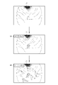
- the display control unit 24 performs a first display control process for displaying the real position information of the detection target and the position information of the landmark LM on the display 18 when the detection target is detected, A second display control process for displaying the position information of the landmark LM on the display 18 when the mark LM is detected, or a detection target when the detection target is not detected and the landmark setting process is performed. performs any of the third display control processing for displaying the estimated position information of .
- the detection position display indicator 30 is displayed as the real position information of the detection target
- the land mark LM is displayed as the position information of the landmark LM.
- a mark position display indicator 32 is displayed.
- the link line 34 is also displayed on the display 18 in the first display control process.
- the display of the detection target disappears from the endoscopic image.
- the detection target is no longer detected by the detection target detection unit 21 .
- the detection of the landmark LM is maintained by the landmark processing unit 23 if the landmark LM remains in the endoscopic image.
- the landmark position display indicator 32 is displayed on the display 18 as the position information of the landmark LM even though the detected position display indicator 30 is not displayed. be.
- the link line 34 is also displayed on the display 18 in the second display control process.
- the estimated position information calculation unit 25 calculates the estimated position information of the detection target by the position information estimation process based on the position information of the landmark LM when the detection target is not detected and the landmark setting process is completed. As shown in FIG. 9, when the display of the detection target disappears, the display control unit 24 maintains the display of the landmark position display indicator 32 on the display 18 by the second display control process. In this case, as a result of performing the position information estimation process, as shown in FIG. 10, as the estimated position information of the detection target, the estimated position display indicator 36 is displayed at the calculated position where the detection target exists. Add processing. Although the third display control process displays the estimated position information of the detection target as the estimated position display indicator 36, it may be displayed simultaneously with the landmark LM while continuing the second display control process.
- the position information estimation process it is preferable to estimate from the positional relationship between the landmark position display indicators 32, for example, the shape of the link formed from the link lines 34, and the like.
- the second display control process is not performed and only the third display control process is performed, as shown in FIG. 5, the landmark position display indicator 32 and the link line 34 are not displayed, and only the estimated position display indicator 36 is displayed. becomes.
- the detected position display indicator 30, the landmark position display indicator 32, and the estimated position display indicator 36 are displayed in different display modes on the display 18 for easy distinction.
- the detected position display indicator 30 has a square periphery
- the landmark position display indicator 32 has a circle periphery
- the estimated position display indicator 36 has a double circle periphery (except in FIG. 11). see also figure).
- the detected position display indicator 30 and the estimated position display indicator 36 have the same or very similar display modes, if there is an erroneous detection of the detection target, the estimated position display indicator 30 calculated based on the erroneous detection information There is a possibility that the indicator 36 cannot be recognized as false detection.
- the processing section for performing the second processing in the landmark processing section 23 is preferably a learned model for landmark detection that has been machine-learned using teacher image data including the landmark LM.
- the display mode (color, line style, etc.) of the position information of the landmark LM is changed according to the reliability. preferably changed. For example, as shown in FIG. 6, when the reliability of the landmark LM with the distinguishing number "4" is lower than the reliability of the other landmarks LM, the landmark with the distinguishing number "4" It is preferable to make the display mode of the landmark position display indicator 32 of the LM (dotted line in FIG. 6) different from the display mode of the landmark position display indicator 32 of the other landmarks LM (solid line in FIG. 8).
- the estimated position information calculation unit 25 calculates the reliability of the estimated position information along with the calculation of the estimated position information. For example, it is preferable to calculate the certainty factor of the estimated position information as the certainty factor of the estimated position information from a machine-learned model. The user can select an operation for the observation target according to the reliability of the estimated position information. For example, when the reliability is high, the bleeding point BS is treated for hemostasis, whereas when the reliability is low, no hemostasis treatment is performed so as not to stop bleeding at the wrong location.
- the estimated position information when the estimated position information is represented by the color information for position display, when the reliability of the estimated position information is a certain value or higher, the color information for position display The density is increased, and when the reliability of the estimated position information is low, i.e., less than a certain value, the density of the position display color information is decreased.
- the size of the position display graphic is reduced when the reliability is high, and the size of the position display graphic is increased when the reliability is low.
- the line thickness of the position display graphic when the reliability is high, the line thickness of the position display graphic is thickened, and when the reliability is low, the line thickness of the position display graphic is thinned.
- the line type of the position display graphic When the reliability is high, the line type of the position display graphic is set to a solid line, and when the reliability is low, the line type of the position display graphic is set to a dotted line.
- the display control unit 24 may notify the result of each process with a notification sound and on the display 18.
- the result of the first detection processing is "detection target detection”.
- the landmark LM is detected by the second detection process
- the landmark position display indicator 32 may be displayed and the notification "landmark detected” may be displayed in the notification field 40 on the display 18.
- FIG. The notification column 40 does not always need to be expanded, and is temporarily displayed for 5 seconds or the like when a notification reason occurs. Further, the content of the notification may be not only displayed on the display 18, but also may be sounded. Examples of notification will be described below separately for the case where the landmark setting is completed and the case where the landmark setting is not completed, which is the condition for starting the position information estimation process when the detection target is not detected.
- the detection targets detected in FIG. When the landmark setting process is completed, as shown in FIG. 14, the detection targets detected in FIG. When the link line 34 is formed in , the display 18 is notified that "landmark setting processing is completed". In addition, when the landmark setting process is completed and the detection target is not detected due to the bleeding area BP or the like, "detection target not detected” and “estimated position calculation start” are notified, and the position information estimation process is performed. . When the position information estimation process is executed and the estimated position information is calculated, the notification of "estimated position calculation” and the estimated position display indicator 36 are displayed at the estimated position of the detection target.
- the required number of landmarks LM for the landmark setting process is the number that can surround the detection target, and is at least three landmarks LM. Also, the required number may be set to four or more by user operation or the like. If the landmark setting process cannot be executed, it is preferable to restart from the first detection process or the second detection process.
- the number of acquisitions of position information in the tracking mode may be displayed on the display 18.
- an acquisition number information display field 41 for displaying the number of acquisitions of position information in the tracking mode is expanded on the upper right of the display 18 .
- the acquisition number information display column 41 is always expanded, and the number of positions of the detection target and landmark LM detected by the first detection process and the second detection process in the tracking mode, and the estimated position of the detection target calculated by the position information calculation process. It is preferable that the number of acquisitions of information is displayed in characters.
- the contents of the processing in progress such as “first detection processing in progress”, “landmark setting in progress”, and “position information estimation processing in progress” may be displayed.
- Either one of the notification column 40 and the acquisition number information display column 41 in FIGS. 13 to 15 may be used, or both may be used in combination.
- the number of acquisitions may include the number of detection targets and the number of landmarks in addition to the number of estimated position information.
- the processing timing setting unit 27 preferably sets the start timing or end timing of the first detection processing, the start timing or end timing of the second detection processing, and the start timing or end timing of the position information estimation processing (see FIG. 17). reference). By setting the start timing and the end timing in this way so that the first detection process or the position information estimation process is not always performed, erroneous detection can be suppressed. In addition, when it is determined that the first detection process or the position information estimation process is unnecessary, it is possible to make it easier to see other than the detection target such as the bleeding point BS by hiding the actual position information and the estimated position information of the detection target. can.
- the start timing of the first detection process is the timing when the endoscope image detects the water supply emitted from the distal end of the endoscope 12 toward the observation target (at the time of water supply detection).
- the timing at which an incision made on a part of the observation target by a treatment tool or the like is detected in the endoscopic image (when the incision is detected), or the treatment tool protruding from the distal end of the endoscope 12 is detected in the endoscopic image. It is preferable that it is the timing detected by (at the time of detection of the treatment instrument), or the like.
- the end timing of the first detection process is the timing when the detection target or bleeding cannot be detected for a certain period of time (when the first detection process fails), and the timing when the detected detection target disappears for a certain period of time. Later timing (after a certain period of time has elapsed since the detection target disappeared), timing at which the hemostasis point is detected (when the hemostasis point is detected), or timing after a certain period of time has elapsed without increasing the bleeding area BP (when the bleeding area has not expanded) is preferred.
- the observation target may be changed.
- a bleeding area supplementing section (not shown) having a function of capturing changes in the area such as the position and enlargement of the bleeding area BP may be provided.
- the start timing of the second detection process is preferably the timing at which the detection target is detected by the first detection process (when the detection target is detected).
- the end timing of the second detection process is set by the timing after a certain period of time has passed since the latest landmark LM was detected (after a certain period of time has passed since the detection of the landmark), or by the number of detected landmarks LM. It is preferable that the timing reaches the upper limit number (after reaching the upper limit number of landmark detections).
- the start timing of the position information estimation process is after the landmark is set and when the detection target disappears.
- the end timing of the position information estimation process is the timing when the estimated position information could not be calculated by the position information estimation process due to the disappearance of the landmark (when the position information estimation process fails), and the bleeding point. Timing at which the hemostasis point, which is the result of performing hemostasis treatment with a tool or the like, is detected (when the hemostasis point is detected), or timing at which bleeding cannot be confirmed between the estimated position display indicator 36 and its surroundings (when no bleeding is detected at the estimated position). preferably. If the tracking mode is to be continued even if the position information estimation process fails, it is preferable to redo the first detection process.
- the re-detection start timing of the first detection process is the timing at which the detection target or disappears before the completion of the landmark setting process (when the landmark setting process fails), and the timing at which the landmark disappears before the completion of the position information estimation process (position When the information estimation process fails).
- the detection target and the landmark LM are detected from the second endoscope image based on the second illumination light, and the landmark setting process is performed. It is preferable to switch from the illumination light to the first illumination light and display the estimated position information of the detection target and the position information of the landmark LM on the first endoscopic image based on the first illumination light. As a result, when switching from the second illumination light to the first illumination light, the position or area of the detection target is not lost.
- the second illumination light is preferably light suitable for detection of a detection target, for example, special light including violet light capable of highlighting a structure.
- the first illumination light is preferably light suitable for displaying the actual position information of the detection target, the position information of the landmarks LM, and the estimated position information of the detection target, such as white light.
- the mode selector switch 12f is operated to turn on the tracking mode.
- the first detection process is performed on the endoscopic image.
- the first detection process when the detection target including the bleeding point BS is detected, the real position information of the detection target is acquired. If the detected detection target is a new detection target, landmark setting processing is performed.
- the landmark setting process by performing the second detection process on the endoscopic image, the landmark LM is detected and the position information of the landmark LM is acquired. In addition, the position information of the landmark LM and the real position information of the detection target are associated.
- the position information of the landmarks LM and the real position information of the detection target that are associated with each other are displayed on the display 18 .
- the display 18 displays the position information of the landmark LM already associated in the landmark setting process and the real position information of the detection target.
- Whether or not it is a new detection target is determined by whether or not there is information on the detection target in the detection memory 26 .
- the information on the detection target already stored in the detection memory 26 is deleted, and the information on the new detection target is newly stored in the detection memory 26 .
- the detection target cannot be detected by the first detection process, it is determined whether or not the landmark setting process has already been performed (determining whether or not the landmark setting process is in progress). If the landmark setting process has already been performed, the estimated position information of the detection target is calculated based on the position information of the landmark LM. Then, the calculated estimated position information of the detection target and the position information of the landmark LM are displayed on the display 18 . The above series of processes are repeated as long as bleeding is detected or estimated. Then, when the mode changeover switch 12f is operated to turn off the tracking mode, the detection of the detection target and the like are terminated.
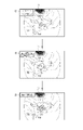
- the endoscope 12 Since the operation of the endoscope 12 is performed manually, even if the estimated position of the detection target is continuously captured in the endoscopic image, the range projected by the endoscopic image changes, and landmarks surrounding the estimated position of the detection target are displayed. If the LM does not fit within the endoscopic image, the organ may be deformed and the relationship between the landmark and the detection target may change. As shown in FIG. 20, when the endoscope 12 captures the next frame, a new landmark LM2 is detected at a position different from the landmark LM used for the position information estimation process, and used for the position information estimation process. The landmark LM may be updated and the display of the estimated position display indicator 36 on the bleeding area BP may be continued.
- FIG. 20A displays the estimated position display indicator 36 in the position information estimation process using the landmark LM.
- a new frame is acquired, as shown in FIG. 20(B), a new landmark LM2 surrounding the estimated position of the detection target is detected in accordance with the movement direction of the previous and subsequent frames, and the new landmark position is displayed.
- indicator 38 is displayed.
- the new landmark LM2 is subjected to a new landmark setting process for associating with the detection target estimated position information, and a new relative relationship is calculated. New relative relationships are indicated by new link lines 39 .
- the new link line 39 is preferably less conspicuous than the link line 34 and preferably uses a dotted line or the like so as not to be confused.
- the number NB (distinguishing number) for distinguishing each landmark position display indicator 32 can also be assigned to the new landmark position display indicator 38, but it is not necessary to assign the number NB if the visibility becomes poor. good. In that case, the portion assigned from the landmark position display indicator 32 may also be hidden.
- the new relative relationship may be calculated using not only the detection target and the new landmark LM2, but also the landmark LM before updating.
- the landmarks LM to be used in duplicate are preferably positions that remain within the endoscope screen with respect to the moving direction of frame photography.
- the new landmark setting process when the endoscope 12 acquires a new frame of the endoscopic image and the landmark LM required for the position information estimation process is not recognized, as shown in FIG. , position information estimation processing based on the new relative relationship is performed, the detection target estimated position information is calculated, and the estimated position display indicator 36 is displayed on the display 18 . Since the position information estimation processing based on the landmark LM is finished, the link line 34 is hidden and the new link line 39 is displayed as a solid line like the link line 34 . If there is a landmark LM that continues to be recognized even after the position information estimation process based on the landmark LM ends, it may be incorporated into the new relative relationship.
- the new landmark LM2 is the landmark LM
- the new link line 39 is the link line 34
- the relative relationship of the new landmark LM2 is updated by the landmark setting process
- the landmark LM performs the position information estimation process.
- various processes such as the image acquisition unit 20, the detection target detection unit 21, the landmark processing unit 23, the display control unit 24, the estimated position information calculation unit 25, the detection memory 26, or the processing timing setting unit are performed.
- the hardware structure of the executing processing unit is various processors as shown below.
- Various processors include CPU (Central Processing Unit), GPU (Graphical Processing Unit), FPGA (Field Programmable Gate Array), etc.
- Programmable Logic Device which is a processor whose circuit configuration can be changed after manufacturing, and a dedicated electric circuit, which is a processor with a circuit configuration specially designed to perform various processes. .
- One processing unit may be composed of one of these various processors, or a combination of two or more processors of the same or different type (for example, a plurality of FPGAs, a combination of CPU and FPGA, or a combination of CPU and A combination of GPUs, etc.).
- a plurality of processing units may be configured by one processor.
- configuring a plurality of processing units in one processor first, as represented by computers such as clients and servers, one processor is configured by combining one or more CPUs and software, There is a form in which this processor functions as a plurality of processing units.
- SoC System On Chip
- the various processing units are configured by using one or more of the above various processors as a hardware structure.
- the hardware structure of these various processors is, more specifically, an electric circuit in the form of a combination of circuit elements such as semiconductor elements.
- the hardware structure of the storage unit is a storage device such as an HDD (hard disc drive) or SSD (solid state drive).
- endoscope system 12 endoscope 12a insertion portion 12b operation portion 12c bending portion 12d tip portion 12f mode changeover switch 12g still image acquisition instruction switch 12h zoom operation portion 12i water supply switch 13 light source device 14 processor device 15 display 16 user interface 17 Extended processor device 18 Display 19 Water supply device 20 Image acquisition unit 21 Detection target detection unit 22 Landmark detection unit 23 Landmark processing unit 24 Display control unit 25 Estimated position calculation unit 26 Detection memory 27 Processing timing setting unit 30 Detection position display indicator 32 Landmark position display indicator 34 Link line 36 Estimated position display indicator 38 New landmark display indicator 39 New link line 40 Notification column 41 Acquired number information display column BS Bleeding point BP Bleeding area LM Landmark LM2 New Landmark
Abstract
Description
12 内視鏡
12a 挿入部
12b 操作部
12c 湾曲部
12d 先端部
12f モード切替スイッチ
12g 静止画取得指示スイッチ
12h ズーム操作部
12i 送水スイッチ
13 光源装置
14 プロセッサ装置
15 ディスプレイ
16 ユーザーインターフェース
17 拡張プロセッサ装置
18 ディスプレイ
19 送水装置
20 画像取得部
21 検出対象検出部
22 ランドマーク検出部
23 ランドマーク処理部
24 表示制御部
25 推定位置算出部
26 検出メモリ
27 処理タイミング設定部
30 検出位置表示用インジケータ
32 ランドマーク位置表示用インジケータ
34 リンクライン
36 推定位置表示用インジケータ
38 新規のランドマーク表示用インジケータ
39 新規のリンクライン
40 通知欄
41 取得数情報表示欄
BS 出血点
BP 出血領域
LM ランドマーク
LM2 新規のランドマーク
10
Claims (19)
- プロセッサを備え、
前記プロセッサが、内視鏡画像を取得し、
前記内視鏡画像に対して第1検出処理を行うことによって、検出対象の検出対象実位置情報を取得し、
前記検出対象実位置情報を検出した場合に、前記内視鏡画像に対して第2検出処理を行うことによってランドマークの位置情報を取得し、
前記検出対象実位置情報と、前記ランドマークの位置情報とを関連付けるランドマーク設定処理を行い、
前記ランドマーク設定処理の後に、前記検出対象実位置情報が取得されず、且つ、前記ランドマーク設定処理済みの場合に位置情報推定処理を行い、検出対象推定位置情報を算出し、
ディスプレイに前記検出対象推定位置情報を表示する内視鏡システム。 with a processor
the processor acquires an endoscopic image;
Acquiring detection target real position information of a detection target by performing a first detection process on the endoscopic image;
Acquiring landmark position information by performing a second detection process on the endoscopic image when the detection target real position information is detected;
performing landmark setting processing for associating the detection target real position information with the position information of the landmark;
After the landmark setting process, if the actual position information of the detection target is not acquired and the landmark setting process is completed, position information estimation processing is performed to calculate estimated position information of the detection target;
An endoscope system that displays the estimated detection target position information on a display. - 前記プロセッサが、
前記検出対象実位置情報、前記検出対象推定位置情報、及び前記ランドマークの位置情報をそれぞれ異なる態様で前記ディスプレイに表示する請求項1記載の内視鏡システム。 the processor
2. The endoscope system according to claim 1, wherein the detection target actual position information, the detection target estimated position information, and the landmark position information are displayed in different modes on the display. - 前記プロセッサが、
通知音、及び前記ディスプレイにおける通知の両方、又は少なくともどちらか一方を使用する通知を行い、
前記第1検出処理中に前記検出対象実位置情報を検出した時、又は前記第2検出処理中に前記ランドマークの位置情報を検出した時の少なくともいずれかに前記通知を行う請求項1または2記載の内視鏡システム。 the processor
notification using both, or at least one of, a notification sound and a notification on the display;
3. The notification is made at least either when the detection target real position information is detected during the first detection process or when the position information of the landmark is detected during the second detection process. An endoscopic system as described. - 前記プロセッサが、
通知音、及び前記ディスプレイにおける通知の両方、又は少なくともどちらか一方を使用する通知を行い、
前記ランドマーク設定処理の結果、前記ランドマーク設定処理が完了した時、前記検出対象の非検出時、前記位置情報推定処理が開始した時、又は前記位置情報推定処理中に前記検出対象推定位置情報を算出した時の少なくともいずれかに前記通知を行う請求項1又は2記載の内視鏡システム。 the processor
notification using both, or at least one of, a notification sound and a notification on the display;
As a result of the landmark setting process, when the landmark setting process is completed, when the detection target is not detected, when the position information estimation process is started, or during the position information estimation process, the detection target estimated position information 3. The endoscope system according to claim 1 or 2, wherein the notification is made at least one of the times when the is calculated. - 前記プロセッサが、
通知音、及び前記ディスプレイにおける通知の両方、又は少なくともどちらか一方を使用する通知を行い、
前記第2検出処理中に前記ランドマークの位置情報が必要数を取得できず前記ランドマーク設定処理が実行不可になった時、及び前記ランドマーク設定処理の完了前に、前記検出対象実位置情報が消失し、前記ランドマーク設定処理が失敗した時に前記通知を行う請求項1又は2記載の内視鏡システム。 the processor
notification using both, or at least one of, a notification sound and a notification on the display;
When the landmark setting process cannot be executed because the required number of landmark position information cannot be acquired during the second detection process, and before the completion of the landmark setting process, the detection target real position information disappears and the landmark setting process fails. - 前記プロセッサが、
前記検出対象推定位置情報の数量を少なくとも含む文字表示による位置情報の取得数情報を前記ディスプレイに表示する請求項1ないし5いずれか1項記載の内視鏡システム。 the processor
6. The endoscope system according to any one of claims 1 to 5, wherein acquisition number information of position information in character display including at least the quantity of the estimated detection target position information is displayed on the display. - 前記プロセッサが、
前記検出対象実位置情報及び前記ランドマークの位置情報の取得数情報を前記ディスプレイに表示する請求項6記載の内視鏡システム。 the processor
7. The endoscope system according to claim 6, wherein acquisition number information of said detection target real position information and said landmark position information is displayed on said display. - 前記プロセッサは、
前記位置情報推定処理に使用する前記ランドマークの数を制限する請求項1ないし7いずれか1項記載の内視鏡システム。 The processor
The endoscope system according to any one of claims 1 to 7, wherein the number of landmarks used in the position information estimation process is limited. - 前記プロセッサは、
前記ランドマークのうち、前記ディスプレイに表示する前記ランドマークを選択し、前記ディスプレイに表示する前記ランドマークを制限する請求項1ないし7いずれか1項記載の内視鏡システム。 The processor
The endoscope system according to any one of claims 1 to 7, wherein the landmarks to be displayed on the display are selected from the landmarks, and the landmarks to be displayed on the display are restricted. - 前記プロセッサは、
前記位置情報推定処理における前記ランドマークの使用の可否を指定するユーザ操作を受け付ける請求項1ないし9いずれか1項記載の内視鏡システム。 The processor
10. The endoscope system according to any one of claims 1 to 9, wherein a user's operation for designating whether or not to use the landmark in the position information estimation process is accepted. - 前記内視鏡画像には、第1照明光に基づく第1内視鏡画像と、前記第1照明光とスペクトルが異なる第2照明光に基づく第2内視鏡画像とが含まれ、
前記プロセッサが、前記第1内視鏡画像から前記第1検出処理、前記第2検出処理、を行い、前記第2内視鏡画像から前記検出対象実位置情報、前記検出対象推定位置情報、及び前記ランドマークの位置情報を前記ディスプレイに表示する請求項1ないし10いずれか1項記載の内視鏡システム。 The endoscopic images include a first endoscopic image based on a first illumination light and a second endoscopic image based on a second illumination light having a spectrum different from that of the first illumination light,
The processor performs the first detection process and the second detection process from the first endoscopic image, and performs the detection target actual position information, the detection target estimated position information, and the detection target estimated position information from the second endoscopic image. The endoscope system according to any one of claims 1 to 10, wherein position information of said landmark is displayed on said display. - 前記第1検出処理の開始タイミングは、送水検出時、切開検出時、処置具検出時、またはユーザ操作時のいずれかであり、
前記第1検出処理の終了タイミングは、検出対象未検出で一定時間経過した時、前記検出対象の消失から一定時間経過した時、出血領域不拡大時、またはユーザ操作時のいずれかであり、
前記第2検出処理の開始タイミングは、前記検出対象の検出時であり、
前記第2検出処理の終了タイミングは、前記検出対象の消失時、一定時間内に必要数の前記ランドマークの非検出時、またはユーザ操作時のいずれかであり、
前記位置情報推定処理の開始タイミングは、前記ランドマーク設定処理が完了し、且つ前記検出対象の消失時であり、
前記位置情報推定処理の終了タイミングは、前記ランドマークの非検出時、止血点の検出時、前記検出対象の推定位置周辺の出血非検出時、またはユーザ操作時のいずれかである請求項1ないし11いずれか1項記載の内視鏡システム。 The start timing of the first detection process is either when water supply is detected, when incision is detected, when a treatment instrument is detected, or when a user operates,
The end timing of the first detection process is either when a certain period of time has elapsed without the detection target being detected, when a certain period of time has elapsed since the disappearance of the detection target, when the bleeding area does not expand, or when a user operates,
The start timing of the second detection process is when the detection target is detected,
The end timing of the second detection process is either when the detection target disappears, when the required number of landmarks are not detected within a certain period of time, or when a user operates,
the start timing of the position information estimation process is when the landmark setting process is completed and the detection target disappears;
The end timing of the position information estimation process is any one of when the landmark is not detected, when a bleeding point is detected, when bleeding is not detected around the estimated position of the detection target, or when a user operates. 11. The endoscope system according to any one of items 11-11. - 前記第1検出処理の再開タイミングは、前記ランドマーク設定処理の失敗時、前記位置情報推定処理の失敗時、またはユーザ操作時のいずれかである請求項12記載の内視鏡システム。 13. The endoscope system according to claim 12, wherein the restart timing of the first detection process is either when the landmark setting process fails, when the position information estimation process fails, or when a user operates.
- 前記ランドマークは、粘膜模様、臓器の形状、ユーザ操作によるマーキングの少なくともいずれかの位置情報である請求項1ないし13いずれか1項記載の内視鏡システム。 The endoscope system according to any one of claims 1 to 13, wherein the landmark is position information of at least one of a mucosal pattern, shape of an organ, and marking by user operation.
- プロセッサを備え、
前記プロセッサが、内視鏡画像を取得し、
前記内視鏡画像に対して第1検出処理を行うことによって、検出対象の検出対象実位置情報を取得し、
前記内視鏡画像に対して第2検出処理を行うことによってランドマークの位置情報を取得し、
前記内視鏡画像が更新されて、前記検出対象実位置情報、又は、前記ランドマークの位置情報に基づく位置情報推定処理から得られる検出対象推定位置情報を取得する毎に、前記検出対象実位置情報又は前記検出対象推定位置情報のいずれかと、前記ランドマークの位置情報とを関連付けて相対関係を設定するランドマーク設定処理を行い、
ディスプレイに前記検出対象実位置情報、又は、前記検出対象推定位置情報を表示する内視鏡システム。 with a processor
the processor acquires an endoscopic image;
Acquiring detection target real position information of a detection target by performing a first detection process on the endoscopic image;
Acquiring landmark position information by performing a second detection process on the endoscopic image;
Every time the endoscopic image is updated and the actual detection target position information or the estimated detection target position information obtained by position information estimation processing based on the position information of the landmark is acquired, the actual detection target position perform a landmark setting process for setting a relative relationship by associating either the information or the estimated detection target position information with the position information of the landmark,
An endoscope system that displays the detection target actual position information or the detection target estimated position information on a display. - 前記プロセッサが、
前記位置情報推定処理が継続する状態で、新たなフレームの前記内視鏡画像を取得して、新規のランドマークを検出した場合において、前記ランドマーク設定処理として、前記検出対象推定位置情報と、前記新規のランドマークとを関連付けて新規の相対関係を設定する新規のランドマーク設定処理を行い、
前記新規のランドマーク設定処理の後に、前記位置情報推定処理に必要な前記ランドマークが認識されない場合、前記新規の相対関係に基づく位置情報推定処理を行い、新規の検出対象推定位置情報を算出し、
前記ディスプレイに前記新規の検出対象推定位置情報を表示する請求項15記載の内視鏡システム。 the processor
When the endoscopic image of a new frame is acquired and a new landmark is detected while the position information estimation process continues, the landmark setting process includes the estimated detection target position information, performing a new landmark setting process for setting a new relative relationship by associating with the new landmark;
After the new landmark setting process, if the landmark required for the position information estimation process is not recognized, the position information estimation process based on the new relative relationship is performed to calculate new estimated position information of the detection target. ,
16. The endoscope system according to claim 15, wherein the new estimated detection target position information is displayed on the display. - 前記ランドマーク及び前記新規のランドマークは、粘膜模様、臓器の形状、ユーザ操作によるマーキングの少なくともいずれかの位置情報である請求項16記載の内視鏡システム。 The endoscope system according to claim 16, wherein the landmarks and the new landmarks are position information of at least one of mucosal patterns, organ shapes, and markings by user operation.
- プロセッサを備える内視鏡システムの作動方法において、
内視鏡画像を取得するステップと、
前記内視鏡画像に対して第1検出処理を行うことによって、検出対象の検出対象実位置情報を取得するステップと、
前記検出対象実位置情報を検出した場合に、前記内視鏡画像に対して第2検出処理を行うことによってランドマークの位置情報を取得するステップと、
前記検出対象実位置情報と、前記ランドマークの位置情報とを関連付けるランドマーク設定処理を行うステップと、
前記ランドマーク設定処理の後に、前記検出対象実位置情報が取得されず、且つ、前記ランドマーク設定処理済みの場合に位置情報推定処理を行い、検出対象推定位置情報を算出するステップと、
ディスプレイに前記検出対象推定位置情報を表示するステップとを有する内視鏡システムの作動方法。 A method of operating an endoscopic system comprising a processor comprising:
acquiring an endoscopic image;
obtaining detection target real position information of a detection target by performing a first detection process on the endoscopic image;
obtaining landmark position information by performing a second detection process on the endoscopic image when the detection target real position information is detected;
performing a landmark setting process for associating the detection target real position information with the position information of the landmark;
a step of performing position information estimation processing to calculate estimated detection target position information when the actual detection target position information has not been obtained after the landmark setting processing and the landmark setting processing has been completed;
and displaying the estimated detection target position information on a display. - 前記プロセッサは、
前記検出対象実位置情報、前記検出対象推定位置情報、及び前記ランドマークの位置情報をそれぞれ異なる態様で前記ディスプレイに表示するステップを有する請求項18記載の内視鏡システムの作動方法。
The processor
19. The method of operating an endoscope system according to claim 18, further comprising the step of displaying the actual position information of the detection object, the estimated position information of the detection object, and the position information of the landmark on the display in different manners.
Priority Applications (4)
| Application Number | Priority Date | Filing Date | Title |
|---|---|---|---|
| EP22766705.2A EP4306035A1 (en) | 2021-03-09 | 2022-02-08 | Endoscope system and method for operating same |
| JP2023505227A JPWO2022190740A1 (en) | 2021-03-09 | 2022-02-08 | |
| CN202280020345.6A CN116963655A (en) | 2021-03-09 | 2022-02-08 | Endoscope system and working method thereof |
| US18/463,930 US20230421887A1 (en) | 2021-03-09 | 2023-09-08 | Endoscope system and method of operating the same |
Applications Claiming Priority (2)
| Application Number | Priority Date | Filing Date | Title |
|---|---|---|---|
| JP2021-037558 | 2021-03-09 | ||
| JP2021037558 | 2021-03-09 |
Related Child Applications (1)
| Application Number | Title | Priority Date | Filing Date |
|---|---|---|---|
| US18/463,930 Continuation US20230421887A1 (en) | 2021-03-09 | 2023-09-08 | Endoscope system and method of operating the same |
Publications (1)
| Publication Number | Publication Date |
|---|---|
| WO2022190740A1 true WO2022190740A1 (en) | 2022-09-15 |
Family
ID=83227884
Family Applications (1)
| Application Number | Title | Priority Date | Filing Date |
|---|---|---|---|
| PCT/JP2022/004837 WO2022190740A1 (en) | 2021-03-09 | 2022-02-08 | Endoscope system and method for operating same |
Country Status (5)
| Country | Link |
|---|---|
| US (1) | US20230421887A1 (en) |
| EP (1) | EP4306035A1 (en) |
| JP (1) | JPWO2022190740A1 (en) |
| CN (1) | CN116963655A (en) |
| WO (1) | WO2022190740A1 (en) |
Citations (8)
| Publication number | Priority date | Publication date | Assignee | Title |
|---|---|---|---|---|
| JP2011036371A (en) | 2009-08-10 | 2011-02-24 | Tohoku Otas Kk | Medical image recording apparatus |
| JP2015529489A (en) | 2012-07-25 | 2015-10-08 | インテュイティブ サージカル オペレーションズ, インコーポレイテッド | Efficient and interactive bleeding detection in surgical systems |
| WO2019106712A1 (en) * | 2017-11-28 | 2019-06-06 | オリンパス株式会社 | Endoscope image processing device and endoscope image processing method |
| WO2019202827A1 (en) | 2018-04-17 | 2019-10-24 | ソニー株式会社 | Image processing system, image processing device, image processing method, and program |
| WO2019244255A1 (en) * | 2018-06-19 | 2019-12-26 | オリンパス株式会社 | Endoscope image processing device and endoscope image processing method |
| WO2020080209A1 (en) * | 2018-10-18 | 2020-04-23 | ソニー株式会社 | Medical-use observation system, medical-use observation device and medical-use observation method |
| WO2020110278A1 (en) * | 2018-11-30 | 2020-06-04 | オリンパス株式会社 | Information processing system, endoscope system, trained model, information storage medium, and information processing method |
| JP2021029979A (en) * | 2019-08-29 | 2021-03-01 | 国立研究開発法人国立がん研究センター | Teaching data generation device, teaching data generation program, and teaching data generation method |
-
2022
- 2022-02-08 JP JP2023505227A patent/JPWO2022190740A1/ja active Pending
- 2022-02-08 WO PCT/JP2022/004837 patent/WO2022190740A1/en active Application Filing
- 2022-02-08 CN CN202280020345.6A patent/CN116963655A/en active Pending
- 2022-02-08 EP EP22766705.2A patent/EP4306035A1/en active Pending
-
2023
- 2023-09-08 US US18/463,930 patent/US20230421887A1/en active Pending
Patent Citations (8)
| Publication number | Priority date | Publication date | Assignee | Title |
|---|---|---|---|---|
| JP2011036371A (en) | 2009-08-10 | 2011-02-24 | Tohoku Otas Kk | Medical image recording apparatus |
| JP2015529489A (en) | 2012-07-25 | 2015-10-08 | インテュイティブ サージカル オペレーションズ, インコーポレイテッド | Efficient and interactive bleeding detection in surgical systems |
| WO2019106712A1 (en) * | 2017-11-28 | 2019-06-06 | オリンパス株式会社 | Endoscope image processing device and endoscope image processing method |
| WO2019202827A1 (en) | 2018-04-17 | 2019-10-24 | ソニー株式会社 | Image processing system, image processing device, image processing method, and program |
| WO2019244255A1 (en) * | 2018-06-19 | 2019-12-26 | オリンパス株式会社 | Endoscope image processing device and endoscope image processing method |
| WO2020080209A1 (en) * | 2018-10-18 | 2020-04-23 | ソニー株式会社 | Medical-use observation system, medical-use observation device and medical-use observation method |
| WO2020110278A1 (en) * | 2018-11-30 | 2020-06-04 | オリンパス株式会社 | Information processing system, endoscope system, trained model, information storage medium, and information processing method |
| JP2021029979A (en) * | 2019-08-29 | 2021-03-01 | 国立研究開発法人国立がん研究センター | Teaching data generation device, teaching data generation program, and teaching data generation method |
Also Published As
| Publication number | Publication date |
|---|---|
| EP4306035A1 (en) | 2024-01-17 |
| JPWO2022190740A1 (en) | 2022-09-15 |
| US20230421887A1 (en) | 2023-12-28 |
| CN116963655A (en) | 2023-10-27 |
Similar Documents
| Publication | Publication Date | Title |
|---|---|---|
| US20220095903A1 (en) | Augmented medical vision systems and methods | |
| JP5486432B2 (en) | Image processing apparatus, operating method thereof, and program | |
| JPWO2018159363A1 (en) | Endoscope system and operation method thereof | |
| WO2023103467A1 (en) | Image processing method, apparatus and device | |
| JP7315576B2 (en) | Medical image processing device, operating method and program for medical image processing device, diagnostic support device, and endoscope system | |
| JP7138771B2 (en) | Diagnosis support device, diagnosis support method and program | |
| US11867896B2 (en) | Endoscope system and medical image processing system | |
| WO2019220916A1 (en) | Medical image processing device, medical image processing method, and endoscope system | |
| US20240087113A1 (en) | Recording Medium, Learning Model Generation Method, and Support Apparatus | |
| EP3991632A1 (en) | Endoscope system and endoscope device | |
| JP2008054763A (en) | Medical image diagnostic apparatus | |
| WO2022190740A1 (en) | Endoscope system and method for operating same | |
| WO2022191129A1 (en) | Endoscope system and method for operating same | |
| JP7146318B1 (en) | Computer program, learning model generation method, and surgery support device | |
| WO2022191128A1 (en) | Endoscope system and method for operating same | |
| EP4111938A1 (en) | Endoscope system, medical image processing device, and operation method therefor | |
| US20220414885A1 (en) | Endoscope system, medical image processing device, and operation method therefor | |
| WO2023153069A1 (en) | Medical image device, endoscope system, and medical certificate creation system | |
| US20230096406A1 (en) | Surgical devices, systems, and methods using multi-source imaging | |
| WO2021149120A1 (en) | Device for creating medical image data for use in learning, method for creating medical image data for use in learning, and program | |
| WO2024053697A1 (en) | Surgery assistance program, surgery assistance device, and surgery assistance method | |
| JP2023143318A (en) | Image processing device, medical diagnostic device, endoscope device, and image processing method | |
| JP2023007331A (en) | Endoscope system, medical image processing device, and operation method therefor | |
| WO2023052940A1 (en) | Surgical devices, systems, and methods using multi-source imaging | |
| JP2023112340A (en) | Endoscope system and operation method thereof |
Legal Events
| Date | Code | Title | Description |
|---|---|---|---|
| 121 | Ep: the epo has been informed by wipo that ep was designated in this application |
Ref document number: 22766705 Country of ref document: EP Kind code of ref document: A1 |
|
| WWE | Wipo information: entry into national phase |
Ref document number: 2023505227 Country of ref document: JP |
|
| WWE | Wipo information: entry into national phase |
Ref document number: 202280020345.6 Country of ref document: CN |
|
| WWE | Wipo information: entry into national phase |
Ref document number: 2022766705 Country of ref document: EP |
|
| NENP | Non-entry into the national phase |
Ref country code: DE |
|
| ENP | Entry into the national phase |
Ref document number: 2022766705 Country of ref document: EP Effective date: 20231009 |