WO2022191129A1 - Endoscope system and method for operating same - Google Patents
Endoscope system and method for operating same Download PDFInfo
- Publication number
- WO2022191129A1 WO2022191129A1 PCT/JP2022/009715 JP2022009715W WO2022191129A1 WO 2022191129 A1 WO2022191129 A1 WO 2022191129A1 JP 2022009715 W JP2022009715 W JP 2022009715W WO 2022191129 A1 WO2022191129 A1 WO 2022191129A1
- Authority
- WO
- WIPO (PCT)
- Prior art keywords
- detection target
- position information
- display
- estimated
- estimated position
- Prior art date
Links
- 238000000034 method Methods 0.000 title claims abstract description 72
- 238000001514 detection method Methods 0.000 claims abstract description 272
- 230000000740 bleeding effect Effects 0.000 claims description 23
- 210000000056 organ Anatomy 0.000 claims description 6
- 230000003902 lesion Effects 0.000 claims description 5
- 230000007423 decrease Effects 0.000 abstract 1
- 238000005286 illumination Methods 0.000 description 24
- 238000010586 diagram Methods 0.000 description 19
- 239000008280 blood Substances 0.000 description 11
- 210000004369 blood Anatomy 0.000 description 11
- 238000004364 calculation method Methods 0.000 description 9
- 238000001228 spectrum Methods 0.000 description 9
- 230000006870 function Effects 0.000 description 6
- 238000005452 bending Methods 0.000 description 5
- 238000011282 treatment Methods 0.000 description 5
- 238000003780 insertion Methods 0.000 description 4
- 230000037431 insertion Effects 0.000 description 4
- 230000023597 hemostasis Effects 0.000 description 3
- 238000011017 operating method Methods 0.000 description 3
- 239000003086 colorant Substances 0.000 description 2
- 239000003814 drug Substances 0.000 description 2
- 229940079593 drug Drugs 0.000 description 2
- 238000010801 machine learning Methods 0.000 description 2
- 230000002787 reinforcement Effects 0.000 description 2
- XLYOFNOQVPJJNP-UHFFFAOYSA-N water Substances O XLYOFNOQVPJJNP-UHFFFAOYSA-N 0.000 description 2
- 238000012327 Endoscopic diagnosis Methods 0.000 description 1
- 206010021143 Hypoxia Diseases 0.000 description 1
- 206010028980 Neoplasm Diseases 0.000 description 1
- 238000013528 artificial neural network Methods 0.000 description 1
- QVGXLLKOCUKJST-UHFFFAOYSA-N atomic oxygen Chemical compound [O] QVGXLLKOCUKJST-UHFFFAOYSA-N 0.000 description 1
- 230000017531 blood circulation Effects 0.000 description 1
- 210000004204 blood vessel Anatomy 0.000 description 1
- 201000011510 cancer Diseases 0.000 description 1
- 239000003795 chemical substances by application Substances 0.000 description 1
- 230000003247 decreasing effect Effects 0.000 description 1
- 238000013135 deep learning Methods 0.000 description 1
- 238000003745 diagnosis Methods 0.000 description 1
- 238000012277 endoscopic treatment Methods 0.000 description 1
- 230000001146 hypoxic effect Effects 0.000 description 1
- 238000003384 imaging method Methods 0.000 description 1
- 238000004519 manufacturing process Methods 0.000 description 1
- 239000003550 marker Substances 0.000 description 1
- 230000003287 optical effect Effects 0.000 description 1
- 229910052760 oxygen Inorganic materials 0.000 description 1
- 239000001301 oxygen Substances 0.000 description 1
- 239000000049 pigment Substances 0.000 description 1
- 239000004065 semiconductor Substances 0.000 description 1
- 239000007787 solid Substances 0.000 description 1
- 230000008961 swelling Effects 0.000 description 1
- 230000000007 visual effect Effects 0.000 description 1
Images


Classifications
-
- A—HUMAN NECESSITIES
- A61—MEDICAL OR VETERINARY SCIENCE; HYGIENE
- A61B—DIAGNOSIS; SURGERY; IDENTIFICATION
- A61B1/00—Instruments for performing medical examinations of the interior of cavities or tubes of the body by visual or photographical inspection, e.g. endoscopes; Illuminating arrangements therefor
- A61B1/00002—Operational features of endoscopes
- A61B1/00004—Operational features of endoscopes characterised by electronic signal processing
- A61B1/00009—Operational features of endoscopes characterised by electronic signal processing of image signals during a use of endoscope
- A61B1/000094—Operational features of endoscopes characterised by electronic signal processing of image signals during a use of endoscope extracting biological structures
-
- A—HUMAN NECESSITIES
- A61—MEDICAL OR VETERINARY SCIENCE; HYGIENE
- A61B—DIAGNOSIS; SURGERY; IDENTIFICATION
- A61B1/00—Instruments for performing medical examinations of the interior of cavities or tubes of the body by visual or photographical inspection, e.g. endoscopes; Illuminating arrangements therefor
- A61B1/00002—Operational features of endoscopes
- A61B1/00043—Operational features of endoscopes provided with output arrangements
- A61B1/00045—Display arrangement
- A61B1/0005—Display arrangement combining images e.g. side-by-side, superimposed or tiled
-
- A—HUMAN NECESSITIES
- A61—MEDICAL OR VETERINARY SCIENCE; HYGIENE
- A61B—DIAGNOSIS; SURGERY; IDENTIFICATION
- A61B1/00—Instruments for performing medical examinations of the interior of cavities or tubes of the body by visual or photographical inspection, e.g. endoscopes; Illuminating arrangements therefor
- A61B1/06—Instruments for performing medical examinations of the interior of cavities or tubes of the body by visual or photographical inspection, e.g. endoscopes; Illuminating arrangements therefor with illuminating arrangements
- A61B1/0638—Instruments for performing medical examinations of the interior of cavities or tubes of the body by visual or photographical inspection, e.g. endoscopes; Illuminating arrangements therefor with illuminating arrangements providing two or more wavelengths
-
- A—HUMAN NECESSITIES
- A61—MEDICAL OR VETERINARY SCIENCE; HYGIENE
- A61B—DIAGNOSIS; SURGERY; IDENTIFICATION
- A61B1/00—Instruments for performing medical examinations of the interior of cavities or tubes of the body by visual or photographical inspection, e.g. endoscopes; Illuminating arrangements therefor
- A61B1/06—Instruments for performing medical examinations of the interior of cavities or tubes of the body by visual or photographical inspection, e.g. endoscopes; Illuminating arrangements therefor with illuminating arrangements
- A61B1/0655—Control therefor
-
- G—PHYSICS
- G02—OPTICS
- G02B—OPTICAL ELEMENTS, SYSTEMS OR APPARATUS
- G02B23/00—Telescopes, e.g. binoculars; Periscopes; Instruments for viewing the inside of hollow bodies; Viewfinders; Optical aiming or sighting devices
- G02B23/24—Instruments or systems for viewing the inside of hollow bodies, e.g. fibrescopes
-
- G—PHYSICS
- G06—COMPUTING; CALCULATING OR COUNTING
- G06T—IMAGE DATA PROCESSING OR GENERATION, IN GENERAL
- G06T7/00—Image analysis
-
- G—PHYSICS
- G06—COMPUTING; CALCULATING OR COUNTING
- G06T—IMAGE DATA PROCESSING OR GENERATION, IN GENERAL
- G06T7/00—Image analysis
- G06T7/70—Determining position or orientation of objects or cameras
-
- A—HUMAN NECESSITIES
- A61—MEDICAL OR VETERINARY SCIENCE; HYGIENE
- A61B—DIAGNOSIS; SURGERY; IDENTIFICATION
- A61B1/00—Instruments for performing medical examinations of the interior of cavities or tubes of the body by visual or photographical inspection, e.g. endoscopes; Illuminating arrangements therefor
- A61B1/00002—Operational features of endoscopes
- A61B1/00004—Operational features of endoscopes characterised by electronic signal processing
- A61B1/00009—Operational features of endoscopes characterised by electronic signal processing of image signals during a use of endoscope
- A61B1/000096—Operational features of endoscopes characterised by electronic signal processing of image signals during a use of endoscope using artificial intelligence
-
- A—HUMAN NECESSITIES
- A61—MEDICAL OR VETERINARY SCIENCE; HYGIENE
- A61B—DIAGNOSIS; SURGERY; IDENTIFICATION
- A61B1/00—Instruments for performing medical examinations of the interior of cavities or tubes of the body by visual or photographical inspection, e.g. endoscopes; Illuminating arrangements therefor
- A61B1/04—Instruments for performing medical examinations of the interior of cavities or tubes of the body by visual or photographical inspection, e.g. endoscopes; Illuminating arrangements therefor combined with photographic or television appliances
- A61B1/045—Control thereof
-
- G—PHYSICS
- G06—COMPUTING; CALCULATING OR COUNTING
- G06T—IMAGE DATA PROCESSING OR GENERATION, IN GENERAL
- G06T2207/00—Indexing scheme for image analysis or image enhancement
- G06T2207/10—Image acquisition modality
- G06T2207/10068—Endoscopic image
-
- G—PHYSICS
- G06—COMPUTING; CALCULATING OR COUNTING
- G06T—IMAGE DATA PROCESSING OR GENERATION, IN GENERAL
- G06T2207/00—Indexing scheme for image analysis or image enhancement
- G06T2207/30—Subject of image; Context of image processing
- G06T2207/30004—Biomedical image processing
- G06T2207/30096—Tumor; Lesion
Definitions
- the present invention relates to an endoscope system that detects a detection target such as a bleeding site, and an operating method thereof.
- an endoscope system having a light source device, an endoscope, and a processor device is widely used.
- a detection target such as a bleeding site may be detected during endoscopic treatment.
- the detection of the detection target has been performed not only by visual detection but also by estimation by comparison with past images. Note that Patent Documents 1 to 3 describe detection of a bleeding site or region from an image.
- An object of the present invention is to provide an endoscope system that can identify the position of a detection target even if the visibility of the detection target is reduced, and an operating method thereof.
- the endoscope system of the present invention includes a processor, and the processor acquires an endoscopic image and performs detection target detection processing on the endoscopic image, thereby detecting the detection target and realizing the detection target. If the position information is acquired and the detection target is not detected, the estimated position information of the detection target is calculated by position information estimation processing based on the endoscopic image, and if the detection target is detected, the actual position of the detection target is calculated. real position display control processing for displaying information on the display in the actual position display mode, or, if the detection target is not detected, the estimated position information of the detection target is displayed in an estimated position display mode different from the actual position display mode; Performs any of the estimated position display control processing to be displayed on the display.
- the position display color information for the actual position display mode and the position display color information for the estimated position display mode are used. are different from each other, or when position display figures are used to display the actual position information and estimated position information of the detection target, the position display figure of the actual position display mode and the estimated position display mode is preferably different from the position display figure.
- the position display figure is a circle or an ellipse
- the line type for the actual position and the line type for the estimated position are different
- the line thickness for the actual position is different from the line thickness for the estimated position
- the position display graphic in the actual position display mode and the position display graphic in the estimated position display mode have different shapes.
- the display has a main screen for displaying an endoscopic image and a sub-screen provided at a position different from the main screen
- the estimated position information of the detection target is displayed on the sub-screen as the display mode for the estimated position.
- the display has a main screen for displaying an endoscopic image and a sub-screen provided at a position different from the main screen
- the estimated position information of the detection target is displayed for the estimated position by the estimated position display control processing. It is preferable that the real position information of the detection target is displayed on the main screen in the display mode for real position and the real position information of the detection target is displayed on the sub screen in the display mode for the actual position.
- the estimated position display control process changes the estimated position display mode according to the reliability of the estimated position information. It is preferable that the position information estimation process calculates the estimated position information from within the detection target area including the detection target. Preferably, the processor sets at least one of the start timing or end timing of the detection target detection process and the start timing or end timing of the position information estimation process.
- the detection target is preferably at least one of a bleeding site, a lesion, the shape of a specific organ, a mucosal pattern, a marking after cauterization, and a marking applied inside the body.
- An endoscope system of the present invention includes a processor, and the processor acquires an endoscopic image and performs a first detection process on the endoscopic image to acquire detection target real position information of a detection target. Then, by performing the second detection process on the endoscopic image, the positional information of the landmark is acquired, and the endoscopic image is updated based on the actual positional information of the detection target or the positional information of the landmark. Landmark setting for setting a relative relationship by associating either the estimated detection target position information or the estimated detection target position information with the position information of the landmark each time the estimated detection target position information obtained from the position information estimation process is acquired. Processing is performed, and the detection target real position information or the detection target estimated position information is displayed on the display.
- the new landmark setting processing is performed to set a new relative relationship by associating with landmarks, and if the landmarks required for position information estimation processing are not recognized after the new landmark setting processing, the new relative relationship is set. It is preferable to perform the position information estimation process based on the position information, calculate the estimated position information of the new detection target, and display the estimated position information of the new detection target on the display.
- the new landmark is preferably position information of at least one of mucosal pattern, shape of organ, and marking by user operation.
- the processor acquires an endoscopic image and performs detection target detection processing on the endoscopic image, thereby detecting a detection target and detecting the detection target. a step of obtaining actual position information; a step of calculating estimated position information of a detection target by position information estimation processing based on an endoscopic image when the detection target is not detected; and a step of calculating estimated position information of the detection target when the detection target is detected, Real position display control processing for displaying the real position information of the detection target on the display in the real position display mode, or when the detection target is not detected, the estimated position information of the detection target is estimated differently from the real position display mode. and performing any one of the estimated position display control processing for displaying on the display in the position display mode.
- the position of the detection target can be specified.
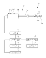
- FIG. 1 is a schematic diagram of an endoscope system
- FIG. 4 is a graph showing spectra of violet light V, blue light B, green light G, and red light R;
- (A) is an explanatory diagram showing a mono-emission mode, and
- (B) is an explanatory diagram showing a multi-emission mode.
- 3 is a block diagram showing functions of an extended processor unit;
- FIG. 10 is an image diagram showing a bleeding site and detection position display circles detected by the detection target detection process;
- FIG. 10 is an image diagram showing a detected position display circle, landmarks detected by landmark detection processing, and a landmark position display circle;
- FIG. 11 is an image diagram showing a display mode of a landmark position display circle of a landmark with a low detection reliability.
- FIG. 10 is an image diagram showing a bleeding site and detection position display circles detected by the detection target detection process
- FIG. 10 is an image diagram showing a detected position display circle, landmarks detected by landmark detection processing, and a landmark position display circle
- FIG. 10 is an explanatory diagram showing a display control process for real positions and a display control process for landmarks;
- FIG. 5 is an explanatory diagram showing display control processing for actual position and display control processing for estimated position;
- FIG. 4 is an explanatory diagram showing a display mode for actual position and a display mode for estimated position;
- (A) is an image diagram showing an actual position display mode, and
- (B) is an image diagram showing an estimated position display mode in which estimated position information is displayed on a sub-screen.
- FIG. 10 is an image diagram showing an estimated position display mode for displaying estimated position information on the main screen;
- FIG. 10 is an explanatory diagram showing that the image of the sub-screen is rotated 180 degrees;
- FIG. 10 is an explanatory diagram showing an estimated position display mode that changes according to the reliability of estimated position information
- FIG. 4 is an explanatory diagram showing start timing and end timing of detection target detection processing and position information estimation processing
- FIG. 9 is an explanatory diagram showing detection of a detection target and landmarks from a second endoscopic image, and display of actual position information of the detection target and position information of landmarks from the first endoscopic image
- FIG. 4 is an explanatory diagram showing a series of flows in a tracking mode
- FIG. 10 is an explanatory diagram for updating landmarks used for position information estimation processing
- the endoscope system 10 has an endoscope 12, a light source device 13, a processor device 14, a display 15, a user interface 16, an expansion processor device 17, and a display 18. .
- the endoscope 12 is optically connected to the light source device 13 and electrically connected to the processor device 14 .
- the light source device 13 supplies illumination light to the endoscope 12 .
- the endoscope 12 is used to illuminate an observation target with illumination light, capture an image of the observation target, and acquire an endoscopic image.
- the endoscope 12 includes an insertion portion 12a to be inserted into the body of an observation target, an operation portion 12b provided at the proximal end portion of the insertion portion 12a, a bending portion 12c provided at the distal end side of the insertion portion 12a, and a distal end portion. and a portion 12d.
- the bending portion 12c bends by operating the operation portion 12b.
- the distal end portion 12d irradiates an observation target with illumination light and receives reflected light from the observation target to capture an image of the observation target.
- the distal end portion 12d is directed in a desired direction by the bending motion of the bending portion 12c.
- the operation unit 12b includes a mode switching switch 12f used for mode switching operation, a still image acquisition instruction switch 12g used for instructing acquisition of a still image to be observed, and a zoom operation unit 12h used for operating the zoom lens 21b. is provided.
- the processor device 14 is electrically connected with the display 15 and the user interface 16 .
- Processor unit 14 receives endoscopic images from endoscope 12 .
- the display 15 outputs and displays an observation target image or information processed by the processor device 14 .
- the user interface 16 has a keyboard, mouse, touch pad, microphone, etc., and has a function of receiving input operations such as function settings.
- Extended processor unit 17 is electrically connected to processor unit 14 .
- the extended processor device 17 receives images or various information from the processor device 14 .
- the display 18 outputs and displays images or information processed by the extended processor device 17 .
- the endoscope system 10 has a mono-emission mode and a multi-emission mode, which are switched by the mode changeover switch 12f.
- the mono light emission mode is a mode in which the observation target is continuously illuminated with illumination light of the same spectrum.
- the multi-light emission mode is a mode in which a plurality of illumination lights with different spectra are switched according to a specific pattern to illuminate the observation target.
- the illumination light includes normal light (broadband light such as white light) used to give brightness to the entire observation object and to observe the entire observation object, or light for emphasizing a specific region of the observation object. This includes special lights used for Also, in the mono light emission mode, the illumination light of a different spectrum may be switched by operating the mode switch 12f. For example, the first illumination light and the second illumination light having different spectra may be switched.
- the mono-emission mode and the multi-emission mode include a tracking mode, and the tracking mode can also be switched with the mode changeover switch 12f.
- tracking mode the actual position information of the detection target is detected and the position information of the detection target is detected so that the user can grasp the position of the detection target, such as a bleeding site, even if the image of the subject, etc., changes. , and the position information of the landmark associated with the position information of the detection target is displayed on the display 18 (or the display 15).
- the illumination light is preferably a combination of violet light V, blue light B, green light G, and red light R.
- the violet light V preferably has a center wavelength of 405 ⁇ 10 nm and a wavelength range of 380 to 420 nm.
- the blue light B preferably has a center wavelength of 450 ⁇ 10 nm and a wavelength range of 420 to 500 nm.
- the green light G preferably has a wavelength range of 480-600 nm.
- the red light R preferably has a central wavelength of 620-630 nm and a wavelength range of 600-650 nm.
- the light source device 13 independently controls the light amounts of the four colors of violet light V, blue light B, green light G, and red light R.
- illumination light L having the same spectrum is continuously emitted for each frame.
- control is performed to change the light amounts of the four colors of violet light V, blue light B, green light G, and red light R according to a specific pattern.
- the specific pattern includes a first emission pattern in which the first illumination light L1 having the first spectrum is emitted continuously for two frames, and a second spectrum different from the first spectrum.
- a frame means that an imaging sensor (not shown) provided at the distal end portion 12d of the endoscope starts receiving reflected light from an observation target, and the output of accumulated charge signals based on the received light is completed. refers to the time between
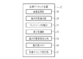
- the extended processor device 17 includes an image acquisition unit 20, a detection target detection unit 21, a landmark processing unit 22, a display control unit 23, an estimated position information calculation unit 24, and a detection memory. 26 and a processing timing setting unit 27 .
- the extended processor device 17 is provided with a program memory for storing programs related to various processes. By executing the above programs by the processor provided in the extended processor device 17, the image acquisition unit 20, the detection target detection unit 21, the landmark processing unit 22, the estimated position information calculation unit 24, and the display control unit 23 , the function of the processing timing setting unit 27 is realized.
- the display control unit 23 may perform display control of the display 15 in addition to the display control of the display 18 .
- the image acquisition unit 20 acquires endoscopic images transmitted from the processor device 14 .
- the processor device 14 transmits the endoscopic image to the extended processor device 17 for each frame.
- the image acquisition unit acquires an endoscopic image for each frame transmitted from the processor device 14 .
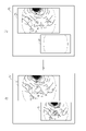
- the detection target detection unit 21 detects the detection target and acquires the real position information of the detection target by performing the detection target detection process on the endoscopic image. As shown in FIG. 5, in the endoscopic image on the display 18, when the bleeding site BS, which is one of the detection targets, is detected by the detection target detection process, display control is performed as the actual position information of the bleeding site BS.
- the unit 23 displays a detection position display circle 30 around the bleeding site BS on the display 18 .
- Detection targets include bleeding sites BS, lesions such as cancer, lesions highlighted by drug fluorescence (PDD (Photodynamic diagnosis)), shapes of specific organs, mucosal patterns, markings after cauterization, and It is preferably at least one of marking (marking given by a pigment, marking given to a swelling agent injected at the time of incision, glitter, or a marker).
- marking marking given by a pigment, marking given to a swelling agent injected at the time of incision, glitter, or a marker.
- the enhancement may become weaker over time and may become difficult to see. It is possible to grasp by
- the detection target detection unit 21 is preferably a learned model that has undergone machine learning using teacher image data that includes the detection target.
- Machine learning includes supervised learning, semi-unsupervised learning, unsupervised learning, reinforcement learning, deep reinforcement learning, learning using neural networks, deep learning, and the like. Further, when detected by the detection target detection process, information on the detected detection target is stored in the detection memory 26 .
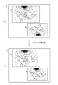
- the landmark processing unit 22 performs landmark detection processing on the endoscopic image to detect the landmark and acquire the position information of the landmark.
- Landmarks include various structures such as blood vessels and duct structures.
- the display control unit 23 A plurality of landmark position display circles 32 are displayed on the display 18 as the position information of the landmarks LM.
- the landmark position display circles 32 can be distinguished from each other.
- each landmark position display circle 32 is given a number NB (distinguishing number) for distinction.
- the landmark LM is detected not only near the detection target such as the bleeding area, but also from a position away from the detection target in order to eliminate factors that reduce the visibility of the detection target, such as pooled blood flowing out from the bleeding site. preferably.
- landmark setting processing is performed to associate the position information of the landmark with the actual position information of the detection target.
- the detection position display circle 30 and the landmark position display circle 32 are linked as a link line. Tie at 34.
- the landmark position display circles having the identification numbers "1", “2", “3”, “4", and "5" around the detected position display circle 30 32 must be connected at least to the detection position indicating circle 30 with a link line 34 . It is also preferable to connect different landmark position display circles 32 with link lines 34 .
- Information about the position information of the landmark LM and the real position information of the detection target associated by the landmark setting process is stored in the detection memory 26 .
- the processing section for performing landmark detection processing in the landmark processing section 22 is preferably a learned model for landmark detection that has been machine-learned using teacher image data including landmarks.
- the landmark processing unit 22 can calculate the reliability of landmark detection, the display mode (color, line style, etc.) of the landmark position information is changed according to the reliability. is preferred. For example, as shown in FIG. 7, when the reliability of the landmark LM with the distinguishing number "1" is lower than the reliability of the other landmarks LM, the landmark with the distinguishing number "1" It is preferable to make the display mode of the landmark position display circle 32 of the LM (dotted line in FIG. 7) different from the display mode of the landmark position display circle 32 of the other landmarks LM (solid line in FIG. 7).
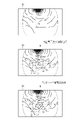
- the display control unit 23 performs a real position display control process for displaying the real position information of the detection target on the display 18 when the detection target is detected, or displays the landmark position information when the detection target is not detected. Any of the display control processing for landmarks to be displayed on the display 18 is performed. As shown in FIG. 8, in the endoscope image on the display 18, the detection position display circle 30 is displayed as the real position information of the detection target by the display control processing for the real position, and the position information of the landmark LM is displayed. A landmark position display circle 32 is displayed. In the actual position display control process, it is preferable to display the link line 34 on the display 18 as well. In FIG. 8, the positional information of the landmark is also displayed in the display control process for the actual position, but the positional information of the landmark may not be displayed.
- the detection target detection unit 21 no longer detects the detection target. Even when the display of the detection target disappears in this manner, the landmark processing unit 22 maintains detection of the landmark if the landmark remains in the endoscopic image.
- the landmark position display circle 32 is displayed on the display 18 as the landmark position information although the detected position display circle 30 is not displayed. be.
- the display control unit 23 performs a real position display control process for displaying the real position information of the detection target on the display 18 in a real position display mode when the detection target is detected, or a display control process for displaying the real position information of the detection target on the display 18 when the detection target is not detected.
- any of the estimated position display control processing may be performed to display the estimated position information of the detection target on the display 18 in an estimated position display mode different from the actual position display mode.
- the estimated position information calculation unit 24 calculates the estimated position information of the detection target.
- the estimated position information calculation unit 24 calculates the estimated position information of the detection target by position information estimation processing based on the endoscopic image. As shown in FIG. 9, when the display of the detection target disappears due to the outflow of the blood puddle BP or the like, the estimated position information calculation unit 24 calculates the estimated position information of the detection target by performing position information estimation processing. do. Then, the display control unit 23 performs the estimated position display control process to display the estimated position display circle 36 as the estimated position information of the detection target in a portion where the detection target is estimated to be located. As a result, when the detection target is the bleeding site BS, the time required for hemostasis can be shortened.
- the position information estimation process preferably calculates estimated position information from within a detection target area including the detection target.
- the blood pool BP is specified as the detection target area, and estimated position information is calculated from within the area of the blood pool BP.
- the feature amount of the endoscopic image such as the color feature amount corresponding to the blood puddle BP).
- the position information estimation process it is preferable to calculate the estimated position information of the detection target from the positional relationship between the landmark position display circles 32, for example, the shape of the link formed from the link lines 34, and the like. In the position information estimation process, it is preferable to calculate the estimated position information of the detection target from the pixel value difference between the endoscopic images obtained at different timings. In the position information estimation process, it is preferable to calculate the estimated position information of the detection target from the optical flow of blood flow in the vicinity of the detection target from the endoscopic image. In addition, it is preferable that the position information estimation process calculates estimated position information of the detection target from the density of blood in the endoscopic image.
- the position information estimation process calculates estimated position information of the detection target from the oxygen saturation calculated from the endoscopic image.
- the estimated position information of the detection target can be calculated using a learned model for landmark detection that has been machine-learned with the teacher image data for obtaining the estimated position information of the detection target. preferable.
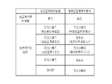
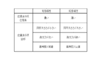
- the actual position display mode for displaying the actual position information of the detection target on the display 18 and the estimated position display mode for displaying the estimated position information of the detection target on the display 18 are the actual position of the detection target and the estimated position. are preferably different in order to facilitate the distinction between As a result, the user can recognize that the estimated position information of the detection target is an estimate, and can grasp that there is a possibility that the information is incorrect.
- the position display color information for the actual position display mode and the position display mode for the estimated position display mode are displayed. It is preferable that the color information for display is different. For example, as shown in FIG. 10, by setting the position display color information for the actual position display mode to "blue" and the position display color information for the estimated position display mode to "green", the user can It becomes easier to distinguish between position information and estimated position information.
- the position display figure of the actual position display mode and the position display figure of the estimated position display mode are different. preferably different.
- the position display graphic is a circle or an ellipse
- the actual position line type and the estimated position line type are different.
- the detected position display circle 30 is represented by a circle with a single line type for actual position
- the estimated position display circle 36 is represented by a circle with a double line type for estimated position. is represented by
- the position display figure is a circle or an ellipse
- the line thickness for the actual position and the line thickness for the estimated position are different.
- the size for the actual position and the size for the estimated position are different.
- the detected position display circle 30 is represented by a circle with a small diameter for the actual position size
- the estimated position display circle 36 is represented by a circle with a large diameter for the estimated position size.
- the position display graphic in the actual position display mode and the position display graphic in the estimated position display mode may have different shapes.
- a circle or an ellipse as the position display figure in the display mode for the actual position
- a polygon such as a rectangle
- the display 18 has a main screen 18a for displaying an endoscopic image and a sub-screen 18b provided at a position different from the main screen 18a, as shown in FIG.
- the detected position display circle 30, which is the actual position information of the detection target is displayed on the main screen 18a. may be displayed on the sub-screen 18b.
- an estimated position display circle 36 is superimposed on the real-time endoscopic image similar to that on the main screen 18a.
- the landmark position display circle 32 is displayed on the main screen 18, but it may not be displayed.
- the landmark position display circle 32 is displayed on the main screen 18 on both the main screen 18a and the sub-screen 18b, but at least one of them may be hidden.
- the display 18 has a main screen 18a for displaying an endoscopic image and a sub-screen 18b provided at a position different from the main screen 18a, as shown in FIG. , the estimated position display circle 36, which is the estimated position information of the detection target, is displayed in the estimated position display mode on the main screen 18a, and the detected position display circle 30, which is the actual position information of the detection target, is displayed in the actual position display mode. may be displayed on the sub-screen 18b. In this case, on the sub-screen 18b, it is preferable to superimpose the detection position display circle 30 on the still image of the endoscope image obtained at the timing when the detection target is detected.
- the landmark position display circle 32 is displayed on the main screen 18 on both the main screen 18a and the sub-screen 18b in FIG. 12, at least one of them may be hidden.
- the vertical and horizontal positions of the real-time endoscopic image on the main screen 18a , and the position in the vertical and horizontal directions of the still image of the endoscopic image on the sub-screen 18b may be different.
- the real-time endoscopic image on the main screen 18a and the still image of the endoscopic image on the sub-screen 18b may be upside down.
- a rotation state detector (not shown) provided in the extended processor unit 17 detects the rotation state from the real-time endoscopic image on the main screen 18a. Then, as shown in FIG.
- an image rotation unit (not shown) provided in the extended processor device 17 rotates the real-time endoscopic image and the vertical direction on the main screen 18a based on the detected rotation state.
- the still image of the endoscopic image on the sub-screen 18b is rotated so that .
- the estimated position information calculation unit 24 calculates the reliability of the estimated position information along with the calculation of the estimated position information. For example, it is preferable to calculate the certainty factor of the estimated position information as the certainty factor of the estimated position information from a machine-learned model.
- the user can select an operation for the observation target according to the reliability of the estimated position information. For example, when the reliability is high, the bleeding site BS is subjected to the hemostasis treatment, whereas when the reliability is low, the hemostasis treatment is not performed so as not to stop bleeding at the wrong site.
- the estimated position information when the estimated position information is represented by the color information for position display, when the reliability of the estimated position information is a certain value or higher, the color information for position display The density is increased, and when the reliability of the estimated position information is low, i.e., less than a certain value, the density of the position display color information is decreased.
- the size of the position display graphic is reduced when the reliability is high, and the size of the position display graphic is increased when the reliability is low. In the case of high reliability, since the range in which the detection target exists can be limited, the size of the position display figure can be reduced.
- the reliability when the reliability is low, the size of the position display figure is increased in order to display as much as possible the range where the detection target may exist.
- the line thickness of the position display figure is thickened, and in the case of low reliability, the line thickness of the position display figure is thinned.
- the line type of the position display graphic is set to a solid line, and when the reliability is low, the line type of the position display graphic is set to a dotted line.
- the start timing or end timing of detection target detection processing and the start timing or end timing of position information estimation processing are preferably set by the processing timing setting unit 27 (see FIG. 4). By setting the start timing and the end timing in this manner so that the detection target detection process or the position information estimation process is not always performed, erroneous detection can be suppressed. In addition, when it is determined that the detection target detection process or the position information estimation process is not necessary, the actual position information and the estimated position information of the detection target can be hidden to make it easier to see other than the detection target such as bleeding points. .
- the start timing of the detection target detection process is the timing at which the endoscope image detects the water supply emitted from the distal end of the endoscope 12 toward the observation target (at the time of water supply detection).
- the detection target detection processing ends when a certain period of time elapses from the timing when the detection target cannot be detected (failure). After a certain period of time has elapsed), etc. are preferable.
- the timing of starting the position information estimation process is, for example, after the detection target detection process fails.
- the end timing of the position information estimation process is preferably the timing when the estimated position information cannot be calculated by the position information estimation process (when the position information estimation process fails). For example, when the position information estimation process fails, information such as landmarks necessary for calculating estimated position information may not be obtained.
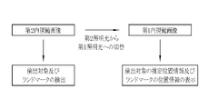
- detection targets and landmarks are detected from the second endoscope image based on the second illumination light, and landmark setting processing is performed. It is preferable to switch from the illumination light to the first illumination light and display the estimated position information of the detection target and the position information of the landmark on the first endoscopic image based on the first illumination light. As a result, when switching from the second illumination light to the first illumination light, the position or area of the detection target is not lost.
- the second illumination light is preferably light suitable for detection of detection targets and landmarks, for example, special light including violet light capable of highlighting structures.
- the first illumination light is preferably light suitable for displaying the estimated position information of the detection target and the position information of the landmark, for example, white light.
- the mode selector switch 12f is operated to turn on the tracking mode. Then, when the start timing of the detection target detection processing set by the processing timing setting unit 27 is satisfied, the detection target detection processing is performed on the endoscopic image. In the detection target detection process, when the detection target including the bleeding site BS is detected, the real position information of the detection target is acquired. The real position information of the detection target is displayed on the display 18 in the real position display mode. Note that when a detection target is detected, landmark position information may also be displayed on the display 18 .
- the estimated position information of the detection target is calculated. It is preferable to calculate the estimated position information based on the position information of the landmark.
- the estimated position information of the detection target is displayed on the display 18 in the estimated position display mode.
- the estimated position display mode is different from the actual position display mode.
- the real position information of the detection target is represented by a single circle, while the estimated position information of the detection target is represented by double circles, thereby distinguishing between the actual position information and the estimated position information. make it easier
- the above series of processes are repeated as long as the tracking mode is ON. Then, when the mode changeover switch 12f is operated to turn off the tracking mode, the detection of the detection target and the like are terminated.
- the endoscope 12 Since the operation of the endoscope 12 is performed manually, even if the estimated position of the detection target is continuously captured in the endoscopic image, the range projected by the endoscopic image changes, and landmarks surrounding the estimated position of the detection target are displayed. If the LM does not fit within the endoscopic image, the organ may be deformed and the relationship between the landmark and the detection target may change. As shown in FIG. 18, when the endoscope 12 captures the next frame, a new landmark LM2 is detected at a position different from the landmark LM used for the position information estimation process, and used for the position information estimation process. The landmark LM may be updated and the display of the estimated position display indicator 36 on the bleeding area BP may be continued.
- FIG. 18A displays the estimated position display indicator 36 in the position information estimation process using the landmark LM.
- a new frame is acquired, as shown in FIG. 18(B), a new landmark LM2 surrounding the estimated position of the detection target is detected in accordance with the movement direction of the previous and next frames, and the new landmark position is displayed.
- indicator 38 is displayed.
- the new landmark LM2 is subjected to a new landmark setting process for associating with the detection target estimated position information, and a new relative relationship is calculated. New relative relationships are indicated by new link lines 39 .
- the new link line 39 is preferably less conspicuous than the link line 34 and preferably uses a dotted line or the like so as not to be confused.
- the number NB (distinguishing number) for distinguishing each landmark position display indicator 32 can also be assigned to the new landmark position display indicator 38, but it is not necessary to assign the number NB if the visibility becomes poor. good. Further, the new landmark position display indicator 38 may have the same or different shape as the landmark position display indicator 32 .
- the endoscope 12 acquires a new frame of the endoscopic image and the landmark LM required for the position information estimation process is not recognized, as shown in FIG. , performs new position information estimation processing based on the new relative relationship, calculates detection target estimated position information, and displays the estimated position display indicator 36 on the display 18 . Since the position information estimation processing based on the landmark LM is finished, the link line 34 is hidden and the new link line 39 is displayed as a solid line like the link line 34 .
- the landmark position display indicator 32 may be displayed immediately after updating the position information estimation process for the landmark LM that is continuously detected, but it is preferable to hide the indicator 32 after a certain period of time has elapsed.
- the new landmark LM2 is the landmark LM
- the new link line 39 is the link line 34
- the new landmark LM2 updates the relative relationship by the new landmark setting processing
- the landmark LM performs the position information estimation processing.
- various processes such as the image acquisition unit 20, the detection target detection unit 21, the landmark processing unit 22, the display control unit 23, the estimated position information calculation unit 24, the detection memory 26, or the processing timing setting unit 27
- the hardware structure of the processing unit that executes is various processors as shown below.
- Various processors include CPU (Central Processing Unit), GPU (Graphical Processing Unit), FPGA (Field Programmable Gate Array), etc.
- Programmable Logic Device which is a processor whose circuit configuration can be changed after manufacturing, and a dedicated electric circuit, which is a processor with a circuit configuration specially designed to execute various processes. .
- One processing unit may be composed of one of these various processors, or a combination of two or more processors of the same or different type (for example, a plurality of FPGAs, a combination of CPU and FPGA, or a combination of CPU and A combination of GPUs, etc.).
- a plurality of processing units may be configured by one processor.
- configuring a plurality of processing units in one processor first, as represented by computers such as clients and servers, one processor is configured by combining one or more CPUs and software, There is a form in which this processor functions as a plurality of processing units.
- SoC System On Chip
- the various processing units are configured using one or more of the above various processors as a hardware structure.
- the hardware structure of these various processors is, more specifically, an electric circuit in the form of a combination of circuit elements such as semiconductor elements.
- the hardware structure of the storage unit is a storage device such as an HDD (hard disc drive) or SSD (solid state drive).
- endoscope system 12 endoscope 12a insertion portion 12b operation portion 12c bending portion 12d tip portion 12f mode changeover switch 12g still image acquisition instruction switch 12h zoom operation portion 13 light source device 14 processor device 15 display 16 user interface 17 extended processor device 18 display 18a main screen 18b subscreen 20 image acquisition unit 21 detection target detection unit 22 landmark processing unit 23 display control unit 24 estimated position information calculation unit 26 detection memory 27 processing timing setting unit 30 detection position display circle 32 landmark Position display circle 34 Link line 36 Estimated position display circle 38 New landmark position display indicator 39 New link line BP Blood pool L Illumination light L1 First illumination light L2 Second illumination light BS Bleeding site LM Landmark LM2 new landmark
Abstract
Description
12 内視鏡
12a 挿入部
12b 操作部
12c 湾曲部
12d 先端部
12f モード切替スイッチ
12g 静止画取得指示スイッチ
12h ズーム操作部
13 光源装置
14 プロセッサ装置
15 ディスプレイ
16 ユーザーインターフェース
17 拡張プロセッサ装置
18 ディスプレイ
18a メイン画面
18b サブ画面
20 画像取得部
21 検出対象検出部
22 ランドマーク処理部
23 表示制御部
24 推定位置情報算出部
26 検出用メモリ
27 処理タイミング設定部
30 検出位置表示用サークル
32 ランドマーク位置表示用サークル
34 リンクライン
36 推定位置表示用サークル
38 新規のランドマーク位置表示用インジケータ
39 新規のリンクライン
BP 血だまり
L 照明光
L1 第1照明光
L2 第2照明光
BS 出血箇所
LM ランドマーク
LM2 新規のランドマーク
10
Claims (14)
- プロセッサを備え、
前記プロセッサが、
内視鏡画像を取得し、
前記内視鏡画像に対して検出対象検出処理を行うことによって、検出対象を検出して前記検出対象の実位置情報を取得し、
前記検出対象が検出されない場合に、前記内視鏡画像に基づく位置情報推定処理によって、前記検出対象の推定位置情報を算出し、
前記検出対象が検出された場合に、前記検出対象の実位置情報を実位置用表示態様でディスプレイに表示する実位置用表示制御処理、又は、前記検出対象が検出されない場合に、前記検出対象の推定位置情報を、前記実位置用表示態様と異なる推定位置用表示態様で前記ディスプレイに表示する推定位置用表示制御処理のいずれかを行う内視鏡システム。 with a processor
the processor
Acquiring endoscopic images,
detecting a detection target and acquiring real position information of the detection target by performing detection target detection processing on the endoscopic image;
calculating estimated position information of the detection target by position information estimation processing based on the endoscopic image when the detection target is not detected;
real position display control processing for displaying the real position information of the detection target on a display in a real position display mode when the detection target is detected; or, when the detection target is not detected, the detection target An endoscope system that performs any one of estimated position display control processing for displaying estimated position information on the display in an estimated position display mode different from the actual position display mode. - 前記検出対象の前記実位置情報と前記推定位置情報の表示のために位置表示用色情報を用いる場合には、前記実位置用表示態様の前記位置表示用色情報と前記推定位置用表示態様の前記位置表示用色情報とが異なっていること、又は、
前記検出対象の前記実位置情報と前記推定位置情報の表示のために位置表示用図形を用いる場合には、前記実位置用表示態様の前記位置表示用図形と前記推定位置用表示態様の前記位置表示用図形とが異なっていること請求項1記載の内視鏡システム。 When position display color information is used to display the actual position information and the estimated position information of the detection target, the position display color information for the actual position display mode and the estimated position display mode being different from the color information for position display, or
When a position display graphic is used to display the actual position information and the estimated position information of the detection target, the position display graphic in the actual position display mode and the position in the estimated position display mode 2. The endoscope system according to claim 1, wherein the graphics for display are different. - 前記位置表示用図形が円又は楕円の場合には、実位置用線種類と推定位置用線種類とが異なっていること、実位置用線太さとが推定位置用線太さとが異なっていること、及び、実位置用大きさと推定位置用大きさとが異なっていることのうち少なくともいずれかである請求項2記載の内視鏡システム。 When the position display figure is a circle or an ellipse, the line type for the actual position is different from the line type for the estimated position, and the line thickness for the actual position is different from the line thickness for the estimated position. 3. The endoscope system according to claim 2, wherein at least one of , and that the size for the actual position and the size for the estimated position are different.
- 前記実位置用表示態様の前記位置表示用図形と前記推定位置用表示態様の前記位置表示用図形の形状とは、それぞれ形状が異なっている請求項2または3記載の内視鏡システム。 The endoscope system according to claim 2 or 3, wherein the position display graphic in the actual position display mode and the position display graphic in the estimated position display mode have different shapes.
- 前記ディスプレイが、前記内視鏡画像を表示するメイン画面、及び、前記メイン画面と異なる位置に設けられたサブ画面を有する場合において、前記推定位置用表示態様として、前記検出対象の推定位置情報を前記サブ画面で表示する請求項1ないし3いずれか1項記載の内視鏡システム。 When the display has a main screen for displaying the endoscopic image, and a sub-screen provided at a position different from the main screen, the estimated position information of the detection target is displayed as the estimated position display mode. The endoscope system according to any one of claims 1 to 3, which is displayed on the sub-screen.
- 前記ディスプレイが、前記内視鏡画像を表示するメイン画面、及び、前記メイン画面と異なる位置に設けられたサブ画面を有する場合において、前記推定位置用表示制御処理によって、前記検出対象の前記推定位置情報を前記推定位置用表示態様で前記メイン画面に表示し、前記検出対象の前記実位置情報を前記実位置用表示態様で前記サブ画面に表示する請求項1ないし3いずれか1項記載の内視鏡システム。 When the display has a main screen for displaying the endoscopic image and a sub-screen provided at a position different from the main screen, the estimated position of the detection target is controlled by the estimated position display control processing. 4. The information according to any one of claims 1 to 3, wherein the information is displayed on the main screen in the display mode for estimated position, and the real position information of the detection target is displayed on the sub-screen in the display mode for actual position. optic system.
- 前記推定位置用表示制御処理は、前記推定位置情報の信頼度に応じて、前記推定位置用表示態様を変化させる請求項1ないし6いずれか1項記載の内視鏡システム。 The endoscope system according to any one of claims 1 to 6, wherein the estimated position display control processing changes the estimated position display mode according to the reliability of the estimated position information.
- 前記位置情報推定処理は、前記検出対象を含む検出対象領域内から、前記推定位置情報を算出する請求項1ないし7いずれか1項記載の内視鏡システム。 The endoscope system according to any one of claims 1 to 7, wherein the position information estimation process calculates the estimated position information from within a detection target area including the detection target.
- 前記プロセッサは、
前記検出対象検出処理の開始タイミング又は終了タイミングと、前記位置情報推定処理の開始タイミング又は終了タイミングとの少なくともいずれかを設定する請求項1ないし8いずれか1項記載の内視鏡システム。 The processor
The endoscope system according to any one of claims 1 to 8, wherein at least one of the start timing or end timing of the detection target detection processing and the start timing or end timing of the position information estimation processing is set. - 前記検出対象には、出血箇所、病変部、特定の臓器の形状、粘膜模様、焼灼後のマーキング、及び、体内に付与したマーキングの少なくともいずれかである請求項1ないし9いずれか1項記載の内視鏡システム。 10. The detection target is at least one of a bleeding site, a lesion, a shape of a specific organ, a mucosal pattern, a marking after cauterization, and a marking applied inside the body. endoscope system.
- プロセッサを備え、
前記プロセッサが、内視鏡画像を取得し、
前記内視鏡画像に対して第1検出処理を行うことによって、検出対象の検出対象実位置情報を取得し、
前記内視鏡画像に対して第2検出処理を行うことによってランドマークの位置情報を取得し、
前記内視鏡画像が更新されて、前記検出対象実位置情報、又は、前記ランドマークの位置情報に基づく位置情報推定処理から得られる検出対象推定位置情報を取得する毎に、前記検出対象推定位置情報又は前記検出対象推定位置情報のいずれかと、前記ランドマークの位置情報とを関連付けて相対関係を設定するランドマーク設定処理を行い、
前記検出対象実位置情報又は前記検出対象推定位置情報をディスプレイに表示する内視鏡システム。 with a processor
the processor acquires an endoscopic image;
Acquiring detection target real position information of a detection target by performing a first detection process on the endoscopic image;
Acquiring landmark position information by performing a second detection process on the endoscopic image;
Whenever the endoscopic image is updated and the actual detection target position information or the estimated detection target position information obtained from position information estimation processing based on the position information of the landmark is acquired, the estimated detection target position perform a landmark setting process for setting a relative relationship by associating either the information or the estimated detection target position information with the position information of the landmark,
An endoscope system that displays the detection target actual position information or the detection target estimated position information on a display. - 前記位置情報推定処理が継続する状態で、新たなフレームの前記内視鏡画像を取得して、新規のランドマークを検出した場合において、前記ランドマーク設定処理として、前記検出対象の推定位置情報と、前記新規のランドマークとを関連付けて新規の相対関係を設定する新規のランドマーク設定処理を行い、
前記新規のランドマーク設定処理の後に、前記位置情報推定処理に必要なランドマークが認識されない場合、前記新規の相対関係に基づく位置情報推定処理を行い、新規の検出対象の推定位置情報を算出し、
前記ディスプレイに前記新規の検出対象の推定位置情報を表示する請求項11記載の内視鏡システム。 When the endoscopic image of a new frame is acquired and a new landmark is detected while the position information estimation process is continuing, the landmark setting process includes the estimated position information of the detection target and , performs a new landmark setting process for setting a new relative relationship by associating with the new landmark,
After the new landmark setting process, if the landmark required for the position information estimation process is not recognized, the position information estimation process based on the new relative relationship is performed to calculate estimated position information of the new detection target. ,
12. The endoscope system according to claim 11, wherein the estimated position information of the new detection target is displayed on the display. - 前記新規のランドマークは、粘膜模様、臓器の形状、ユーザ操作によるマーキングの少なくともいずれかの位置情報である請求項12記載の内視鏡システム。 13. The endoscope system according to claim 12, wherein the new landmark is position information of at least one of mucosal pattern, organ shape, and marking by user operation.
- プロセッサが、
内視鏡画像を取得するステップと、
前記内視鏡画像に対して検出対象検出処理を行うことによって、検出対象を検出して前記検出対象の実位置情報を取得するステップと、
前記検出対象が検出されない場合に、前記内視鏡画像に基づく位置情報推定処理によって、前記検出対象の推定位置情報を算出するステップと、
前記検出対象が検出された場合に、前記検出対象の実位置情報を実位置用表示態様でディスプレイに表示する実位置用表示制御処理、又は、前記検出対象が検出されない場合に、前記検出対象の推定位置情報を、前記実位置用表示態様と異なる推定位置用表示態様で前記ディスプレイに表示する推定位置用表示制御処理のいずれかを行うステップとを有する内視鏡システムの作動方法。
the processor
obtaining an endoscopic image;
a step of detecting a detection target and obtaining real position information of the detection target by performing detection target detection processing on the endoscopic image;
calculating estimated position information of the detection target by position information estimation processing based on the endoscopic image when the detection target is not detected;
real position display control processing for displaying the real position information of the detection target on a display in a real position display mode when the detection target is detected; or, when the detection target is not detected, the detection target and performing any one of estimated position display control processing for displaying estimated position information on the display in an estimated position display mode different from the actual position display mode.
Priority Applications (4)
| Application Number | Priority Date | Filing Date | Title |
|---|---|---|---|
| EP22767085.8A EP4306032A1 (en) | 2021-03-09 | 2022-03-07 | Endoscope system and method for operating same |
| CN202280020353.0A CN116963656A (en) | 2021-03-09 | 2022-03-07 | Endoscope system and working method thereof |
| JP2023505543A JPWO2022191129A1 (en) | 2021-03-09 | 2022-03-07 | |
| US18/463,897 US20230419535A1 (en) | 2021-03-09 | 2023-09-08 | Endoscope system and method of operating the same |
Applications Claiming Priority (2)
| Application Number | Priority Date | Filing Date | Title |
|---|---|---|---|
| JP2021037557 | 2021-03-09 | ||
| JP2021-037557 | 2021-03-09 |
Related Child Applications (1)
| Application Number | Title | Priority Date | Filing Date |
|---|---|---|---|
| US18/463,897 Continuation US20230419535A1 (en) | 2021-03-09 | 2023-09-08 | Endoscope system and method of operating the same |
Publications (1)
| Publication Number | Publication Date |
|---|---|
| WO2022191129A1 true WO2022191129A1 (en) | 2022-09-15 |
Family
ID=83226687
Family Applications (1)
| Application Number | Title | Priority Date | Filing Date |
|---|---|---|---|
| PCT/JP2022/009715 WO2022191129A1 (en) | 2021-03-09 | 2022-03-07 | Endoscope system and method for operating same |
Country Status (5)
| Country | Link |
|---|---|
| US (1) | US20230419535A1 (en) |
| EP (1) | EP4306032A1 (en) |
| JP (1) | JPWO2022191129A1 (en) |
| CN (1) | CN116963656A (en) |
| WO (1) | WO2022191129A1 (en) |
Citations (11)
| Publication number | Priority date | Publication date | Assignee | Title |
|---|---|---|---|---|
| JP2011036371A (en) | 2009-08-10 | 2011-02-24 | Tohoku Otas Kk | Medical image recording apparatus |
| US20150078615A1 (en) * | 2013-09-18 | 2015-03-19 | Cerner Innovation, Inc. | Marking and tracking an area of interest during endoscopy |
| JP2015529489A (en) | 2012-07-25 | 2015-10-08 | インテュイティブ サージカル オペレーションズ, インコーポレイテッド | Efficient and interactive bleeding detection in surgical systems |
| WO2018216188A1 (en) * | 2017-05-26 | 2018-11-29 | オリンパス株式会社 | Endoscopic image processing apparatus and endoscopic image processing method |
| WO2019106712A1 (en) * | 2017-11-28 | 2019-06-06 | オリンパス株式会社 | Endoscope image processing device and endoscope image processing method |
| WO2019146066A1 (en) * | 2018-01-26 | 2019-08-01 | オリンパス株式会社 | Endoscope image processing device, endoscope image processing method, and program |
| WO2019202827A1 (en) | 2018-04-17 | 2019-10-24 | ソニー株式会社 | Image processing system, image processing device, image processing method, and program |
| WO2019244255A1 (en) * | 2018-06-19 | 2019-12-26 | オリンパス株式会社 | Endoscope image processing device and endoscope image processing method |
| WO2020040087A1 (en) * | 2018-08-20 | 2020-02-27 | 富士フイルム株式会社 | Medical image processing system |
| WO2020054604A1 (en) * | 2018-09-11 | 2020-03-19 | 日本電気株式会社 | Information processing device, control method, and program |
| WO2020183936A1 (en) * | 2019-03-12 | 2020-09-17 | 日本電気株式会社 | Inspection device, inspection method, and storage medium |
-
2022
- 2022-03-07 WO PCT/JP2022/009715 patent/WO2022191129A1/en active Application Filing
- 2022-03-07 CN CN202280020353.0A patent/CN116963656A/en active Pending
- 2022-03-07 JP JP2023505543A patent/JPWO2022191129A1/ja active Pending
- 2022-03-07 EP EP22767085.8A patent/EP4306032A1/en active Pending
-
2023
- 2023-09-08 US US18/463,897 patent/US20230419535A1/en active Pending
Patent Citations (11)
| Publication number | Priority date | Publication date | Assignee | Title |
|---|---|---|---|---|
| JP2011036371A (en) | 2009-08-10 | 2011-02-24 | Tohoku Otas Kk | Medical image recording apparatus |
| JP2015529489A (en) | 2012-07-25 | 2015-10-08 | インテュイティブ サージカル オペレーションズ, インコーポレイテッド | Efficient and interactive bleeding detection in surgical systems |
| US20150078615A1 (en) * | 2013-09-18 | 2015-03-19 | Cerner Innovation, Inc. | Marking and tracking an area of interest during endoscopy |
| WO2018216188A1 (en) * | 2017-05-26 | 2018-11-29 | オリンパス株式会社 | Endoscopic image processing apparatus and endoscopic image processing method |
| WO2019106712A1 (en) * | 2017-11-28 | 2019-06-06 | オリンパス株式会社 | Endoscope image processing device and endoscope image processing method |
| WO2019146066A1 (en) * | 2018-01-26 | 2019-08-01 | オリンパス株式会社 | Endoscope image processing device, endoscope image processing method, and program |
| WO2019202827A1 (en) | 2018-04-17 | 2019-10-24 | ソニー株式会社 | Image processing system, image processing device, image processing method, and program |
| WO2019244255A1 (en) * | 2018-06-19 | 2019-12-26 | オリンパス株式会社 | Endoscope image processing device and endoscope image processing method |
| WO2020040087A1 (en) * | 2018-08-20 | 2020-02-27 | 富士フイルム株式会社 | Medical image processing system |
| WO2020054604A1 (en) * | 2018-09-11 | 2020-03-19 | 日本電気株式会社 | Information processing device, control method, and program |
| WO2020183936A1 (en) * | 2019-03-12 | 2020-09-17 | 日本電気株式会社 | Inspection device, inspection method, and storage medium |
Also Published As
| Publication number | Publication date |
|---|---|
| CN116963656A (en) | 2023-10-27 |
| EP4306032A1 (en) | 2024-01-17 |
| JPWO2022191129A1 (en) | 2022-09-15 |
| US20230419535A1 (en) | 2023-12-28 |
Similar Documents
| Publication | Publication Date | Title |
|---|---|---|
| US20180125333A1 (en) | Efficient and interactive bleeding detection in a surgical system | |
| JPWO2018159363A1 (en) | Endoscope system and operation method thereof | |
| US9723971B2 (en) | Image processing apparatus, method, and program | |
| JP7060536B2 (en) | Endoscopic image processing device, operation method and program of endoscopic image processing device, endoscopic system | |
| US9824445B2 (en) | Endoscope system | |
| JP5580758B2 (en) | Fluorescence observation equipment | |
| US20210153720A1 (en) | Medical image processing apparatus, endoscope system, and method for operating medical image processing apparatus | |
| JP7125479B2 (en) | MEDICAL IMAGE PROCESSING APPARATUS, METHOD OF OPERATION OF MEDICAL IMAGE PROCESSING APPARATUS, AND ENDOSCOPE SYSTEM | |
| JP7315576B2 (en) | Medical image processing device, operating method and program for medical image processing device, diagnostic support device, and endoscope system | |
| JP2008054763A (en) | Medical image diagnostic apparatus | |
| JP7389257B2 (en) | Endoscope system and its operating method | |
| JP2022071617A (en) | Endoscope system and endoscope device | |
| WO2022191129A1 (en) | Endoscope system and method for operating same | |
| WO2022190740A1 (en) | Endoscope system and method for operating same | |
| WO2022191128A1 (en) | Endoscope system and method for operating same | |
| JP7146318B1 (en) | Computer program, learning model generation method, and surgery support device | |
| US20220414885A1 (en) | Endoscope system, medical image processing device, and operation method therefor | |
| EP4111938A1 (en) | Endoscope system, medical image processing device, and operation method therefor | |
| JP7391113B2 (en) | Learning medical image data creation device, learning medical image data creation method, and program | |
| US20220409010A1 (en) | Medical image processing device, operation method therefor, and endoscope system | |
| JP2023007331A (en) | Endoscope system, medical image processing device, and operation method therefor |
Legal Events
| Date | Code | Title | Description |
|---|---|---|---|
| 121 | Ep: the epo has been informed by wipo that ep was designated in this application |
Ref document number: 22767085 Country of ref document: EP Kind code of ref document: A1 |
|
| WWE | Wipo information: entry into national phase |
Ref document number: 2023505543 Country of ref document: JP |
|
| WWE | Wipo information: entry into national phase |
Ref document number: 202280020353.0 Country of ref document: CN |
|
| WWE | Wipo information: entry into national phase |
Ref document number: 2022767085 Country of ref document: EP |
|
| NENP | Non-entry into the national phase |
Ref country code: DE |
|
| ENP | Entry into the national phase |
Ref document number: 2022767085 Country of ref document: EP Effective date: 20231009 |