WO2021193932A1 - 静電容量センサ、センサユニット、およびロボット - Google Patents
静電容量センサ、センサユニット、およびロボット Download PDFInfo
- Publication number
- WO2021193932A1 WO2021193932A1 PCT/JP2021/012929 JP2021012929W WO2021193932A1 WO 2021193932 A1 WO2021193932 A1 WO 2021193932A1 JP 2021012929 W JP2021012929 W JP 2021012929W WO 2021193932 A1 WO2021193932 A1 WO 2021193932A1
- Authority
- WO
- WIPO (PCT)
- Prior art keywords
- capacitance
- sensor
- electrode
- unit
- robot
- Prior art date
- Legal status (The legal status is an assumption and is not a legal conclusion. Google has not performed a legal analysis and makes no representation as to the accuracy of the status listed.)
- Ceased
Links
Images



Classifications
-
- B—PERFORMING OPERATIONS; TRANSPORTING
- B25—HAND TOOLS; PORTABLE POWER-DRIVEN TOOLS; MANIPULATORS
- B25J—MANIPULATORS; CHAMBERS PROVIDED WITH MANIPULATION DEVICES
- B25J19/00—Accessories fitted to manipulators, e.g. for monitoring, for viewing; Safety devices combined with or specially adapted for use in connection with manipulators
- B25J19/02—Sensing devices
-
- G—PHYSICS
- G01—MEASURING; TESTING
- G01B—MEASURING LENGTH, THICKNESS OR SIMILAR LINEAR DIMENSIONS; MEASURING ANGLES; MEASURING AREAS; MEASURING IRREGULARITIES OF SURFACES OR CONTOURS
- G01B7/00—Measuring arrangements characterised by the use of electric or magnetic techniques
-
- G—PHYSICS
- G06—COMPUTING OR CALCULATING; COUNTING
- G06F—ELECTRIC DIGITAL DATA PROCESSING
- G06F3/00—Input arrangements for transferring data to be processed into a form capable of being handled by the computer; Output arrangements for transferring data from processing unit to output unit, e.g. interface arrangements
- G06F3/01—Input arrangements or combined input and output arrangements for interaction between user and computer
- G06F3/03—Arrangements for converting the position or the displacement of a member into a coded form
- G06F3/041—Digitisers, e.g. for touch screens or touch pads, characterised by the transducing means
Definitions
- the present invention relates to a capacitance sensor that detects the approach and / or contact of a detection object, a sensor unit having the capacitance sensor, and a robot having the sensor unit.
- robots that perform predetermined work according to a predetermined program have been put into practical use.
- the position of at least a part of the housing may change as the work is performed.
- Patent Document 1 discloses that the contact force when a robot and an operator come into contact with each other is detected with high accuracy.
- a method of arranging a capacitance sensor for detecting the approach and / or contact of the detection object on the surface of the robot housing can be considered. ..
- sensors are often oriented toward miniaturization and thinning. Therefore, in order to detect the approach and / or contact of an object to be detected in a wide range on the surface of the housing, a small sensor is used in the housing. It is necessary to arrange multiple sheets side by side on the surface.
- the processing speed of the measuring unit that measures the output values from a plurality of sensors in parallel is lower than that in the case of measuring only the output values from one sensor. Therefore, as the area of the housing surface covered by the sensor increases, the load on the measuring unit increases, which may cause a problem that the processing speed decreases. When the processing speed of the measuring unit is reduced, it becomes difficult to detect the approach and / or contact of the operator, so that it becomes difficult for the operator to stop the movement of the robot before it hits the housing of the robot.
- the present invention can suitably detect the approach and / or contact between the robot housing and the worker, and even if the housing and the worker come into contact with each other, the impact due to the contact is preferably detected. It is an object of the present invention to provide a capacitive sensor, a sensor unit, and a robot that can reduce the capacitance.
- the capacitance sensor of the present invention includes a first electrode, a second electrode arranged to face the first electrode, and the first electrode and the second electrode. It is a dielectric material arranged between the two, and has a shock absorbing portion for absorbing a shock applied from the first electrode side.
- the sensor unit of the present invention has a first capacitance between the capacitance sensor, the first electrode and an object to be detected, and / or a second electrode between the first electrode and the second electrode. (2) It has a capacitance measuring unit for measuring capacitance.
- the robot of the present invention has a first capacitance between the capacitance sensor and the first electrode and an object to be detected, and / or a second electrode between the first electrode and the second electrode. It has a capacitance measuring unit for measuring capacitance and a robot housing on which the capacitance sensor is arranged on the surface.
- the robot of the present invention has the sensor unit and a robot housing in which the capacitance sensor of the sensor unit is arranged on the surface.
- the approach and / or contact between the robot housing and the worker can be suitably detected, and even if the housing and the worker come into contact with each other, the impact due to the contact can be suitably reduced.
- the figure for demonstrating the capacitance sensor which concerns on this invention.
- the figure for demonstrating the sensor unit which has a capacitance sensor.
- the figure for demonstrating the case where a sensor unit operates as a proximity sensor.
- the figure for demonstrating the case where a sensor unit operates as a contact sensor.
- the figure for demonstrating the robot which has a sensor unit.
- the figure for demonstrating the case where a shock absorbing layer has a void.
- the figure for demonstrating the case where a shock absorbing layer has a void.
- the figure for demonstrating the case where a shock absorbing layer has a void.
- the figure for demonstrating the case where a shock absorbing layer has a void.
- each configuration of the embodiment can be variously modified and implemented without departing from the gist thereof. Further, each configuration of the embodiment can be selected as needed or can be combined as appropriate.
- FIG. 1 is a diagram for explaining the capacitance sensor 1 according to the present invention.
- FIG. 1 shows a cross section of the capacitance sensor 1.
- the capacitance sensor 1 has an upper electrode 11, a shock absorbing layer 12, and a lower electrode 13.
- the upper electrode 11 is an example of the first electrode of the present invention.
- the shock absorbing layer 12 is an example of the shock absorbing portion of the present invention.
- the lower electrode 13 is an example of the second electrode of the present invention.
- the vertical direction of the capacitance sensor 1 will be described with the upper electrode 11 side as the upper side and the lower electrode 13 side as the lower side.
- the capacitance sensor 1 will be described in detail later, but is a proximity sensor that detects the approach of the detection object and / or a contact that detects that the detection object has come into contact with the capacitance sensor 1 from the upper electrode 11 side. Operates as a sensor. Although not shown in FIG. 1, the upper surface of the upper electrode 11 is not exposed and is covered with an appropriate cover material or the like that does not affect the detection performance of the capacitance sensor 1. It is preferable that it is covered.
- the impact absorbing layer 12 is a dielectric material having a relatively low relative permittivity, is relatively soft, and is made of a material capable of absorbing impact.
- the shock absorbing layer 12 is made of a resin foam. More specifically, as the resin forming the shock absorbing layer 12, polyurethane (PU), ethylene propylene diene rubber (EPDM), or polyethylene, polypropylene, ethylene vinyl acetate copolymer, silicon, polyvinyl chloride, polyimide, fluororubber Etc. can be used.
- the relative permittivity of the polyurethane foam is about 1.1 or more and 2.0 or less, preferably 1.1 or more and 1.8 or less, and more preferably 1.1 or more and 1.5 or less.
- the shock absorbing layer 12 can absorb and soften the shock when the detection object hits the capacitance sensor 1 from the upper electrode 11 side.
- the shock absorbing layer 12 preferably has a certain thickness or more in order to secure the performance of absorbing the shock.
- the shock absorbing layer 12 has a thickness of 1 mm or more and 30 mm or less. In this embodiment, the case where the shock absorbing layer 12 has a thickness of 10 mm will be described.
- the Asker C hardness of the shock absorbing layer 12 is 0 or more and 80 or less, preferably 1 or more and 60 or less, and more preferably 5 or more and 40 or less.
- the foam density is 50 kg / m3 or more and 500 kg / m3 or less, preferably 80 kg / m3 or more and 450 kg / m3 or less, and more preferably 100 kg / m3. More than 400 kg / m3 or less.
- the capacitance sensor 1 according to the present invention includes a shock absorbing layer 12 between the upper electrode 11 and the lower electrode 13 having a thickness sufficient to absorb the shock applied from the upper electrode 11 side. It has the feature. Details of the effects that the capacitance sensor 1 according to the present invention can exert due to such features will be described later.
- FIG. 2 is a diagram for explaining a sensor unit 2 having a capacitance sensor 1.
- the sensor unit 2 includes a capacitance sensor 1, changeover switches 20 and 21, a capacitance measuring unit 22, and a detecting unit 23.
- the changeover switches 20 and 21, the capacitance measuring unit 22, and the detecting unit 23 are collectively referred to as a sensor control unit 24.
- the capacitance measuring unit 22 is connected to the upper electrode 11 and the lower electrode 13 of the capacitance sensor 1 via changeover switches 20 and 21.
- the changeover switches 20 and 21 are switches for switching the operation of the capacitance sensor 1.
- the capacitance sensor 1 operates as a proximity sensor that detects an object to be detected approaching the upper electrode 11 or a contact sensor that detects that the object to be detected has come into contact with the upper electrode 11. ..
- the state in which the operation of the capacitance sensor 1 is switched to the proximity sensor by the changeover switches 20 and 21 is described as the changeover switches 20 and 21 being switched to the proximity side.
- the state in which the operation of the capacitance sensor 1 is switched to the contact sensor by the changeover switches 20 and 21 is described as the changeover switches 20 and 21 being switched to the contact side.
- the changeover switch 20 is a switch that connects the upper electrode 11 to either the capacitance measuring unit 22 or the ground.
- the changeover switch 21 is a switch that connects the lower electrode 13 to either the capacitance measuring unit 22 or the power supply unit 30 that supplies a predetermined AC voltage (see FIGS. 3A and 3B described later).
- the changeover switch 20 connects the upper electrode 11 to the capacitance measuring unit 22, and the changeover switch 21 connects the lower electrode 13 to the power supply unit 30.
- the changeover switch 20 and 21 are switched to the contact side, the changeover switch 20 connects the upper electrode 11 to the ground, and the changeover switch 21 connects the lower electrode 13 to the capacitance measuring unit 22.
- the capacitance measuring unit 22 has a first capacitance, which is the capacitance between the upper electrode 11 and the object to be detected, or the upper electrode 11 and the lower electrode, depending on the switching destinations of the changeover switches 20 and 21.
- the second capacitance which is the capacitance between them, is measured.
- the detection unit 23 detects that the detection target has approached the upper electrode 11 based on the first capacitance measured by the capacitance measurement unit 22.
- the detection unit 23 detects that the detection object has come into contact with the upper electrode 11 based on the second capacitance measured by the capacitance measurement unit 22. do.
- FIG. 3A is a diagram for explaining a case where the sensor unit 2 operates as a proximity sensor.
- the sensor control unit 24 (changeover switches 20 and 21, capacitance measurement unit 22, and detection unit 23) is not shown.
- the lower electrode 13 is connected to the power supply unit 30 as described above.
- the upper electrode 11 is connected to the power supply unit 30 having the same potential and the same phase as the power supply unit 30.
- the power supply unit 30 to which the upper electrode 11 is connected and the power supply unit 30 to which the lower electrode 13 is connected may be different power supply units or may be the same power supply unit.
- the first capacitance between the detection target and the upper electrode 11 changes according to the change in the distance between the detection target and the upper electrode 11. Therefore, by measuring the change in the first capacitance with the capacitance measuring unit 22, it is possible to detect that the object to be detected has approached the upper electrode 11.
- FIG. 3B is a diagram for explaining a case where the sensor unit 2 operates as a contact sensor. Also in FIG. 3B, for the sake of explanation, the changeover switches 20 and 21, the capacitance measuring unit 22, and the detecting unit 23 are not shown.
- the upper electrode 11 is connected to the ground as described above. Further, as described above, the lower electrode 13 is connected to the power supply unit 30.
- the upper electrode 11 When the upper electrode 11 is connected to the ground in this way, a potential difference is generated between the upper electrode 11 and the lower electrode 13, and a current flows.
- the upper electrode 11 and the shock absorbing layer 12 bend, and the distance between the upper electrode 11 and the lower electrode 13 changes, the upper electrode 11 and the lower electrode 13 change according to the amount of change.
- the operation of the sensor unit 2 as a proximity sensor and the operation as a contact sensor can be switched by the changeover switches 20 and 21.
- the changeover switches 20 and 21 at high speed (for example, 10 kHz) at predetermined minute time intervals, the sensor unit 2 can perform the operation as a proximity sensor and the operation as a contact sensor at the same time in a pseudo manner. can.
- FIG. 4 is a diagram for explaining the robot 3 having the sensor unit 2.
- the robot 3 includes a sensor unit 2, a housing 31, a robot control unit 32, and a motor 33.
- the robot 3 is installed in a factory, for example, and performs preset predetermined work based on a preset program. In the present embodiment, it is assumed that the robot 3 shares a space with a human being (hereinafter referred to as a worker) and performs each work.
- a human being hereinafter referred to as a worker
- the housing 31 is the housing of the robot 3. Although one housing 31 is shown in FIG. 4, the housing 31 may be an aggregate of a plurality of housings.
- the robot 3 performs a predetermined work based on the control of the robot control unit 32. During this operation, at least a part of the housing 31 moves along a predetermined trajectory set in advance or within a predetermined range.
- the robot 3 and the worker are working in the same space, and depending on the movement of the robot 3 or the worker, the robot 3 and the worker may approach or come into contact with each other.
- the capacitance sensor 1 is provided on at least a part of the surface of the housing 31, and the sensor unit 2 detects this approach or contact. Although the capacitance sensor 1 is provided on the entire surface of the housing 31 in FIG. 4, for example, the capacitance sensor 1 may be provided only in a portion where the operator may approach or come into contact with the operator. ..
- the robot control unit 32 reads, for example, a robot operation program for executing the instruction from a memory (not shown) according to an instruction input from an input unit (not shown), and controls the motor 33 based on the program.
- the robot 3 performs a predetermined work and / or movement by using the power generated by the motor 33 under the control of the robot control unit 32.
- the robot control unit 32 can stop the movement of the housing 31 by the motor 33.
- the robot control unit 32 stops the movement of the housing 31 by the motor 33 when, for example, the sensor unit 2 detects that the operator is approaching the housing 31.
- the robot control unit 32 stops the movement of the housing 31 by the motor 33 when, for example, the sensor unit 2 detects contact. By such an operation, the impact caused by the housing 31 of the robot 3 hitting the operator is reduced.
- the capacitance sensor 1 has a shock absorbing layer 12 capable of absorbing a shock. Therefore, even if the housing 31 hits the operator, the impact is reduced by the shock absorbing layer 12 of the capacitance sensor 1 arranged on the surface of the housing 31.
- the capacitance sensor 1 is a dielectric material having a relatively low dielectric constant between the upper electrode 11 and the lower electrode 13, and is relatively soft.
- the shock absorbing layer 12 made of a material capable of absorbing shock is arranged (see FIG. 1).
- C ⁇ 0 ⁇ rS / d (1)
- S is the area of the capacitance sensor
- d is the distance between the upper electrode and the lower electrode (that is, the thickness of the dielectric)
- ⁇ 0 is the relative permittivity of vacuum
- ⁇ r is the relative permittivity of the dielectric.
- the change in capacitance between the upper electrode and the lower electrode is measured when the capacitance sensor operates as a contact sensor. That is, according to the equation (1), in order to increase the area of the sensor while maintaining the sensitivity as a contact sensor, the relative permittivity of the dielectric may be reduced and the thickness may be increased.
- the shock absorbing layer 12 as a dielectric is formed of a polyurethane foam having a thickness of 10 mm (relative permittivity of about 1.1 or more and 2.0 or less) or the like.
- the area per sensor can be increased in the capacitance sensor 1 according to the present invention as compared with, for example, a thin conventional capacitance sensor.
- a conventional thin capacitance sensor having a urethane gel with a thickness of 2 mm (relative permittivity of about 3.0) as a dielectric, and a capacitance sensor 1 according to the present invention (thickness of the shock absorbing layer 12 is 10 mm).
- the capacitance sensor 1 according to the present invention has a thickness of 5 times and a relative permittivity of about 1/2 times. Therefore, in the capacitance sensor 1 according to the present invention, the area can be increased to about 10 times that of the thin capacitance sensor while maintaining the same sensor sensitivity as the conventional thin capacitance sensor (formula). See (1)).
- a relatively thick dielectric (shock absorbing layer 12) having a relatively low relative permittivity is arranged between the upper electrode 11 and the lower electrode 13. , It is possible to realize a large area without lowering the sensitivity of the sensor.
- the capacitance sensor 1 of the present invention can cover a large area with one sensor, it covers the entire surface of the robot housing with a smaller number of sheets as compared with the conventional small capacitance sensor. be able to. Therefore, the number of output values processed in parallel by the capacitance measuring unit 22 (see FIG. 2) that processes the output value of the capacitance sensor 1 can be reduced. As a result, the processing speed can be increased as compared with the conventional small capacitance sensor.
- the capacitance sensor 1 of the present invention has a large area of one sensor, the processing strength and the mechanical strength per sensor are higher than those in the case where a plurality of conventional small capacitance sensors are arranged side by side. improves. Therefore, the life of the capacitance sensor 1 is extended, and the installation cost is reduced.
- the shock absorbing layer 12 arranged between the upper electrode 11 and the lower electrode 13 is a foam of a resin such as polyurethane, and is soft and capable of absorbing shock. It is made of material. As a result, even if the housing of the robot collides with the body of the worker who is the object to be detected, the impact given from the housing to the body of the worker is reduced.
- the shock absorbing layer 12 is arranged between the upper electrode 11 and the lower electrode 13, the shock absorbing layer 12 does not have an adverse effect when the upper electrode 11 operates as a proximity sensor. Therefore, in the capacitance sensor 1 of the present invention, it is possible to reduce the impact given to the operator's body from the housing of the robot without lowering the sensitivity as the proximity sensor.
- the capacitance sensor 1 of the present invention has better contact detection sensitivity than, for example, a method of detecting contact between a housing and an operator by a torque sensor inside a robot or a motor current. Therefore, it is highly safe. Further, the safety can be further improved by using the method of detecting the contact between the housing and the operator by the torque sensor or the motor current inside the robot and the capacitance sensor of the present invention in combination.
- the thickness of the shock absorbing layer 12 is set to 10 mm, but this is an example.
- the thickness of the shock absorbing layer may be set to, for example, 1 mm or more and 30 mm or less. can.
- the thickness of the shock absorbing layer may be appropriately set within the above range depending on the balance between the desired sensor area and the ability of the shock absorbing layer to absorb the shock.
- the shock absorbing layer 12 is formed of a uniform foam, but may have voids having a predetermined shape in order to further enhance the shock absorbing property.
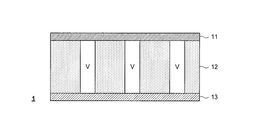
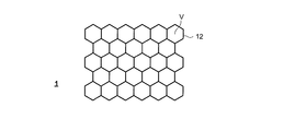
- 5A to 5C are diagrams for explaining the case where the shock absorbing layer has voids.
- FIG. 5A is a diagram showing an example in which the shape of the void V in the cross section of the shock absorbing layer 12 is substantially rectangular.
- FIG. 5B is a diagram showing an example in which the shape of the void V in the cross section of the shock absorbing layer 12 is elliptical.
- the size of the voids is not limited to the examples shown in FIGS. 5A and 5B, and for example, the proportion of the voids in the shock absorbing layer 12 may be larger. That is, for example, the foam constituting the shock absorbing layer 12 may be formed in a thin columnar shape, and all other regions may be voids.
- FIG. 5C shows an example in which the foam constituting the shock absorbing layer 12 has a honeycomb structure.
- FIG. 5C is a cross-sectional view of the shock absorbing layer 12 having a honeycomb structure in a plane perpendicular to the thickness direction. In this case, a gap V exists between the foams constituting the honeycomb structure.
- a structure in which regular hexagonal voids are arranged is referred to as a honeycomb structure, but a structure in which three-dimensional figures having the same shape other than the regular hexagon are arranged may be adopted.
- the present invention is suitably used as a capacitance sensor arranged in a housing of a robot that cooperates in the same space as an operator.
- Capacitance sensor 2 Sensor unit 3 Robot 11 Upper electrode 12 Shock absorption layer 13 Lower electrode 20, 21 Changeover switch 22 Capacity measurement unit 23 Detection unit 24 Sensor control unit 30 Power supply unit 31 Housing 32 Robot control unit 33 Motor
Landscapes
- Engineering & Computer Science (AREA)
- Physics & Mathematics (AREA)
- General Physics & Mathematics (AREA)
- General Engineering & Computer Science (AREA)
- Theoretical Computer Science (AREA)
- Human Computer Interaction (AREA)
- Robotics (AREA)
- Mechanical Engineering (AREA)
- Manipulator (AREA)
Priority Applications (1)
| Application Number | Priority Date | Filing Date | Title |
|---|---|---|---|
| JP2022510747A JPWO2021193932A1 (https=) | 2020-03-27 | 2021-03-26 |
Applications Claiming Priority (2)
| Application Number | Priority Date | Filing Date | Title |
|---|---|---|---|
| JP2020058509 | 2020-03-27 | ||
| JP2020-058509 | 2020-03-27 |
Publications (1)
| Publication Number | Publication Date |
|---|---|
| WO2021193932A1 true WO2021193932A1 (ja) | 2021-09-30 |
Family
ID=77890335
Family Applications (1)
| Application Number | Title | Priority Date | Filing Date |
|---|---|---|---|
| PCT/JP2021/012929 Ceased WO2021193932A1 (ja) | 2020-03-27 | 2021-03-26 | 静電容量センサ、センサユニット、およびロボット |
Country Status (2)
| Country | Link |
|---|---|
| JP (1) | JPWO2021193932A1 (https=) |
| WO (1) | WO2021193932A1 (https=) |
Citations (2)
| Publication number | Priority date | Publication date | Assignee | Title |
|---|---|---|---|---|
| JP2019149207A (ja) * | 2015-03-02 | 2019-09-05 | 学校法人福岡大学 | 近接・接触センサ |
| WO2019187388A1 (ja) * | 2018-03-26 | 2019-10-03 | 日東電工株式会社 | 発泡シート |
Family Cites Families (5)
| Publication number | Priority date | Publication date | Assignee | Title |
|---|---|---|---|---|
| JP2008241717A (ja) * | 2004-03-29 | 2008-10-09 | Sanyo Electric Co Ltd | 静電容量型圧力センサー及びこれを用いた心拍/呼吸計測装置 |
| JP2008155711A (ja) * | 2006-12-21 | 2008-07-10 | Toyoda Gosei Co Ltd | 後突用エアバッグ装置 |
| JP5811588B2 (ja) * | 2011-05-18 | 2015-11-11 | 国立大学法人佐賀大学 | 複合センサ |
| JP2018155711A (ja) * | 2017-03-21 | 2018-10-04 | 住友理工株式会社 | センサ装置 |
| JP7055334B2 (ja) * | 2017-11-21 | 2022-04-18 | 積水ポリマテック株式会社 | 静電容量センサおよび静電容量センサ装置、並びに静電容量センサの制御方法 |
-
2021
- 2021-03-26 WO PCT/JP2021/012929 patent/WO2021193932A1/ja not_active Ceased
- 2021-03-26 JP JP2022510747A patent/JPWO2021193932A1/ja active Pending
Patent Citations (2)
| Publication number | Priority date | Publication date | Assignee | Title |
|---|---|---|---|---|
| JP2019149207A (ja) * | 2015-03-02 | 2019-09-05 | 学校法人福岡大学 | 近接・接触センサ |
| WO2019187388A1 (ja) * | 2018-03-26 | 2019-10-03 | 日東電工株式会社 | 発泡シート |
Non-Patent Citations (1)
| Title |
|---|
| TSUJI, SATOSHI ET AL.: "Development of a Proximity and Tactile Sensor for Human Collaboration Robot", LECTURE PROCEEDINGS OF 2016 ROBOTICS AND MECHATRONICS CONFERENCE, 8 June 2016 (2016-06-08) * |
Also Published As
| Publication number | Publication date |
|---|---|
| JPWO2021193932A1 (https=) | 2021-09-30 |
Similar Documents
| Publication | Publication Date | Title |
|---|---|---|
| JP6703728B2 (ja) | 近接触覚センサ | |
| CN107433587B (zh) | 机器人 | |
| KR101380269B1 (ko) | 자율 이동 장치 | |
| US11104006B2 (en) | Contact sensors for a mobile robot | |
| JP2019000930A (ja) | 安全装置 | |
| US8950792B2 (en) | Compliant solid-state bumper for robot | |
| CN106103204B (zh) | 车辆移动状态判定设备和车辆移动控制设备 | |
| CN105313142B (zh) | 移动式人机协调型机器人 | |
| ES2233717T3 (es) | Estructuras de revestimiento inteligente. | |
| CN104742155A (zh) | 具有保护部件的人协调型工业用机器人 | |
| CN105690383A (zh) | 人机协调机器人系统 | |
| JP2009527765A (ja) | 容量タッチパッド技術を用いて、ロボット把持メカニズムに接触感覚を得させるシステム | |
| CN110168333A (zh) | 传感器装置 | |
| CN108602194B (zh) | 作业机器人 | |
| WO2018173366A1 (ja) | センサ装置 | |
| KR100661330B1 (ko) | 레그식 이동 로봇 | |
| WO2021193932A1 (ja) | 静電容量センサ、センサユニット、およびロボット | |
| JP5305082B2 (ja) | 自律移動装置 | |
| JP2020055045A (ja) | ロボットセンサ | |
| Zhang et al. | Design and analysis of a collision detector for hybrid robotic machine tools | |
| CN100416248C (zh) | 运动碰撞接触感知装置 | |
| JP5517422B2 (ja) | 自律移動装置 | |
| CN110861124B (zh) | 一种机械臂作业状态下安全防碰系统 | |
| JP6776599B2 (ja) | エレベータ装置 | |
| KR101952020B1 (ko) | 면진을 이용한 면진 발전기 |
Legal Events
| Date | Code | Title | Description |
|---|---|---|---|
| 121 | Ep: the epo has been informed by wipo that ep was designated in this application |
Ref document number: 21777096 Country of ref document: EP Kind code of ref document: A1 |
|
| ENP | Entry into the national phase |
Ref document number: 2022510747 Country of ref document: JP Kind code of ref document: A |
|
| NENP | Non-entry into the national phase |
Ref country code: DE |
|
| 122 | Ep: pct application non-entry in european phase |
Ref document number: 21777096 Country of ref document: EP Kind code of ref document: A1 |