WO2021193873A1 - Dispositif de valve mitrale artificielle - Google Patents
Dispositif de valve mitrale artificielle Download PDFInfo
- Publication number
- WO2021193873A1 WO2021193873A1 PCT/JP2021/012728 JP2021012728W WO2021193873A1 WO 2021193873 A1 WO2021193873 A1 WO 2021193873A1 JP 2021012728 W JP2021012728 W JP 2021012728W WO 2021193873 A1 WO2021193873 A1 WO 2021193873A1
- Authority
- WO
- WIPO (PCT)
- Prior art keywords
- stent
- valve
- artificial
- pulmonary vein
- holding body
- Prior art date
Links
Images


Classifications
-
- A—HUMAN NECESSITIES
- A61—MEDICAL OR VETERINARY SCIENCE; HYGIENE
- A61F—FILTERS IMPLANTABLE INTO BLOOD VESSELS; PROSTHESES; DEVICES PROVIDING PATENCY TO, OR PREVENTING COLLAPSING OF, TUBULAR STRUCTURES OF THE BODY, e.g. STENTS; ORTHOPAEDIC, NURSING OR CONTRACEPTIVE DEVICES; FOMENTATION; TREATMENT OR PROTECTION OF EYES OR EARS; BANDAGES, DRESSINGS OR ABSORBENT PADS; FIRST-AID KITS
- A61F2/00—Filters implantable into blood vessels; Prostheses, i.e. artificial substitutes or replacements for parts of the body; Appliances for connecting them with the body; Devices providing patency to, or preventing collapsing of, tubular structures of the body, e.g. stents
- A61F2/02—Prostheses implantable into the body
- A61F2/24—Heart valves ; Vascular valves, e.g. venous valves; Heart implants, e.g. passive devices for improving the function of the native valve or the heart muscle; Transmyocardial revascularisation [TMR] devices; Valves implantable in the body
Definitions
- the present invention relates to an artificial mitral valve device, and more particularly to an artificial mitral valve device used for the treatment of mitral regurgitation.
- the heart is divided into four chambers, right atrium 1, right ventricle 2, left atrium 3, and left ventricle 4, and each chamber has four valves that control blood flow.
- Tricuspid valve 5, pulmonary valve 6, mitral valve 7, aortic valve 8 the mitral valve 7 between the left atrium 3 and the left ventricle 4 is between the left atrium, which temporarily stores oxygen-rich blood (arterial blood) that reaches the heart from the lungs, and the left ventricle, which sends arterial blood to the whole body. It plays the role of partitioning. Then, if the mitral valve 7 does not close normally during the systole of the heart 9 for some reason, a part of the blood sent to the left ventricle 4 will flow back to the left atrium 3. This is mitral regurgitation.
- This treatment for mitral regurgitation is medical treatment with medication if the symptoms are mild, but symptoms such as dyspnea, increased burden on the heart, and atrial fibrillation occur.
- curative treatment by surgery is generally performed.
- valve replacement tends to be adopted when valvuloplasty is difficult.
- Valve replacement involves replacing the natural mitral valve with an artificial valve.
- Such valve replacement includes a highly invasive procedure such as when the heart is exposed by median sternotomy and an artificial valve is provided, and a catheter is inserted percutaneously into the heart.
- Patent Documents 1 and 2 There is a surgical procedure with a low degree of invasiveness, such as when an artificial valve is provided via the catheter.
- QOL quality of life
- Patent Document 1 describes an implantable device for treating a patient's heart for the purpose of suppressing the movement of an artificial valve in the atria, and the size or size for holding the artificial valve in the heart chamber.
- Devices have been proposed that include a shape-containing retainer and an artificial valve operably connected to the retainer to assist, assist, or replace the valve in the patient's heart.
- the device is configured to hold the expanded retainer in place within the heart chamber only by a combination of pressure and friction fit positioning, without anchors, by an expandable predetermined structure retainer. There is.
- Patent Document 2 has a specific structure that is installed only on the mitral valve side of the entrance of the pulmonary vein of the left atrium and can be expanded in the radial direction, for the purpose of enabling stable placement of the artificial valve.
- Proposed a prosthetic mitral valve assembly having a stent frame, a valve provided in the stent frame, and an anchor arm coupled to the end of the stent mounted in the pulmonary vein and the end of the stent frame. has been done.
- a retainer having a specific structure suppresses the movement of the retainer in the left atrium to some extent during the contraction-expansion operation of the heart without using an anchor. It is conceivable, but its inhibitory effect is limited.
- an anchor arm is provided, but from the structure of the stent frame that can be expanded in the radial direction, even if the anchor arm is used, the stent frame can be used during the contraction and expansion of the heart. There is a high possibility of moving. Therefore, even with these conventional techniques, there is a possibility that regurgitation into the left atrium may occur due to the movement of the retainer or the like.
- an object of the present invention is to provide an artificial mitral valve device capable of arranging an artificial valve that replaces a natural mitral valve more stably than before.
- the present inventor conducted a diligent study to solve the above-mentioned problems.
- a stent having a specific structure installed in the pulmonary vein and a support having a specific structure are used, and when the support is deformed according to the shape in the left atrium, the two are configured to engage with each other.
- the present invention is a cylindrical stent body that is installed in the pulmonary vein near the entrance of the pulmonary vein to the left atrium and can be expanded in diameter in contact with the inner wall of the pulmonary vein, and from the entrance into the left atrium.
- a holding body having a joint portion and an annulus portion formed at a position close to the annulus of the left atrium in the vicinity of the other end portion of the one end portion and the other end formed in the dome shape.
- a covering portion that densely covers at least a portion of the holding body deformed into a dome shape that is close to the natural mitral valve, and an artificial valve provided in the vicinity of the annulus portion of the holding body.
- the holding body in the artificial mitral valve device, is deformed into a dome shape and is surrounded by the annulus portion and opens in an annular shape, and inside the opening end.
- An artificial valve support portion that can extend toward the artificial valve is formed, and the artificial valve is expanded from a reduced diameter state that can be inserted into the inside of the holding body at the opening end of the holding body to an enlarged diameter state, and the artificial valve is expanded.
- a cylindrical valve stent body having an engaging portion that can engage with at least one selected from a valve support portion, the opening end and a portion near the opening end, and pre-fixed to the inside of the valve stent body. It may have a valve body.
- a native mitral valve is opened by extending from the holding body and a portion of the holding body in the vicinity of the annulus portion toward the left ventricle side.
- a device including a valve opening portion, a covering portion, and the artificial valve that is maintained in a state may be combined with the pulmonary vein stent.
- the covering portion extends from the annulus portion to a position corresponding to the entrance of the pulmonary vein of the holding body, and from the annulus portion to the end of the valve opening portion. A predetermined range up to this point may be covered in a liquid-tight manner.
- the holding body and the valve opening portion may be formed by an integrated stent.
- the dome shape of the holding body is gradually expanded in diameter from the apex, which is one end thereof, and then gradually reduced in diameter until it reaches the size of the annulus of the left atrium at the other end portion.
- the valve opening portion may have a structure in which the valve opening portion continuously extends from the other end portion of the dome shape and gradually expands from the size of the other end portion.
- the dome-shaped top of the retainer may be coated with at least one selected from cloth, synthetic resin sheets and biological membranes.
- the retainer may be a cylindrical stent that can be deformed into a dome shape.
- a plurality of linear bodies extending in the length direction may be installed at predetermined intervals in the circumferential direction. Further, a part of the linear body may have a corrugated structure.
- an artificial mitral valve device capable of arranging an artificial valve that replaces a natural mitral valve more stably than before.
- FIG. 3 is a diagram schematically showing an I-I cross section of FIG. 3A.
- FIG. 5 is a perspective view schematically showing a state in which an artificial valve is provided on a deformed version of the stent shown in FIG. 5A. It is a figure which shows typically the main part in the front view of another example of the valve device in the artificial mitral valve device which concerns on 1st Embodiment.
- FIG. 6A is a diagram schematically showing a main part in a cross section II-II of FIG. 6A.
- FIG. 11 is a perspective view schematically showing a part of a retainer formed in a dome shape by expanding the diameter of the stent shown in FIG. 11 (the back side is omitted with respect to the paper surface), and the configuration of the stent is shown by a line. It is a diagram. It is a front view of the support shown in FIG.
- the artificial mitral valve device includes a pulmonary vein stent, a retainer, a covering, and an artificial valve.
- the pulmonary vein stent is installed in the pulmonary vein near the entrance to the left atrium of the pulmonary vein, and is in contact with the inner wall of the pulmonary vein and can be expanded in diameter from the cylindrical stent body and the entrance. It comprises a protrusion that projects into the left atrium and can extend outward of the stent body.
- the retainer is installed in the left atrium and can be deformed into a hollow dome shape in contact with the inner wall of the left atrium from the vicinity of the apex of the left atrium to the vicinity of the annulus, and is deformed into the dome shape.
- an engaging portion that can engage with the protruding portion of the pulmonary vein stent by contacting the inner wall of the left atrium near the entrance of the pulmonary vein, and one end formed in the dome shape.
- the annulus portion formed at a position close to the annulus of the left atrium is provided in the vicinity of the other end portion.
- the covering portion liquid-tightly covers at least a portion of the dome-shaped holding body that is close to the natural mitral valve.
- liquid tightness includes a case where liquid leakage does not occur completely and a case where liquid leakage occurs within a practically acceptable range, for example, a range where symptoms can be alleviated.
- the artificial valve is provided in the vicinity of the annulus portion of the holding body.
- the movement of the retainer in the left atrium can be suppressed more effectively than before.
- the artificial valve provided in the vicinity of the annulus portion of the holding body can be stably arranged. Therefore, the artificial valve properly functions as a valve, and the covering portion suppresses the leakage of blood into the left atrium.
- the artificial mitral valve device extends from the vicinity of the holding body and the annulus portion of the holding body toward the left ventricle side, and is a natural mitral valve. It is a combination of a valve opening portion, a covering portion, and a device provided with the artificial valve (hereinafter, may be referred to as a “valve device”) that keeps the valve open, and the pulmonary vein stent. ..
- a valve device a device provided with the artificial valve
- the artificial mitral valve device may be referred to as a “combination valve device”.
- FIG. 2 shows an example of a pulmonary vein stent 20 constituting the artificial mitral valve device (combination valve device) according to the first embodiment, in which a part of the outer periphery thereof is cut linearly along the long axis direction. It is a developed development view, and is a developed view before the pulmonary vein stent 20 is expanded.
- FIG. 3A is a diagram schematically showing a state when the pulmonary vein stent 20 shown in FIG. 2 is expanded and viewed from the terminal side of the stent body 21, and
- FIG. 3B is a diagram showing I-in FIG. 3A. It is a figure which showed the I cross section schematically.
- the pulmonary vein stent 20 has a stent body 21 and a protrusion 22.
- the stent main body 21 has a structure in which a plurality of cylindrical portions 23a, 23b, 23c opened at both ends in the long axis direction are connected by connecting portions 24a, 24b.
- Each of the plurality of tubular portions 23a to 23c is formed by struts having a corrugated structure continuous in the circumferential direction.
- the corrugated structure may have a structure in which peaks and valleys are alternately continuous, and a structure in which V-shapes are connected when the diameter is expanded.
- the tubular portions 23a to 23c each have the same corrugated structure.
- the corrugated structure is not limited to this, and may be, for example, a sinusoidal structure at the time of diameter expansion, or may be another structure.
- the structures of the tubular portions 23a to 23c may be all different, or any one of them may be different.
- the amplitude and wavelength of the waveform may be arbitrarily different.
- the number, length, strut width (size in the direction along the peripheral surface of the tubular part), and thickness (size in the radial direction of the tubular part) of the tubular parts 23a to 23 can be determined according to the patient's condition, etc. It can be decided as appropriate.
- the outer diameter of the tubular portions 23a to 23c at the time of expansion can be appropriately determined according to the inner diameter of the pulmonary vein.
- the outer diameter before the diameter expansion may be determined according to the outer diameter at the time of the diameter expansion.
- the connecting portions 24a and 24b connect the adjacent cylindrical portions 23a, 23b and 23c.
- the connecting portions 24a and 24b connect the adjacent cylindrical portions 23a, 23b and 23c.
- the connecting portions 24a and 24b connect the adjacent valley portions and mountain portions included in the cylindrical portions 23a, 23b and 23c, respectively. For example, as shown in FIG.
- the connecting portion 24a connects the valley portion (or mountain portion) included in the tubular portion 23a and the mountain portion (or valley portion) included in the cylindrical portion 23b. ..
- the connecting positions of the connecting portions 24a and 24b with respect to the peaks and valleys are all provided so as to be outside the tubular portions 23a to 23c.
- the connecting portions 24a and 24b have a corrugated structure, specifically, a continuous semicircular arc so as to have one peak and a valley so as not to have an inflection point. It is composed of struts having a similar structure.
- a plurality of connecting portions 24a and 24b are provided at equal intervals, specifically, a plurality of connecting portions 24a and 24b in the circumferential direction.
- the structure of the connecting portions 24a and 24a is not limited to this, and may be, for example, a sinusoidal structure, a rod-shaped structure other than the corrugated structure, or the like.
- the number, length, strut width (size in the direction along the peripheral surface of the stent body 21), and thickness (size in the radial direction of the stent body) of the connecting portions 24a and 24b are not limited to this. It can be appropriately determined according to the structure of the tubular portions 23a to 23c and the like.
- the structure of the stent main body 21 is not limited to the example of the embodiment shown in FIGS. 2, 3A and 3B, and various conventionally known structures can be adopted.
- the connecting portions 24a and 24b may have a mesh-like structure that does not exist.
- the protrusion 22 is connected to one end of the stent body 21 at one end thereof.
- the projecting portion 22 is formed at one end of a plurality of linearly extending rod-shaped portions 25 and the rod-shaped portion 25, and has an outer diameter larger than the width of the rod-shaped portion 25. It has a disk-shaped tip portion 26 and the like.
- the other end of the rod-shaped portion 25 is connected to the valley (or peak) of the corrugated strut of the tubular portion 23a of the stent body 21. In this example, it is provided in all valleys (or mountains). Further, as shown in FIGS.
- the protruding portion 22 is provided so as to extend from one end of the stent main body 21 toward the outside of the stent main body 21.
- the rod-shaped portion 25 is inclined so as to have an acute angle ⁇ with respect to the axial line L in the length direction of the stent body 21 so as to extend outward in the radial direction of the stent body 21. It is provided. By inclining in this way, engagement with the engaging portion of the holder, which will be described later, becomes easy.
- the protruding portion 22 extends outward with respect to the outer peripheral surface of the stent main body 21, it also has a function as a stop portion for preventing the pulmonary vein stent 20 from entering the pulmonary vein.
- the structure of the protruding portion 22 is not limited to the linearly extending structure shown in FIGS. 2, 3A and 3B.
- the rod-shaped member 25 may be provided with a protrusion that protrudes inward of the 21. It is preferable to provide a plurality of protrusions 22 from the viewpoint of engagement with the holder and prevention of entry into the pulmonary vein.
- the tip portion 26 is not limited to a disk shape but may be spherical or the like.
- the width and thickness of the protrusion 22 can be determined in consideration of the movement prevention property of the retainer, the entry prevention property into the pulmonary vein, and the like.
- a material used for a conventionally known stent can be adopted.
- metals, metal alloys, resins and the like can be mentioned.
- the metal alloy include shape memory alloys such as nickel-titanium alloy (Nitinol and the like).
- the pulmonary vein stent 20 has, for example, the pulmonary vein main body 21 as described above, and in a state where the pulmonary vein main body 21 has an enlarged diameter so as to be in contact with the inner wall of the pulmonary vein, the entrance 11a of the pulmonary veins 10a and 10b shown in FIG. When installed in the pulmonary veins 10a and 10b close to 11b, it is held at that position by the tightening force due to the stress of the pulmonary veins 10a and 10b.
- the protruding portion 22 protrudes into the left atrium 3 from the inlets 11a and 11b of the pulmonary veins 10a and 10b and spreads larger than the inlets 11a and 11b to prevent the stent body 21 from entering the pulmonary veins 10a and 10b. At the same time, it can be engaged with the engaging portion of the holder, which will be described later.
- reference numeral 10a is the left pulmonary vein
- reference numeral 10b is the right pulmonary vein
- reference numeral 11a is the entrance of the left pulmonary vein 10a (also referred to as the left entrance)
- reference numeral 11b is the entrance of the right pulmonary vein 10b (also referred to as the right entrance).
- both may be collectively labeled as pulmonary veins 10a and 10b, and entrances 11a and 11b.
- the pulmonary vein stent 20 may be configured so that it can be installed at at least one of all existing inlets 11a and 11b. Therefore, when applying the combination device according to the embodiment to the left atrium 3, for example, it may be installed at one of the inlets 11a and 11b, or the left and right inlets corresponding to the left and right pulmonary veins 10a and 10b. It may be installed in at least one of each of 11a and 11b, or may be in other embodiments.
- valve device A device having a holding body, a valve opening part, a covering part and an artificial valve (valve device)
- a device including the holder, the valve opening portion, the covering portion, and the artificial valve
- the covering portion of this valve device may be preferably capable of liquid-tightly covering at least the portion of the holding body deformed into the dome shape in the vicinity of the natural mitral valve, but better. From the viewpoint of suppressing blood leakage, the covering portion extends from the annulus portion to a position corresponding to the entrance of the pulmonary vein of the retainer, and from the annulus portion to the valve opening portion. It is preferable to cover a predetermined range up to the end in a liquid-tight manner.
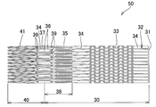
- FIG. 4 shows, as an example of the holding body and the valve opening portion of the artificial mitral valve device according to the first embodiment, when both are integrally formed as one stent, a part of the outer circumference thereof is along the major axis direction.
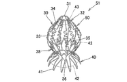
- FIG. 5A is a perspective view schematically showing a shape when the stent shown in FIG. 4 is expanded and deformed.
- FIG. 5B is a perspective view schematically showing a state in which an artificial valve is provided on the deformed form of the stent shown in FIG. 5A.
- the stent 50 constituting the holding body 30 and the valve opening portion 40 is configured such that a portion constituting the valve opening portion 40 extends continuously from one end of the portion constituting the holding body 30. ..
- the stent 50 has a cylindrical shape that opens at both ends in the long axis direction. Then, when the diameter of the stent 50 is expanded, the holding body 30 and the valve opening portion 40 are respectively configured to be deformable into predetermined shapes (see, for example, FIGS. 5A and 5B) described later.
- a plurality of linear bodies 32 extending in the long axis direction thereof are installed at predetermined intervals in the circumferential direction.
- the plurality of linear bodies 32 are connected by a connecting ring 31 at an end portion on the side opposite to the side adjacent to the valve opening portion 40.
- the connecting ring 31 has a structure in which the ends of adjacent linear bodies 32 are connected by linear struts extending in the circumferential direction. That is, it is a structure that cannot be expanded in diameter.
- the linear body 32 has a straight portion 34 extending linearly and a corrugated portion 33 having a corrugated structure that oscillates in a direction intersecting the long axis direction.
- a transition portion 36 extending toward the valve opening portion 40 is provided in a portion of the straight portion 34 that is closer to the valve opening portion 40 than the position where the connecting portion (also referred to as “first connecting portion”) 35 described later is connected. It is formed. In the transition portion 36, the holding body 30 and the valve opening portion 40 are continuous.
- the corrugated structure of the corrugated portion 33 has a structure in which peaks and valleys are alternately continuous, and has a sinusoidal structure.
- the waveform structure is not limited to this, for example, a structure in which peaks and valleys are formed by continuous V-shapes, and peaks and valleys are formed by alternating arcs with respect to the reference axis. Examples include the structure to be formed.
- the amplitude and wavelength of the waveform may be changed along the long axis direction or may be the same.
- the center position of the amplitude of the waveform structure may coincide with, for example, the center line in the long axis direction of the straight line portion 34, or the waveform structure is formed on either side of the center line of the straight line portion 34. It may be configured to be. In the latter case, the center position of the amplitude of the corrugated structure may be configured to coincide with the center line in the long axis direction of the straight line portion 34 of the adjacent linear body 32.
- the magnitude of the amplitude and the wavelength is not particularly limited, and can be appropriately determined in consideration of the ease of engagement with the protrusion of the pulmonary vein stent.
- the arrangement of the straight portion 34 and the corrugated portion 33 is not particularly limited, but the straight portion 33 is located at a position corresponding to the inlets 11a and 11b of the pulmonary veins 10a and 10b where the pulmonary vein stent is installed. It is preferable that the 34 and the corrugated portion 33 are provided.
- a straight line portion 34 is provided in a portion close to the connecting ring 31 and the valve opening portion 40, and a corrugated portion 33 is provided between them.
- the straight line portion 34 close to the connecting ring 31 is shorter than the side close to the valve opening portion 40. In this case, when inserted into the left atrium 3, the corrugated portion 33 tends to be easily positioned at the inlets 11a and 11b.
- the annulus portion 38 When placed in the left atrium 3 in a portion of the portion constituting the holding body 30 of the stent 50, which is adjacent to the portion constituting the valve opening portion 40, the annulus 13 of the left atrium 3 (see FIG. 1) An annulus portion 38 that will be in close proximity is provided.
- the annulus portion 38 has a plurality of straight portions 34 and a connecting portion 35 that connects the adjacent straight portions 34 so as to be expandable in diameter.
- the straight portion 34 includes a transition portion 36, which is continuous with the valve opening portion 40.
- the connecting portion 35 is provided adjacent to the stent 50 so as to have a corrugated structure in which peaks and valleys are alternately continuous along the circumferential direction of the stent 50 when the diameter is expanded. In the example shown in FIG.
- the connecting portion 35 has a structure in which a straight strut is bent in two, and exhibits a V-shaped shape when the diameter is expanded.
- the V-shaped bent portion is provided so as to face the connecting ring 31 side.
- a hollow dome-shaped retainer 30 having a large opening diameter can be formed (see, for example, FIGS. 5A, 5B).
- This opening diameter can be as large as the size of the annulus 13 of the left atrium 3.
- the connecting portion 35 is continuous in the circumferential direction so as to have a corrugated structure, and the straight portion 34 is present inside the top of the valley (or peak) of the corrugated structure, so that the straight portion 34 and the corrugated structure are connected.
- the structure is such that the portions 35 are alternately continuous in the circumferential direction. Therefore, when the stent 50 is expanded in diameter and deformed, the annulus portion 38 composed of these can be stably installed in the annulus 13 of the left atrium 3 or a portion in the vicinity thereof.
- every other of the plurality of linear bodies 32 is on the valve opening portion 40 side with respect to the position where the connecting portion 35 of the straight line portions 34 constituting the linear body 32 is connected.
- the number of artificial valve support portions 37 can be appropriately determined according to the number of linear bodies 32 and the like. Further, in the example shown in FIG.
- through holes 39 are provided at both ends of the artificial valve support portion 37, and the straight portion 34 to which the artificial valve support portion 37 is connected is provided at a position corresponding to these through holes 39. Also provided with a through hole 39. Further, in this example, the plurality of linear bodies 32 are provided independently without being connected to each other in the portion extending from the connecting ring 31 to the connecting portion 35, but the diameter can be expanded. Further connecting portions may be provided to be connected to each other.
- the portion constituting the valve opening portion 40 has a straight portion 34 and a skirt portion 41 having a corrugated structure in which peaks and valleys are alternately continuous in the circumferential direction of the stent 50.
- the skirt portion 41 continuously extends from the other end portion forming the dome shape of the holding body 30 via the transition portion 36, and gradually extends from the size of the other end portion. It is configured to have a widely expanding structure (see, for example, FIGS. 5A and 5B).
- the corrugated structure of the skirt portion 41 is a structure in which a V-shaped structure is continuous in the circumferential direction.
- the skirt portion 41 is connected to the end portion of the linear body 32 on the outside of the top portion of each peak portion (or valley portion) of the corrugated structure.
- the amplitude and wavelength of the waveform structure are constant in the example shown in FIG. 4, but are not limited to this. In addition, their sizes can be determined as appropriate.
- the stent 50 shown in FIG. 4 has a cylindrical shape having a constant outer diameter in the major axis direction. The size of the outer diameter shall be such that it can be inserted into the catheter when a delivery catheter is used as described later.
- the stent 50 By expanding the diameter of the stent 50 shown in FIG. 4 and shaping it according to a conventional method, for example, as shown in FIGS. 5A and 5B, the stent 50 has a top at one end, the diameter is gradually expanded from the top, and then the diameter is gradually reduced.
- a dome-shaped holding body 30 having the other end, and extending from the other end of the holding body 30 toward the side opposite to the top of the dome shape, gradually expanding from the size of the other end of the dome shape.
- the valve opening portion 40 is formed. That is, at the time of diameter expansion, a deformed body (50) of the stent 50 is formed in which the holding body 30 and the valve opening portion 40 are integrated so as to have a constricted structure at the continuous portion thereof.
- the other end of the holding portion 30 is formed at the center of the transition portion 36 of the linear body 32 in the length direction, and the most constricted portion is formed. Further, by forming the stent 50 using the shape memory alloy and shaping it according to a conventional method, it is possible to spontaneously deform the stent 50 when it is inserted into the left atrium to form, for example, the structure shown in FIGS. 5A and 5B.
- the covering portion 42 is formed in a predetermined range including the constricted portion of the deformed body (50) of the stent 50, and the tip of the connecting ring 31 which is the top of the dome shape is closed so as to close the opening portion of the connecting ring 31.
- the covering portion 42 and the tip cap portion 43 are shown by virtual lines in order to clarify the structure of the deformed body (50) of the stent 50.
- the dome shape of the assembly 51 shown in FIGS. 5A and 5B has an elliptical spherical shape, but is not limited to this.
- the dome shape is shaped so as to have a spherical shape as shown in FIGS. 6A and 6B. You may.
- the tip cap portion 43 may or may not be provided, but by providing it, it tends to be easy to prevent damage to the inner wall of the left atrium due to compression of the connecting ring 31 or the like.
- the range in which the covering portion 42 is provided needs to be provided in a range that does not hinder the inflow of blood from the pulmonary veins and can prevent the inflow of blood from the left ventricle.
- Such a range includes, for example, a predetermined range from the annulus 38 to a position corresponding to the inlets 11a and b of the pulmonary veins 10a and b of the holder 30, and the terminal of the annulus 38 to the valve opening 40.
- a predetermined range up to is mentioned. Further, in this range, the entire area from the predetermined position of the holding body 30 to the predetermined position of the valve opening portion 40 is covered by the covering portion 42.
- the covering portion 42 for example, conventionally known ones described in Patent Documents 1, 2 and the like can be used.
- a cloth formed of fibers selected from natural fibers, synthetic resin fibers and inorganic fibers, a sheet formed of synthetic resin (also referred to as a synthetic resin sheet), a biological membrane and the like can be mentioned.
- synthetic resins that can form cloths and sheets include polyesters, fluororesins, silicone resins, and the like.
- the biological membrane include pericardial tissues such as cows, pigs, and horses, and submucosa of the small intestine.
- the tip cap portion 43 one having the same configuration as that of the covering portion 42 can be used.
- the covering portion 42 and the tip cap portion 43 can be sewn to the stent 50 or a deformed body (50) having an expanded diameter thereof, for example, with sutures or the like.
- the coating by the covering portion 42 is preferably provided so as to cover the outside of the holding body 30 and the valve opening portion 40.
- the coating by the tip cap portion 43 is preferably provided so as to cover the connecting ring 31 and the entire opening thereof from the outside of the connecting ring 31.
- the valve device 52 constituting the combination valve device according to the first embodiment is provided with an artificial valve 44 in the vicinity of the annulus portion 38 of the holding body 30 of the assembly 51 shown in FIG. 5A. It is a thing.
- the artificial valve 44 is supported by the artificial valve support portion 37 and / or the straight portion 34 (transition portion 36). In FIGS. 5A and 5B, the artificial valve support portion 37 is omitted.
- the artificial valve 44 for example, conventionally known ones described in Patent Documents 1, 2 and the like, or commercially available ones can be used.
- Examples of such an artificial valve 44 include a biological valve and a mechanical valve.
- the biological valve include those formed by using one or more tissue leaflets such as bovine, porcine, and horse leaflets.
- the biological valve preferably has a structure in which these tissue flaps are supported by an artificial object such as a stent.
- an artificially supported structure when the valve device is inserted percutaneously into the left atrium, a structure supported by an expandable and contractible stent is preferable.
- the artificial valve 44 has a structure in which a plurality of (three in FIG. 5B) valve leaflets 46 are supported by a valve leaflet support portion 45 having a structure that can be expanded and contracted.
- the valve leaflet support portion 45 may be, for example, a stent having a mesh-like tubular structure that can be expanded and contracted, and may be coated in the same manner as the covering portion 43.
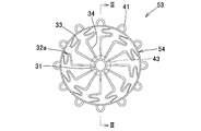
- FIG. 6A and 6B schematically show other examples of the valve device constituting the combination valve device according to the first embodiment.
- FIG. 6A is a diagram schematically showing the main part in the front view of the valve device
- FIG. 6B is a diagram schematically showing the main part in the II-II cross section of FIG. 6A.
- the valve device 53 shown in FIGS. 6A and 6B has a linear body (reference numeral 32a in FIG. 6A) in which the position of the corrugated portion 33 in the linear body 32 of the stent 50 shown in FIG. 4 is moved toward the valve opening portion 40. It is formed by using a stent 54 having the same structure as the stent 50, except that the holding portion (reference numeral 30a in FIG.
- FIGS. 6A and 6B are configured so as to be.
- the formation position of the corrugated portion 33 is adjusted according to the positions of the inlets 11a and b of the pulmonary veins 10a and b.
- the deformed body (54) of the stent 54 constituting the valve device 53 is shown in FIGS. 6A and 6B by expanding the diameter of the cylindrical stent 54 and shaping it according to a conventional method, as in the case of the cylindrical stent 50.
- a deformed body (54) of the shape can be formed.
- the dome shape of the holding body 30 is a spherical shape.
- valve apex 46a As the artificial valve 44a supported by the artificial valve support portion 37, only the valve apex 46a is shown by a virtual line, but the same one as in the case of the above-mentioned examples shown in FIGS. 5A and 5B can be used. The same components are designated by the same reference numerals and the description thereof will be omitted.
- the artificial mitral valve device according to the first embodiment can be configured by, for example, a combination of the above-mentioned pulmonary vein stent 20 and valve devices 52 and 53.
- a valve device 52 is installed in the left atrium 3 of the heart 9, and the entrances 11a and b are within one of the left and right pulmonary veins 10a and b of the two left pulmonary veins 10a and the two right pulmonary veins 10b, respectively.
- the protrusion 22 of the pulmonary vein stent 20 protrudes into the left atrium 3 from the inlets 11a and b, and is a holding body of the valve device 52 arranged in contact with the entire inner wall in the left atrium 3. It is engaged with the engaging portion of the linear body 32 constituting the 30. It can be said that an engaging portion is formed at a portion of the linear body 32 that engages with the protruding portion 22. This engaging portion can be a wavy line portion 33.
- one pulmonary vein stent 20 is provided in each of the left and right pulmonary veins, but one may be provided in only one of them, or one in one and two in the other. It may be provided in all or all.
- the artificial mitral valve device 55 can be installed in the heart and pulmonary veins by a conventionally known method. It is preferably placed percutaneously, but it can also be placed by open heart surgery such as median sternotomy. In the following, a percutaneous installation method of the artificial mitral valve device 55 will be described with reference to FIGS. 8 to 10 by taking the case of percutaneous installation as an example. Although FIGS. 8 to 10 describe a method of percutaneously installing the heart from the apex 14 of the heart, it can be installed from other routes or in combination of a plurality of routes.
- the delivery catheter 56 is percutaneously inserted from the apex 14 of the heart 9. Then, the pulmonary vein stent 20 in a reduced diameter state is guided from the left inlet 11a of the left pulmonary vein 10a into the left pulmonary vein 10a via the delivery curator 56 using a guide wire and an induction catheter. When it is delivered from the induction catheter into the left pulmonary vein 10a, it is in a preformed diameter-expanded state and is fixed in contact with the inner wall of the left pulmonary vein 10a. It may be configured to expand the diameter by using a balloon catheter.
- the protruding portion 22 of the pulmonary vein stent 20 installed in the left pulmonary vein 10a is in a state of protruding from the left entrance 11a into the left atrium 3.
- FIG. 8 shows the state at this time.
- another pulmonary vein stent 20 is placed in the right pulmonary vein 10b, and the pulmonary vein stent 20 is fixed in a state where the protruding portion 22 protrudes into the left atrium 3 from the right entrance 11b.
- the valve device 52 which has been shaped in advance and then reduced in diameter, is gradually inserted into the left atrium 3 via a delivery catheter 56 using an induction catheter or the like to bring the shaped diameter into an expanded state.
- Gradually expand (Fig. 9).
- the entire retainer 30 When the entire retainer 30 is projected from the delivery catheter 56, it engages with some of the protrusions 22 of the pulmonary vein stent 20 to rotate the valve device 52 around the central axis and tilt the central axis. It is possible to suppress or suppress the movement of the pulmonary vein stent 20 toward the left atrium 3.
- FIG. 10 shows the state at this time.
- the combination valve device 55 is installed in the heart 9, and the valve device 52 is more stable than before even if the heart expands and contracts. Is installed in the heart 9.
- the artificial mitral valve device includes a holder having a predetermined structure described later, a covering portion, an artificial valve having a predetermined structure described later, and a stent for pulmonary veins. It has a structure not provided with a valve opening portion in the first embodiment.
- the valve opening in the first embodiment tends to function effectively to secure the valve device in the left atrium, but for example, the hypertrophic cardiomyopathy narrows the outflow path of blood from the left ventricle to the aorta. In such cases, the valve opening may impede the movement of the aortic valve and block its outflow tract.
- an artificial mitral valve device that can be stably fixed can be applied even in such a case.
- a valve device in which the holding body and the artificial valve are integrated is used, but in the second embodiment, the holding body and the artificial valve are configured separately.
- the valve device of the first embodiment since the holding body and the artificial valve are integrated, it is considered that the valve device is bulky and it may be difficult to insert it into the heart from outside the body using a catheter. Be done. In particular, it seems that it tends to be difficult to adopt the transfemoral approach, which is considered to be the least invasive.
- the retainer and the artificial valve are configured separately, and both are engaged in the left atrium to be engaged in the left atrium. Therefore, the first embodiment is adopted. It is possible to suppress bulkiness more than the valve device in the form.
- the artificial mitral valve device according to the second embodiment is provided with a pulmonary vein stent as in the first embodiment, and the same device can be applied. Therefore, in the second embodiment, the description of the pulmonary vein stent in the first embodiment will be referred to.
- the holding body constituting the artificial mitral valve device according to the second embodiment has a predetermined engaging portion and an annulus portion, is deformed into a dome shape, and is surrounded by the annulus portion to form an annular shape. An open end to be opened and an artificial valve support portion that can extend inward of the open end are formed.
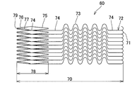
- FIG. 11 shows, as an example of an embodiment of the holding body constituting the artificial mitral valve device according to the present invention, when the holding body 70 is composed of a cylindrical stent 60 that can be deformed into a dome shape, the stent 60 is used. It shows the development view before expanding the diameter.
- FIG. 11 shows, as an example of an embodiment of the holding body constituting the artificial mitral valve device according to the present invention, when the holding body 70 is composed of a cylindrical stent 60 that can be deformed into a dome shape, the stent 60 is used. It shows the development view before expanding the diameter.
- FIG. 11 shows, as an example of an embodiment of the holding body constituting the artificial mitral valve device according
- FIG. 12 is a perspective view schematically showing a holder 70 formed by expanding the diameter of the stent 60 shown in FIG. 11 and deforming it into a dome shape.
- FIG. 12 shows a part of the holding body 70 for convenience, and shows the configuration on the front side with respect to the paper surface, and omits the configuration on the back side.
- FIG. 13 is a front view of the support 70 shown in FIG. In FIGS. 11 to 13 and 15, the struts constituting the stent 60 and the support 70 formed by the stent 60 are shown graphically. Further, in FIG. 13, for convenience, the configuration on the front side with respect to the paper surface is shown by a thick line, and the configuration on the back side is shown by a thin line.
- the stent 60 constituting the holding body 70 has a cylindrical shape having a constant outer diameter and is open at both ends in the major axis direction. Then, when the diameter of the stent 60 is expanded, the holding body 70 is configured to be deformable into a dome shape (see, for example, FIG. 12 and the like) described later. Further, the stent 60 has an annulus portion 78 in a predetermined range thereof, which comes close to the innate annulus 13 when the stent 60 is expanded in diameter and placed in the left atrium 3.
- a plurality of linear bodies 72 extending in the long axis direction of the stent 60 are installed at predetermined intervals in the circumferential direction.
- the number of striatum 72 is not particularly limited as long as it can engage with the protrusion 22 of the pulmonary vein stent 20.
- the number of valves is larger than the outer diameter of the delivery catheter.
- the plurality of linear bodies 72 have one end and the other end, with a connecting ring 71 at one end and a connecting portion (also referred to as a "second connecting portion") at the other end. ) 76 are connected.
- the connecting ring 71 has a structure in which one end of an adjacent linear body 72 is connected by an arch-shaped strut that extends in the circumferential direction and curves convexly in the long axis direction.
- the connecting ring 71 is configured so that the diameter cannot be substantially increased. When inserted into the left atrium 3, the connecting ring 71 becomes a portion arranged in direct or indirect contact with the inner wall in the vicinity of the apex 12 of the left atrium 3.
- the connecting portion (second connecting portion) 76 has a corrugated structure in which peaks and valleys are alternately continuous in the circumferential direction of the stent 60, and the stent 60 has a structure in which the diameter can be expanded from the reduced diameter state. ..
- the adjacent linear bodies 72 are connected to the connecting portion 76 at the adjacent mountain portion of the connecting portion 76.
- the end 79 of the valley of the connecting portion 76 forms the open end 80 of the retainer 70 when the stent 60 is expanded in diameter (see, for example, FIGS. 13 and 16).
- the linear body 72 has a linear portion 74 extending linearly and a corrugated portion 73 having a corrugated structure that oscillates in a direction intersecting the long axis direction.
- the structure of the corrugated portion 73 has a structure in which peaks and valleys are alternately continuous, and has a sinusoidal structure.
- the waveform structure is not limited to this, for example, a structure in which peaks and valleys are formed by continuous V-shapes, and peaks and valleys are formed by alternating arcs with respect to the reference axis. Examples include the structure to be formed.
- the amplitude and wavelength of the waveform may be changed along the long axis direction or may be the same.
- the center position of the amplitude of the waveform structure may coincide with, for example, the center line in the long axis direction of the straight line portion 74, or the waveform structure is formed on either side of the center line of the straight line portion 74. It may be configured to be. In the latter case, the center position of the amplitude of the corrugated structure may be configured to coincide with the center line in the long axis direction of the straight line portion 74 of the adjacent linear body 72.
- the magnitude of the amplitude and the wavelength is not particularly limited, and can be appropriately determined in consideration of the ease of engagement with the protrusion of the pulmonary vein stent.
- the arrangement of the straight portion 74 and the corrugated portion 73 is not particularly limited, but the straight portion 73 is located at a position corresponding to the inlets 11a and 11b of the pulmonary veins 10a and 10b where the pulmonary vein stent is installed. It is preferable that the 74 and the corrugated portion 73 are provided.
- a straight line portion 74 is provided in a portion close to the connecting ring 71 and the connecting portion (second connecting portion) 76, and a corrugated portion 73 is provided between them.
- the straight line portion 74 close to the connecting ring 71 is shorter than the side close to the connecting portion (second connecting portion) 76. In this case, when inserted into the left atrium 3, the corrugated portion 73 tends to be easily positioned at the inlets 11a and 11b.
- the annulus portion 78 has a plurality of straight portions 74 provided in a portion close to the other end side of the linear body 72, and the adjacent straight portions 74 thereof are expanded in diameter at a portion other than the end thereof. It is composed of a connecting portion (also referred to as a first connecting portion) 75 that is possibly connected and a connecting portion (second connecting portion) 76 that connects the other end of the linear body 72.
- the first connecting portion 75 is provided adjacent to each other in the circumferential direction so as to have a corrugated structure in which peaks and valleys are alternately continuous along the circumferential direction of the stent 60 when the diameter is expanded.
- the first connecting portion 75 has a structure in which a linear strut is bent in two, and exhibits a V-shaped shape when the diameter is expanded.
- the V-shaped bent portion is provided so as to face the connecting ring 71.
- the diameter of the connecting ring 71 is not increased, but is increased at the first connecting portion 75 and the second connecting portion 76. Then, the connecting ring 71, which is one end, is used as the top, and the diameter is gradually increased from the top and then gradually reduced. At the end 79 of the second connecting portion 76, the opening diameter is larger than the opening diameter of the connecting ring 71 at the top.
- a hollow dome-shaped retainer 70 with an open end 80 of diameter can be formed (see, eg, FIGS. 12, 13, 16). The opening diameter of the opening end 80 can be about the same as the outer diameter of the artificial valve 84, which will be described later.
- the first connecting portion 75 is continuous in the circumferential direction so as to have a corrugated structure, and the straight portion 74 exists inside the top of the valley (or peak) of the corrugated structure, so that the straight portion 74 and the corrugated structure are present.
- the first connecting portion 75 of the above is alternately continuous in the circumferential direction. Therefore, when the stent 60 is expanded in diameter and deformed, the annulus portion 78 composed of these can be stably installed in the annulus 13 of the left atrium 3 or a portion in the vicinity thereof.
- the position where the first connecting portion 75 of the straight line portion 74 is connected is located on the side of the second connecting portion 76.
- An artificial valve support portion 77 that branches from the straight portion 74 and extends linearly toward the second connecting portion 76 side is formed.
- the artificial valve support portion 77 is formed so as to extend inward of the opening end 80 when the stent 60 is deformed into a dome shape.
- the straight line portion 74 is deformed so as to have a predetermined angle with respect to the axial direction, and is deformed so as to bend inward of the dome shape.
- the number of artificial valve support portions 77 can be appropriately determined according to the number of linear bodies 72 and the like. Further, as in the example shown in FIG. 4, the artificial valve support portion 77 may be provided in every other of the plurality of linear bodies 72. Further, it may have the same structure as the example shown in FIG. For example, through holes (see reference numeral 39 in FIG. 4) may be provided at both ends of the artificial valve support portion 77, or a straight portion to which the artificial valve support portion 77 is connected at a position corresponding to these holes. The 74 may also be provided with a through hole. Further, in this example, the plurality of linear bodies 72 are provided independently without being connected to each other in the portion extending from the connecting ring 71 to the first connecting portion 75, but the diameter can be expanded. Further, a connecting portion for connecting to each other may be further provided.
- the second connecting portion 76 has a corrugated structure in which peaks and valleys are alternately continuous in the circumferential direction of the stent 60.
- the amplitude and wavelength of the waveform structure are constant in the examples shown in FIGS. 11 and 12, but are not limited to this. Further, their size can be determined so as to be the size of the opening end 80 that can be engaged with the artificial valve 84.
- the open end 80 of the holding body 70 is composed of the end portion 79 of the second connecting portion 76, and the end portion 79 can be configured to be engaged with the artificial valve.
- a predetermined range from the end portion 79 of the second connecting portion 76 is formed inside the dome shape of the holding body 70 so as to be bent toward the connecting ring 71 side, and the bent portion is formed. It is also possible to use an engaging portion that can be engaged with the artificial valve 84.
- the opening end in this case is composed of a bent bending point, and the engaging portion with the artificial valve 84 is formed inside the holding body 70 in the vicinity of the opening end.
- the same material as that described in the pulmonary vein stent 20 can be used. Further, the width and thickness of the strut can be appropriately determined according to the required characteristics of each part.
- the stent 60 shown in FIG. 11 has a cylindrical shape having a constant outer diameter in the major axis direction. The size of the outer diameter shall be such that it can be inserted into the catheter when a delivery catheter is used as described later.
- FIGS. 11 By expanding the diameter of the stent 60 shown in FIG. 11 and shaping it according to a conventional method, for example, as shown in FIGS. A dome-shaped retainer 70 having the other end is formed. Further, the linear artificial valve support portion 77 is formed so as to bend and extend toward the inside of the opening end 80 or the inside of the dome shape. Further, by forming the stent 60 using a shape memory alloy and shaping it according to a conventional method, it is possible to spontaneously deform the stent 60 when it is inserted into the left atrium to form the structure shown in FIGS. 12, 13, and the like. .. The dome shape of the holding body 70 shown in FIGS.
- a covering portion is provided in a predetermined range.
- a covering portion 82 (indicated by a virtual line) is provided at a portion corresponding to the annulus portion 78 in the stent 60 of FIG. Further, the covering portion 82 is provided on the outside and the inside of the annulus portion 78 of the holding body 70 from the viewpoint of liquidtightness with the artificial valve 84.
- the method of arranging the inside and the outside is not particularly limited.
- the inside and the outside are configured to be a continuous body over the entire circumference of the holding body 70.
- the connecting ring 71 of the holding body 70 is provided with a tip cap portion 83 so as to close the opening portion of the connecting ring 71, as shown in FIGS. May be good.
- the same material as in the case of the first embodiment can be adopted. Further, the covering portion 82 and the tip cap portion 83 can be sewn to the stent 60 or the holding body 70 having an expanded diameter thereof with sutures or the like, as in the case of the first embodiment.
- the artificial valve applicable to the artificial mitral valve device according to the second embodiment is expanded from a reduced diameter state that can be inserted into the inside of the holding body at the opening end of the holding body according to the second embodiment to an enlarged diameter state.
- a cylindrical valve stent body having an engaging portion that can engage with at least one selected from the artificial valve support portion of the retainer, the open end and the vicinity of the open end, and the valve stent body. It has a valve body that is fixed in advance inside the.
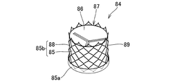
- FIG. 14 is a perspective view schematically showing an artificial valve 84 applicable to the second embodiment. In FIG. 14, for convenience, the configuration of the valve stent body is shown graphically.
- FIG. 14 is a diagram showing a diameter-expanded state.
- the artificial valve 84 has a valve stent main body 88 and a valve body 87.
- the valve stent body 88 has a diameter-expandable cylindrical shape, and the wall portion of the cylinder has a diameter-expandable mesh-like structure.
- rhombic-shaped units composed of linear struts are continuously provided in the circumferential direction and the long axis direction, and have a mesh-like cylindrical structure as a whole.
- the mesh-like structure engages with one or more of the prosthetic valve support 77 and / or the open end 80 (end 79) formed in the retainer 70 when the diameter is increased. It is possible.
- the engaging portion 89 is provided in a predetermined range from one end in the longitudinal direction of the valve stent body 88 or the portion corresponding to the opening end 80 of the holding body 70. It can be easily formed.
- the structure of the wall portion constituting the valve stent main body 88 is not limited to such a diameter-expandable mesh shape, for example, the structure shown in FIG. 2 and other general diameter-expandable stent structures. Can be adopted.
- the material of the valve stent body 88 the same material as that of the pulmonary vein stent 20 can be used.
- the valve body 87 is fixed in advance inside the valve stent body 88.
- the valve body 87 shown in FIG. 14 has a structure in which a plurality of (three in the example shown in FIG. 14) valve tips 86 are supported by a tubular portion 85 that can be expanded and contracted.
- the valve body 87 is preferably derived from a living body, formed by using a resin having good biocompatibility, or a combination thereof.
- the valve body derived from a living body include those formed by using one or more tissue leaflets such as bovine, porcine, and horse leaflets and their peripheral tissues.
- the resin having good biocompatibility include silicone resin and the like.
- valve stent body 88 and the valve body 87 There is no particular limitation on how to fix the valve stent body 88 and the valve body 87.
- one end 85a (a portion of the holder 70 close to the open end 80) of the tubular portion 85 installed inside the valve stent body 88 is replaced with the valve stent body 88. Both are fixed by bending to the outside of.
- the valve leaflet support portion 85b can be formed by the tubular portion 85 of the valve body 87 and the valve stent body 88.
- the artificial valve applicable to the second embodiment is not limited to the one shown in FIG. 14, and a commercially available valve for the heart can be adopted.
- the artificial mitral valve device can be configured by combining a pulmonary vein stent 20, a retainer 70 having a covering portion 82 provided in a predetermined range, and an artificial valve 84.
- the artificial mitral valve device can be installed in the heart and pulmonary veins by a conventionally known method.
- the pulmonary vein stent 20 is inserted into the pulmonary veins 11a and 11a (see, for example, FIG. 8 for reference), and then the diameter is reduced via the delivery catheter.
- Stent 60 is inserted into the left atrium 3 (see, for example, FIGS. 9 and 10 for reference).
- the stent 60 is expanded in diameter in the left atrium 3 to form a dome-shaped retainer 70.
- the protruding portion 22 of the pulmonary vein stent 20 and the engaging portion of the linear body 72 constituting the holder 70 are engaged.
- an engaging portion is formed at a portion of the linear body 72 that engages with the protruding portion 22.
- This engaging portion can be a wavy line portion 73.
- FIG. 15 is a perspective view schematically showing a state in which the holding body 70 shown in FIG. 12 and the artificial valve 84 shown in FIG. 14 are engaged with each other.
- FIG. 16 is an explanatory view schematically showing a main part in the cross section III-III shown in FIG.
- the holding body 70 is provided with an artificial valve 84 having a valve tip 86 (shown by a virtual line in FIG. 16) inside the dome shape, and the tip cap 83 serves as a top.
- a covering portion 82 is provided on the annulus portion 78 on the connecting ring 71 (both are shown by virtual lines). Then, in the example shown in FIG. 16, the artificial valve support portion 77 of the holding body 70 and the open end 80 (the end 79 of the second connecting portion 76) are engaged with the artificial valve 84 via the covering portion 82. .. Since the inside and outside of the support 70 are formed as a continuous body in the covering portion 82, the artificial valve support 70 bends inward as shown in FIG.
- the inner covering portion 82 is lifted by the end portion of the artificial valve support portion 70, and the outer peripheral surface of the artificial valve 84, particularly the valve stent body 88, is engaged between the open end 80 and the artificial valve support portion 70.
- a peripheral surface is formed so as to face the joint portion 89.
- the artificial valve 84 is installed at a predetermined position of the holding body 70, and by engaging the artificial valve 84 with the holding body 70, the left atrium 3 and at least one pulmonary vein 11a, b are formed.
- An artificial mitral valve device according to a second embodiment having a pulmonary vein stent 20, a holder 70 provided with a covering portion 82, and an artificial valve 84 is formed.
- the holder 70, the pulmonary vein stent 20 and the artificial valve 84 are engaged and integrated, and the movement of the holder 70 in the left atrium 3 is performed. Is suppressed, and the artificial valve 84 can be stably installed in the heart.
- the artificial mitral valve device can be applied to a case of hypertrophic myocardium.
- the holding body 70 and the artificial valve 84 have a structure that can be engaged in the heart, a transfemoral approach can be adopted, less invasive treatment is possible, and only the artificial valve can be easily replaced. be able to.
Abstract
La présente invention peut fournir un dispositif de valve mitrale artificielle capable d'agencer une valve artificielle qui remplace une valve mitrale naturelle de manière plus stable qu'auparavant, le dispositif de valve mitrale artificielle comprenant : une endoprothèse de veine pulmonaire comprenant un corps d'endoprothèse qui est installé à l'intérieur d'une veine pulmonaire à proximité d'une entrée dans une oreillette gauche de la veine pulmonaire, et une saillie qui peut faire saillie à partir de l'entrée dans l'oreillette gauche et s'étendre vers l'extérieur à partir du corps d'endoprothèse ; un support comprenant une partie annulaire qui est formée à une position proche d'un anneau de l'oreillette gauche, et une partie de mise en prise qui est installée à l'intérieur de l'oreillette gauche, peut être déformée en forme de dôme creux, et peut être mise en prise avec la partie saillante de l'endoprothèse de veine pulmonaire en entrant en contact avec une paroi interne de l'oreillette gauche à proximité de l'entrée de la veine pulmonaire en étant déformée en forme de dôme ; une partie de recouvrement qui recouvre de manière étanche aux liquides une plage prédéterminée du corps de maintien ; et une valve artificielle qui est disposée à proximité de la partie annulaire.
Priority Applications (1)
| Application Number | Priority Date | Filing Date | Title |
|---|---|---|---|
| JP2022510698A JPWO2021193873A1 (fr) | 2020-03-26 | 2021-03-25 |
Applications Claiming Priority (2)
| Application Number | Priority Date | Filing Date | Title |
|---|---|---|---|
| JP2020056135 | 2020-03-26 | ||
| JP2020-056135 | 2020-03-26 |
Publications (1)
| Publication Number | Publication Date |
|---|---|
| WO2021193873A1 true WO2021193873A1 (fr) | 2021-09-30 |
Family
ID=77892719
Family Applications (1)
| Application Number | Title | Priority Date | Filing Date |
|---|---|---|---|
| PCT/JP2021/012728 WO2021193873A1 (fr) | 2020-03-26 | 2021-03-25 | Dispositif de valve mitrale artificielle |
Country Status (2)
| Country | Link |
|---|---|
| JP (1) | JPWO2021193873A1 (fr) |
| WO (1) | WO2021193873A1 (fr) |
Cited By (1)
| Publication number | Priority date | Publication date | Assignee | Title |
|---|---|---|---|---|
| WO2023155538A1 (fr) * | 2022-02-18 | 2023-08-24 | 上海臻亿医疗科技有限公司 | Dispositifs d'ancrage de valve cardiaque artificielle et système de valve cardiaque artificielle |
Citations (2)
| Publication number | Priority date | Publication date | Assignee | Title |
|---|---|---|---|---|
| US20100217382A1 (en) * | 2009-02-25 | 2010-08-26 | Edwards Lifesciences | Mitral valve replacement with atrial anchoring |
| JP2017148485A (ja) * | 2015-12-22 | 2017-08-31 | エヌヴィーティー アーゲー | 僧帽弁接合強化用補綴デバイス |
-
2021
- 2021-03-25 JP JP2022510698A patent/JPWO2021193873A1/ja active Pending
- 2021-03-25 WO PCT/JP2021/012728 patent/WO2021193873A1/fr active Application Filing
Patent Citations (2)
| Publication number | Priority date | Publication date | Assignee | Title |
|---|---|---|---|---|
| US20100217382A1 (en) * | 2009-02-25 | 2010-08-26 | Edwards Lifesciences | Mitral valve replacement with atrial anchoring |
| JP2017148485A (ja) * | 2015-12-22 | 2017-08-31 | エヌヴィーティー アーゲー | 僧帽弁接合強化用補綴デバイス |
Cited By (1)
| Publication number | Priority date | Publication date | Assignee | Title |
|---|---|---|---|---|
| WO2023155538A1 (fr) * | 2022-02-18 | 2023-08-24 | 上海臻亿医疗科技有限公司 | Dispositifs d'ancrage de valve cardiaque artificielle et système de valve cardiaque artificielle |
Also Published As
| Publication number | Publication date |
|---|---|
| JPWO2021193873A1 (fr) | 2021-09-30 |
Similar Documents
| Publication | Publication Date | Title |
|---|---|---|
| US11147665B2 (en) | Replacement cardiac valves and methods of use and manufacture | |
| US10842476B2 (en) | Heart valve prosthesis and method | |
| JP6594289B2 (ja) | 僧帽弁接合強化用補綴デバイス | |
| US20210282924A1 (en) | Prosthetic valve and deployment system | |
| CN108578016B (zh) | 一种经心尖植入式二尖瓣瓣膜装置 | |
| KR101617052B1 (ko) | 스텐트 부착 심장 판막 장치 | |
| US20180036122A1 (en) | Implantable Valve Prosthesis | |
| JP2019193874A (ja) | 僧帽弁逆流症処置用のデバイスおよび方法 | |
| JP2017504410A (ja) | 心弁用人工器官 | |
| US20100256752A1 (en) | Prosthetic heart valves, support structures and systems and methods for implanting the same, | |
| CN114502103A (zh) | 房室瓣置换 | |
| WO2021193873A1 (fr) | Dispositif de valve mitrale artificielle | |
| US20220175523A1 (en) | Stent device for a prosthetic heart valve | |
| US20230390052A1 (en) | Prosthetic valve systems, components, and methods | |
| CN116869708A (zh) | 一种瓣膜置换装置 | |
| CN115335005A (zh) | 人工心脏瓣膜装置、系统和方法 |
Legal Events
| Date | Code | Title | Description |
|---|---|---|---|
| 121 | Ep: the epo has been informed by wipo that ep was designated in this application |
Ref document number: 21774331 Country of ref document: EP Kind code of ref document: A1 |
|
| ENP | Entry into the national phase |
Ref document number: 2022510698 Country of ref document: JP Kind code of ref document: A |
|
| NENP | Non-entry into the national phase |
Ref country code: DE |
|
| 122 | Ep: pct application non-entry in european phase |
Ref document number: 21774331 Country of ref document: EP Kind code of ref document: A1 |