WO2021193386A1 - 通信装置、通信システム及び通信方法 - Google Patents
通信装置、通信システム及び通信方法 Download PDFInfo
- Publication number
- WO2021193386A1 WO2021193386A1 PCT/JP2021/011254 JP2021011254W WO2021193386A1 WO 2021193386 A1 WO2021193386 A1 WO 2021193386A1 JP 2021011254 W JP2021011254 W JP 2021011254W WO 2021193386 A1 WO2021193386 A1 WO 2021193386A1
- Authority
- WO
- WIPO (PCT)
- Prior art keywords
- information
- distance
- altitude
- acquisition unit
- acquires
- Prior art date
- Legal status (The legal status is an assumption and is not a legal conclusion. Google has not performed a legal analysis and makes no representation as to the accuracy of the status listed.)
- Ceased
Links
Images













Classifications
-
- G—PHYSICS
- G01—MEASURING; TESTING
- G01S—RADIO DIRECTION-FINDING; RADIO NAVIGATION; DETERMINING DISTANCE OR VELOCITY BY USE OF RADIO WAVES; LOCATING OR PRESENCE-DETECTING BY USE OF THE REFLECTION OR RERADIATION OF RADIO WAVES; ANALOGOUS ARRANGEMENTS USING OTHER WAVES
- G01S5/00—Position-fixing by co-ordinating two or more direction or position line determinations; Position-fixing by co-ordinating two or more distance determinations
- G01S5/02—Position-fixing by co-ordinating two or more direction or position line determinations; Position-fixing by co-ordinating two or more distance determinations using radio waves
- G01S5/14—Determining absolute distances from a plurality of spaced points of known location
-
- G—PHYSICS
- G01—MEASURING; TESTING
- G01S—RADIO DIRECTION-FINDING; RADIO NAVIGATION; DETERMINING DISTANCE OR VELOCITY BY USE OF RADIO WAVES; LOCATING OR PRESENCE-DETECTING BY USE OF THE REFLECTION OR RERADIATION OF RADIO WAVES; ANALOGOUS ARRANGEMENTS USING OTHER WAVES
- G01S5/00—Position-fixing by co-ordinating two or more direction or position line determinations; Position-fixing by co-ordinating two or more distance determinations
- G01S5/02—Position-fixing by co-ordinating two or more direction or position line determinations; Position-fixing by co-ordinating two or more distance determinations using radio waves
- G01S5/0205—Details
- G01S5/0218—Multipath in signal reception
-
- G—PHYSICS
- G01—MEASURING; TESTING
- G01C—MEASURING DISTANCES, LEVELS OR BEARINGS; SURVEYING; NAVIGATION; GYROSCOPIC INSTRUMENTS; PHOTOGRAMMETRY OR VIDEOGRAMMETRY
- G01C21/00—Navigation; Navigational instruments not provided for in groups G01C1/00 - G01C19/00
- G01C21/38—Electronic maps specially adapted for navigation; Updating thereof
- G01C21/3804—Creation or updating of map data
-
- G—PHYSICS
- G01—MEASURING; TESTING
- G01C—MEASURING DISTANCES, LEVELS OR BEARINGS; SURVEYING; NAVIGATION; GYROSCOPIC INSTRUMENTS; PHOTOGRAMMETRY OR VIDEOGRAMMETRY
- G01C5/00—Measuring height; Measuring distances transverse to line of sight; Levelling between separated points; Surveyors' levels
- G01C5/06—Measuring height; Measuring distances transverse to line of sight; Levelling between separated points; Surveyors' levels by using barometric means
-
- G—PHYSICS
- G01—MEASURING; TESTING
- G01S—RADIO DIRECTION-FINDING; RADIO NAVIGATION; DETERMINING DISTANCE OR VELOCITY BY USE OF RADIO WAVES; LOCATING OR PRESENCE-DETECTING BY USE OF THE REFLECTION OR RERADIATION OF RADIO WAVES; ANALOGOUS ARRANGEMENTS USING OTHER WAVES
- G01S13/00—Systems using the reflection or reradiation of radio waves, e.g. radar systems; Analogous systems using reflection or reradiation of waves whose nature or wavelength is irrelevant or unspecified
- G01S13/74—Systems using reradiation of radio waves, e.g. secondary radar systems; Analogous systems
- G01S13/76—Systems using reradiation of radio waves, e.g. secondary radar systems; Analogous systems wherein pulse-type signals are transmitted
- G01S13/765—Systems using reradiation of radio waves, e.g. secondary radar systems; Analogous systems wherein pulse-type signals are transmitted with exchange of information between interrogator and responder
-
- G—PHYSICS
- G01—MEASURING; TESTING
- G01S—RADIO DIRECTION-FINDING; RADIO NAVIGATION; DETERMINING DISTANCE OR VELOCITY BY USE OF RADIO WAVES; LOCATING OR PRESENCE-DETECTING BY USE OF THE REFLECTION OR RERADIATION OF RADIO WAVES; ANALOGOUS ARRANGEMENTS USING OTHER WAVES
- G01S5/00—Position-fixing by co-ordinating two or more direction or position line determinations; Position-fixing by co-ordinating two or more distance determinations
- G01S5/0009—Transmission of position information to remote stations
- G01S5/0018—Transmission from mobile station to base station
-
- G—PHYSICS
- G01—MEASURING; TESTING
- G01S—RADIO DIRECTION-FINDING; RADIO NAVIGATION; DETERMINING DISTANCE OR VELOCITY BY USE OF RADIO WAVES; LOCATING OR PRESENCE-DETECTING BY USE OF THE REFLECTION OR RERADIATION OF RADIO WAVES; ANALOGOUS ARRANGEMENTS USING OTHER WAVES
- G01S5/00—Position-fixing by co-ordinating two or more direction or position line determinations; Position-fixing by co-ordinating two or more distance determinations
- G01S5/02—Position-fixing by co-ordinating two or more direction or position line determinations; Position-fixing by co-ordinating two or more distance determinations using radio waves
- G01S5/0205—Details
- G01S5/0226—Transmitters
-
- G—PHYSICS
- G01—MEASURING; TESTING
- G01S—RADIO DIRECTION-FINDING; RADIO NAVIGATION; DETERMINING DISTANCE OR VELOCITY BY USE OF RADIO WAVES; LOCATING OR PRESENCE-DETECTING BY USE OF THE REFLECTION OR RERADIATION OF RADIO WAVES; ANALOGOUS ARRANGEMENTS USING OTHER WAVES
- G01S5/00—Position-fixing by co-ordinating two or more direction or position line determinations; Position-fixing by co-ordinating two or more distance determinations
- G01S5/02—Position-fixing by co-ordinating two or more direction or position line determinations; Position-fixing by co-ordinating two or more distance determinations using radio waves
- G01S5/0252—Radio frequency fingerprinting
- G01S5/02521—Radio frequency fingerprinting using a radio-map
- G01S5/02524—Creating or updating the radio-map
-
- G—PHYSICS
- G01—MEASURING; TESTING
- G01S—RADIO DIRECTION-FINDING; RADIO NAVIGATION; DETERMINING DISTANCE OR VELOCITY BY USE OF RADIO WAVES; LOCATING OR PRESENCE-DETECTING BY USE OF THE REFLECTION OR RERADIATION OF RADIO WAVES; ANALOGOUS ARRANGEMENTS USING OTHER WAVES
- G01S5/00—Position-fixing by co-ordinating two or more direction or position line determinations; Position-fixing by co-ordinating two or more distance determinations
- G01S5/02—Position-fixing by co-ordinating two or more direction or position line determinations; Position-fixing by co-ordinating two or more distance determinations using radio waves
- G01S5/0257—Hybrid positioning
- G01S5/0258—Hybrid positioning by combining or switching between measurements derived from different systems
- G01S5/02585—Hybrid positioning by combining or switching between measurements derived from different systems at least one of the measurements being a non-radio measurement
-
- G—PHYSICS
- G01—MEASURING; TESTING
- G01S—RADIO DIRECTION-FINDING; RADIO NAVIGATION; DETERMINING DISTANCE OR VELOCITY BY USE OF RADIO WAVES; LOCATING OR PRESENCE-DETECTING BY USE OF THE REFLECTION OR RERADIATION OF RADIO WAVES; ANALOGOUS ARRANGEMENTS USING OTHER WAVES
- G01S5/00—Position-fixing by co-ordinating two or more direction or position line determinations; Position-fixing by co-ordinating two or more distance determinations
- G01S5/18—Position-fixing by co-ordinating two or more direction or position line determinations; Position-fixing by co-ordinating two or more distance determinations using ultrasonic, sonic or infrasonic waves
- G01S5/26—Position of receiver fixed by co-ordinating a plurality of position lines defined by path-difference measurements
-
- H—ELECTRICITY
- H04—ELECTRIC COMMUNICATION TECHNIQUE
- H04W—WIRELESS COMMUNICATION NETWORKS
- H04W24/00—Supervisory, monitoring or testing arrangements
- H04W24/08—Testing, supervising or monitoring using real traffic
-
- H—ELECTRICITY
- H04—ELECTRIC COMMUNICATION TECHNIQUE
- H04W—WIRELESS COMMUNICATION NETWORKS
- H04W64/00—Locating users or terminals or network equipment for network management purposes, e.g. mobility management
-
- G—PHYSICS
- G01—MEASURING; TESTING
- G01C—MEASURING DISTANCES, LEVELS OR BEARINGS; SURVEYING; NAVIGATION; GYROSCOPIC INSTRUMENTS; PHOTOGRAMMETRY OR VIDEOGRAMMETRY
- G01C21/00—Navigation; Navigational instruments not provided for in groups G01C1/00 - G01C19/00
- G01C21/20—Instruments for performing navigational calculations
- G01C21/206—Instruments for performing navigational calculations specially adapted for indoor navigation
-
- G—PHYSICS
- G01—MEASURING; TESTING
- G01S—RADIO DIRECTION-FINDING; RADIO NAVIGATION; DETERMINING DISTANCE OR VELOCITY BY USE OF RADIO WAVES; LOCATING OR PRESENCE-DETECTING BY USE OF THE REFLECTION OR RERADIATION OF RADIO WAVES; ANALOGOUS ARRANGEMENTS USING OTHER WAVES
- G01S13/00—Systems using the reflection or reradiation of radio waves, e.g. radar systems; Analogous systems using reflection or reradiation of waves whose nature or wavelength is irrelevant or unspecified
- G01S13/86—Combinations of radar systems with non-radar systems, e.g. sonar, direction finder
-
- G—PHYSICS
- G01—MEASURING; TESTING
- G01S—RADIO DIRECTION-FINDING; RADIO NAVIGATION; DETERMINING DISTANCE OR VELOCITY BY USE OF RADIO WAVES; LOCATING OR PRESENCE-DETECTING BY USE OF THE REFLECTION OR RERADIATION OF RADIO WAVES; ANALOGOUS ARRANGEMENTS USING OTHER WAVES
- G01S2205/00—Position-fixing by co-ordinating two or more direction or position line determinations; Position-fixing by co-ordinating two or more distance determinations
- G01S2205/01—Position-fixing by co-ordinating two or more direction or position line determinations; Position-fixing by co-ordinating two or more distance determinations specially adapted for specific applications
- G01S2205/02—Indoor
Definitions
- This disclosure relates to communication devices, communication systems and communication methods.
- GPS Global Positioning System
- GNSS Global Navigation Satellite System
- the PDR method accumulates ranging errors, but the problem is that there is no means to correct them.
- a method that requires data collation such as geomagnetic data
- it is indispensable to create a pre-map and there is a big problem in terms of operation such that it is necessary to recreate the collation data again when the layout is changed or the map is changed.
- the ToF method is greatly affected by shadowing (decrease in distance measurement performance due to the human body), and has a problem that the correct distance cannot be measured unless it is in a line-of-sight environment.
- the distance measurement method using wireless signals has been attracting attention for some time. This is because many wireless communication ICs such as BLE (Bluetooth Low Energy), Wifi, and LTE (Long Term Evolution) are already built into smartphones, which does not require prior learning and can be easily deployed in apps. However, the distance measurement method using a wireless signal has a problem that the distance measurement accuracy is low.
- BLE Bluetooth Low Energy
- Wifi Wireless Fidelity
- LTE Long Term Evolution
- the method that is being commercialized as a solution is a method that uses RSSI (Received Signal Strength Indicator). This is a method of judging that a signal is close if it is large and far if it is small, but it is known that it is easily affected by multipath (reflected wave). Further, there is a problem that a large error occurs in the received signal strength depending on the angle of the antenna. Therefore, the present disclosure provides a communication device, a communication system, and a communication method capable of acquiring distance information with high accuracy with a simple configuration and performing highly reliable positioning.
- RSSI Receiveived Signal Strength Indicator
- a distance acquisition unit that acquires distance information calculated based on propagation channel characteristics and a distance acquisition unit.
- a communication device including an altitude acquisition unit for acquiring altitude information is provided.
- a communication unit that transmits the distance information and the altitude information to the processing device may be provided.
- the distance acquisition unit may acquire the distance information calculated from the relationship between the frequencies and phases of the plurality of propagation channels.
- the distance acquisition unit may directly acquire the distance information from the measurement phase calculated based on the group delay calculated from the relationship between the frequencies and the phases of the plurality of propagation channels.
- the distance acquisition unit may acquire the distance information based on a UWB (Ultra WideBand) band radio signal.
- UWB Ultra WideBand
- the altitude acquisition unit may acquire the altitude information based on the atmospheric pressure detected by the atmospheric pressure sensor.
- the altitude acquisition unit may acquire the altitude information based on the atmospheric pressure detected by the atmospheric pressure sensor and the temperature detected by the temperature sensor.
- a distance acquisition unit that acquires a plurality of distance information calculated from the relationship between each frequency and phase of a plurality of propagation channels, and a distance acquisition unit.
- the altitude acquisition unit that acquires altitude information by communication
- a processing device including a position detection unit that detects position information based on the distance information and the altitude information is provided.
- the distance acquisition unit acquires three or more distance information regarding the distance between the object and the three or more communication partner devices, and obtains three or more distance information.
- the position detection unit may detect the position of the object based on the three or more distance information and the altitude information.
- the altitude acquisition unit acquires three or more altitude information from the three or more communication partner devices, and obtains three or more altitude information.
- the position detection unit may detect the position of the object based on the three or more distance information and the three or more altitude information.
- the distance acquisition unit calculates the phase of the object by transmitting and receiving radio signals of a plurality of frequencies to and from the three or more communication partner devices, whereby the distance between the object and the three or more communication partner devices is calculated. Calculate the information,
- the position detection unit may detect the position of the object based on the three or more distance information calculated by the distance acquisition unit and the three or more altitude information.
- the distance acquisition unit communicates with the three or more communication partner devices, acquires the three or more distance information calculated by the three or more communication partner devices, and the position detection unit obtains the three or more distance information.
- the position of the object may be detected based on the three or more distance information acquired by the distance acquisition unit and the three or more altitude information.
- the position detection unit may create a three-dimensional map showing position information in a predetermined three-dimensional space based on the distance information.
- the distance acquisition unit acquires three or more distance information between the object and the three or more communication partner devices, and obtains the distance information.
- the position detection unit may create the three-dimensional map based on the three or more distance information.
- the three-dimensional map may include position information of the object and the three or more communication partner devices.
- the distance acquisition unit acquires three or more distance information regarding the distance between the object and the three or more communication partner devices, and obtains three or more distance information.
- the altitude acquisition unit acquires three or more altitude information from the three or more communication partner devices, and obtains three or more altitude information.
- the position detection unit may create the three-dimensional map based on the three or more distance information and the three or more altitude information.
- a distance acquisition unit that acquires a plurality of distance information calculated from the relationship between each frequency and phase of a plurality of propagation channels, and a distance acquisition unit.
- a position acquisition unit that acquires at least one absolute position information
- a processing device including the plurality of distance information and a position detection unit that detects position information based on the absolute position information acquired by the position acquisition unit is provided.
- the position acquisition unit acquires the absolute position information periodically or irregularly, and obtains the absolute position information.
- the position detection unit may update the position information based on the absolute position information acquired by the position acquisition unit periodically or irregularly.
- the position detection unit may detect the position information based on the plurality of distance information, the absolute position information, and the altitude information.
- the altitude information includes altitude difference information regarding the altitude difference between two points.
- a reliability estimation unit that estimates the reliability of the distance information based on the distance information and the altitude difference information may be further provided.
- a position acquisition unit for acquiring at least one absolute position information may be further provided.
- the position acquisition unit may acquire GPS (Global Positioning System) information.
- GPS Global Positioning System
- the first communication device and A second communication device that transmits and receives wireless signals to and from the first communication device, and A distance acquisition unit that acquires distance information calculated based on the propagation channel characteristics
- the altitude acquisition department that acquires altitude information and A communication system including a position detection unit that detects position information based on the distance information and the altitude information is provided.
- a third communication device for transmitting and receiving wireless signals to and from the second communication device is provided.
- the second communication device has the distance acquisition unit and the altitude acquisition unit.
- the third communication device has the position detection unit and has the position detection unit.
- the distance acquisition unit acquires the distance information with the first communication device, and obtains the distance information.
- the position detection unit may detect the position information based on the distance information and the altitude information.
- the distance information calculated based on the propagation channel characteristics is acquired.
- Get altitude information A communication method for detecting position information based on the distance information and the altitude information is provided.
- FIG. 6A is a packet configuration diagram of a modification of FIG. 6A. Packet configuration diagram at the start of data communication.
- FIG. 14B is a flowchart showing a processing operation of a processing device 31 such as a server in FIG. 14B.
- a plan layout diagram showing an example in which beacon devices are installed at multiple locations in a room.
- the flowchart which shows 1st example of the processing operation of the communication system by 4th Embodiment.
- the flowchart which shows the 2nd example of the processing operation of the communication system by 4th Embodiment The figure which shows the example which the device dv1 and the device dv2 are provided at the same altitude. The figure which shows the example which the altitude of a device dv1 and a device dv2 is different.
- FIG. 1 is a block diagram showing a configuration of a main part of the communication device 1 according to the first embodiment.
- the communication device 1 of FIG. 1 includes an antenna 2, a transmission unit 3, a reception unit 4, a distance acquisition unit 5, and an altitude acquisition unit 6.
- the transmitting unit 3 and the receiving unit 4 may be collectively referred to as a communication unit.
- the distance acquisition unit 5 acquires the distance information calculated based on the propagation channel characteristics.
- the propagation channel characteristic refers to a characteristic while the radio signal propagates in the propagation path, and is, for example, a phase difference that occurs while propagating in the propagation path.
- the distance acquisition unit 5 may calculate the distance information inside the communication device 1 of FIG. 1, or may acquire the distance information via the reception unit 4.
- the distance acquisition unit 5 acquires distance information calculated from the relationship between each frequency and phase of a plurality of propagation channels, for example. Alternatively, the distance acquisition unit 5 may directly acquire the distance information from the measurement phase calculated based on the group delay calculated from the relationship between the frequencies and the phases of the plurality of propagation channels.
- the altitude acquisition unit 6 acquires altitude information.
- the altitude acquisition unit 6 may acquire altitude information detected by an altitude sensor provided in the communication device 1 of FIG. 1, for example.
- the altitude sensor may be a barometric pressure sensor, and the altitude acquisition unit 6 may acquire altitude information based on the barometric pressure detected by the barometric pressure sensor.
- the altitude acquisition unit 6 may acquire altitude information based on the atmospheric pressure detected by the barometric pressure sensor and the temperature detected by the temperature sensor.
- the altitude acquisition unit 6 may acquire altitude information of the communication partner device via the reception unit 4.
- the communication device 1 of FIG. 1 may perform various information processing based on the distance information acquired by the distance acquisition unit 5 and the altitude information acquired by the altitude acquisition unit 6, or may perform various information processing.
- the altitude information may be transmitted to a processing device such as a server via the transmission unit 3.
- FIG. 2 is a block diagram of the communication device 1 according to the first embodiment more embodied than FIG.
- the communication device 1 of FIG. 2 includes an antenna 2, a transmission unit 3, a reception unit 4, a clock generator 7, a distance calculation unit 8, an altitude calculation unit 9, an altitude sensor 10, and an interface (IF) unit. It has 30.
- the clock generator 7 has a local oscillator that generates a local oscillator signal used for modulation processing in the transmitting unit 3 and demodulation processing in the receiving unit 4.
- the distance calculation unit 8 calculates the distance information based on the propagation channel characteristics.
- the distance calculation unit 8 may calculate the distance information by, for example, a phase-based method or a UWB (Ultra WideBand) method. Details of the phase-based method and the UWB method will be described later.
- the distance calculation unit 8 has the function of the distance acquisition unit 5 of FIG.
- the altitude calculation unit 9 calculates altitude information based on the signal detected by the altitude sensor 10.
- the altitude calculation unit 9 has the function of the altitude acquisition unit 6 of FIG.
- the altitude sensor 10 may be, for example, a barometric pressure sensor. Since the barometric pressure changes depending on the height, altitude information can be calculated from the detection signal of the barometric pressure sensor. Since the atmospheric pressure is affected by the temperature, by including not only the atmospheric pressure sensor but also the temperature sensor as the altitude sensor 10, the altitude calculation unit 9 adjusts the atmospheric pressure detected by the atmospheric pressure sensor according to the temperature detected by the temperature sensor. It can be corrected.
- the interface unit 30 inputs and outputs various signals.
- the communication device 1 of FIG. 2 may include a GPS (Global Positioning System) receiving unit 51 and a position acquisition unit 52.
- the GPS receiving unit 51 receives a GPS signal from a GPS satellite.
- the position acquisition unit 52 acquires at least one absolute position information based on the received GPS signal.
- the communication device 1 of FIG. 1 may be a mobile communication device such as a smartphone or a mobile phone, a beacon device installed at a predetermined place, or a base station or server that wirelessly communicates with the mobile communication device, the beacon device, or the like. It may be a radio station such as.
- the communication device 1 of FIG. 1 calculates the distance information with the communication partner device based on the propagation channel characteristics by performing wireless communication with the communication partner device.
- the propagation channel characteristics As a specific example of the propagation channel characteristics, a method of calculating the distance information with the communication partner device by the phase-based method will be described.
- FIG. 3 is a diagram for explaining the outline of the phase-based method.
- a radio signal is transmitted and received between the initiator 11 and the reflector 12, and the phase difference of the propagation path between the initiator 11 and the reflector 12 is estimated.
- the initiator 11 and the reflector 12 have the same configuration as the communication device 1 of FIG. 1 or 2, for example.
- FIG. 3 is a diagram showing a phase-based method.
- a radio signal in a frequency band of 2.4 GHz is transmitted and received between the initiator 11 and the reflector 12, and the phase difference ⁇ of the transmission line is measured by the control unit 13.
- the phase difference ⁇ changes substantially linearly according to the frequency.
- the group delay ⁇ can be calculated from the slope of the phase difference.
- the group delay ⁇ is obtained by differentiating the phase difference ⁇ between the input waveform and the output waveform with the angular frequency ⁇ . Since the phase cannot be distinguished from the phase shifted by an integral multiple of 2 ⁇ , the group delay is used as an index showing the characteristics of the filter circuit.
- Equation (2) is obtained by differentiating both sides of equation (1) with the angular frequency ⁇ .
- the distance D can be obtained by the following equation (3).
- FIG. 4 is a block diagram showing an example of the internal configuration of the phase-based initiator 11 and reflector 12. Both the initiator 11 and the reflector 12 have the same internal configuration.
- the initiator 11 and the reflector 12 of FIG. 4 include an antenna 2, a transmitting unit 3, a receiving unit 4, and a control unit 13.
- the transmission signal output from the transmission unit 3 and the reception signal received by the antenna 2 are switched by the high frequency switch (RF-SW) 14.
- the transmitting unit 3 and the receiving unit 4 perform modulation processing and demodulation processing in synchronization with the clock output from the frequency synthesizer 15.
- the transmission unit 3 has a modulator 21 in the control unit 13, a DA converter (DAC) 22, a bandpass filter (BPF) 23, and a mixer 24.
- the receiving unit 4 includes a low noise amplifier (LNA) 31, a mixer 32, a bandpass filter (BPF) 33 for I channel, a variable gain amplifier (VGA) 34, BPF 35 and VGA 36 for Q channel, and an AD converter. It has (ADC) 37.
- the control unit 13 includes a modulator 21, a phase measurement unit 41, a RAM 43, and an automatic gain control unit (AGC) 44.
- AGC automatic gain control unit
- the digital demodulated signal output from the receiving unit 4 is stored in the RAM 43 after the phase measuring unit 41 measures the phase difference between the transmitted signal and the received signal for each frequency channel.
- the phase measuring unit 41 may perform digital signal processing such as averaging, filtering, and FFT.
- FIG. 5 is a diagram showing an example of a signal sequence transmitted / received between the phase-based initiator 11 and the reflector 12.
- step S1 the setting for starting the distance measurement is made (step S1).
- step S1 device authentication for whether or not the device conforms to BLE (Bluetooth Low Energy), negotiation, frequency offset correction, AGC gain setting, and the like are performed.
- BLE Bluetooth Low Energy
- negotiation it is confirmed whether or not the device can measure the distance, and the distance measurement setting parameters are confirmed.
- the frequency is swept within the range of 2400MHz to 2480MHz used by BLE, the phase is measured for each frequency channel, and the distance information is calculated (step S2).
- the distance information is calculated in step S2
- data communication is then performed between the initiator 11 and the reflector 12 (step S3), and data including distance information and altitude information is transmitted and received.
- FIG. 6A, 6B and 6C are specific examples of packets sent and received by the phase-based initiator 11 and the reflector 12.
- FIG. 6A is a packet configuration diagram transmitted from the initiator 11 at the time of phase measurement.
- FIG. 6B is a packet configuration diagram of a modification of FIG. 6A.
- FIG. 6C is a packet configuration diagram at the start of data communication.
- the packet of FIG. 6A has a preamble d1, an access address d2, and a phase measurement signal d3.
- the phase measurement signal d3 is a single carrier signal.
- the packet of FIG. 6B has a PDU (Protocol Data Unit) d4 and a CRC (Cyclic Redundancy Check) d5 in addition to the packet configuration of FIG. 6A.
- the packet of FIG. 6C has a preamble d1, an access address d2, a PDUd4, and a CRCd5. Note that FIGS. 6A to 6C are examples of packet configurations, and various modifications can be considered.
- the initiator 11 transmits a single carrier signal to the reflector 12, but propagates in only one direction from the initiator 11 to the reflector 12 under the influence of the local phase.
- the phase difference of the road cannot be detected correctly. Therefore, in the phase-based method, a process of canceling the local phase is performed by reciprocating a signal between the initiator 11 and the reflector 12.
- FIGS. 7-9 are diagrams illustrating a method of canceling the local phase.
- the frequency synthesizer 15 of FIG. 4 has a local oscillator 7a and a 90 degree phase shifter 7b.
- FIG. 7 shows an example in which the transmission signal cos ⁇ t converted into an intermediate frequency signal by the local oscillation signal is transmitted from the initiator 11 to the reflector 12.
- the phase difference between the transmitted signals propagating in the propagation path is ⁇ .
- the reflector 12 receives the signal cos ( ⁇ t + ⁇ ).
- the measurement phase of the reflector 12 is ⁇ .
- This measurement phase can be detected by an arithmetic unit provided on the reflector 12.
- This arithmetic unit is built in, for example, an IC (Integrated Circuit) chip that executes the function of the reflector 12.
- FIG. 8 shows an example in which the transmission signal cos ( ⁇ t + ⁇ ) converted into an intermediate frequency signal by the local oscillation signal is transmitted from the reflector 12 to the initiator 11.
- ⁇ is the local phase of the local oscillator 7a of the reflector 12 as described above.
- the measurement phase of the initiator 11 is ⁇ + ⁇ .
- This measurement phase can be detected by an arithmetic unit provided in the initiator 11.
- This arithmetic unit is built in, for example, an IC chip that executes the function of the initiator 11.
- This addition operation can be executed by the arithmetic unit in the IC chip for the reflector 12 or the initiator 11 described above.
- the phase difference of the transmission line can be detected without being affected by the local phase ⁇ . If the phase difference of the propagation path can be detected, the distance of the propagation path can be calculated by the above equations (1) to (3).
- FIG. 10 is a diagram showing transmission / reception of signals in the communication system according to the first embodiment.
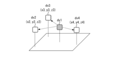
- the device dv1 in FIG. 10 is, for example, a mobile communication device such as a smartphone, and the devices dv2 to dv4 are, for example, beacon devices installed at a predetermined location. All of the devices dv1 to dv4 have the same configuration as the communication device 1 of FIG. 2, for example.
- the devices dv2 to dv4 send the information for calculating the distance, their own coordinates, and the altitude information to the device dv1.
- the information for calculating the distance is, for example, a single carrier signal.
- the device dv1 transmits a single carrier signal to each device dv2 to dv4, and the devices dv2 to dv4 return the same signal to the device dv1, so that the device dv1 has the distance information with each device dv2 to dv4 as described above. Can be calculated. Further, the devices dv2 to dv4 send their own coordinate information and altitude information to the device dv1. As a result, the device dv1 can perform highly accurate positioning regardless of the height of the device dv1 based on the distance information between the devices dv2 to dv4 and the altitude information of the devices dv2 to dv4.
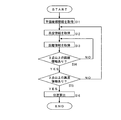
- FIG. 11 is a flowchart showing the processing operation of the device dv1.
- the plane coordinate information of the devices dv2 to dv4 is acquired (step S11).
- the own coordinate information of each device sent from the devices dv2 to dv4 is acquired.
- step S12 the altitude information of each device dv1 to dv4 is acquired. If the device dv1 includes the altitude sensor 10, the device dv1 acquires altitude information by the altitude sensor 10. In addition, the altitude information sent from the devices dv2 to dv4 is acquired.
- the distance information between the device dv1 and the devices dv2 to dv4 is acquired (step S13).
- the distance information can be calculated by reciprocating the signal for each frequency channel between the device dv1 and the devices dv2 to dv4, for example, in the phase-based method.
- the calculation of the distance information does not necessarily have to be performed by the device dv1, and the device dv1 may acquire the result of each of the devices dv2 to dv4 calculating the distance information with the device dv1.
- step S14 it is determined whether or not there is distance information of 3 points or more.
- step S14 it is determined whether or not there is distance information of three or more points, and if not, the process returns to step S13 to acquire new distance information.
- step S15 it is determined whether or not there is altitude information of 3 points or more.
- the altitude sensor 10 such as the barometric pressure sensor has high detection accuracy, and can reliably detect altitude information even in a multipath environment. Therefore, the accuracy of position detection can be improved by performing position detection using altitude information. Further, the larger the number of altitude information, the higher the accuracy of position detection.
- step S15 it is determined whether or not there is altitude information of 3 points or more, and if there is only altitude information of 3 points or less, step S12. Return to to obtain new altitude information, and if there are three or more points of altitude information, the position of the device dv1 is detected (step 16), and the process of FIG. 11 ends.
- the device dv1 acquires the information for calculating the distance, the own coordinate information, and the altitude information from the surrounding devices dv2 to dv4, respectively, based on the propagation channel characteristics.
- the distance information between the devices dv2 to dv4 can be calculated, and the position of the device dv1 can be accurately detected based on the coordinate information and altitude information of the devices dv2 to dv4.
- the position of the device dv1 is calculated by a processing device such as a server.
- the second embodiment mainly assumes flow line analysis and robot position grasping in a factory.
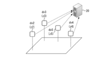
- the device dv1 in FIGS. 12A and 12B is a beacon device installed on a moving body such as a specific human or machine, and the devices dv2 to dv4 have a communication function with a beacon device or a server (processing device) installed in various places. Is a communication device 1 provided with.
- the devices dv1 to dv4 have the same configuration as that of FIG. 2, for example.
- the device dv1 transmits information for calculating the distance to the devices dv2 to dv4 in response to the request from the devices dv2 to dv4.
- the information for calculating the distance is, for example, a single carrier signal as described above.
- the altitude information measured by the altitude sensor 10 may be included in the information for calculating the distance and transmitted to the devices dv2 to dv4.
- the devices dv2 to dv4 calculate the distance information from the device dv1 based on the above-mentioned propagation channel characteristics. Then, as shown in FIG. 12B, the devices dv2 to dv4 transmit the calculated distance information, the own coordinate information, and the altitude information acquired by the altitude sensor 10 to the processing device 20 such as a server.
- the processing device 20 calculates the position of the device dv1 based on the distance information, the own coordinate information, and the altitude information transmitted from the devices dv2 to dv4.
- FIGS. 12A and 12B an example of calculating the position of the device dv1 using the devices dv2 to dv4 around the device dv1 is shown, but even when a plurality of devices dv1 exist, a plurality of devices dv1 around each device dv1.
- the positions of a plurality of devices dv1 can be calculated by the above-mentioned processing procedure.
- the specific form of the processing device 20 does not matter.
- the processing device 20 may have a communication function with the devices dv2 to dv4 and a processing performance for calculating the position of the device dv1, and may be a server, a PC, a tablet, or the like.
- the information for calculating the distance is transmitted from the device dv1 to the devices dv2 to dv4, the distance information with the device dv1 is calculated by the devices dv2 to dv4, and the devices dv2 to dv4. Transmits distance information, own coordinate information, and altitude information to the server, and the processing device 20 calculates the position of the device dv1.
- the position of the device dv1 can be managed by the processing device 20 such as a server. Further, even if the device dv1 does not have the processing performance for calculating the position, the processing device 20 can accurately calculate the position of the device dv1.
- a plurality of devices send and receive signals to each other, calculate distance information from each other, and transmit the calculated distance information to a processing device 20 such as a server.
- FIG. 13 is a block diagram showing a schematic configuration of the processing device 20 according to the third embodiment.
- the communication device 1 of FIG. 13 includes an antenna 2, a transmission unit 3, a reception unit 4, a distance acquisition unit 61, and a position detection unit 62.
- the distance acquisition unit 61 acquires the distance information calculated by the communication partner device based on the propagation channel characteristics by transmitting and receiving signals to and from the communication partner device.
- the communication partner device reciprocates a signal with the other communication partner device, and calculates the distance information with the other communication partner device based on the propagation channel characteristics.
- the position detection unit 62 detects the position information based on the distance information acquired by the distance acquisition unit 61.
- the processing device 20 of FIG. 13 may include an altitude sensor 10.
- the devices dv2 to dv5 are, for example, beacon devices, and have the same configuration as the communication device 1 of FIG.
- each device dv2 to dv5 is provided with the altitude sensor 10
- the devices dv2 to dv5 calculate the distance information based on the propagation channel characteristics by reciprocating the signal between the devices. Thereby, each of the devices dv2 to dv5 can calculate the relative coordinates.
- the devices dv2 to dv5 transmit the calculated distance information and altitude information to the processing device 20 such as a server.
- the processing device 20 has the configuration of FIG. 13, and can create a relative position map of the devices dv2 to dv5 based on the distance information and the altitude information transmitted from the devices dv2 to dv5.
- FIG. 15 is a flowchart showing the processing operation of the processing device 20 such as a server in FIG. 14B.
- the processing device 20 acquires the altitude information transmitted from the devices dv2 to dv5 (step S21) and also acquires the distance information (step S22).
- the processing device 20 determines whether or not the distance information of three points or more has been acquired (step S23), and if the distance information of less than three points has not been acquired yet, the processing of steps S22 and subsequent steps is performed. ..
- the processing device 20 determines whether or not the altitude information of three points or more has been acquired (step S24). If the distance information of less than 3 points has not been acquired yet, the processing of step S21 and subsequent steps is performed.
- the processing device 20 creates a three-dimensional map (step S25).
- the three-dimensional map is a map including relative position information of devices dv2 to dv5.
- the processing device 20 can acquire the absolute position (coordinates) coordinates of one or more points, it is possible to create a three-dimensional map including the absolute position (coordinates) information of the devices dv2 to dv5.
- the relative distance information can be calculated in each device based on the propagation channel characteristics by reciprocating the signal between the devices dv2 to dv5. Further, by transmitting the distance information and the altitude information from the devices dv2 to dv5 to the processing device 20, the processing device 20 can create a three-dimensional map.
- FIG. 16 is a plan layout diagram showing an example in which beacon devices are installed at a plurality of locations in the room.
- the black triangle mark in FIG. 16 is a reference beacon device 39a whose installation position is fixed.
- the white triangle mark is a beacon device 39b whose installation location can be changed.
- the distance calculated based on the propagation channel characteristics by reciprocating the signal between the beacon devices 39b or between the beacon device 39b and the reference beacon device 39a From the information, the position of each beacon device 39b can be detected.
- each beacon device 39b can be detected by a processing device 20 such as a server that acquires distance information and altitude information from each beacon device 39a and each reference beacon device 39b.
- a processing device 20 such as a server that acquires distance information and altitude information from each beacon device 39a and each reference beacon device 39b.
- FIG. 17 is a flowchart showing a first example of the processing operation of the communication system according to the fourth embodiment.
- the calibration mode refers to a mode in which the processing device 20 performs a process of updating the position of each beacon device 39b.
- the processing device 20 may shift to the calibration mode at the time of power-on or reset, may shift to the calibration mode when the user gives an explicit instruction, or may shift to the calibration mode at a predetermined time interval or not. You may shift to the calibration mode on a regular basis.
- each beacon device 39b and the processing device 20 operate in the normal mode (step S32).
- the normal mode is a mode for calculating or acquiring distance information with a moving body.
- the signals are reciprocated between the beacon devices 39b or between the beacon device 39b and the reference beacon device 39a to start distance measurement, and the relative distance is based on the propagation channel characteristics.
- the information is calculated (step S33).
- the calculated distance information is transmitted to the processing device 20 (step S34). If each beacon device 39b is equipped with an altitude sensor 10, altitude information is transmitted to the processing device 20.
- the processing device 20 starts the positioning calculation of each beacon device 39b based on the distance information and the altitude information (step S35). Based on the result of the positioning calculation, the processing device 20 updates the position information of each beacon device 39b (step S36).
- the updated coordinate information may be directly transmitted to each beacon device 39b, or the processing device 20 registers the position (coordinate) information of each beacon device 39b.
- a database may be possessed and the processing device 20 may manage the position of each beacon device 39b.
- each beacon device 39b may transmit information other than distance information and altitude information, for example, battery remaining amount information to the processing device 20.
- the processing device 20 can manage the battery status of each beacon device 39b, and the operator or the like can replace the battery before the battery runs out. Can be encouraged.
- FIG. 16 has described an example in which the reference beacon device 39a having a fixed installation location is provided, the reference beacon device 39a may be able to acquire absolute position (coordinate) information. GPS signals are difficult to obtain indoors, but they can often be obtained near windows. Therefore, as shown in FIG. 18, the reference beacon device 39a may be installed in the vicinity of the window 40 to acquire absolute position information. If the plurality of beacon devices 39b and the reference beacon device 39a include the reference beacon device 39a capable of acquiring absolute position information, all the beacon devices 39b and the reference beacon device 39a can acquire the absolute position information.
- FIG. 19 is a flowchart showing a second example of the processing operation of the communication system according to the fourth embodiment.
- the flowchart of FIG. 19 is obtained by adding step S37 to the flowchart of FIG. Step S37 is performed when it is determined in step S31 that the calibration mode is set.
- the reference beacon device 39a receives the GPS signal and acquires the absolute position information. After that, by performing the processes of steps S33 to S36, the processing device 20 can update the absolute position information of each beacon device 39b.
- the plurality of beacon devices 39b reciprocate the signals and transmit the distance information calculated based on the propagation channel characteristics to the processing device 20, so that the processing device 20 uses each of them.
- the position of the beacon device 39b can be updated.
- the fifth embodiment evaluates the reliability of the calculated value of the distance information.
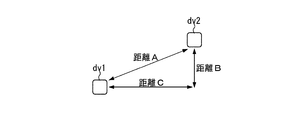
- FIG. 20A shows an example in which the device dv1 and the device dv2 are provided at the same altitude
- FIG. 20B is a diagram showing an example in which the altitudes of the device dv1 and the device dv2 are different.
- the distance A between the devices dv1 and dv2 is calculated to be 5 m.
- the distance A is calculated as 5 m and the altitude difference B is detected as 3 m by the altitude sensor 10.
- the horizontal distance C between the device dv1 and the device dv2 is calculated to be 4 m by the three-square theorem.
- the angle and horizontal distance can be obtained with only two devices. Using this information, the reliability of the calculation of the distance information can be set.
- FIG. 21 is a flowchart showing a first example of the processing operation of the communication system according to the fifth embodiment.
- This flowchart is executed by a processing device 20 such as a server.
- a signal is reciprocated between a plurality of devices to acquire distance information based on the propagation channel characteristics (step S41).
- altitude information from each device is acquired, and the angle and horizontal distance between the two devices are calculated based on the acquired altitude information and distance information (step S42).
- step S43 it is determined whether or not the angle and horizontal distance calculated in step S42 are within a reasonable range. If it is determined that the value is within a reasonable range, the acquired distance information is determined to have high reliability (step S44). On the other hand, if it is determined that the value is not within a reasonable range, the acquired distance information is determined to have low reliability (step S45).
- the horizontal distance is 0 m or less, so that the reliability is determined to be low. .. Further, even if the angle is calculated to be 90 degrees even though a plurality of devices are not arranged in the vertical direction, it is determined that the reliability is low.
- FIG. 22 is a flowchart showing a second example of the processing operation of the communication system according to the fifth embodiment. This flowchart is also executed by a processing device 20 such as a server.
- a processing device 20 such as a server.
- distance information of four or more points is acquired (step S51).
- the altitude information of 4 points or more is acquired (step S52).
- three points where the altitude information is close to each other are selected (step S53).
- the position is calculated based on the distance information of four or more points and the altitude information of the three selected points (step S54).
- step S53 three points where the altitude information is close to each other are selected from a large number of altitude information, because the closer the altitude value is, the larger the ratio of the horizontal distance to the distance between the two points is. Therefore, the distance between two points can be calculated more accurately.
- the reliability of the distance information calculated based on the propagation channel characteristics can be easily and accurately determined by using the altitude information.
- a method for calculating the distance information by the phase-based method has been mainly described, but other than the phase-based method.
- the distance information may be calculated by the method of.
- UWB In UWB, a predetermined frequency range is divided into a plurality of sub-bands, a multi-band signal is transmitted, and the propagation delay time of the signal between the transmitting unit 3 and the receiving unit 4 is estimated. The distance between the transmitting unit 3 and the receiving unit 4 can be calculated from the propagation delay time.
- the present technology can have the following configurations.
- a distance acquisition unit that acquires distance information calculated based on the propagation channel characteristics, and A communication device including an altitude acquisition unit for acquiring altitude information.
- the communication device according to (1) comprising a communication unit that transmits the distance information and the altitude information to the processing device.
- the communication device according to (1) or (2) wherein the distance acquisition unit acquires the distance information calculated from the relationship between the frequencies and phases of a plurality of propagation channels.
- the distance acquisition unit directly acquires the distance information from the measurement phase calculated based on the group delay calculated from the relationship between the frequencies and phases of the plurality of propagation channels, (1) or (2).
- the communication device (5) The communication device according to (1) or (2), wherein the distance acquisition unit acquires the distance information based on a UWB (Ultra WideBand) band radio signal. (6) The communication device according to (3) to (5), wherein the altitude acquisition unit acquires the altitude information based on the atmospheric pressure detected by the atmospheric pressure sensor. (7) The communication device according to (6), wherein the altitude acquisition unit acquires the altitude information based on the atmospheric pressure detected by the atmospheric pressure sensor and the temperature detected by the temperature sensor. (8) A distance acquisition unit that acquires a plurality of distance information calculated from the relationship between each frequency and phase of a plurality of propagation channels, and a distance acquisition unit.
- UWB Ultra WideBand
- the altitude acquisition unit that acquires altitude information by communication
- a processing device including a position detection unit that detects position information based on the distance information and the altitude information.
- the distance acquisition unit acquires three or more distance information regarding the distance between the object and the three or more communication partner devices, and obtains three or more distance information.
- the altitude acquisition unit acquires three or more of the altitude information from the three or more communication partner devices.
- the processing device according to (9), wherein the position detection unit detects the position of the object based on the three or more distance information and the three or more altitude information.
- the distance acquisition unit calculates the phase of the object by transmitting and receiving radio signals of a plurality of frequencies to and from the three or more communication partner devices, whereby the three or more communication partner devices of the object. Calculate the distance information with The position detection unit detects the position of the object based on the three or more distance information calculated by the distance acquisition unit and the three or more altitude information, according to (10). Processing equipment. (12) The distance acquisition unit acquires the three or more distance information calculated by the three or more communication partner devices when the object communicates with the three or more communication partner devices. The processing device according to (10), wherein the position detection unit detects the position of the object based on the three or more distance information acquired by the distance acquisition unit and the three or more altitude information. ..
- the processing apparatus according to (11) or (12), wherein the position detection unit creates a three-dimensional map showing position information in a predetermined three-dimensional space based on the distance information.
- the distance acquisition unit acquires three or more distance information between the object and the three or more communication partner devices, and obtains the distance information.
- the processing device according to (13), wherein the position detection unit creates the three-dimensional map based on the three or more distance information.
- the processing device according to (14), wherein the three-dimensional map includes position information of the object and the three or more communication partner devices.
- the distance acquisition unit acquires three or more distance information regarding the distance between the object and the three or more communication partner devices, and obtains three or more distance information.
- the altitude acquisition unit acquires three or more altitude information from the three or more communication partner devices, and obtains three or more altitude information.
- the processing device according to (15), wherein the position detection unit creates the three-dimensional map based on the three or more distance information and the three or more altitude information.
- a distance acquisition unit that acquires a plurality of distance information calculated from the relationship between each frequency and phase of a plurality of propagation channels, and a distance acquisition unit.
- a position acquisition unit that acquires at least one absolute position information
- a processing device including a position information detection unit that detects position information based on the plurality of distance information and absolute position information acquired by the position acquisition unit.
- the position acquisition unit acquires the absolute position information periodically or irregularly, and obtains the absolute position information.
- the processing device wherein the position detection unit updates the position information based on the absolute position information acquired by the position acquisition unit periodically or irregularly.
- the processing device Further equipped with an altitude acquisition unit that acquires altitude information by communication, The processing device according to (17) or (18), wherein the position detection unit detects the position information based on the plurality of distance information, the absolute position information, and the altitude information.
- the altitude information includes altitude difference information regarding the altitude difference between two points.
- the processing apparatus according to (19), further comprising a reliability estimation unit that estimates the reliability of the distance information based on the distance information and the altitude difference information.
- the communication device according to any one of (3) to (5), further comprising a position acquisition unit that acquires at least one absolute position information.
- the communication device according to (21), wherein the position acquisition unit acquires GPS (Global Positioning System) information.
- the altitude acquisition department that acquires altitude information and A communication system including a position detection unit that detects position information based on the distance information and the altitude information.
- a third communication device for transmitting and receiving wireless signals to and from the second communication device is provided.
- the second communication device has the distance acquisition unit and the altitude acquisition unit.
- the third communication device has the position detection unit and has the position detection unit.
- the distance acquisition unit acquires the distance information with the first communication device, and obtains the distance information.
- the communication system wherein the position detection unit detects the position information based on the distance information and the altitude information. (25) Acquire the distance information calculated based on the propagation channel characteristics, and Get altitude information, A communication method that detects position information based on the distance information and the altitude information.
- 1 communication device 2 antenna, 3 transmitter, 4 receiver, 5 distance acquisition, 6 altitude acquisition, 7 clock generator, 8 distance calculation, 9 altitude calculation, 10 altitude sensor, 11 initiator, 12 reflector, 13 Control unit, 20 Processing device, 30 Interface unit, 31 Low noise amplifier, 32 Mixer, 33 Bandpass filter, 34 Variable gain amplifier, 35 BPF, 36 VGA, 37 ADC, 41 Phase measurement unit, 43 RAM, 44 Automatic gain control Unit, 61 distance acquisition unit, 62 position detection unit
Landscapes
- Engineering & Computer Science (AREA)
- Radar, Positioning & Navigation (AREA)
- Remote Sensing (AREA)
- Physics & Mathematics (AREA)
- General Physics & Mathematics (AREA)
- Computer Networks & Wireless Communication (AREA)
- Signal Processing (AREA)
- Automation & Control Theory (AREA)
- Position Fixing By Use Of Radio Waves (AREA)
- Radar Systems Or Details Thereof (AREA)
Priority Applications (3)
| Application Number | Priority Date | Filing Date | Title |
|---|---|---|---|
| US17/796,754 US20230070913A1 (en) | 2020-03-25 | 2021-03-18 | Communication device, communication system, and communication method |
| KR1020227030345A KR20220158691A (ko) | 2020-03-25 | 2021-03-18 | 통신 장치, 통신 시스템 및 통신 방법 |
| JP2022510058A JP7698630B2 (ja) | 2020-03-25 | 2021-03-18 | 通信装置、通信システム及び通信方法 |
Applications Claiming Priority (2)
| Application Number | Priority Date | Filing Date | Title |
|---|---|---|---|
| JP2020054816 | 2020-03-25 | ||
| JP2020-054816 | 2020-03-25 |
Publications (1)
| Publication Number | Publication Date |
|---|---|
| WO2021193386A1 true WO2021193386A1 (ja) | 2021-09-30 |
Family
ID=77891777
Family Applications (1)
| Application Number | Title | Priority Date | Filing Date |
|---|---|---|---|
| PCT/JP2021/011254 Ceased WO2021193386A1 (ja) | 2020-03-25 | 2021-03-18 | 通信装置、通信システム及び通信方法 |
Country Status (4)
| Country | Link |
|---|---|
| US (1) | US20230070913A1 (https=) |
| JP (1) | JP7698630B2 (https=) |
| KR (1) | KR20220158691A (https=) |
| WO (1) | WO2021193386A1 (https=) |
Cited By (4)
| Publication number | Priority date | Publication date | Assignee | Title |
|---|---|---|---|---|
| WO2023085024A1 (ja) * | 2021-11-10 | 2023-05-19 | ソニーセミコンダクタソリューションズ株式会社 | 情報処理装置、情報処理方法、プログラム |
| WO2023100561A1 (ja) * | 2021-12-01 | 2023-06-08 | ソニーセミコンダクタソリューションズ株式会社 | 測距装置、測距方法 |
| JPWO2023248540A1 (https=) * | 2022-06-21 | 2023-12-28 | ||
| WO2025100095A1 (ja) * | 2023-11-08 | 2025-05-15 | ソニーセミコンダクタソリューションズ株式会社 | 通信装置、測位システム、および、通信装置の制御方法 |
Citations (7)
| Publication number | Priority date | Publication date | Assignee | Title |
|---|---|---|---|---|
| US5832369A (en) * | 1996-06-05 | 1998-11-03 | Wiltron Company | Microwave receiver configured to provide non-referenced distance measurements along with signal magnitude measurements |
| JP2000314771A (ja) * | 1999-04-30 | 2000-11-14 | Matsushita Electric Works Ltd | Gps利用情報システム |
| JP2009216474A (ja) * | 2008-03-08 | 2009-09-24 | Brother Ind Ltd | 移動局測位システム |
| US20160381504A1 (en) * | 2015-06-24 | 2016-12-29 | Apple Inc. | Positioning Techniques for Narrowband Wireless Signals Under Dense Multipath Conditions |
| JP2017122735A (ja) * | 2008-04-14 | 2017-07-13 | モジクス, インコーポレイティッド | 無線自動識別タグの位置を推定及び追跡するシステム並びに方法 |
| US20180270783A1 (en) * | 2017-03-16 | 2018-09-20 | Qualcomm Incorporated | Robust downlink positioning |
| CN110856106A (zh) * | 2019-11-20 | 2020-02-28 | 重庆邮电大学 | 基于uwb和气压计的室内高精度三维定位方法 |
Family Cites Families (10)
| Publication number | Priority date | Publication date | Assignee | Title |
|---|---|---|---|---|
| JP2011017685A (ja) | 2009-07-10 | 2011-01-27 | Kenwood Corp | 測位システム及び制御方法 |
| WO2011091062A1 (en) * | 2010-01-20 | 2011-07-28 | Worcester Polytechnic Institute | Precision location method and system |
| US10440512B2 (en) * | 2012-08-03 | 2019-10-08 | Polte Corporation | Angle of arrival (AOA) positioning method and system for positional finding and tracking objects using reduced attenuation RF technology |
| US10742475B2 (en) * | 2012-12-05 | 2020-08-11 | Origin Wireless, Inc. | Method, apparatus, and system for object tracking sensing using broadcasting |
| US9078102B2 (en) * | 2012-11-12 | 2015-07-07 | Qualcomm Incorporated | Techniques for generating environment and reference data reports for particular environments on behalf of mobile devices |
| US9689958B1 (en) * | 2013-03-20 | 2017-06-27 | Ben Wild | Device positioning using acoustic and radio signals |
| US10094905B2 (en) * | 2014-02-28 | 2018-10-09 | Qualcomm Incorporated | Opportunistic calibration of a barometer in a mobile device |
| JP2017067565A (ja) | 2015-09-29 | 2017-04-06 | 株式会社Nttドコモ | 端末装置および測位プログラム |
| US10805767B2 (en) * | 2016-12-15 | 2020-10-13 | Philips North America Llc | Method for tracking the location of a resident within a facility |
| US10602476B2 (en) * | 2018-08-01 | 2020-03-24 | Nextnav, Llc | Systems and methods for determining an indoor or outdoor location of a mobile device |
-
2021
- 2021-03-18 KR KR1020227030345A patent/KR20220158691A/ko active Pending
- 2021-03-18 WO PCT/JP2021/011254 patent/WO2021193386A1/ja not_active Ceased
- 2021-03-18 US US17/796,754 patent/US20230070913A1/en active Pending
- 2021-03-18 JP JP2022510058A patent/JP7698630B2/ja active Active
Patent Citations (7)
| Publication number | Priority date | Publication date | Assignee | Title |
|---|---|---|---|---|
| US5832369A (en) * | 1996-06-05 | 1998-11-03 | Wiltron Company | Microwave receiver configured to provide non-referenced distance measurements along with signal magnitude measurements |
| JP2000314771A (ja) * | 1999-04-30 | 2000-11-14 | Matsushita Electric Works Ltd | Gps利用情報システム |
| JP2009216474A (ja) * | 2008-03-08 | 2009-09-24 | Brother Ind Ltd | 移動局測位システム |
| JP2017122735A (ja) * | 2008-04-14 | 2017-07-13 | モジクス, インコーポレイティッド | 無線自動識別タグの位置を推定及び追跡するシステム並びに方法 |
| US20160381504A1 (en) * | 2015-06-24 | 2016-12-29 | Apple Inc. | Positioning Techniques for Narrowband Wireless Signals Under Dense Multipath Conditions |
| US20180270783A1 (en) * | 2017-03-16 | 2018-09-20 | Qualcomm Incorporated | Robust downlink positioning |
| CN110856106A (zh) * | 2019-11-20 | 2020-02-28 | 重庆邮电大学 | 基于uwb和气压计的室内高精度三维定位方法 |
Cited By (6)
| Publication number | Priority date | Publication date | Assignee | Title |
|---|---|---|---|---|
| WO2023085024A1 (ja) * | 2021-11-10 | 2023-05-19 | ソニーセミコンダクタソリューションズ株式会社 | 情報処理装置、情報処理方法、プログラム |
| WO2023100561A1 (ja) * | 2021-12-01 | 2023-06-08 | ソニーセミコンダクタソリューションズ株式会社 | 測距装置、測距方法 |
| JPWO2023248540A1 (https=) * | 2022-06-21 | 2023-12-28 | ||
| WO2023248540A1 (ja) * | 2022-06-21 | 2023-12-28 | アルプスアルパイン株式会社 | 測距装置 |
| JP7730997B2 (ja) | 2022-06-21 | 2025-08-28 | アルプスアルパイン株式会社 | 測距装置 |
| WO2025100095A1 (ja) * | 2023-11-08 | 2025-05-15 | ソニーセミコンダクタソリューションズ株式会社 | 通信装置、測位システム、および、通信装置の制御方法 |
Also Published As
| Publication number | Publication date |
|---|---|
| JPWO2021193386A1 (https=) | 2021-09-30 |
| JP7698630B2 (ja) | 2025-06-25 |
| KR20220158691A (ko) | 2022-12-01 |
| US20230070913A1 (en) | 2023-03-09 |
Similar Documents
| Publication | Publication Date | Title |
|---|---|---|
| JP7698630B2 (ja) | 通信装置、通信システム及び通信方法 | |
| US8963775B2 (en) | Tracking radio signal sources | |
| US12360225B2 (en) | Communication device and communication method | |
| US10222208B2 (en) | Apparatus, system and method of estimating an orientation of a mobile device | |
| US9587931B2 (en) | Position compensation device using visible light communication and method thereof | |
| CN103644905A (zh) | 一种情境相关的室内定位方法及系统 | |
| US10725181B2 (en) | In-band pseudolite wireless positioning method, system and device | |
| CN113194531A (zh) | 定位方法及通信设备 | |
| CN106714079B (zh) | 定位推播服务系统、使用者行动装置及定位推播服务方法 | |
| US10077985B2 (en) | Wireless positioning system, wireless positioning terminal, and point information transmitter | |
| JP2012506032A (ja) | 揺動構造物の動きを判定するシステム | |
| KR101135201B1 (ko) | 무선 네트워크에서 가속도 위치 정보를 이용한 수신신호강도 기반 위치 측정 방법 및 위치측정 시스템 | |
| EP2856199A1 (en) | Determining location and orientation of directional tranceivers | |
| EP4343377A1 (en) | Communication device and ranging method | |
| WO2022153773A1 (ja) | 通信装置、通信システム及び通信方法 | |
| US10557915B2 (en) | Providing an indication of a heading of a mobile device | |
| KR102138064B1 (ko) | 실내 측위 시스템 및 이를 이용한 실내 위치 측위 방법 | |
| JP2019178974A (ja) | 移動端末の位置測位方法、通信装置、及び、移動端末 | |
| JP2017032486A (ja) | 携帯端末の位置測定システム、携帯端末及び位置測定プログラム | |
| KR20200000882A (ko) | 상대위치측정장치 및 상대위치측정시스템 | |
| WO2025100095A1 (ja) | 通信装置、測位システム、および、通信装置の制御方法 | |
| JP6771348B2 (ja) | 無線通信システム | |
| CN120343487A (zh) | 定位方法及装置、计算机可读存储介质 | |
| KR20250164489A (ko) | 센서 데이터 융합을 이용한 연속측위 장치 | |
| WO2024072324A1 (en) | Device, positioning system and method of determining a position of the device for vehicular communication |
Legal Events
| Date | Code | Title | Description |
|---|---|---|---|
| 121 | Ep: the epo has been informed by wipo that ep was designated in this application |
Ref document number: 21774105 Country of ref document: EP Kind code of ref document: A1 |
|
| ENP | Entry into the national phase |
Ref document number: 2022510058 Country of ref document: JP Kind code of ref document: A |
|
| NENP | Non-entry into the national phase |
Ref country code: DE |
|
| 122 | Ep: pct application non-entry in european phase |
Ref document number: 21774105 Country of ref document: EP Kind code of ref document: A1 |
|
| WWW | Wipo information: withdrawn in national office |
Ref document number: 1020227030345 Country of ref document: KR |