WO2021192782A1 - 寸法計測方法及び寸法計測装置 - Google Patents
寸法計測方法及び寸法計測装置 Download PDFInfo
- Publication number
- WO2021192782A1 WO2021192782A1 PCT/JP2021/006668 JP2021006668W WO2021192782A1 WO 2021192782 A1 WO2021192782 A1 WO 2021192782A1 JP 2021006668 W JP2021006668 W JP 2021006668W WO 2021192782 A1 WO2021192782 A1 WO 2021192782A1
- Authority
- WO
- WIPO (PCT)
- Prior art keywords
- line segment
- dimension
- user
- line
- model
- Prior art date
- Legal status (The legal status is an assumption and is not a legal conclusion. Google has not performed a legal analysis and makes no representation as to the accuracy of the status listed.)
- Ceased
Links
Images










Classifications
-
- G—PHYSICS
- G01—MEASURING; TESTING
- G01B—MEASURING LENGTH, THICKNESS OR SIMILAR LINEAR DIMENSIONS; MEASURING ANGLES; MEASURING AREAS; MEASURING IRREGULARITIES OF SURFACES OR CONTOURS
- G01B11/00—Measuring arrangements characterised by the use of optical techniques
- G01B11/02—Measuring arrangements characterised by the use of optical techniques for measuring length, width or thickness
-
- G—PHYSICS
- G01—MEASURING; TESTING
- G01C—MEASURING DISTANCES, LEVELS OR BEARINGS; SURVEYING; NAVIGATION; GYROSCOPIC INSTRUMENTS; PHOTOGRAMMETRY OR VIDEOGRAMMETRY
- G01C11/00—Photogrammetry or videogrammetry, e.g. stereogrammetry; Photographic surveying
- G01C11/02—Picture taking arrangements specially adapted for photogrammetry or photographic surveying, e.g. controlling overlapping of pictures
- G01C11/025—Picture taking arrangements specially adapted for photogrammetry or photographic surveying, e.g. controlling overlapping of pictures by scanning the object
-
- G—PHYSICS
- G01—MEASURING; TESTING
- G01C—MEASURING DISTANCES, LEVELS OR BEARINGS; SURVEYING; NAVIGATION; GYROSCOPIC INSTRUMENTS; PHOTOGRAMMETRY OR VIDEOGRAMMETRY
- G01C11/00—Photogrammetry or videogrammetry, e.g. stereogrammetry; Photographic surveying
- G01C11/04—Interpretation of pictures
- G01C11/30—Interpretation of pictures by triangulation
-
- G—PHYSICS
- G06—COMPUTING OR CALCULATING; COUNTING
- G06T—IMAGE DATA PROCESSING OR GENERATION, IN GENERAL
- G06T17/00—Three-dimensional [3D] modelling for computer graphics
-
- G—PHYSICS
- G06—COMPUTING OR CALCULATING; COUNTING
- G06T—IMAGE DATA PROCESSING OR GENERATION, IN GENERAL
- G06T7/00—Image analysis
- G06T7/10—Segmentation; Edge detection
- G06T7/12—Edge-based segmentation
-
- G—PHYSICS
- G06—COMPUTING OR CALCULATING; COUNTING
- G06T—IMAGE DATA PROCESSING OR GENERATION, IN GENERAL
- G06T7/00—Image analysis
- G06T7/10—Segmentation; Edge detection
- G06T7/13—Edge detection
-
- G—PHYSICS
- G06—COMPUTING OR CALCULATING; COUNTING
- G06T—IMAGE DATA PROCESSING OR GENERATION, IN GENERAL
- G06T7/00—Image analysis
- G06T7/50—Depth or shape recovery
- G06T7/55—Depth or shape recovery from multiple images
- G06T7/564—Depth or shape recovery from multiple images from contours
-
- G—PHYSICS
- G06—COMPUTING OR CALCULATING; COUNTING
- G06T—IMAGE DATA PROCESSING OR GENERATION, IN GENERAL
- G06T7/00—Image analysis
- G06T7/60—Analysis of geometric attributes
- G06T7/62—Analysis of geometric attributes of area, perimeter, diameter or volume
-
- G—PHYSICS
- G06—COMPUTING OR CALCULATING; COUNTING
- G06V—IMAGE OR VIDEO RECOGNITION OR UNDERSTANDING
- G06V10/00—Arrangements for image or video recognition or understanding
- G06V10/40—Extraction of image or video features
- G06V10/44—Local feature extraction by analysis of parts of the pattern, e.g. by detecting edges, contours, loops, corners, strokes or intersections; Connectivity analysis, e.g. of connected components
-
- G—PHYSICS
- G06—COMPUTING OR CALCULATING; COUNTING
- G06V—IMAGE OR VIDEO RECOGNITION OR UNDERSTANDING
- G06V10/00—Arrangements for image or video recognition or understanding
- G06V10/70—Arrangements for image or video recognition or understanding using pattern recognition or machine learning
- G06V10/74—Image or video pattern matching; Proximity measures in feature spaces
- G06V10/761—Proximity, similarity or dissimilarity measures
-
- G—PHYSICS
- G06—COMPUTING OR CALCULATING; COUNTING
- G06V—IMAGE OR VIDEO RECOGNITION OR UNDERSTANDING
- G06V20/00—Scenes; Scene-specific elements
- G06V20/60—Type of objects
- G06V20/64—Three-dimensional [3D] objects
- G06V20/647—Three-dimensional [3D] objects by matching two-dimensional images to three-dimensional objects
-
- H—ELECTRICITY
- H04—ELECTRIC COMMUNICATION TECHNIQUE
- H04N—PICTORIAL COMMUNICATION, e.g. TELEVISION
- H04N23/00—Cameras or camera modules comprising electronic image sensors; Control thereof
- H04N23/60—Control of cameras or camera modules
- H04N23/63—Control of cameras or camera modules by using electronic viewfinders
- H04N23/633—Control of cameras or camera modules by using electronic viewfinders for displaying additional information relating to control or operation of the camera
-
- H—ELECTRICITY
- H04—ELECTRIC COMMUNICATION TECHNIQUE
- H04N—PICTORIAL COMMUNICATION, e.g. TELEVISION
- H04N23/00—Cameras or camera modules comprising electronic image sensors; Control thereof
- H04N23/60—Control of cameras or camera modules
- H04N23/64—Computer-aided capture of images, e.g. transfer from script file into camera, check of taken image quality, advice or proposal for image composition or decision on when to take image
-
- G—PHYSICS
- G06—COMPUTING OR CALCULATING; COUNTING
- G06T—IMAGE DATA PROCESSING OR GENERATION, IN GENERAL
- G06T2210/00—Indexing scheme for image generation or computer graphics
- G06T2210/04—Architectural design, interior design
Definitions
- This disclosure relates to a dimensional measurement method and a dimensional measurement device.
- Patent Document 1 discloses a method of calculating a structure shape by performing point cloud measurement by a multi-viewpoint image measurement method based on a plurality of images.
- An object of the present disclosure is to provide a dimensional measurement method or a dimensional measurement device capable of reducing a processing amount.
- a line segment model which is a three-dimensional model of the target area represented by a line, is generated by using a plurality of images of the target area taken from a plurality of viewpoints. Using the line segment model, the dimensions of a predetermined location in the target area are calculated, and the calculated dimensions are output.
- the present disclosure can provide a dimensional measurement method or a dimensional measurement device capable of reducing the processing amount.
- FIG. 1 is a diagram showing an example of dimensional measurement according to an embodiment.
- FIG. 2 is a diagram showing an example of dimensional measurement according to the embodiment.
- FIG. 3 is a block diagram of the dimension measuring device according to the embodiment.
- FIG. 4 is a block diagram of the imaging unit according to the embodiment.
- FIG. 5 is a block diagram of the control unit according to the embodiment.
- FIG. 6 is a block diagram of the dimension measurement unit according to the embodiment.
- FIG. 7 is a sequence diagram of the dimension measurement process according to the embodiment.
- FIG. 8 is a diagram showing an example of image capture according to the embodiment.
- FIG. 9 is a flowchart of the line segment reconstruction process according to the embodiment.
- FIG. 10 is a schematic diagram for explaining the line segment reconstruction according to the embodiment.
- FIG. 10 is a schematic diagram for explaining the line segment reconstruction according to the embodiment.
- FIG. 11 is a schematic diagram for explaining the line segment reconstruction according to the embodiment.
- FIG. 12 is a schematic diagram for explaining the line segment reconstruction according to the embodiment.
- FIG. 13 is a diagram showing a screen example according to the embodiment.
- FIG. 14 is a diagram showing a screen example according to the embodiment.
- FIG. 15 is a diagram showing a screen example according to the embodiment.
- FIG. 16 is a diagram showing a screen example according to the embodiment.
- FIG. 17 is a diagram showing a screen example according to the embodiment.
- FIG. 18 is a flowchart of the dimension measurement process according to the embodiment.
- FIG. 19 is a diagram showing a screen example according to the embodiment.
- FIG. 20 is a diagram showing a screen example according to the embodiment.
- FIG. 21 is a flowchart of the dimension measurement process according to the embodiment.
- a line segment model which is a three-dimensional model of the target area represented by a line, is generated by using a plurality of images of the target area taken from a plurality of viewpoints. Using the line segment model, the dimensions of a predetermined location in the target area are calculated, and the calculated dimensions are output.
- the dimension measurement method can reduce the processing amount by calculating the dimension using the line segment model. For example, as compared with the case where the shape of the target area is represented by a point cloud, the amount of processing can be reduced by expressing only the edge of the target area with a line. Specifically, in the dimensional measurement method using a three-dimensional model in which not only the edge of the target area but also the surface of the target area is represented by a point cloud, in order to measure the edge of the target area, the edge from the three-dimensional model is used. It is necessary to extract only the point cloud that represents.
- the line segment model since the line segment model includes only the point cloud representing the edge of the target region, it is not necessary to extract the point cloud representing the edge. Further, the amount of data of the line segment model according to one aspect of the present disclosure is smaller than the amount of data of the three-dimensional model in which the surface of the target region is also represented by a point cloud.
- the dimension measurement method further displays a user interface including the line segment model, and the predetermined location is formed on a plurality of lines included in the line segment model designated by the user via the user interface. It may be decided based on.
- the user when the user selects a plurality of lines from the line segment model, the dimensions of a predetermined location based on the selected multiple lines are measured. Therefore, the user can easily measure the dimensions of the desired portion.
- the dimension may be the distance between two lines selected by the user via the user interface.
- the user when the user selects two lines from the line segment model, the distance between the two selected lines is measured. Therefore, the user can easily measure the dimensions of the desired portion.
- the dimension may be the distance between a line and a surface selected by the user via the user interface.
- the user when the user selects a plurality of lines from the line segment model, the distance between the line and the surface based on the selected multiple lines is measured. Therefore, the user can easily measure the dimensions of the desired portion.
- the surface may be a surface defined by two lines selected by the user via the user interface.
- the user can easily select the desired surface.
- the user may be presented with a message prompting the user to photograph the entire object.
- the dimension measurement method can generate a line segment model using an image of the entire object, so that the accuracy of the line segment model can be improved. Therefore, the dimension measurement method can improve the accuracy of the dimension measurement.
- the line may be a line segment.
- the dimension measurement method can improve the accuracy of the line segment model because a line segment model can be generated using a line segment having both ends without using a part that is cut off in the image.
- the dimension measuring device includes a processor and a memory, and the processor is represented by a line segment using a plurality of images obtained by photographing the target area using the memory.
- a line segment model which is a three-dimensional model of the target area, is generated, the dimensions of a predetermined location in the target area are calculated using the line segment model, and the calculated dimensions are output.
- the dimension measuring device can reduce the processing amount by calculating the dimension using the line segment model.
- the dimension measuring device includes an input interface, a processor, and an output interface.
- a plurality of images obtained by capturing the target area from a plurality of viewpoints are input to the input interface.
- the processor generates a three-dimensional model in which the target area is represented by a line based on a plurality of images.
- the processor calculates the dimensions of a predetermined location in the 3D model. The calculated dimensions are output from the output interface.
- a recording medium such as a system, method, integrated circuit, computer program or computer-readable CD-ROM, and the system, method, integrated circuit, computer program. And any combination of recording media may be realized.
- FIG. 1 and 2 are diagrams showing an example of dimensional measurement.
- FIG. 1 shows an example of a kitchen, for example, the height L1 of the kitchen counter and the distance L2 from the floor to the outlet are measured.
- both L1 and L2 are defined as the distance between a surface and a line.
- L1 is the distance between the floor (face) and one side (line) of the counter.
- FIG. 2 shows an example of the entrance, for example, the undercut L3 (distance between the floor and the lower side of the door) of the door, the width L4 of the tile, and the gap L5 of the door are measured.
- L3 is the distance between lines
- L4 and L5 are the distances between lines.
- the distance between the line and the line or the distance between the line and the surface is measured.
- FIG. 3 is a block diagram of the dimension measuring device 100 according to the present embodiment.
- the dimension measuring device 100 includes an imaging unit 200, a control unit 300, a dimension measuring unit 400, and a user interface 500.
- the dimension measuring device 100 is included in a mobile terminal such as a tablet terminal or a smartphone.
- the imaging unit 200 captures an image (moving image or still image).
- the control unit 300 controls the image pickup unit 200, the dimension measurement unit 400, and the user interface 500.
- the dimension measurement unit 400 generates a line segment model, which is a three-dimensional model represented by a line segment, by reconstructing the line segment using the image taken by the image pickup unit 200.
- the line segment model is a three-dimensional model obtained by removing shapes (for example, faces) other than line segments.
- the dimension measurement unit 400 measures the dimension (distance) of the portion designated by the user by using the line segment model.
- the three-dimensional model is a computer representation of the imaged measurement target.
- the three-dimensional model has, for example, position information of each three-dimensional location on the measurement target.
- the line segment model is not limited to the line segment, and may be a three-dimensional model represented by a line.
- the line is a line segment having both ends, a half straight line having only one end, a straight line having no end, or a combination thereof. Further, having no edge means, for example, that the image is cut off.
- the user interface 500 accepts user input.
- the user interface 500 presents information to the user.
- the user interface 500 is a display and a touch panel.
- the user interface 500 is not limited to this, and may be any user interface.
- the user interface 500 may include a microphone, a speaker, and the like.
- FIG. 4 is a block diagram showing the configuration of the imaging unit 200.
- the imaging unit 200 includes a camera 201 and a gantry 202.
- the camera 201 includes a storage unit 211, a control unit 212, an optical system 213, and an image sensor 214.
- the storage unit 211 stores an image or the like taken by the image sensor 214.
- the control unit 212 controls the storage unit 211, the optical system 213, and the image sensor 214.
- the optical system 213 includes a lens or the like that causes light to enter the image sensor 214.
- the image sensor 214 captures an image.
- the gantry 202 controls the shooting direction of the camera 201.
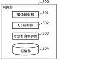
- FIG. 5 is a block diagram showing the configuration of the control unit 300.
- the control unit 300 includes an image pickup control unit 301, a UI control unit 302, a dimension measurement control unit 303, and a storage unit 304.
- the image pickup control unit 301 controls the image pickup unit 200.
- the UI control unit 302 controls the user interface 500.
- the dimension measurement control unit 303 controls the dimension measurement unit 400.
- the storage unit 304 stores an image taken by the image pickup unit 200, a line segment model generated by the dimension measurement unit 400, and the like.
- FIG. 6 is a block diagram showing the configuration of the dimension measurement unit 400.
- the dimension measurement unit 400 includes an image acquisition unit 401, a preprocessing unit 402, a line segment reconstruction unit 403, a plane estimation unit 404, and a measurement unit 405.
- the image acquisition unit 401 acquires a plurality of images taken by the image pickup unit 200.
- the preprocessing unit 402 preprocesses the acquired plurality of images.
- the line segment reconstruction unit 403 generates a line segment model by performing line segment reconstruction using a plurality of images after preprocessing.
- the plane estimation unit 404 estimates the plane included in the line segment model.
- the measuring unit 405 measures the distance between the line segments or the distance between the line segment and the surface by using the line segment model.
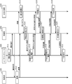
- FIG. 7 is a sequence diagram of the dimension measurement process in the dimension measurement device 100. This example is an example of measuring the distance between a line segment and a surface.
- the user gives an instruction to start shooting via the user interface (S11). For example, a start instruction is given by selecting a menu on the screen, starting an application, or the like.
- the control unit 300 When the control unit 300 receives the start instruction, the control unit 300 sends an imaging instruction to the imaging unit 200.
- the imaging unit 200 captures a plurality of images (still images) according to the imaging instruction (S12).
- the plurality of images (still images) obtained are two or more images of the same object (or target space) taken from different viewpoints.
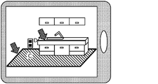
- FIG. 8 is a diagram showing an example of capturing the plurality of images.
- a user uses a single imaging device (eg, a tablet terminal) to capture images of an object (eg, a kitchen) from different positions.
- the imaging unit 200 does not necessarily have to be included in the dimension measuring device 100, and may be included in a terminal different from the terminal including the dimension measuring device 100. In this case, the image taken by the imaging unit 200 is sent to the dimension measuring device 100 via an arbitrary communication means such as wireless communication.
- the plurality of images may be a plurality of images taken by a plurality of fixed cameras. Further, the plurality of images may be images of two viewpoints taken by a stereo camera from one position. Further, the plurality of images may be a plurality of frames included in a moving image taken while moving by a single camera. Further, the plurality of images may be a combination of these.
- the plurality of captured images are sent to the dimension measurement unit 400 via the control unit 300.
- the dimension measurement unit 400 generates a line segment model by performing line segment reconstruction using a plurality of images (S13).
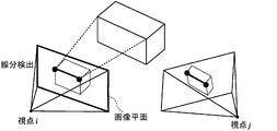
- FIG. 9 is a flowchart of the line segment reconstruction process (S13). Further, FIGS. 10 to 12 are schematic views for explaining the line segment reconstruction.
- the dimension measurement unit 400 detects a line segment included in each of the plurality of images (S31). Next, the dimension measurement unit 400 calculates the feature amount of each line segment (S32). Next, as shown in FIG. 11, the dimension measurement unit 400 uses the calculated feature amount to match line segments between images (S33). That is, the dimension measurement unit 400 detects a corresponding line segment which is a corresponding (same) line segment between images. Next, as shown in FIG. 12, the dimensional measurement unit 400 performs a geometric calculation using the relationship of the corresponding line segment to obtain the camera parameters (three-dimensional position and orientation) of each image and the three-dimensional line segment. The position is estimated (S34).
- the dimension measurement unit 400 generates a three-dimensional model represented by point cloud data (point cloud) using a plurality of images, and detects a line segment included in the generated three-dimensional model to obtain a line segment. You may generate a model.
- the line segment model generated by the line segment reconstruction (S13) is sent to the control unit 300.
- the control unit 300 generates a line segment model image of the line segment model viewed from a predetermined direction using the line segment model, and sends the line segment model image to the user interface (S14).
- the user interface 500 displays a UI (user interface) including a line segment model image.
- FIG. 13 is a diagram showing an example of this screen.
- the user may change the viewpoint position and enlarge / reduce the screen on the screen. That is, the viewpoint of the displayed linear model may be operable by the user.
- the linear model image may be superimposed and displayed on the image. This image may be a real-time image currently being captured, or may be an image captured in the past. That is, the viewpoint of the displayed linear model may be the same as the viewpoint of the image on which the linear model is superimposed.
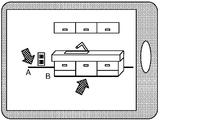
- FIG. 14 is a diagram showing an example of this screen.
- line segment A and line segment B are selected.
- Information indicating the selected line segment is sent to the dimension measurement unit 400 via the control unit 300.
- the dimension measurement unit 400 estimates a plane including the selected plurality of line segments based on the information of the selected plurality of line segments (S16). For example, as shown in FIG. 15, a surface C (floor) including a line segment A and a line segment B is detected. Information on the estimated plane is sent to the control unit 300. The control unit 300 superimposes the plane information on the line segment model image and outputs the obtained image to the user interface (S17).
- the user interface 500 displays the received image.
- the user selects a line segment and a surface to be dimensioned on the screen (S18).
- FIG. 16 is a diagram showing an example of this screen. In the example shown in FIG. 16, the line segment D and the surface C are selected.
- the plane may not be selected by the user and the plane may be automatically selected.
- the user may be asked if the plane may be selected.
- the plane estimation may be automatically performed by the dimension measurement unit 400 using the captured image or, if a point cloud model is generated, the point cloud model. In this case, since a plurality of planes are estimated, the user selects a plane to be dimensioned from the plurality of planes.
- the information of the selected dimension measurement target is sent to the dimension measurement unit 400.
- the dimension measurement unit 400 measures the dimension of the dimension measurement target using the line segment model (S19). Specifically, the dimension measuring unit 400 measures the distance between the selected line segment and the surface using the line segment model.
- the distance between the line segment and the surface is, for example, the minimum distance between the line segment and the surface.
- the result of the dimensional measurement is sent to the control unit 300.
- the control unit 300 generates dimensional information indicating the result of the dimensional measurement and sends it to the user interface 500 (S20).
- the user interface displays dimensional information (S21).
- FIG. 17 is a diagram showing an example of this screen. As shown in FIG. 17, information indicating a portion where the dimension is measured and the dimension (distance) are displayed.
- the minimum distance between one point (for example, the center point) on the line segment and the surface may be calculated.
- the minimum distances of the plurality of points and the surfaces on the line segment may be calculated, and the average value or the median value of the calculated minimum distances may be calculated.
- a plurality of the minimum value, the maximum value, the average value, and the median value of the plurality of minimum distances may be calculated and the calculated values may be presented to the user. Further, the user may be notified that the line segment and the surface are not parallel to each other.
- the distance between two line segments may be measured.
- S15 to S17 are not performed, and two line segments to be dimensioned are selected in S18.
- the distance between the two surfaces may be measured.
- two surfaces are estimated by performing S15 to S17 twice.
- a point and a line segment or a point and a surface may be specified by the user, and the distance between the point and the line segment or the distance between the point and the surface may be measured.
- the dimension measuring device 100 has a function of measuring the distance between a line segment and a surface, a function of measuring the distance between a line segment and a line segment, and other functions (surface and surface, point and line segment or point and the like. It may have only one of (functions of measuring the distance between surfaces), or may have a plurality of functions. When having a plurality of functions, which function is used may be specified by the user at a predetermined timing (for example, at the start of S11 or S15), or the user may specify at an arbitrary timing. May be specified by. Alternatively, the function may be automatically switched according to the selection result of the line segment or the surface of the user.
- the distance between the two line segments is measured, and when the user selects a line segment and a surface as dimension measurement targets, the distance between the two line segments is measured.
- the distance between the line segment and the surface may be measured.
- FIG. 18 is a flowchart of the dimension measurement process by the dimension measurement unit 400.
- the image acquisition unit 401 acquires a plurality of images captured by the image pickup unit 200 (S41).
- the preprocessing unit 402 executes preprocessing on the acquired plurality of images (S42).
- the preprocessing is, for example, brightness adjustment, noise removal, resolution conversion, color space conversion, lens distortion correction, projection conversion, affine transformation, edge enhancement processing, trimming processing, or a combination thereof.
- the timing at which the preprocessing is executed may be performed in accordance with the timing at which the dimension measurement processing is executed, or may be performed in advance.
- the plurality of preprocessed images obtained by executing the image preprocessing by the preprocessing unit 402 may be stored in the storage unit 304 included in the control unit 300.
- the preprocessing by the preprocessing unit 402 does not have to be executed. Therefore, the dimension measurement unit 400 does not have to include the pretreatment unit 402.
- the line segment reconstruction unit 403 performs line segment reconstruction to calculate the three-dimensional shape of a predetermined space using a plurality of images taken by the imaging unit 200 (S43). Specifically, the line segment reconstruction unit 403 detects a line segment for each of a plurality of images, associates the images with each other, and uses a correspondence relationship to perform a geometric calculation to obtain a predetermined space. Calculate a line segment model that is a three-dimensional line segment.
- the plane estimation unit 404 estimates a three-dimensional plane using a line segment model. First, the plane estimation unit 404 selects a plurality of line segments included in the plane in order to estimate the plane (S44). For example, the plurality of line segments are selected based on a user operation. The plane estimation unit 404 may automatically make this selection. Next, the plane estimation unit 404 estimates a plane including a plurality of selected line segments (S45). The plane estimation process by the plane estimation unit 404 does not have to be executed. Therefore, the dimension measurement unit 400 does not have to include the plane estimation unit 404.
- the measurement unit 405 selects two line segments or line segments and surfaces to be dimensioned (S46). For example, this selection is based on user interaction. The measurement unit 405 may automatically make this selection. Next, the measuring unit 405 calculates the two selected line segments or the distance between the line segment and the surface (S47). Further, the calculated distance is displayed on the user interface 500, for example.
- the dimension measuring device 100 may instruct the user to perform re-imaging in such a case. For example, the dimension measuring device 100 detects an edge in an image, and if the detected edge continues to the edge of the image, determines that the edge (object) is cut off.
- FIG. 19 is a diagram showing an example of a screen in which the entire object (kitchen counter) does not fit in the image.
- FIG. 20 is a diagram showing an example of a screen on which a message is displayed in this case. It should be noted that such a message may be displayed after the still image is shot, may be displayed while the real-time image before the still image is shot is displayed on the monitor, or may be displayed during the shooting of the moving image. You may. Further, such a warning to the user may be given by displaying an icon or by voice.
- the dimension measuring device 100 selects two or more images showing the entire object from the plurality of images.
- the line segment reconstruction may be performed using the two or more images. That is, the dimension measuring device 100 may perform line segment reconstruction without using an image in which the object is cut off.
- the dimension measuring device performs the process shown in FIG.
- the dimension measuring device generates a line segment model which is a three-dimensional model of the target area represented by a line by using a plurality of images of the target area taken from a plurality of viewpoints (S51).
- the dimension measuring device calculates the dimension of a predetermined place in the target area by using the line segment model (S52).
- the dimension measuring device outputs the calculated dimension (S53).
- the dimension measuring device 100 presents the calculated dimension to the user or outputs the calculated dimension to another device.
- the dimension measuring device can reduce the processing amount by calculating the dimension using the line segment model. Further, for example, the selection operation by the user can be facilitated as compared with the case where the user needs to select two points. Specifically, in order to accurately measure the height L1 of the kitchen counter shown in FIG. 1 by designating two points, the user needs to specify the two points closest to the floor and the upper surface of the kitchen counter. be. On the other hand, when a line and a line or a line and a surface are specified as in the present embodiment, the shortest distance between the line and the line or the line and the surface is automatically measured, so that the user can select the line and the surface. Becomes easier.
- the dimension measuring device further displays a user interface including a line segment model, and a predetermined location is determined based on a plurality of lines included in the line segment model specified by the user via the user interface.
- a predetermined location is determined based on a plurality of lines included in the line segment model specified by the user via the user interface.
- the dimension of a predetermined location is the distance between two lines selected by the user via the user interface. According to this, when the user selects two lines from the line segment model, the distance between the two selected lines is measured. Therefore, the user can easily measure the dimensions of the desired portion.
- the dimension of a predetermined location is the distance between a line and a surface selected by the user via the user interface. According to this, when the user selects a plurality of lines from the line segment model, the distance between the line and the surface based on the selected plurality of lines is measured. Therefore, the user can easily measure the dimensions of the desired portion.
- a surface selected by the user is a surface defined by two lines selected by the user via the user interface. According to this, the user can easily select the desired surface.
- the dimension measuring device can generate a line segment model using an image of the entire object, so that the accuracy of the line segment model can be improved. Therefore, the dimension measuring device can improve the accuracy of the dimension measurement.
- the above line is a line segment.
- the dimension measuring device can generate a line segment model by using a line segment having both ends without using a part that is cut off in the image, so that the accuracy of the line segment model can be improved.
- the dimension measuring device includes a processor and a memory, and the processor performs the above processing using the memory.
- each processing unit included in the dimension measuring device or the like according to the above embodiment is typically realized as an LSI which is an integrated circuit. These may be individually integrated into one chip, or may be integrated into one chip so as to include a part or all of them.
- the integrated circuit is not limited to the LSI, and may be realized by a dedicated circuit or a general-purpose processor.
- An FPGA Field Programmable Gate Array
- a reconfigurable processor that can reconfigure the connection and settings of the circuit cells inside the LSI may be used.
- each component may be configured by dedicated hardware or may be realized by executing a software program suitable for each component.
- Each component may be realized by a program execution unit such as a CPU or a processor reading and executing a software program recorded on a recording medium such as a hard disk or a semiconductor memory.
- the present disclosure may be realized as a dimension measurement method or the like executed by a dimension measurement device or the like.
- the division of the functional block in the block diagram is an example, and a plurality of functional blocks can be realized as one functional block, one functional block can be divided into a plurality of functional blocks, and some functions can be transferred to other functional blocks. You may. Further, the functions of a plurality of functional blocks having similar functions may be processed by a single hardware or software in parallel or in a time division manner.
- each step in the flowchart is executed is for exemplifying in order to specifically explain the present disclosure, and may be an order other than the above. Further, a part of the above steps may be executed at the same time (parallel) as other steps.
- the present disclosure is not limited to this embodiment. As long as the gist of the present disclosure is not deviated, various modifications that can be conceived by those skilled in the art are applied to the present embodiment, and a form constructed by combining components in different embodiments is also within the scope of one or more embodiments. May be included within.
- This disclosure can be applied to a dimensional measuring device.
Landscapes
- Engineering & Computer Science (AREA)
- Physics & Mathematics (AREA)
- General Physics & Mathematics (AREA)
- Theoretical Computer Science (AREA)
- Computer Vision & Pattern Recognition (AREA)
- Multimedia (AREA)
- Software Systems (AREA)
- Geometry (AREA)
- Artificial Intelligence (AREA)
- General Health & Medical Sciences (AREA)
- Medical Informatics (AREA)
- Evolutionary Computation (AREA)
- Databases & Information Systems (AREA)
- Computing Systems (AREA)
- Computer Graphics (AREA)
- Health & Medical Sciences (AREA)
- Radar, Positioning & Navigation (AREA)
- Remote Sensing (AREA)
- Signal Processing (AREA)
- Length Measuring Devices By Optical Means (AREA)
Priority Applications (4)
| Application Number | Priority Date | Filing Date | Title |
|---|---|---|---|
| CN202180018963.2A CN115210529A (zh) | 2020-03-24 | 2021-02-22 | 尺寸测量方法及尺寸测量装置 |
| EP21775971.1A EP4130648A4 (en) | 2020-03-24 | 2021-02-22 | DIMENSION MEASURING METHOD AND DIMENSION MEASURING DEVICE |
| JP2022509429A JP7710158B2 (ja) | 2020-03-24 | 2021-02-22 | 寸法計測方法及び寸法計測装置 |
| US17/942,548 US12584727B2 (en) | 2020-03-24 | 2022-09-12 | Dimension measurement method and dimension measurement device |
Applications Claiming Priority (2)
| Application Number | Priority Date | Filing Date | Title |
|---|---|---|---|
| JP2020-052313 | 2020-03-24 | ||
| JP2020052313 | 2020-03-24 |
Related Child Applications (1)
| Application Number | Title | Priority Date | Filing Date |
|---|---|---|---|
| US17/942,548 Continuation US12584727B2 (en) | 2020-03-24 | 2022-09-12 | Dimension measurement method and dimension measurement device |
Publications (1)
| Publication Number | Publication Date |
|---|---|
| WO2021192782A1 true WO2021192782A1 (ja) | 2021-09-30 |
Family
ID=77890228
Family Applications (1)
| Application Number | Title | Priority Date | Filing Date |
|---|---|---|---|
| PCT/JP2021/006668 Ceased WO2021192782A1 (ja) | 2020-03-24 | 2021-02-22 | 寸法計測方法及び寸法計測装置 |
Country Status (6)
| Country | Link |
|---|---|
| US (1) | US12584727B2 (https=) |
| EP (1) | EP4130648A4 (https=) |
| JP (1) | JP7710158B2 (https=) |
| CN (1) | CN115210529A (https=) |
| TW (1) | TW202138757A (https=) |
| WO (1) | WO2021192782A1 (https=) |
Families Citing this family (2)
| Publication number | Priority date | Publication date | Assignee | Title |
|---|---|---|---|---|
| CN114792343B (zh) * | 2022-06-21 | 2022-09-30 | 阿里巴巴达摩院(杭州)科技有限公司 | 图像获取设备的标定方法、获取图像数据的方法、装置 |
| CN116623893A (zh) * | 2023-02-07 | 2023-08-22 | 中国中建设计研究院有限公司 | 折叠式坡道板系统及其智能化数据处理方法 |
Citations (5)
| Publication number | Priority date | Publication date | Assignee | Title |
|---|---|---|---|---|
| US20140375684A1 (en) * | 2013-02-17 | 2014-12-25 | Cherif Atia Algreatly | Augmented Reality Technology |
| JP2015049776A (ja) * | 2013-09-03 | 2015-03-16 | 国立大学法人 東京大学 | 画像処理装置、画像処理方法及び画像処理プログラム |
| WO2017056567A1 (ja) * | 2015-10-01 | 2017-04-06 | 三菱電機株式会社 | 寸法計測装置 |
| US20190162534A1 (en) * | 2017-11-24 | 2019-05-30 | Leica Geosystems Ag | True to size 3d-model conglomeration |
| JP2019152533A (ja) | 2018-03-02 | 2019-09-12 | 株式会社パスコ | 建築構造物形状算出システムおよび建築構造物撮影装置 |
Family Cites Families (9)
| Publication number | Priority date | Publication date | Assignee | Title |
|---|---|---|---|---|
| JP3791186B2 (ja) | 1998-05-22 | 2006-06-28 | 三菱電機株式会社 | 景観モデリング装置 |
| JP4322755B2 (ja) | 2004-08-24 | 2009-09-02 | 京セラミタ株式会社 | 情報通知システム及び通信装置 |
| JP4659631B2 (ja) | 2005-04-26 | 2011-03-30 | 富士重工業株式会社 | 車線認識装置 |
| US10102583B2 (en) * | 2008-01-18 | 2018-10-16 | Mitek Systems, Inc. | System and methods for obtaining insurance offers using mobile image capture |
| US8442304B2 (en) | 2008-12-29 | 2013-05-14 | Cognex Corporation | System and method for three-dimensional alignment of objects using machine vision |
| JP5538868B2 (ja) | 2009-12-22 | 2014-07-02 | キヤノン株式会社 | 画像処理装置、その画像処理方法及びプログラム |
| CA2850937A1 (en) * | 2011-10-04 | 2013-04-11 | Metalforming, Inc. | Using videogrammetry to fabricate parts |
| WO2015178014A1 (ja) | 2014-05-23 | 2015-11-26 | 株式会社スプリックス | 学習支援システム、学習支援サーバ、学習支援方法、及び学習支援プログラム |
| CN110782524B (zh) * | 2019-10-25 | 2023-05-23 | 重庆邮电大学 | 基于全景图的室内三维重建方法 |
-
2021
- 2021-02-22 EP EP21775971.1A patent/EP4130648A4/en active Pending
- 2021-02-22 CN CN202180018963.2A patent/CN115210529A/zh active Pending
- 2021-02-22 WO PCT/JP2021/006668 patent/WO2021192782A1/ja not_active Ceased
- 2021-02-22 JP JP2022509429A patent/JP7710158B2/ja active Active
- 2021-03-19 TW TW110109936A patent/TW202138757A/zh unknown
-
2022
- 2022-09-12 US US17/942,548 patent/US12584727B2/en active Active
Patent Citations (5)
| Publication number | Priority date | Publication date | Assignee | Title |
|---|---|---|---|---|
| US20140375684A1 (en) * | 2013-02-17 | 2014-12-25 | Cherif Atia Algreatly | Augmented Reality Technology |
| JP2015049776A (ja) * | 2013-09-03 | 2015-03-16 | 国立大学法人 東京大学 | 画像処理装置、画像処理方法及び画像処理プログラム |
| WO2017056567A1 (ja) * | 2015-10-01 | 2017-04-06 | 三菱電機株式会社 | 寸法計測装置 |
| US20190162534A1 (en) * | 2017-11-24 | 2019-05-30 | Leica Geosystems Ag | True to size 3d-model conglomeration |
| JP2019152533A (ja) | 2018-03-02 | 2019-09-12 | 株式会社パスコ | 建築構造物形状算出システムおよび建築構造物撮影装置 |
Non-Patent Citations (1)
| Title |
|---|
| See also references of EP4130648A4 |
Also Published As
| Publication number | Publication date |
|---|---|
| US12584727B2 (en) | 2026-03-24 |
| TW202138757A (zh) | 2021-10-16 |
| EP4130648A1 (en) | 2023-02-08 |
| JPWO2021192782A1 (https=) | 2021-09-30 |
| EP4130648A4 (en) | 2023-09-06 |
| CN115210529A (zh) | 2022-10-18 |
| US20230003506A1 (en) | 2023-01-05 |
| JP7710158B2 (ja) | 2025-07-18 |
Similar Documents
| Publication | Publication Date | Title |
|---|---|---|
| CN112330824B (zh) | 图像处理方法、装置、电子设备和存储介质 | |
| JP4764959B1 (ja) | 撮影装置及びその制御方法 | |
| US11258940B2 (en) | Imaging apparatus | |
| TWI387935B (zh) | 影像生成方法、及其程式與記錄有程式的記錄媒體 | |
| WO2021035891A1 (zh) | 基于增强现实技术的投影方法及投影设备 | |
| WO2019091117A1 (en) | Robotic 3d scanning systems and scanning methods | |
| JP2020150448A (ja) | 撮像装置及びその制御方法、プログラム、記憶媒体 | |
| BR102022015085A2 (pt) | Aparelho de processamento de imagem, método de processamento de imagem e meio de armazenamento | |
| US20140168375A1 (en) | Image conversion device, camera, video system, image conversion method and recording medium recording a program | |
| CN113647093B (zh) | 图像处理装置、3d模型生成方法和程序 | |
| JP7710158B2 (ja) | 寸法計測方法及び寸法計測装置 | |
| JP2014036415A (ja) | パノラマ画像生成装置 | |
| CN112969963B (zh) | 信息处理设备及其控制方法和存储介质 | |
| JP2016085380A (ja) | 制御装置、制御方法、及び、プログラム | |
| JP2019041188A (ja) | 画像処理装置、撮像装置、画像処理装置の制御方法およびプログラム | |
| JP2005063041A (ja) | 3次元モデリング装置、方法、及びプログラム | |
| JP2002117403A (ja) | 画像処理装置および画像処理方法 | |
| JP2009258005A (ja) | 三次元測定装置及び三次元測定方法 | |
| JP2008117305A (ja) | 画像処理装置 | |
| JP2005141655A (ja) | 3次元モデリング装置及び3次元モデリング方法 | |
| JPWO2021192782A5 (https=) | ||
| JP6704700B2 (ja) | 画像処理装置およびその制御方法ならびにプログラム | |
| JP2018132377A (ja) | 立体形状測定装置、制御方法、プログラム及び記録媒体 | |
| JP7829136B2 (ja) | 寸法計測装置、寸法計測方法及びプログラム | |
| JP2015220662A (ja) | 画像処理装置及びその制御方法、並びにプログラム |
Legal Events
| Date | Code | Title | Description |
|---|---|---|---|
| 121 | Ep: the epo has been informed by wipo that ep was designated in this application |
Ref document number: 21775971 Country of ref document: EP Kind code of ref document: A1 |
|
| ENP | Entry into the national phase |
Ref document number: 2022509429 Country of ref document: JP Kind code of ref document: A |
|
| NENP | Non-entry into the national phase |
Ref country code: DE |
|
| ENP | Entry into the national phase |
Ref document number: 2021775971 Country of ref document: EP Effective date: 20221024 |