WO2021192535A1 - 電磁継電器 - Google Patents
電磁継電器 Download PDFInfo
- Publication number
- WO2021192535A1 WO2021192535A1 PCT/JP2021/001407 JP2021001407W WO2021192535A1 WO 2021192535 A1 WO2021192535 A1 WO 2021192535A1 JP 2021001407 W JP2021001407 W JP 2021001407W WO 2021192535 A1 WO2021192535 A1 WO 2021192535A1
- Authority
- WO
- WIPO (PCT)
- Prior art keywords
- contact
- movable contact
- fixed terminal
- supported
- sectional area
- Prior art date
- Legal status (The legal status is an assumption and is not a legal conclusion. Google has not performed a legal analysis and makes no representation as to the accuracy of the status listed.)
- Ceased
Links
Images


Classifications
-
- H—ELECTRICITY
- H01—ELECTRIC ELEMENTS
- H01H—ELECTRIC SWITCHES; RELAYS; SELECTORS; EMERGENCY PROTECTIVE DEVICES
- H01H1/00—Contacts
- H01H1/12—Contacts characterised by the manner in which co-operating contacts engage
- H01H1/14—Contacts characterised by the manner in which co-operating contacts engage by abutting
- H01H1/24—Contacts characterised by the manner in which co-operating contacts engage by abutting with resilient mounting
- H01H1/26—Contacts characterised by the manner in which co-operating contacts engage by abutting with resilient mounting with spring blade support
-
- H—ELECTRICITY
- H01—ELECTRIC ELEMENTS
- H01H—ELECTRIC SWITCHES; RELAYS; SELECTORS; EMERGENCY PROTECTIVE DEVICES
- H01H1/00—Contacts
- H01H1/58—Electric connections to or between contacts; Terminals
-
- H—ELECTRICITY
- H01—ELECTRIC ELEMENTS
- H01H—ELECTRIC SWITCHES; RELAYS; SELECTORS; EMERGENCY PROTECTIVE DEVICES
- H01H1/00—Contacts
- H01H1/62—Heating or cooling of contacts
-
- H—ELECTRICITY
- H01—ELECTRIC ELEMENTS
- H01H—ELECTRIC SWITCHES; RELAYS; SELECTORS; EMERGENCY PROTECTIVE DEVICES
- H01H50/00—Details of electromagnetic relays
- H01H50/12—Ventilating; Cooling; Heating
-
- H—ELECTRICITY
- H01—ELECTRIC ELEMENTS
- H01H—ELECTRIC SWITCHES; RELAYS; SELECTORS; EMERGENCY PROTECTIVE DEVICES
- H01H50/00—Details of electromagnetic relays
- H01H50/14—Terminal arrangements
-
- H—ELECTRICITY
- H01—ELECTRIC ELEMENTS
- H01H—ELECTRIC SWITCHES; RELAYS; SELECTORS; EMERGENCY PROTECTIVE DEVICES
- H01H50/00—Details of electromagnetic relays
- H01H50/54—Contact arrangements
- H01H50/56—Contact spring sets
Definitions
- the present invention relates to an electromagnetic relay.
- the electromagnetic relay is a case and It includes a contact device and a drive device for driving the contact device.
- the contact device includes a fixed terminal and a movable contact piece, and is housed in a case (see Patent Document 1).
- the energization capacity decreases due to the heat generated by the fixed terminals and movable contact pieces, so it is preferable to efficiently release the heat generated by the fixed terminals and movable contact pieces to the outside during energization.
- An object of the present invention is to make it easy for heat generated by a fixed terminal or a movable contact piece to escape to the outside in an electromagnetic relay.
- the electromagnetic relay includes a case, a fixed terminal, a movable contact piece, a movable mechanism, and a drive device.
- Fixed terminals include fixed contacts located within the case.
- the movable contact piece includes a movable contact that can contact a fixed contact.
- the movable mechanism moves the movable contact piece.
- the drive device operates the movable mechanism by electromagnetic force.
- At least one of the fixed terminal and the movable contact piece includes a contact portion, a supported portion, and an intermediate portion. Fixed contacts or movable contacts are arranged in the contact portion.
- the supported portion is supported by the case.
- the intermediate portion connects the contact portion and the supported portion.
- the intermediate portion is formed so that the cross-sectional area gradually increases from the contact portion to the supported portion.
- At least one of the fixed terminal and the movable contact piece is provided with an intermediate portion formed so that the cross-sectional area gradually increases from the contact portion to the supported portion. That is, since the heat transfer path through which the heat of the contact portion is transferred is formed by the intermediate portion, it is possible to easily release the heat generated from the contact portion to the outside. As a result, the heat generated by the fixed terminal and the movable contact piece can be efficiently released to the outside.
- the intermediate portion may be formed so that the cross-sectional area gradually increases in the width direction of the fixed terminal or the movable contact piece. Also in this case, since the heat transfer path through which the heat of the contact portion is transferred is formed by the intermediate portion, it is possible to easily release the heat generated from the contact portion to the outside.
- the intermediate portion may be formed so that the cross-sectional area gradually increases in the thickness direction of the fixed terminal or the movable contact piece. Also in this case, since the heat transfer path through which the heat of the contact portion is transferred is formed by the intermediate portion, it is possible to easily release the heat generated from the contact portion to the outside.
- At least one of the fixed terminal and the movable contact piece may be formed by laminating a plurality of plate-shaped members.
- the cross-sectional area of the intermediate portion in the thickness direction can be gradually increased with a simple configuration.
- the intermediate portion is formed so that the cross-sectional area continuously increases from the contact portion to the supported portion. In this case, it becomes easy to form a heat transfer path.
- At least one of the fixed terminal and the movable contact piece may further include an exposed portion connected to the supported portion and exposed to the outside from the case.
- the exposed portion may include an external connection portion whose cross-sectional area is smaller than the cross-sectional area of the supported portion. In this case, the connection between the external connection unit and the external device becomes easy.
- the exposed portion may further include a heat radiating portion which is arranged between the supported portion and the external connection portion and whose cross-sectional area is larger than the cross-sectional area of the external connection portion.
- the heat radiating portion can more efficiently release the heat generated by the fixed terminal or the movable contact piece to the outside.
- the intermediate portion may include a slit portion penetrating in the thickness direction of the fixed terminal or the movable contact piece. Also in this case, since the heat transfer path through which the heat of the contact portion is transferred is formed by the intermediate portion, it is possible to easily release the heat generated from the contact portion to the outside.
- FIG. 1 is a schematic view of the inside of the electromagnetic relay 100 as viewed from the front.
- the electromagnetic relay 100 is a so-called hinge type electromagnetic relay.
- the electromagnetic relay 100 includes a case 2, a contact device 3, and a drive device 4.
- the case 2 is made of an insulating material such as resin.
- the case 2 includes a base 2a and a cover 2b.
- the base 2a supports the contact device 3 and the drive device 4.
- the cover 2b is a box-shaped member that opens downward, and is fixed to the base 2a so as to cover the base 2a from above.
- the contact device 3 is supported by the base 2a.
- the contact device 3 is housed in the case 2.
- the contact device 3 includes a fixed terminal 6, a movable contact piece 7, and a movable mechanism 8.
- the fixed terminal 6 and the movable contact piece 7 are plate-shaped terminals having a uniform thickness, and are made of a conductive material.
- the fixed terminal 6 and the movable contact piece 7 extend in the vertical direction and are press-fitted and fixed to the base 2a.
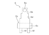
- FIG. 2 is a schematic view of the fixed terminal 6 as viewed from the left.
- the fixed terminal 6 includes a fixed contact 6a, a contact portion 6b, a supported portion 6c, an intermediate portion 6d, and an exposed portion 6e.
- the fixed contact 6a is arranged in the case 2.
- the fixed contact 6a is arranged at the contact portion 6b.
- the fixed contact 6a may be integrated with the fixed terminal 6 or may be a separate body.
- the contact portion 6b supports the fixed contact 6a.
- the contact portion 6b is arranged on one end (upper end) side of the fixed terminal 6.
- the supported portion 6c is supported by the base 2a of the case 2.
- the supported portion 6c is press-fitted and fixed to the base 2a, for example.
- the width of the supported portion 6c is larger than the width of the contact portion 6b.
- the width of the supported portion 6c is equivalent to the width of the lower end portion of the intermediate portion 6d.
- the width of the supported portion 6c may be larger than the width of the intermediate portion 6d.
- the intermediate portion 6d is located between the contact portion 6b and the supported portion 6c.
- the intermediate portion 6d connects the contact portion 6b and the supported portion 6c.
- the intermediate portion 6d is formed so that the cross-sectional area gradually increases from the contact portion 6b toward the supported portion 6c.
- the intermediate portion 6d in the present embodiment is formed so that the cross-sectional area gradually increases in the width direction (front-back direction) of the fixed terminal 6. Further, the intermediate portion 6d is formed so that the cross-sectional area gradually increases toward the base 2a.
- the intermediate portion 6d is formed so that the cross-sectional area continuously increases from the contact portion 6b toward the supported portion 6c. That is, the intermediate portion 6d is formed so as to continuously spread in the width direction from the contact portion 6b toward the supported portion 6c. In the present embodiment, the contact portion 6b is also formed so that the cross-sectional area continuously increases toward the supported portion 6c.
- the exposed portion 6e is exposed to the outside from the base 2a of the case 2.
- the exposed portion 6e projects downward from the base 2a of the case 2.
- the exposed portion 6e includes an external connecting portion 6f and a heat radiating portion 6g.
- the external connection portion 6f is arranged on the other end (lower end) side of the fixed terminal 6.
- the external connection portion 6f is electrically connected to an external device (not shown).
- the cross-sectional area of the external connection portion 6f is smaller than the cross-sectional area of the supported portion 6c. That is, the width of the external connection portion 6f is smaller than the width of the supported portion 6c.
- the cross-sectional area of the external connection portion 6f is smaller than the cross-sectional area of the intermediate portion 6d.
- the width of the external connection portion 6f is smaller than the width of the intermediate portion 6d.
- the cross-sectional area of the supported portion 6c is equivalent to the cross-sectional area of the lower end portion of the intermediate portion 6d, but the cross-sectional area of the supported portion 6c is based on the cross-sectional area of the lower end portion of the intermediate portion 6d. It may be large.
- the heat radiating portion 6g is arranged between the supported portion 6c and the external connecting portion 6f.
- the cross-sectional area of the heat radiating portion 6g is larger than the cross-sectional area of the external connecting portion 6f. That is, the width of the heat radiating portion 6g is larger than the width of the external connecting portion 6f.
- the width of the heat radiating portion 6g is equivalent to the width of the supported portion 6c.
- the width of the heat radiating portion 6g may be larger than the width of the supported portion 6c.
- the heat radiating portion 6g may be arranged in contact with an external substrate, for example.
- the movable contact piece 7 is composed of an elastically deformable leaf spring, and is arranged so as to face the fixed terminal 6. In the present embodiment, the movable contact piece 7 has the same shape as the fixed terminal 6.
- the movable contact piece 7 includes a movable contact 7a, a movable contact 7a, a contact portion 7b, a supported portion 7c, an intermediate portion 7d, and an exposed portion 7e.
- the movable contact 7a is arranged in the case 2.
- the movable contact 7a is arranged at the contact portion 7b.
- the movable contact 7a can come into contact with the fixed contact 6a.
- the movable contact 7a may be integrated with the movable contact piece 7 or may be a separate body.
- the contact portion 7b has the same configuration as the contact portion 6b.
- the supported portion 7c has the same configuration as the supported portion 6c.
- the intermediate portion 7d has the same configuration as the intermediate portion 6d.
- the exposed portion 7e has the same configuration as the exposed portion 6e.
- the exposed portion 7e includes an external connecting portion 7f and a heat radiating portion 7g.
- the movable mechanism 8 includes the card member 10.
- the card member 10 is supported by the base 2a so as to be rotatable in the left-right direction.
- the card member 10 is arranged between the movable contact piece 7 and the drive device 4.
- the card member 10 is connected to the movable contact piece 7 and the drive device 4.
- the movable mechanism 8 moves the movable contact piece 7 in the contact direction Z1 in which the movable contact 7a contacts the fixed contact 6a and the opening direction Z2 in which the movable contact 7a opens.
- the moving direction of the movable contact piece 7 in the present embodiment coincides with the left-right direction.
- the drive device 4 operates the movable mechanism 8 by an electromagnetic force. Specifically, the driving device 4 moves the movable contact piece 7 in the contact direction Z1 and the opening direction Z2 by rotating the card member 10 by an electromagnetic force.
- the drive device 4 is supported by the base 2a.
- the drive device 4 includes a coil 4a, a movable iron piece 4b, a yoke 4c, and an iron core 4d.
- the movable iron piece 4b is supported by the yoke 4c.
- the movable iron piece 4b is attracted to the iron core 4d and rotates, and the movable iron piece 4b presses the card member 10.
- the movable contact piece 7 is pressed in the contact direction Z1.
- the movable contact 7a comes into contact with the fixed contact 6a.
- FIG. 1 shows a state in which a voltage is applied to the coil 4a, that is, a state in which the movable contact 7a is in contact with the fixed contact 6a.
- the intermediate portion 6d of the fixed terminal 6 is formed so that the cross-sectional area gradually increases toward the supported portion 6c.
- the heat transfer path through which the heat of the contact portion 6b is transferred is formed by the intermediate portion 6d, so that the heat generated from the contact portion 6b can be easily released to the outside.
- the intermediate portion 7d of the movable contact piece 7 is formed so that the cross-sectional area gradually increases toward the supported portion 7c.
- the heat transfer path through which the heat of the contact portion 7b is transferred is formed by the intermediate portion 7d, so that the heat generated from the contact portion 7b can be easily released to the outside.
- the heat radiating portions 6g and 7g can more efficiently release the heat generated by the fixed terminal 6 and the movable contact piece 7 to the outside.
- the heat radiating portions 6g and 7g are arranged in contact with the external substrate, the heat generated by the fixed terminal 6 and the movable contact piece 7 can be efficiently dissipated from the substrate.
- the present invention is not limited to the above embodiment, and various modifications can be made without departing from the gist of the invention.
- the configuration of the drive device 4 may be changed.
- the shapes or arrangements of the case 2, the contact device 3, the fixed terminal 6, the movable contact piece 7, and the movable mechanism 8 may be changed.
- At least one of the intermediate portion 6d of the fixed terminal 6 and the intermediate portion 7d of the movable contact piece 7 may be formed so that the cross-sectional area gradually increases toward the supported portion 6c or the supported portion 7c. That is, one of the intermediate portion 6d of the fixed terminal 6 and the intermediate portion 7d of the movable contact piece 7 may have a uniform width. Further, the heat radiating portions 6g and 7g may be omitted. The fixed terminal 6 and the movable contact piece 7 may have a partially bent shape.
- the electromagnetic relay 100 may include a plurality of fixed terminals 6.
- the movable contact piece 7 does not include the exposed portion 7e and is arranged so as to face each fixed terminal 6.
- the fixed terminal 6 may be formed so that the cross-sectional area gradually increases in the thickness direction (left-right direction).
- the fixed terminal 6 may be formed so that the cross-sectional area gradually increases in the thickness direction, for example, by laminating a plurality of plate-shaped members.
- the intermediate portion 6d of the fixed terminal 6 does not have to have a symmetrical shape, and does not have to have a symmetrical shape in the thickness direction. Further, as shown in FIG. 5, the intermediate portion 6d of the fixed terminal 6 may be formed so as to expand stepwise in the width direction from the contact portion 6b toward the supported portion 6c.
- the external connection portion 6f may be bifurcated.
- the cross-sectional area of the external connection portion 6f may be equal to the cross-sectional area of the supported portion 6c or larger than the cross-sectional area of the supported portion 6c.
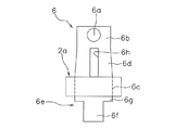
- the intermediate portion 6d of the fixed terminal 6 may further include a slit 6h penetrating in the thickness direction.
- the slit 6h is formed at the center of the fixed terminal 6 in the width direction.
- the contact portion 6b may have a uniform width. The configuration shown in FIGS. 3 to 7 can be applied to the movable contact piece 7.
- the present invention has been applied to a hinge type electromagnetic relay, but the present invention may be applied to a plunger type electromagnetic relay. That is, the present invention may be applied to a plate-shaped or cylindrical fixed terminal 6 used in a plunger type electromagnetic relay.
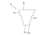
- 8 and 9 show an example in which the present invention is applied to the cylindrical fixed terminal 6.
- FIG. 8 shows a configuration in which the intermediate portion 6d of the fixed terminal 6 continuously increases in cross-sectional area from the contact portion 6b toward the supported portion 6c.
- FIG. 9 shows a configuration in which the intermediate portion 6d of the fixed terminal 6 extends stepwise in the width direction from the contact portion 6b toward the supported portion 6c.
- the configuration corresponding to the embodiment is designated by the same reference numerals as those in the embodiment.
Landscapes
- Physics & Mathematics (AREA)
- Electromagnetism (AREA)
- Contacts (AREA)
Abstract
電磁継電器は、ケースと、固定端子と、可動接触片と、可動機構と、駆動装置と、を備える。固定端子は、ケース内に配置される固定接点を含む。可動接触片は、固定接点に接触可能な可動接点を含む。可動機構は、可動接触片を移動させる。駆動装置は、電磁力によって可動機構を作動させる。固定端子及び可動接触片の少なくも一方は、接点部と、被支持部と、中間部とを含む。接点部は、固定接点又は可動接点が配置される。被支持部は、ケースに支持される。中間部は、接点部と被支持部とを接続する。中間部は、接点部から被支持部に向かって断面積が徐々に大きくなるように形成されている。
Description
本発明は、電磁継電器に関する。
従来、電気回路を開閉する電磁継電器が知られている。電磁継電器は、ケースと、
接点装置と、接点装置を駆動する駆動装置と、を備えている。接点装置は、固定端子と、可動接触片とを含み、ケースに収容されている(特許文献1参照)。
接点装置と、接点装置を駆動する駆動装置と、を備えている。接点装置は、固定端子と、可動接触片とを含み、ケースに収容されている(特許文献1参照)。
電磁継電器では、固定端子や可動接触片の発熱によって通電容量が低下するので、通電時における固定端子や可動接触片の発熱を効率よく外部に逃がすことが好ましい。
本発明の課題は、電磁継電器において、固定端子や可動接触片の発熱を外部に逃がし易くすることにある。
本発明の一態様に係る電磁継電器は、ケースと、固定端子と、可動接触片と、可動機構と、駆動装置と、を備える。固定端子は、ケース内に配置される固定接点を含む。可動接触片は、固定接点に接触可能な可動接点を含む。可動機構は、可動接触片を移動させる。駆動装置は、電磁力によって可動機構を作動させる。固定端子及び可動接触片の少なくも一方は、接点部と、被支持部と、中間部とを含む。接点部は、固定接点又は可動接点が配置される。被支持部は、ケースに支持される。中間部は、接点部と被支持部とを接続する。中間部は、接点部から被支持部に向かって断面積が徐々に大きくなるように形成されている。
この電磁継電器では、固定端子及び可動接触片の少なくとも一方に、接点部から被支持部に向かって断面積が徐々に大きくなるように形成される中間部が設けられる。すなわち、中間部によって接点部の熱が伝わる伝熱経路が形成されるので、接点部からの発熱を外部に逃がし易くすることができる。その結果、固定端子や可動接触片の発熱を効率よく外部に逃がすことができる。
中間部は、固定端子又は可動接触片の幅方向において断面積が徐々に大きくなるように形成されてもよい。この場合においても、中間部によって接点部の熱が伝わる伝熱経路が形成されるので、接点部からの発熱を外部に逃がし易くすることができる。
中間部は、固定端子又は可動接触片の厚み方向において断面積が徐々に大きくなるように形成されてもよい。この場合においても、中間部によって接点部の熱が伝わる伝熱経路が形成されるので、接点部からの発熱を外部に逃がし易くすることができる。
固定端子及び可動接触片の少なくとも一方は、複数の板状部材を積層して構成されてもよい。この場合は、厚み方向における中間部の断面積を簡単な構成で徐々に大きくすることができる。
中間部は、接点部から被支持部に向かって断面積が連続的に大きくなるように形成されている。この場合は、伝熱経路を形成し易くなる。
固定端子及び可動接触片の少なくとも一方は、被支持部に接続されケースから外部に露出する露出部をさらに含んでもよい。露出部は、断面積が被支持部の断面積よりも小さい外部接続部を含んでもよい。この場合は、外部接続部と外部機器との接続が容易になる。
露出部は、被支持部と外部接続部の間に配置され断面積が外部接続部の断面積よりも大きい放熱部をさらに含んでもよい。この場合は、放熱部によって固定端子や可動接触片の発熱をさらに効率よく外部に逃がすことができる。
中間部は、固定端子又は可動接触片の厚み方向に貫通するスリット部を含んでもよい。この場合においても、中間部によって接点部の熱が伝わる伝熱経路が形成されるので、接点部からの発熱を外部に逃がし易くすることができる。
本発明によれば、電磁継電器において、固定端子や可動接触片の発熱を外部に逃がし易くすることができる。
以下、本発明の一態様に係る電磁継電器の実施形態について、図面を参照して説明する。図面を参照するときにおいて、説明を分かり易くするために図1における上側を「上」、下側を「下」、左側を「左」、右側を「右」、紙面の手前側を「前」、紙面の奥側を「後」として説明する。図1は電磁継電器100の内部を前方から見た模式図である。
電磁継電器100は、いわゆるヒンジ型の電磁継電器である。電磁継電器100は、ケース2と、接点装置3と、駆動装置4とを備えている。ケース2は、樹脂などの絶縁性を有する材料で形成されている。ケース2は、ベース2aと、カバー2bとを含む。
ベース2aは、接点装置3と駆動装置4とを支持する。カバー2bは、下方に向けて開口する箱型の部材であり、ベース2aを上方から覆うようにベース2aに固定されている。
接点装置3は、ベース2aに支持されている。接点装置3は、ケース2に収容されている。接点装置3は、固定端子6と、可動接触片7と、可動機構8と、を含む。固定端子6及び可動接触片7は、厚みが均一の板状の端子であり、導電性を有する材料で形成されている。固定端子6及び可動接触片7は、上下方向に延びており、ベース2aに圧入固定されている。
図2は、固定端子6を左方から見た模式図である。固定端子6は、固定接点6aと、接点部6bと、被支持部6cと、中間部6dと、露出部6eとを含む。固定接点6aは、ケース2内に配置されている。固定接点6aは、接点部6bに配置されている。固定接点6aは、固定端子6と一体であってもよいし、別体であってもよい。
接点部6bは、固定接点6aを支持する。接点部6bは、固定端子6の一端(上端)側に配置されている。被支持部6cは、ケース2のベース2aに支持されている。被支持部6cは、ベース2aに例えば圧入固定されている。被支持部6cの幅は、接点部6bの幅よりも大きい。被支持部6cの幅は、中間部6dの下端部の幅と同等である。なお、被支持部6cの幅は、中間部6dの幅より大きくてもよい。
中間部6dは、接点部6bと被支持部6cの間に位置している。中間部6dは、接点部6bと被支持部6cとを接続する。中間部6dは、接点部6bから被支持部6cに向かって断面積が徐々に大きくなるように形成されている。本実施形態における中間部6dは、固定端子6の幅方向(前後方向)において断面積が徐々に大きくなるように形成されている。また、中間部6dは、ベース2aに向かって断面積が徐々に大きくなるように形成されている。
中間部6dは、接点部6bから被支持部6cに向かって断面積が連続的に大きくなるように形成されている。すなわち、中間部6dは、接点部6bから被支持部6cに向かって幅方向に連続的に広がるように形成されている。なお、本実施形態では、接点部6bにおいても、被支持部6cに向かって断面積が連続的に大きくなるように形成されている。
露出部6eは、ケース2のベース2aから外部に露出する。露出部6eは、ケース2のベース2aから下方に突出している。露出部6eは、外部接続部6fと、放熱部6gとを含む。外部接続部6fは、固定端子6の他端(下端)側に配置されている。外部接続部6fは、図示しない外部機器と電気的に接続される。外部接続部6fの断面積は、被支持部6cの断面積よりも小さい。すなわち、外部接続部6fの幅は、被支持部6cの幅よりも小さい。外部接続部6fの断面積は、中間部6dの断面積よりも小さい。すなわち、外部接続部6fの幅は、中間部6dの幅よりも小さい。なお、本実施形態では、被支持部6cの断面積は、中間部6dの下端部の断面積と同等であるが、被支持部6cの断面積は、中間部6dの下端部の断面積より大きくてもよい。
放熱部6gは、被支持部6cと外部接続部6fの間に配置されている。放熱部6gの断面積は、外部接続部6fの断面積よりも大きい。すなわち、放熱部6gの幅は、外部接続部6fの幅よりも大きい。放熱部6gの幅は、被支持部6cの幅と同等である。なお、放熱部6gの幅は、被支持部6cの幅よりも大きくてもよい。放熱部6gは、例えば、外部の基板に接触して配置されてもよい。
可動接触片7は、弾性変形可能な板ばねで構成されており、固定端子6に対向して配置されている。本実施形態では、可動接触片7は、固定端子6と同様の形状を有している。可動接触片7は、可動接点7aと、可動接点7aと、接点部7bと、被支持部7cと、中間部7dと、露出部7eとを含む。可動接点7aは、ケース2内に配置されている。可動接点7aは、接点部7bに配置されている。可動接点7aは、固定接点6aに接触可能である。可動接点7aは、可動接触片7と一体であってもよいし、別体であってもよい。
接点部7bは、接点部6bと同様の構成である。被支持部7cは、被支持部6cと同様の構成である。中間部7dは、中間部6dと同様の構成である。露出部7eは、露出部6eと同様の構成である。露出部7eは、外部接続部7fと、放熱部7gとを含む。
可動機構8は、カード部材10を含む。カード部材10は、左右方向に回動可能にベース2aに支持されている。カード部材10は、可動接触片7と駆動装置4との間に配置されている。カード部材10は、可動接触片7と駆動装置4に接続されている。可動機構8は、可動接点7aが固定接点6aに接触する接触方向Z1と開離する開離方向Z2とに可動接触片7を移動させる。本実施形態における可動接触片7の移動方向は、左右方向と一致する。
駆動装置4は、電磁力によって可動機構8を作動させる。詳細には、駆動装置4は、電磁力によってカード部材10を回動させることによって、可動接触片7を接触方向Z1及び開離方向Z2に移動させる。
駆動装置4は、ベース2aに支持されている。駆動装置4は、コイル4aと、可動鉄片4b、ヨーク4cと、鉄心4dとを含む。可動鉄片4bは、ヨーク4cに支持されている。コイル4aに電圧が印加されて励磁されると、可動鉄片4bが鉄心4dに吸引されて回動し、可動鉄片4bがカード部材10を押圧する。カード部材10が可動鉄片4bに押圧されることで、可動接触片7が接触方向Z1に押圧される。これにより、可動接点7aが固定接点6aに接触する。なお、図1では、コイル4aに電圧が印加された状態、すなわち可動接点7aが固定接点6aに接触した状態を示している。
上述した電磁継電器100では、固定端子6の中間部6dが被支持部6cに向かって断面積が徐々に大きくなるように形成されている。これにより、接点部6bの熱が伝わる伝熱経路が中間部6dによって形成されるので、接点部6bからの発熱を外部に逃がし易くすることができる。同様に、可動接触片7の中間部7dが被支持部7cに向かって断面積が徐々に大きくなるように形成されている。これにより、接点部7bの熱が伝わる伝熱経路が中間部7dによって形成されるので、接点部7bからの発熱を外部に逃がし易くすることができる。
また、放熱部6g,7gによって、固定端子6や可動接触片7の発熱をさらに効率よく外部に逃がすことができる。例えば、放熱部6g,7gを外部の基板に接触して配置した場合は、固定端子6や可動接触片7の発熱を基盤に効率よく逃がすことも可能になる。
以上、本発明の一態様に係る電磁継電器の実施形態について説明したが、本発明は上記実施形態に限定されるものではなく、発明の要旨を逸脱しない範囲で種々の変更が可能である。例えば、駆動装置4の構成が変更されてもよい。また、ケース2、接点装置3、固定端子6、可動接触片7及び可動機構8の形状、或いは配置が変更されてもよい。
固定端子6の中間部6d及び可動接触片7の中間部7dの少なくとも一方が被支持部6c又は被支持部7cに向かって断面積が徐々に大きくなるように形成されていればよい。すなわち、固定端子6の中間部6d及び可動接触片7の中間部7dの一方は、幅が均一であってもよい。また、放熱部6g,7gは省略されてもよい。固定端子6及び可動接触片7は、一部が屈曲した形状を有してもよい。
電磁継電器100は、固定端子6を複数備えていてもよい。この場合、可動接触片7は、露出部7eは含まず、各固定端子6に対向して配置される。
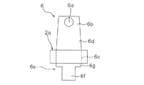
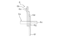
図3に示すように、固定端子6は、厚み方向(左右方向)において断面積が徐々に大きくなるように形成されてもよい。この場合、固定端子6は、例えば、複数の板状部材を積層して構成することで、厚み方向において断面積が徐々に大きくなるように形成されてもよい。
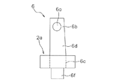
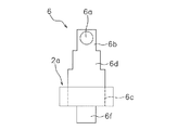
図4に示すように、固定端子6の中間部6dは、左右対称な形状でなくてもよいし、厚み方向に対称な形状でなくてもよい。また、図5に示すように、固定端子6の中間部6dは、接点部6bから被支持部6cに向かって幅方向に階段状に拡がるように形成してもよい。
図6に示すように、外部接続部6fは、2股に分岐していてもよい。なお、外部接続部6fの断面積は、被支持部6cの断面積と同等或いは被支持部6cの断面積より大きくてもよい。
図7に示すように、固定端子6の中間部6dは、厚み方向に貫通するスリット6hをさらに含んでもよい。スリット6hは、固定端子6の幅方向における中央に形成されている。また、図7に示すように、接点部6bは、幅が均一であってもよい。なお、図3から図7に示す構成は、可動接触片7に適用することが可能である。
前記実施形態では、ヒンジ型の電磁継電器に本発明を適用していたが、プランジャ型の電磁継電器に本発明を適用してもよい。すなわち、プランジャ型の電磁継電器に用いられる板状又は円柱形状の固定端子6に本発明を適用してもよい。図8及び図9では、円柱形状の固定端子6に本発明を適用した実施例を示している。図8では、固定端子6の中間部6dが接点部6bから被支持部6cに向かって断面積が連続的に大きくなる構成を示している。図9では、固定端子6の中間部6dが接点部6bから被支持部6cに向かって幅方向に階段状に拡がる構成を示している。なお、図8及び図9において、前記実施形態に対応する構成は、前記実施形態と同じ符号を付している。
本発明によれば、電磁継電器において、固定端子や可動接触片の発熱を外部に逃がし易くすることができる。
2 ケース
4 駆動装置
6 固定端子
6a 固定接点
6b,7b 接点部
6c,7c 被支持部
6d,7c 中間部
6e,7e 露出部
6f,7f 外部接続部
6g,7g 放熱部
6h スリット部
7 可動接触片
7a 可動接点
8 可動機構
100 電磁継電器
4 駆動装置
6 固定端子
6a 固定接点
6b,7b 接点部
6c,7c 被支持部
6d,7c 中間部
6e,7e 露出部
6f,7f 外部接続部
6g,7g 放熱部
6h スリット部
7 可動接触片
7a 可動接点
8 可動機構
100 電磁継電器
Claims (8)
- ケースと、
前記ケース内に配置される固定接点を含む固定端子と、
前記固定接点に接触可能な可動接点を含む可動接触片と、
前記可動接触片を移動させる可動機構と、
電磁力によって前記可動機構を作動させる駆動装置と、
を備え、
前記固定端子及び前記可動接触片の少なくとも一方は、
前記固定接点又は前記可動接点が配置される接点部と、
前記ケースに支持される被支持部と、
前記接点部から前記被支持部に向かって断面積が徐々に大きくなるように形成され前記接点部と前記被支持部とを接続する中間部と、を含む、
電磁継電器。 - 前記中間部は、前記固定端子又は前記可動接触片の幅方向において断面積が徐々に大きくなるように形成されている、
請求項1に記載の電磁継電器。 - 前記中間部は、前記固定端子又は前記可動接触片の厚み方向において断面積が徐々に大きくなるように形成されている、
請求項1又は2に記載の電磁継電器。 - 前記固定端子及び前記可動接触片の少なくとも一方は、複数の板状部材を積層して構成されている、
請求項3に記載の電磁継電器。 - 前記中間部は、前記接点部から前記被支持部に向かって断面積が連続的に大きくなるように形成されている、
請求項1から4のいずれか1項に記載の電磁継電器。 - 前記固定端子及び前記可動接触片の少なくとも一方は、前記被支持部に接続され前記ケースから外部に露出する露出部をさらに含み、
前記露出部は、断面積が前記被支持部の断面積よりも小さい外部接続部を含む、
請求項1から5のいずれか1項に記載の電磁継電器。 - 前記露出部は、前記被支持部と前記外部接続部の間に配置され断面積が前記外部接続部の断面積よりも大きい放熱部をさらに含む、
請求項6に記載の電磁継電器。 - 前記中間部は、前記固定端子又は前記可動接触片の厚み方向に貫通するスリット部を含む、
請求項1から7のいずれか1項に記載の電磁継電器。
Applications Claiming Priority (2)
| Application Number | Priority Date | Filing Date | Title |
|---|---|---|---|
| JP2020-051594 | 2020-03-23 | ||
| JP2020051594A JP2021150253A (ja) | 2020-03-23 | 2020-03-23 | 電磁継電器 |
Publications (1)
| Publication Number | Publication Date |
|---|---|
| WO2021192535A1 true WO2021192535A1 (ja) | 2021-09-30 |
Family
ID=77849395
Family Applications (1)
| Application Number | Title | Priority Date | Filing Date |
|---|---|---|---|
| PCT/JP2021/001407 Ceased WO2021192535A1 (ja) | 2020-03-23 | 2021-01-18 | 電磁継電器 |
Country Status (2)
| Country | Link |
|---|---|
| JP (1) | JP2021150253A (ja) |
| WO (1) | WO2021192535A1 (ja) |
Citations (4)
| Publication number | Priority date | Publication date | Assignee | Title |
|---|---|---|---|---|
| JPS55149237U (ja) * | 1979-04-15 | 1980-10-27 | ||
| JPS5650U (ja) * | 1979-06-15 | 1981-01-06 | ||
| JPH10326553A (ja) * | 1997-05-28 | 1998-12-08 | Matsushita Electric Works Ltd | 電磁リレー |
| JP2016177961A (ja) * | 2015-03-19 | 2016-10-06 | オムロン株式会社 | リレー |
-
2020
- 2020-03-23 JP JP2020051594A patent/JP2021150253A/ja active Pending
-
2021
- 2021-01-18 WO PCT/JP2021/001407 patent/WO2021192535A1/ja not_active Ceased
Patent Citations (4)
| Publication number | Priority date | Publication date | Assignee | Title |
|---|---|---|---|---|
| JPS55149237U (ja) * | 1979-04-15 | 1980-10-27 | ||
| JPS5650U (ja) * | 1979-06-15 | 1981-01-06 | ||
| JPH10326553A (ja) * | 1997-05-28 | 1998-12-08 | Matsushita Electric Works Ltd | 電磁リレー |
| JP2016177961A (ja) * | 2015-03-19 | 2016-10-06 | オムロン株式会社 | リレー |
Also Published As
| Publication number | Publication date |
|---|---|
| JP2021150253A (ja) | 2021-09-27 |
Similar Documents
| Publication | Publication Date | Title |
|---|---|---|
| JP5864960B2 (ja) | 電磁継電器 | |
| CN102024625B (zh) | 电磁继电器 | |
| CN108022799B (zh) | 电磁继电器 | |
| CN102222588B (zh) | 电磁继电器 | |
| JP6981732B2 (ja) | 電磁継電器 | |
| US10636603B2 (en) | Electromagnetic relay | |
| JP2004172036A (ja) | 電磁リレー | |
| CN107924789B (zh) | 继电器 | |
| CN112582218B (zh) | 继电器 | |
| JP2010108653A (ja) | 電磁継電器 | |
| CN112530745A (zh) | 电磁继电器 | |
| US10658141B2 (en) | Electromagnetic relay | |
| JP7327027B2 (ja) | 電磁継電器 | |
| CN107408477A (zh) | 继电器 | |
| CN110520957A (zh) | 触点装置和电磁继电器 | |
| JP2021150253A (ja) | 電磁継電器 | |
| JP7652538B2 (ja) | 電磁継電器 | |
| JP7452113B2 (ja) | 電磁継電器 | |
| JP7505213B2 (ja) | 電磁継電器 | |
| JP7443913B2 (ja) | 電磁継電器 | |
| JP7501328B2 (ja) | 電磁継電器 | |
| JP2016201289A (ja) | 接点装置およびそれを用いた開閉器システム | |
| JP2604534B2 (ja) | 電磁継電器 | |
| JP7420056B2 (ja) | 電磁継電器 | |
| CN112889126B (zh) | 触点装置 |
Legal Events
| Date | Code | Title | Description |
|---|---|---|---|
| 121 | Ep: the epo has been informed by wipo that ep was designated in this application |
Ref document number: 21774395 Country of ref document: EP Kind code of ref document: A1 |
|
| NENP | Non-entry into the national phase |
Ref country code: DE |
|
| 122 | Ep: pct application non-entry in european phase |
Ref document number: 21774395 Country of ref document: EP Kind code of ref document: A1 |