WO2021192386A1 - 掘削装置並びに掘削方法 - Google Patents
掘削装置並びに掘削方法 Download PDFInfo
- Publication number
- WO2021192386A1 WO2021192386A1 PCT/JP2020/040497 JP2020040497W WO2021192386A1 WO 2021192386 A1 WO2021192386 A1 WO 2021192386A1 JP 2020040497 W JP2020040497 W JP 2020040497W WO 2021192386 A1 WO2021192386 A1 WO 2021192386A1
- Authority
- WO
- WIPO (PCT)
- Prior art keywords
- excavation
- excavated
- casing
- rod
- hole
- Prior art date
- Legal status (The legal status is an assumption and is not a legal conclusion. Google has not performed a legal analysis and makes no representation as to the accuracy of the status listed.)
- Ceased
Links
Images



Classifications
-
- E—FIXED CONSTRUCTIONS
- E21—EARTH OR ROCK DRILLING; MINING
- E21B—EARTH OR ROCK DRILLING; OBTAINING OIL, GAS, WATER, SOLUBLE OR MELTABLE MATERIALS OR A SLURRY OF MINERALS FROM WELLS
- E21B17/00—Drilling rods or pipes; Flexible drill strings; Kellies; Drill collars; Sucker rods; Cables; Casings; Tubings
- E21B17/22—Rods or pipes with helical structure
Definitions
- the present invention relates to an excavation device and an excavation method.
- the excavation conditions, etc. it is not possible to consolidate all the earth and sand into the hole wall, and the earth and sand may be discharged to the ground.
- the excavated earth and sand may contain industrial waste and harmful substances such as fluorine due to natural factors.
- an object of the present invention is to provide an excavation device and an excavation method capable of preventing the spread of environmental pollution at an excavation site even when the soil contains harmful substances such as industrial waste and fluorine. ..
- the excavation device is provided at one end of a rod, an excavation portion for excavating the ground, a casing surrounding at least a part of the rod, and the excavation portion provided on the excavation portion side of the casing. It is provided with an intrusion prevention unit for preventing the excavated material excavated by the vehicle from entering the casing.
- the excavating device includes an excavating portion provided at one end of a rod for excavating the ground, a casing surrounding at least a part of the rod, and a changing portion for changing the size of the outer shape of the excavating portion. It is provided with a supply unit for supplying treated soil to the excavated hole excavated by the excavation unit.
- the excavating device includes an excavating portion provided at one end of a rod for excavating the ground, a casing surrounding at least a part of the rod, and a moving portion for moving the casing relative to the rod. , Is equipped.
- the excavation method according to claim 12 includes a step of surrounding an excavation portion for excavating the ground with a casing that surrounds at least a part of the rod, and a state in which the casing surrounds the excavation portion. It includes a step of supplying treated soil to the excavated hole excavated by the excavation part.
- the intrusion prevention unit prevents the excavated material from entering the casing, it is possible to reduce the intrusion of the excavated material into the casing, and by extension, the excavated material is discharged to the ground surface. Can be reduced.
- the excavated hole can be replaced with the treated soil.
- the moving portion can move the casing relative to the rod.
- the excavation hole can be replaced with treated soil by utilizing the casing.
- the excavator 1 of the present embodiment is attached to a leader of a three-point pile driver (not shown) and suspended by a wire.
- the excavation device 1 excavates by the weight of the excavation device 1 and the rotation of the excavation section 10 described later.
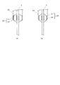
- FIG. 1 is a diagram showing an outline of the excavation device 1 of the present embodiment, (a) a diagram showing a case where the excavation portion 10 is outside the casing 30, and (b) a case where the excavation portion 10 is inside the casing 30. It is a figure which shows the state which (c) a part of excavation part was replaced with fluidized soil.
- FIG. 2 is a block diagram of the excavator 1 of the present embodiment. Hereinafter, the description of the excavator 1 will be continued with reference to FIGS. 1 and 2.
- the drawings used in the present embodiment are not necessarily the same in scale as the actual ones in order to facilitate understanding and avoid complication of the drawings, and the illustration of each component is also simplified. ..
- the excavation device 1 includes a rod 3 connected to the drive device 2, an excavation section 10 provided at the tip of the rod 3, and an intrusion prevention section 20 provided on the rod 3 in the vicinity of the excavation section 10.
- a casing 30 capable of surrounding (accommodating) the excavated portion 10 and the intrusion prevention portion 20, a moving device 35 for moving the casing 30 in the Z direction in the drawing, and a supply of treated soil to the excavated hole excavated by the excavated portion 10. It has a unit 40 and a control device 50 that controls the entire excavation device 1.
- the casing 30 partially surrounds the rod 3 and is divided into a first casing portion 31 and a second casing portion 32 capable of accommodating the excavation portion 10 and the intrusion prevention portion 20. It is separated.
- the drive device 2 has a motor, a speed reducer, and the like, and rotates the rod 3 in the forward or reverse direction around the Z axis.
- the rod 3 is a metal member having a hollow portion 3a (see FIG. 3), one end side of which is connected to the drive device 2, and the other end side of which is provided with an excavation portion 10. Further, the rod 3 is provided with an intrusion prevention unit 20. Therefore, the rod 3, the excavation portion 10, the intrusion prevention portion 20, and the casing 30 are integrally moved in the Z-axis direction by the driving force from the driving device 2.
- the rod 3 moves downward ( ⁇ Z direction) due to the weight of the excavator 1 during normal rotation, and moves upward (+ Z direction) due to the wire during reverse rotation.
- the hollow portion 3a of the rod 3 is used for arranging hydraulic or pneumatic piping, or for supplying treated soil 43, which will be described later, to a hole formed by excavation.
- a swivel may be provided in the piping so that the hydraulic or pneumatic piping is not affected by the rotation of the rod 3.
- the excavation portion 10 is formed in the rod 3, and an excavation hole having a predetermined depth (for example, 10 m to 20 m) is formed in the ground by the normal rotation of the rod 3.
- the excavation portion 10 has an excavation blade 11 provided at the other end of the rod 3, a screw 12, and a trowell 13.
- the excavation blade 11 has a plurality of metal blades and excavates the ground.
- the screw 12 transfers the excavated material upward by a lifting action as the rod 3 rotates in the normal direction.
- the outer shape of the screw 12 is smaller than the inner diameter of the second casing portion 32.
- the trowell 13 projects outward from the peripheral surface of the rod 3 to the outer edge position of the screw 12, and pushes the excavated material transferred upward by the screw 12 to the outside and consolidates it into the hole wall.
- the screw 12 and the trowell 13 are provided on the other end side of the rod 3, for example, about 1 m to 3 m, but they may be provided on the entire rod 3 except for the vicinity of the tip of the rod 3.
- a screw 12 and a trowell 13 may be provided.
- the trowell 13 is provided at a position where the screw 12 is turned by one pitch, but may be provided at a place where the screw 12 is turned by 1.5 to 2 pitches.
- FIG. 3 is a cross-sectional view of a portion AA of the excavation device 1 of FIG. 1 (b).
- the reduction (diameter reduction) mechanism of the trowell 13 and the reduction (diameter reduction) mechanism of the excavation blade 11 will be described with reference to FIG.
- the trowell 13 is rotatably engaged by a pin 25 formed on the surface side (+ Z side) of the screw 12.
- the drive device 2 rotates the rod 3 in the forward direction (clockwise)
- the trowell 13 projects outward from the outer shape of the second casing portion 32 due to this rotational force, and the stopper 26a is used at the position indicated by the dotted line.
- the above-mentioned consolidation is performed at the location indicated by reference numeral 29 in a state where the trowell 13 projects outward from the outer shape of the second casing portion 32.
- the trowell 13 is positioned inside the outer shape of the second casing portion 32 due to this rotational force, as shown by the solid line. Is positioned by the stopper 26b. As a result, as shown in FIGS. 1 (b) and 1 (c), the second casing portion 32 can surround the trowell 13.
- the stoppers 26a and 26b are fixed to the surface side of the screw 12.
- the excavation blade 11 is rotatably engaged by a pin 27 formed on the back surface side ( ⁇ Z side) of the screw 12.
- the driving device 2 rotates the rod 3 in the forward direction (clockwise)
- the excavating blade 11 projects outward from the outer shape of the second casing portion 32 due to this rotational force, and a part thereof is shown by a solid line. It is positioned by the stopper 28a at the position where it is.
- the excavation blade 11 is outside the second casing portion 32, excavation using the excavation blade 11 is performed.
- the excavation hole diameter excavated by the excavation blade 11 is smaller than the consolidation diameter at which the trowell 13 compacts the excavation hole, but the excavation hole diameter excavated by the excavation blade 11 is made the same as the consolidation diameter. You may.
- the driving device 2 rotates the rod 3 in the reverse direction (counterclockwise)
- the excavating blade 11 is positioned inside the outer shape of the second casing portion 32 due to this rotational force, as shown by the dotted line. Is positioned by the stopper 28b.
- the second casing portion 32 can accommodate the excavation blade 11.
- the stoppers 28a and 28b are fixedly attached to the back surface side of the screw 12.
- the trowell 13 compacts the excavated material transferred upward by the screw 12 into the hole wall.
- the trowell 13 cannot consolidate all the excavated material into the hole wall due to the condition of the hole wall or the like. For this reason, excavated material that cannot be consolidated in the hole wall unless the intrusion prevention unit 20 is provided is discharged to the ground surface as construction-generated soil (hereinafter referred to as residual soil).
- the intrusion prevention unit 20 is provided inside the other end (-Z side) of the casing 30 in order to prevent residual soil from entering the casing 30. Since the intrusion prevention unit 20 prevents the residual soil from entering the casing 30, the residual soil does not discharge to the ground surface. In particular, when there is a contaminated layer such as waste or fluorine in the ground, the intrusion prevention unit 20 reduces the discharge of the residual soil of the contaminated layer to the ground surface, so that the environment at the excavation site should be kept good. Can be done.
- FIG. 4 is a cross-sectional view showing the details of the intrusion prevention unit 20
- FIG. 4 (a) is a cross-sectional view showing how the intrusion prevention unit is enlarged
- FIG. It is sectional drawing which shows the state of this.
- the reduction (diameter reduction) of the intrusion prevention unit 20 will be described with reference to FIG.
- the intrusion prevention unit 20 has an expansion / contraction portion 21 that expands / contracts by air, hydraulic pressure, or the like, and a flange portion 22 that holds the expansion / contraction portion 21.
- the expansion / contraction portion 21 expands / contracts by hydraulic pressure or pneumatic pressure from the hollow portion 3a of the rod 3.
- the expansion / contraction portion 21 is formed of a resin such as rubber.
- the flange portion 22 has a pair of metal flanges, one flange is fixed to the rod 3 and the other flange faces the second casing portion 32.
- the other flange functions as a protective member that prevents the second casing portion 32 from damaging the expansion / contraction portion 21 when the expansion / contraction portion 21 expands.
- the intrusion prevention portion 20 is housed in the casing 30 except for the tip portion on the excavation portion 10 side ( ⁇ Z side), and the other flange is accommodated during excavation by the excavation portion 10, that is, with the forward rotation of the rod 3.
- the expansion / contraction portion 21 expands until it comes into contact with the second casing portion 32.
- the intrusion prevention unit 20 can prevent the residual soil from invading the casing 30.
- the intrusion prevention portion 20 is reduced so that the other flange is separated from the second casing portion 32 when the excavation portion 10 is housed in the second casing portion 32, that is, with the reverse rotation of the rod 3.
- the excavation portion 10 can be accommodated in the second casing portion 32 by reducing the intrusion prevention portion 20 and moving the second casing portion 32 in the ⁇ Z direction, which will be described later.
- the intrusion prevention unit 20 may be expanded or contracted by a mechanical expansion / contraction mechanism.
- an umbrella opening / closing mechanism may be adopted as the intrusion prevention unit 20 expansion / contraction mechanism.
- the opening / closing mechanism may be opened by the forward rotation of the rod 3, and the opening / closing mechanism may be closed by the reverse rotation of the rod 3.
- the casing 30 is a hollow member made of metal, and has a first casing portion 31 and a second casing portion 32.
- the casing 30 prevents the residual soil from being discharged to the ground surface, and by providing the above-mentioned intrusion prevention unit 20, it is possible to prevent the residual soil from being discharged to the ground surface. Further, the casing 30 prevents the treated soil 43 from coming into contact with the hole wall of the excavation hole when the treated soil 43 is supplied. As a result, the treated soil 43 is not mixed with the residual soil of the hole wall (for example, the residual soil of the contaminated layer).
- the first casing portion 31 is supported by the first flange portion 33 fixed to the rod 3 and surrounds the rod 3 on the drive device 2 side (+ Z side).
- the second casing portion 32 is supported by a second flange portion 34 fixed to the moving device 35 so that the rod 3 can move in the Z direction.
- the second casing portion 32 surrounds the rod 3 on the excavation portion 10 side ( ⁇ Z side).
- the first casing portion 31 and the second casing portion 32 have the same diameter and the lengths are changed, but the present invention is not limited to this. Further, when the first casing portion 31 and the second casing portion 32 rotate due to the rotation of the rod 3, the first casing portion 31 and the second casing portion 32 are not twisted.
- An anti-twist mechanism may be provided to mechanically connect the 31 and the second casing portion 32.
- the moving device 35 is a hydraulic jack in the present embodiment, has a main body portion 36 and a cylinder rod 37, and uses the hydraulic pressure of the hydraulic unit 38 (see FIG. 2) to attach the second casing portion 32 to the rod 3. It moves a predetermined stroke to the ⁇ Z side.
- the moving device 35 moves the second casing portion 32 to the ⁇ Z side according to the dimension of the excavation portion 10 in the Z direction (for example, about 1 m to 3 m) (see FIG. 1 (b)). This is to surround the reduced diameter excavation portion 10 in the second casing portion 32 (see FIGS. 1B and 1C). In this way, the moving device 35 positions the second casing portion 32 at the initial position where the cylinder rod 37 is housed in the main body portion 36 and the surrounding position where the excavation portion 10 is surrounded by the second casing portion 32. ..
- the excavation part 10 After the excavation is completed, if the excavation part 10 is put out to the ground while the excavation part 10 is not housed in the casing 30, there is a risk that the residual soil of the contaminated layer adhering to the excavation part 10 will be discharged to the ground surface. On the other hand, if the excavation portion 10 is housed in the casing 30, it is possible to reduce the possibility that the residual soil of the contaminated layer is discharged to the ground surface. Therefore, according to the present embodiment, the environment at the excavation site can be kept good.
- the supply unit 40 has a valve 41, a pump 42, and a treated soil 43, and supplies the treated soil 43 to the excavated hole excavated by the excavation unit 10.
- the valve 41 is connected to the rod 3 and is normally closed including during excavation, and is switched to the open state when the treated soil 43 is supplied to the excavation hole.
- the pump 42 supplies the treated soil 43 stored in a container (not shown) to the hollow portion of the rod 3 via the valve 41.
- the treated soil 43 fluidized treated soil is used in this embodiment.
- the fluidized soil is, for example, a mixture of locally generated soil of uncontaminated soil with water, cement, etc., and has good fluidity, low water permeability after curing, and high strength, so that it is contaminated with heavy metals, etc. It can prevent the penetration of substances. Further, since the solidification strength can be adjusted by adjusting the addition amount of the solidifying material such as fluidized soil cement, it is possible to reconstruct after the construction.
- the treated soil 43 is not limited to the fluidized treated soil, and alternative products such as uncontaminated soil and uncontaminated sand can be appropriately used in consideration of safety and N value. ..
- the control device 50 has a CPU, a memory, and the like, and controls the excavation device 1.
- the control by the control device 50 of the excavation device 1 of the present embodiment configured as described above will be described with reference to the flowchart of FIG.
- the flowchart of FIG. 5 is started with the moving device 35 in the initial position.
- the control device 50 controls the drive device 2 to rotate the rod 3 in the normal direction. Due to the normal rotation of the rod 3, the excavation blade 11 and the trowell 13 project outward from the outer shape of the second casing portion 32. Further, the control device 50 controls the hydraulic system according to the normal rotation of the rod 3 to enlarge the expansion / contraction unit 21 of the intrusion prevention unit 20.
- the excavation process by the excavation section 10 is started by the own weight of the excavation device 1 and the normal rotation of the rod 3 (step S1).
- the control device 50 determines whether or not the excavation by the excavation unit 10 has been performed to a predetermined depth (step S2).
- the control device 50 repeats the determination in step S2 until the excavation to the predetermined depth is performed, and proceeds to step S3 when the excavation to the predetermined depth is performed.
- the ground is a contaminated layer, an impermeable layer such as cohesive soil, and a non-contaminated layer.
- each layer is set to 5 m, and an excavation depth of 15 m is set to a predetermined depth. ..
- step S2 When the determination in step S2 is Yes, the control device 50 controls the drive device 2 to rotate the rod 3 in the reverse direction. Due to the reverse rotation of the rod 3, the excavation blade 11 and the trowell 13 are positioned inward from the outer shape of the second casing portion 32. As a result, the second casing portion 32 can surround the excavation portion 10. Further, the control device 50 controls the hydraulic system according to the reverse rotation of the rod 3 to reduce the expansion / contraction unit 21 of the intrusion prevention unit 20 (step S3).
- the control device 50 controls the excavation portion 10 and the intrusion prevention portion 20 to be surrounded by the second casing portion 32 (step S4).
- the control device 50 moves the cylinder rod 37 of the moving device 35 in the ⁇ Z direction, thereby moving the second casing portion 32 in the ⁇ Z direction.
- the excavation portion 10 and the intrusion prevention portion 20 are surrounded in the second casing portion 32.
- FIGS. 1 (a) and 1 (b) if the excavated portion 10 is housed in the second casing portion 32 while the excavated portion 10 is in the non-contaminated layer, the residual soil of the contaminated layer is contained in the second casing portion 32. It does not invade.
- the control device 50 When the excavation portion 10 and the intrusion prevention portion 20 are surrounded in the second casing portion 32, the control device 50 lifts the rod 3 in the + Z direction by a wire. At this time, the control device 50 switches the valve 41 from the closed state to the open state, and supplies the treated soil 43 to the hollow portion 3a by the pump 42. The treated soil 43 guided to the hollow portion 3a is supplied to the excavation hole from the tip of the excavation portion 10.
- the excavated material can be safely and efficiently replaced with the treated soil 43.
- the trowell 13 compacts the excavated material of the contaminated layer into the hole wall, and the intrusion prevention unit 20 invades the excavated material of the contaminated layer into the second casing portion 32.
- the treated soil 43 is supplied to the excavated hole in a state where the second casing portion 32 protects the excavated hole, the excavated hole of the contaminated layer can be safely and efficiently replaced with the treated soil 43. ..
- the treated soil 43 may be supplied to the entire excavation hole or partially (up to the contaminated layer).
- the excavation device 1 can also be applied to a so-called refuse press method in which waste is supplied to the excavation hole without supplying the treated soil 43 to the excavation hole.
- a pile driver may be used to drive a pile into a portion replaced with the treated soil 43.
- a slide mechanism in which the excavation blade 11 slides in the X direction may be adopted.
- the pipe for supplying hydraulic pressure or pneumatic pressure to the expansion / contraction portion 21 may be provided on the outside of the rod 3 instead of the hollow portion 3a of the rod 3.
Landscapes
- Engineering & Computer Science (AREA)
- Life Sciences & Earth Sciences (AREA)
- Geology (AREA)
- Mining & Mineral Resources (AREA)
- Mechanical Engineering (AREA)
- Physics & Mathematics (AREA)
- Environmental & Geological Engineering (AREA)
- Fluid Mechanics (AREA)
- General Life Sciences & Earth Sciences (AREA)
- Geochemistry & Mineralogy (AREA)
- Earth Drilling (AREA)
Priority Applications (1)
| Application Number | Priority Date | Filing Date | Title |
|---|---|---|---|
| JP2022509237A JP7309121B2 (ja) | 2020-03-24 | 2020-10-28 | 掘削装置 |
Applications Claiming Priority (2)
| Application Number | Priority Date | Filing Date | Title |
|---|---|---|---|
| US202062993747P | 2020-03-24 | 2020-03-24 | |
| US62/993,747 | 2020-03-24 |
Publications (1)
| Publication Number | Publication Date |
|---|---|
| WO2021192386A1 true WO2021192386A1 (ja) | 2021-09-30 |
Family
ID=77891074
Family Applications (1)
| Application Number | Title | Priority Date | Filing Date |
|---|---|---|---|
| PCT/JP2020/040497 Ceased WO2021192386A1 (ja) | 2020-03-24 | 2020-10-28 | 掘削装置並びに掘削方法 |
Country Status (2)
| Country | Link |
|---|---|
| JP (1) | JP7309121B2 (https=) |
| WO (1) | WO2021192386A1 (https=) |
Citations (3)
| Publication number | Priority date | Publication date | Assignee | Title |
|---|---|---|---|---|
| JPS574480U (https=) * | 1980-06-05 | 1982-01-11 | ||
| JP2007284972A (ja) * | 2006-04-14 | 2007-11-01 | Higuchi Gikou:Kk | 削孔装置 |
| JP2014218817A (ja) * | 2013-05-08 | 2014-11-20 | 日本ベース株式会社 | アースオーガー及び地中障害物撤去工法 |
Family Cites Families (2)
| Publication number | Priority date | Publication date | Assignee | Title |
|---|---|---|---|---|
| JP4844279B2 (ja) * | 2006-08-04 | 2011-12-28 | 三菱マテリアル株式会社 | 掘削工具 |
| JP5017384B2 (ja) * | 2010-01-26 | 2012-09-05 | 伊藤熔接工業有限会社 | 拡張掘削ビットおよびそれを用いた掘削方法 |
-
2020
- 2020-10-28 JP JP2022509237A patent/JP7309121B2/ja active Active
- 2020-10-28 WO PCT/JP2020/040497 patent/WO2021192386A1/ja not_active Ceased
Patent Citations (3)
| Publication number | Priority date | Publication date | Assignee | Title |
|---|---|---|---|---|
| JPS574480U (https=) * | 1980-06-05 | 1982-01-11 | ||
| JP2007284972A (ja) * | 2006-04-14 | 2007-11-01 | Higuchi Gikou:Kk | 削孔装置 |
| JP2014218817A (ja) * | 2013-05-08 | 2014-11-20 | 日本ベース株式会社 | アースオーガー及び地中障害物撤去工法 |
Also Published As
| Publication number | Publication date |
|---|---|
| JP7309121B2 (ja) | 2023-07-18 |
| JPWO2021192386A1 (https=) | 2021-09-30 |
Similar Documents
| Publication | Publication Date | Title |
|---|---|---|
| JP6523678B2 (ja) | 車両及び車両を運転する方法 | |
| RU2745144C1 (ru) | Способ управления машиной для перемещения материалов | |
| EP2929093B1 (en) | Soil densification system and method | |
| WO2010029871A1 (ja) | 砕石杭形成用のアタッチメントおよびそのアタッチメントを備える砕石杭形成装置 | |
| JP2011043002A (ja) | 掘削支援装置 | |
| WO2021192386A1 (ja) | 掘削装置並びに掘削方法 | |
| KR100880365B1 (ko) | 산업시설용 수중구조물의 수중설치를 위한 확공굴착용굴착장치 | |
| JP4712529B2 (ja) | トンネル掘削機 | |
| JP4526085B2 (ja) | 地中杭の切断装置 | |
| JP4373451B2 (ja) | 地盤補強工法 | |
| CN209620073U (zh) | 隧道下穿既有建筑被动托换桩基体系 | |
| JP2004238831A (ja) | 急曲線掘削工法 | |
| JPH09303088A (ja) | シールド機械のカッタービット交換方法 | |
| JP2001040983A (ja) | トンネル掘進機およびその制御方法 | |
| JP3302282B2 (ja) | 切羽地山の崩落防止方法 | |
| CN113373999A (zh) | 一种钢筋混凝土管涵清淤方法 | |
| JP2004245024A (ja) | 杭基礎の構築装置および杭基礎構築工法 | |
| JPH09177114A (ja) | 土嚢製造装置 | |
| KR101495593B1 (ko) | 굴착장치 | |
| JP3033820B2 (ja) | コンクリート管施工装置 | |
| JP4466878B2 (ja) | 掘削工法 | |
| US7739813B2 (en) | Telescoping boom for excavating apparatus | |
| KR101495573B1 (ko) | 조립식 피씨 박스 설치용 굴착장치 | |
| JP3177908B2 (ja) | シールド掘削機の発進方法 | |
| JP4587219B2 (ja) | 既設コンクリート管更新用圧気掘進機とそれを用いた既設コンクリート管の更新工法。 |
Legal Events
| Date | Code | Title | Description |
|---|---|---|---|
| 121 | Ep: the epo has been informed by wipo that ep was designated in this application |
Ref document number: 20926991 Country of ref document: EP Kind code of ref document: A1 |
|
| ENP | Entry into the national phase |
Ref document number: 2022509237 Country of ref document: JP Kind code of ref document: A |
|
| NENP | Non-entry into the national phase |
Ref country code: DE |
|
| 122 | Ep: pct application non-entry in european phase |
Ref document number: 20926991 Country of ref document: EP Kind code of ref document: A1 |