WO2021192187A1 - Construction machine - Google Patents
Construction machine Download PDFInfo
- Publication number
- WO2021192187A1 WO2021192187A1 PCT/JP2020/013851 JP2020013851W WO2021192187A1 WO 2021192187 A1 WO2021192187 A1 WO 2021192187A1 JP 2020013851 W JP2020013851 W JP 2020013851W WO 2021192187 A1 WO2021192187 A1 WO 2021192187A1
- Authority
- WO
- WIPO (PCT)
- Prior art keywords
- lever
- operating
- time
- power
- power reduction
- Prior art date
Links
Images


Classifications
-
- E—FIXED CONSTRUCTIONS
- E02—HYDRAULIC ENGINEERING; FOUNDATIONS; SOIL SHIFTING
- E02F—DREDGING; SOIL-SHIFTING
- E02F9/00—Component parts of dredgers or soil-shifting machines, not restricted to one of the kinds covered by groups E02F3/00 - E02F7/00
- E02F9/20—Drives; Control devices
- E02F9/2025—Particular purposes of control systems not otherwise provided for
-
- E—FIXED CONSTRUCTIONS
- E02—HYDRAULIC ENGINEERING; FOUNDATIONS; SOIL SHIFTING
- E02F—DREDGING; SOIL-SHIFTING
- E02F9/00—Component parts of dredgers or soil-shifting machines, not restricted to one of the kinds covered by groups E02F3/00 - E02F7/00
- E02F9/20—Drives; Control devices
- E02F9/22—Hydraulic or pneumatic drives
- E02F9/2246—Control of prime movers, e.g. depending on the hydraulic load of work tools
-
- E—FIXED CONSTRUCTIONS
- E02—HYDRAULIC ENGINEERING; FOUNDATIONS; SOIL SHIFTING
- E02F—DREDGING; SOIL-SHIFTING
- E02F3/00—Dredgers; Soil-shifting machines
- E02F3/04—Dredgers; Soil-shifting machines mechanically-driven
- E02F3/28—Dredgers; Soil-shifting machines mechanically-driven with digging tools mounted on a dipper- or bucket-arm, i.e. there is either one arm or a pair of arms, e.g. dippers, buckets
- E02F3/30—Dredgers; Soil-shifting machines mechanically-driven with digging tools mounted on a dipper- or bucket-arm, i.e. there is either one arm or a pair of arms, e.g. dippers, buckets with a dipper-arm pivoted on a cantilever beam, i.e. boom
- E02F3/32—Dredgers; Soil-shifting machines mechanically-driven with digging tools mounted on a dipper- or bucket-arm, i.e. there is either one arm or a pair of arms, e.g. dippers, buckets with a dipper-arm pivoted on a cantilever beam, i.e. boom working downwardly and towards the machine, e.g. with backhoes
- E02F3/325—Backhoes of the miniature type
-
- E—FIXED CONSTRUCTIONS
- E02—HYDRAULIC ENGINEERING; FOUNDATIONS; SOIL SHIFTING
- E02F—DREDGING; SOIL-SHIFTING
- E02F9/00—Component parts of dredgers or soil-shifting machines, not restricted to one of the kinds covered by groups E02F3/00 - E02F7/00
- E02F9/20—Drives; Control devices
- E02F9/22—Hydraulic or pneumatic drives
- E02F9/2221—Control of flow rate; Load sensing arrangements
- E02F9/2225—Control of flow rate; Load sensing arrangements using pressure-compensating valves
- E02F9/2228—Control of flow rate; Load sensing arrangements using pressure-compensating valves including an electronic controller
-
- E—FIXED CONSTRUCTIONS
- E02—HYDRAULIC ENGINEERING; FOUNDATIONS; SOIL SHIFTING
- E02F—DREDGING; SOIL-SHIFTING
- E02F9/00—Component parts of dredgers or soil-shifting machines, not restricted to one of the kinds covered by groups E02F3/00 - E02F7/00
- E02F9/20—Drives; Control devices
- E02F9/22—Hydraulic or pneumatic drives
- E02F9/2221—Control of flow rate; Load sensing arrangements
- E02F9/2239—Control of flow rate; Load sensing arrangements using two or more pumps with cross-assistance
- E02F9/2242—Control of flow rate; Load sensing arrangements using two or more pumps with cross-assistance including an electronic controller
-
- E—FIXED CONSTRUCTIONS
- E02—HYDRAULIC ENGINEERING; FOUNDATIONS; SOIL SHIFTING
- E02F—DREDGING; SOIL-SHIFTING
- E02F9/00—Component parts of dredgers or soil-shifting machines, not restricted to one of the kinds covered by groups E02F3/00 - E02F7/00
- E02F9/20—Drives; Control devices
- E02F9/22—Hydraulic or pneumatic drives
- E02F9/2278—Hydraulic circuits
- E02F9/2285—Pilot-operated systems
-
- F—MECHANICAL ENGINEERING; LIGHTING; HEATING; WEAPONS; BLASTING
- F15—FLUID-PRESSURE ACTUATORS; HYDRAULICS OR PNEUMATICS IN GENERAL
- F15B—SYSTEMS ACTING BY MEANS OF FLUIDS IN GENERAL; FLUID-PRESSURE ACTUATORS, e.g. SERVOMOTORS; DETAILS OF FLUID-PRESSURE SYSTEMS, NOT OTHERWISE PROVIDED FOR
- F15B13/00—Details of servomotor systems ; Valves for servomotor systems
- F15B13/02—Fluid distribution or supply devices characterised by their adaptation to the control of servomotors
-
- E—FIXED CONSTRUCTIONS
- E02—HYDRAULIC ENGINEERING; FOUNDATIONS; SOIL SHIFTING
- E02F—DREDGING; SOIL-SHIFTING
- E02F3/00—Dredgers; Soil-shifting machines
- E02F3/04—Dredgers; Soil-shifting machines mechanically-driven
- E02F3/28—Dredgers; Soil-shifting machines mechanically-driven with digging tools mounted on a dipper- or bucket-arm, i.e. there is either one arm or a pair of arms, e.g. dippers, buckets
- E02F3/36—Component parts
- E02F3/42—Drives for dippers, buckets, dipper-arms or bucket-arms
- E02F3/43—Control of dipper or bucket position; Control of sequence of drive operations
- E02F3/435—Control of dipper or bucket position; Control of sequence of drive operations for dipper-arms, backhoes or the like
-
- E—FIXED CONSTRUCTIONS
- E02—HYDRAULIC ENGINEERING; FOUNDATIONS; SOIL SHIFTING
- E02F—DREDGING; SOIL-SHIFTING
- E02F9/00—Component parts of dredgers or soil-shifting machines, not restricted to one of the kinds covered by groups E02F3/00 - E02F7/00
- E02F9/20—Drives; Control devices
- E02F9/2004—Control mechanisms, e.g. control levers
-
- E—FIXED CONSTRUCTIONS
- E02—HYDRAULIC ENGINEERING; FOUNDATIONS; SOIL SHIFTING
- E02F—DREDGING; SOIL-SHIFTING
- E02F9/00—Component parts of dredgers or soil-shifting machines, not restricted to one of the kinds covered by groups E02F3/00 - E02F7/00
- E02F9/20—Drives; Control devices
- E02F9/2058—Electric or electro-mechanical or mechanical control devices of vehicle sub-units
- E02F9/2062—Control of propulsion units
- E02F9/2066—Control of propulsion units of the type combustion engines
-
- E—FIXED CONSTRUCTIONS
- E02—HYDRAULIC ENGINEERING; FOUNDATIONS; SOIL SHIFTING
- E02F—DREDGING; SOIL-SHIFTING
- E02F9/00—Component parts of dredgers or soil-shifting machines, not restricted to one of the kinds covered by groups E02F3/00 - E02F7/00
- E02F9/20—Drives; Control devices
- E02F9/2058—Electric or electro-mechanical or mechanical control devices of vehicle sub-units
- E02F9/2062—Control of propulsion units
- E02F9/207—Control of propulsion units of the type electric propulsion units, e.g. electric motors or generators
Definitions
- the present invention relates to a construction machine such as a hydraulic excavator, and particularly relates to a construction machine that performs power reduction control to reduce the power output by a power source when the operation lever is not operated.
- the present invention has been made in view of the above-mentioned problems, and an object of the present invention is to perform power reduction control when the operating lever is not operated, and to suppress power consumption of the power source when the operating lever is moved due to an erroneous operation.
- an object of the present invention is to perform power reduction control when the operating lever is not operated, and to suppress power consumption of the power source when the operating lever is moved due to an erroneous operation.
- it is to provide construction machinery that can reduce the energy consumption of the power source.
- the present invention includes a power source, a plurality of actuators that operate by receiving power from the power source, and a plurality of operating levers that instruct the distribution amount of the power to the plurality of actuators.
- a plurality of operation state detection devices for detecting the operation states of the plurality of operation levers and a controller for controlling the power output by the power source are provided, and the controller is detected by the plurality of operation state detection devices. Based on the operating states of the plurality of operating levers, the state in which at least one of the plurality of operating levers is operated shifts to a non-operating state in which all of the plurality of operating levers are not operated, and the plurality of operating levers are operated.
- the controller sets the set time as the first set time.
- the set time is set to a second set time shorter than the first set time.
- the controller sets the set time to the second set time shorter than the first set time. do.
- the power reduction control is temporarily released and the normal power state is restored, but then the power reduction state is restored in a short time. Therefore, when the operation lever is moved due to an erroneous operation, the power consumption of the power source can be suppressed and the energy consumption of the power source can be reduced.
- power reduction control can be performed when the operating lever is not operated, and when the operating lever is moved due to an erroneous operation, the power consumption of the power source can be suppressed and the energy consumption of the power source can be reduced. ..
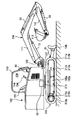
- FIG. 1 is a diagram showing the appearance of the hydraulic excavator according to the present embodiment.
- the hydraulic excavator is a swing-type front work machine that is rotatably mounted on the lower traveling body 101, the upper slewing body 102 mounted on the lower traveling body, and the front part of the upper slewing body so as to be rotatable in the vertical direction.
- the front working machine 104 includes the 104, and is composed of a boom 111, an arm 112, and a bucket 113.
- the upper swivel body 102 and the lower traveling body 101 are rotatably connected by a swivel wheel 215, and the upper swivel body 102 can be swiveled with respect to the lower traveling body 101 by the rotation of the swivel motor 43.
- a swing post 103 is attached to the front portion of the upper swing body 102, and a front working machine 104 is attached to the swing post 103 so as to be able to move up and down.
- the swing post 103 can rotate in the horizontal direction with respect to the upper swing body 102 by expanding and contracting the swing cylinder (not shown), and the boom 111, arm 112, and bucket 113 of the front working machine 104 are the first and second.
- the boom cylinder 13, the arm cylinder 23, and the bucket cylinder 33 which are the third front actuators, can be expanded and contracted to rotate in the vertical direction.
- the left and right traveling devices 105a and 105b and the blade 106 that moves up and down by expanding and contracting the blade cylinder 3h are attached to the central frame of the lower traveling body 101.
- the right and left traveling devices 105a and 105b are provided with drive wheels 210a and 210b, idlers 211a and 211b, and crawler belts 212a and 212b, respectively. It runs by driving.
- a cabin 110 forming a driver's cab 108 is installed in the upper swing body 102, and a driver's seat 122, a boom cylinder 13, an arm cylinder 23, a bucket cylinder 33, and a swing motor 43 are instructed to be driven in the driver's cab 108.
- the operation lever devices 114 and 134 of the above are provided. Further, similar operation lever devices are provided for the traveling motors 3f and 3g, the blade cylinder 3h, and the swing cylinder (not shown), and these operation lever devices are also provided in the cab 108.
- FIG. 2 is a diagram showing the configuration of the drive system of the present embodiment.
- the drive system includes an engine 6 (diesel engine), a main hydraulic pump 1, and a pilot pump 51, and the hydraulic pump 1 and the pilot pump 51 are driven by the engine 6.
- the hydraulic pump 1 is connected to the pipeline 2, and a relief valve 3 is attached to the pipeline 2 via the relief pipeline 4.
- the downstream side of the relief valve 3 is connected to the tank 5.
- a pipeline 8 and a pipeline 9 are connected to the downstream of the pipeline 2.
- Pipes 11, 21, 31, and 41 are connected in parallel to the pipe 9.
- Check valves 10, 20, 30, and 40 are arranged in the pipelines 11, 21, 31, and 41, respectively.
- a directional control valve 12 is connected to the pipeline 8 and downstream of the pipeline 11, and the directional control valve 12 is also connected to the bottom conduit 13B connected to the bottom side chamber of the boom cylinder 13 and the rod side chamber of the boom cylinder 13. It is connected to the connected rod line 13R, the tank line 13T connected to the tank 5, and the center bypass line 13C.
- the directional control valve 12 is driven by the pressure of the pilot line 12b and the pressure of the pilot line 12r. When the pressure in both pilot lines is low, the directional control valve 12 is in the neutral position, the line 8 is connected to the center bypass line 13C, and the other lines are blocked. When the pressure in the pilot line 12b is high, the directional control valve 12 is switched to the upper part of the figure, the line 11 is connected to the bottom line 13B, the tank line 13T is connected to the rod line 13R, and the line 8 and the center are connected. The bypass line 13C is cut off.
- the directional control valve 12 When the pressure in the pilot line 12r is high, the directional control valve 12 is switched to the lower part of the figure, the line 11 is connected to the rod line 13R, the tank line 13T is connected to the bottom line 13B, and the line 8 and the center are connected.
- the bypass line 13C is cut off.
- a directional control valve 22 is connected to the pipeline 13C and the downstream of the pipeline 21.
- the directional control valve 22 also includes a bottom pipeline 23B connected to the bottom side chamber of the arm cylinder 23, a rod pipeline 23R connected to the rod side chamber of the arm cylinder 23, and a tank pipeline connected to the tank 5. It is connected to 23T and center bypass pipeline 23C.
- the directional control valve 22 is driven by the pressure of the pilot line 22b and the pressure of the pilot line 22r. When the pressure in both pilot lines is low, the directional control valve 22 is in the neutral position, the center bypass line 13C is connected to the center bypass line 23C, and the other lines are blocked. When the pressure in the pilot line 22b is high, the directional control valve 22 is switched upward in the figure, the line 21 is connected to the bottom line 23B, the tank line 23T is connected to the rod line 23R, and the center bypass line 13C is connected. And the center bypass pipeline 23C is cut off.
- the direction control valve 22 is switched to the lower part in the figure, the line 21 is connected to the rod line 23R, the tank line 23T is connected to the bottom line 23B, and the center bypass line 13C is connected. And the center bypass pipeline 23C is cut off.
- a directional control valve 32 is connected to the pipeline 23C and downstream of the pipeline 31, and the directional control valve 32 is also connected to the bottom side chamber of the bucket cylinder 33, the bottom pipeline 33B, and the rod side chamber of the bucket cylinder 33. It is connected to the rod pipeline 33R connected to the tank 5, the tank pipeline 33T connected to the tank 5, and the center bypass pipeline 33C.
- the directional control valve 32 is driven by the pressure of the pilot line 32b and the pressure of the pilot line 32r. When the pressure in both pilot lines is low, the directional control valve 32 is in the neutral position, the center bypass line 23C is connected to the center bypass line 33C, and the other lines are blocked. When the pressure in the pilot line 32b is high, the direction control valve 32 is switched upward in the figure, the line 31 is connected to the bottom line 33B, the tank line 33T is connected to the rod line 33R, and the center bypass line 23C is connected. And the center bypass pipeline 33C is cut off.
- the direction control valve 32 When the pressure in the pilot line 32r is high, the direction control valve 32 is switched to the lower part in the figure, the line 31 is connected to the rod line 33R, the tank line 33T is connected to the bottom line 33B, and the center bypass line 23C is connected. And the center bypass pipeline 33C is cut off.
- a directional control valve 42 is connected to the pipeline 33C and downstream of the pipeline 41, and the directional control valve 42 is also connected to the counterclockwise side chamber of the swivel motor 43. It is connected to the right rotation line 43R connected to the right rotation side chamber, the tank line 43T connected to the tank 5, and the center bypass line 43C.
- the center bypass pipeline 43C is connected to the tank 5.
- the directional control valve 42 is driven by the pressure of the pilot line 42l and the pressure of the pilot line 42r. When the pressure in both pilot lines is low, the directional control valve 42 is in the neutral position, the center bypass line 33C is connected to the center bypass line 43C, and the other lines are blocked. When the pressure of the pilot line 42l is high, the direction control valve 42 is switched to the upper part in the figure, the line 41 is connected to the left rotation line 43L, the tank line 43T is connected to the right rotation line 43R, and the center bypass pipe is connected. Road 33C and center bypass line 43C are cut off.
- the pilot pump 51 is connected to the pilot pipeline 52.
- the downstream from the pilot line 52 will be described later with reference to FIG.
- the hydraulic drive system is equipped with similar directional control valves for the traveling motors 3f and 3g shown in FIG. 1, the blade cylinder 3h, and the swing cylinder (not shown), and connects and disconnects the pipelines. Can be done.
- the engine 6 and the hydraulic pump 1 constitute a power source
- the boom cylinder 13, arm cylinder 23, bucket cylinder 33, swivel motor 43, traveling motor 3f, 3g, blade cylinder 3h, and swing cylinder (not shown) are derived from the power source. It constitutes a plurality of actuators that operate by receiving power.
- the operating lever devices 114 and 134 shown in FIG. 1 and a plurality of operating levers of other operating lever devices (not shown) each indicate the amount of power to be distributed to the plurality of actuators, and the directional control valves 12, 22, 32, 42 and the illustrated operating levers are shown.
- Other directional control valves distribute power to multiple actuators based on instructions from multiple operating levers.
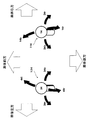
- FIG. 3 is a diagram for explaining the movable direction and the definition of the movable direction of the operating levers of the operating lever devices 114 and 134 in the first embodiment.
- right and left operating lever devices 114 and 134 are installed in the cab 108 of the hydraulic excavator, and the operator holds the operating lever 14 (first operating lever) of the operating lever device 114 with his right hand and his left hand. Operates the operation lever 34 (second operation lever) of the operation lever device 134.
- the operating lever devices 114 and 134 can operate two actuators with one operating lever 14 or 34, respectively.
- the operating levers 14 and 34 can be operated from the neutral position, respectively, and the operations of the operating lever 14 in the front direction 14b and the rear direction 14r correspond to the boom lowering and boom raising operations of the boom cylinder 13 and to the right of the operating lever 14.
- the operation of 24r and the left direction 24b corresponds to the operation of the bucket dump and the bucket cloud of the bucket cylinder 33
- the operation of the right direction 34b and the left direction 34r of the operation lever 34 corresponds to the operation of the arm cloud and the arm dump of the arm cylinder 23
- the operation of the operating lever 34 in the forward direction 44l and the backward direction 44r corresponds to the right-turning and left-turning operations of the turning motor 43.
- the forward direction, the rear direction, the right direction, and the left direction mean the front direction, the rear direction, the right direction, and the left direction of the upper swivel body 102 which is a vehicle body.
- the operating levers 14 and 34 of the operating lever devices 114 and 134 can be operated in a plurality of directions from the neutral position, and among the plurality of actuators (boom cylinder 13, arm cylinder 23, bucket cylinder 33, swivel motor 43). Operate different actuators.
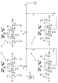
- FIG. 4 is a diagram showing the configuration of the operation system of the drive system.
- the operating lever devices 114 and 134 are of the hydraulic pilot system, and the operating lever device 114 is a boom pilot valve 15b, 15r and a bucket pilot valve 25b driven by the operating lever 14 (first lever). , 25r, and the operating lever device 134 has pilot valves 35b and 35r for the arm driven by the operating lever 34 (second lever) and pilot valves 45l and 45r for turning.
- the operating lever may be simply referred to as a "lever".
- the pipelines 19, 29, 39, 49 and the relief valve 53 are connected in parallel to the downstream of the pilot pipeline 52.
- a tank 5 is connected downstream of the relief valve 53.
- the pipelines 19, 29, 39, and 49 are provided with throttle portions 94, 95, 96, and 97, respectively.
- the pilot valve 15b of the operating lever device 114 is connected to the pipe line 19 and is connected to the pipe line 18 and the pipe line 16b.
- the pipeline 16b is connected to the pilot pipeline 12b (see FIG. 2).
- a pressure sensor 17b is mounted on the pipeline 16b.
- the pipeline 18 is connected to the tank 5.
- the pilot valve 15b When the lever 14 is in the neutral position, the pilot valve 15b connects the conduit 18 and the conduit 16b and shuts off the conduit 19. When the lever 14 is operated in the forward direction 14b, the pilot valve 15b connects the conduit 19 and the conduit 16b and shuts off the conduit 18. At this time, a pressure (operating pressure) corresponding to the operating amount of the lever 14 is generated in the pipeline 16b.
- the pressure sensor 17b measures the pressure in the pipeline 16b and transmits a signal to the electrically connected controller 50.
- the pilot valve 15r of the operating lever device 114 is connected to the pipe line 19 and is connected to the pipe line 18 and the pipe line 16r.
- the pipeline 16r is connected to the pilot pipeline 12r (see FIG. 2).
- a pressure sensor 17r is mounted on the pipeline 16r.
- the pipeline 18 is connected to the tank 5.
- the pilot valve 15r When the lever 14 is in the neutral position, the pilot valve 15r connects the conduit 18 and the conduit 16r and shuts off the conduit 19. When the lever 14 is operated in the backward direction 14r, the pilot valve 15r connects the conduit 19 and the conduit 16r and shuts off the conduit 18. At this time, a pressure (operating pressure) corresponding to the operating amount of the lever 14 is generated in the pipeline 16r.
- the pressure sensor 17r measures the pressure in the pipeline 16r and transmits a signal to the electrically connected controller 50.
- the pilot valve 25b of the operating lever device 114 is connected to the conduit 29 and is connected to the conduit 28 and the conduit 26b.
- the pipeline 26b is connected to the pilot pipeline 32b (see FIG. 2).
- a pressure sensor 27b is mounted on the pipeline 26b.
- the pipeline 28 is connected to the tank 5.
- the pilot valve 25b When the lever 14 is in the neutral position, the pilot valve 25b connects the conduit 28 and the conduit 26b and shuts off the conduit 29. When the lever 14 is operated to the left 24b, the pilot valve 25b connects the conduit 29 and the conduit 26b and shuts off the conduit 28. At this time, a pressure (operating pressure) corresponding to the operating amount of the lever 14 is generated in the pipeline 26b.
- the pressure sensor 27b measures the pressure in the pipeline 26b and transmits a signal to the electrically connected controller 50.
- the pilot valve 25r of the operating lever device 114 is connected to the pipe line 29, and is connected to the pipe line 28 and the pipe line 26r.
- the pipeline 26r is connected to the pilot pipeline 32r (see FIG. 2).
- a pressure sensor 27r is mounted on the pipeline 26r.
- the pipeline 28 is connected to the tank 5.
- the pilot valve 25r When the lever 14 is in the neutral position, the pilot valve 25r connects the conduit 28 and the conduit 26r and shuts off the conduit 29. When the lever 14 is operated to the right 24r, the pilot valve 25r connects the conduit 29 and the conduit 26r and shuts off the conduit 28. At this time, a pressure (operating pressure) corresponding to the operating amount of the lever 14 is generated in the pipeline 26r.
- the pressure sensor 27r measures the pressure in the pipeline 26r and transmits a signal to the electrically connected controller 50.
- the pilot valve 35b of the operating lever device 134 is connected to the pipe line 39, and is connected to the pipe line 38 and the pipe line 36b.
- the pipeline 36b is connected to the pilot pipeline 22b (see FIG. 2).
- a pressure sensor 37b is mounted on the pipeline 36b.
- the pipeline 38 is connected to the tank 5.
- the pilot valve 35b When the lever 34 is in the neutral position, the pilot valve 35b connects the conduit 38 and the conduit 36b and shuts off the conduit 39. When the lever 34 is operated to the right 34b, the pilot valve 35b connects the conduit 39 and the conduit 36b and shuts off the conduit 38. At this time, a pressure (operating pressure) corresponding to the operating amount of the lever 34 is generated in the pipeline 36b.
- the pressure sensor 37b measures the pressure in the pipeline 36b and transmits a signal to the electrically connected controller 50.
- the pilot valve 35r of the operating lever device 134 is connected to the pipe line 39, and is connected to the pipe line 38 and the pipe line 36r.
- the pipeline 36r is connected to the pilot pipeline 22r (see FIG. 2).
- a pressure sensor 37r is mounted on the pipeline 36r.
- the pipeline 38 is connected to the tank 5.
- the pilot valve 35r When the lever 34 is in the neutral position, the pilot valve 35r connects the conduit 38 and the conduit 36r and shuts off the conduit 39. When the lever 34 is operated to the left 34r, the pilot valve 35r connects the conduit 39 and the conduit 36r and shuts off the conduit 38. At this time, a pressure (operating pressure) corresponding to the operating amount of the lever 34 is generated in the pipeline 36r.
- the pressure sensor 37r measures the pressure in the pipeline 36r and transmits a signal to the electrically connected controller 50.
- the pilot valve 45l of the operating lever device 134 is connected to the pipe line 49, and is connected to the pipe line 48 and the pipe line 46l.
- the pipeline 46l is connected to the pilot pipeline 42l (see FIG. 2).
- a pressure sensor 47l is mounted on the pipeline 46l.
- the pipeline 48 is connected to the tank 5.
- the pilot valve 45l When the lever 34 is in the neutral position, the pilot valve 45l connects the conduit 48 and the conduit 46l and shuts off the conduit 49. When the lever 34 is operated in the forward direction 44l, the pilot valve 45l connects the conduit 49 and the conduit 46l and shuts off the conduit 48. At this time, a pressure (operating pressure) corresponding to the operating amount of the lever 34 is generated in the pipeline 46l.
- the pressure sensor 47l measures the pressure in the pipeline 46l and transmits a signal to the electrically connected controller 50.
- the pilot valve 45r of the operating lever device 134 is connected to the pipe line 49, and is connected to the pipe line 48 and the pipe line 46r.
- the pipeline 46r is connected to the pilot pipeline 42r (see FIG. 2).
- a pressure sensor 47r is mounted on the pipeline 46r.
- the pipeline 48 is connected to the tank 5.
- the pilot valve 45r When the lever 34 is in the neutral position, the pilot valve 45r connects the conduit 48 and the conduit 46r and shuts off the conduit 49. When the lever 34 is operated in the backward direction 44r, the pilot valve 45r connects the pipe line 49 and the pipe line 46r and shuts off the pipe line 48. At this time, a pressure (operating pressure) corresponding to the operating amount of the lever 34 is generated in the pipeline 46r.
- the pressure sensor 47r measures the pressure in the pipeline 46r and transmits a signal to the electrically connected controller 50.
- the pressure sensors 17b, 17r, 27b, 27r, 37b, 37r, 47l, 47r constitute a plurality of operation state detection devices for detecting the operation state of the operation lever devices 114, 134. Further, the pressure sensors 17b and 17r constitute a first operation state detection device that detects the operation state of the operation lever 14 in the front-rear direction, and the pressure sensors 27b and 27r detect the operation state of the operation lever 14 in the right and left directions.
- the second operation state detection device is configured, the pressure sensors 37b and 37r constitute a third operation state detection device that detects the operation state in the right and left directions of the operation lever 34, and the pressure sensors 47l and 47r are the operation lever 34.
- a fourth operation state detection device for detecting an operation state in the front-rear direction is configured.
- the operation system is provided with a similar pressure sensor (operation state detection device) for operation lever devices other than the operation lever devices 114 and 134, and is based on the operation state of those operation levers.
- the power reduction control described later can be performed.
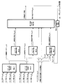
- the drive system of the present embodiment further includes a controller 50, a switch 76, and a target rotation speed indicator 77.
- the controller 50 is electrically connected to the pressure sensors 17b, 17r, 27b, 27r, 37b, 37r, 47l, 47r, the switch 76, and the target rotation speed indicator 77.
- the controller 50 receives the respective measured pressure signals from the pressure sensors 17b to 47r, the signal from the switch 76, and the signal from the target rotation speed indicator 77, and based on these signals, the target rotation for controlling the engine 6.
- the number is calculated, and a command signal of the target rotation speed is transmitted to the rotation speed control device 7 of the engine 6 electrically connected to the controller 50.
- the rotation speed control device 7 controls the engine 6 so as to reach the target rotation speed.
- the switch 76 is a switch that switches whether to set the power reduction control mode by transmitting an ON or OFF signal to the controller 50. When the signal of the switch 76 is OFF, the power reduction control mode is canceled and all. The driving power of the engine 6 is not reduced even when the operating lever of the above is not operated.
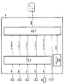
- FIG. 5 is a block diagram showing the functions of the controller 50.
- the controller 50 is based on the operating states of the operating levers 14 and 34 (plural operating levers) detected by the pressure sensors 17b, 17r, 27b, 27r, 37b, 37r, 47l, 47r (plural operating state detecting devices). , When at least one of the operating levers 14 and 34 is operated to a non-operating state in which all the operating levers 14 and 34 are not operated and the non-operating time of the operating levers 14 and 34 elapses. In addition, the power reduction control of the engine 6 and the hydraulic pump 1 (power source) is performed, and when at least one of the operation levers 14 and 34 is operated while the power reduction control is being performed, the power reduction control is released.
- the above set time is set to the first set time. If Tth1 is set and the time until at least one operating lever shifts to the non-operating state is shorter than the preset monitoring time Tth0, the above set time is set to the second set time Tth2, which is shorter than the first set time Tth1.
- the controller 50 changes the operating states of the operating levers 14 and 34 (plural operating levers) detected by the pressure sensors 17b, 17r, 27b, 27r, 37b, 37r, 47l, 47r (plural operating state detecting devices). Based on this, the non-operation flags F14 (t) and F34 (t) (non-operation state information) indicating that the operation levers 14 and 34 are in the non-operation state and the power reduction flag F50 indicating that the power reduction control is performed. (t) (Power reduction control status information) is generated, and the non-power reduction time without power reduction control is calculated based on the non-operation flags F14 (t) and F34 (t) and the power reduction flag F50 (t). However, this non-power reduction time is used as the operation time of the operation levers 14 and 34.
- the controller 50 shifts from the state in which at least one of the operating levers is operated to the non-operating state in which none of the operating levers 14 and 34 is operated, the at least one operating lever has a monitoring time Tth0. If there is no operation in the meantime, it is determined that the operation of at least one of the operating levers is an erroneous operation.
- the controller 50 has the functions of the sensor signal conversion unit 50a, the constant / table storage unit 50b, and the power calculation unit 50c.
- the sensor signal conversion unit 50a receives the signals sent from the pressure sensors 17b to 47r and the switch 76, and converts them into pressure information and switch flag information.
- the sensor signal conversion unit 50a transmits the converted pressure information and switch flag information to the power calculation unit 50c.
- the pressure information converted by the sensor signal conversion unit 50a is the pressure generated in the pipelines 16b to 46r by driving the pilot valves 15b to 45r.
- the sensor values P17b (t), P17r (t), P27b (t), P27r (t), P37b (t), P37r (t), P47l (t), P47r (t) are sometimes called "operating pressure". .. Further, the switch information converted by the sensor signal conversion unit 50a is shown as the switch flag Fsw (t) in FIG.
- the constant / table storage unit 50b stores constants and tables required for calculation, and transmits the information to the power calculation unit 50c. Constants-The constants stored in the table storage unit 50b include the monitoring time Tth0, the first set time Tth1, and the second set time Tth2.
- the power calculation unit 50c has pressure information and switch flag information transmitted from the sensor signal conversion unit 50a, target rotation speed information transmitted from the target rotation speed indicating device 77, and constants and constants transmitted from the table storage unit 50b. It receives information (monitoring time Tth0, first set time Tth1, second set time Tth2) and table information, and calculates the target rotation speed of the engine 6. Then, the power calculation unit 50c outputs the target rotation speed for control to the rotation speed control device 7.
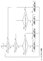
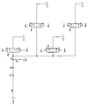
- FIG. 6 is a block diagram showing the functions of the power calculation unit 50c. It is assumed that the sampling time of the controller 50 is ⁇ t.
- the power calculation unit 50c is the lever 14 operation state determination unit 50c-1, the lever 34 operation state determination unit 50c-2, the lever 14 non-operation time measurement unit 50c-3, and the lever 34 non-operation time measurement unit 50c-. 4. It has the functions of the power reduction determination unit 50c-5, the delay element 50c-6, and the non-power reduction time measurement unit 50c-7.
- the lever 14 operation state determination unit 50c-1 determines whether or not the lever 14 is operated from the sensor values P17b (t), P17r (t), P27b (t), and P27r (t), and the lever 14 non-operation flag. Output F14 (t).
- the lever 14 non-operation flag F14 (t) is set to true, and when it is determined that the lever 14 is operated, the lever 14 non-operation flag F14 Set (t) to false, respectively.
- the lever 14 non-operation flag F14 (t) (hereinafter, may be simply referred to as flag information F14 (t)) is transmitted to the lever 14 non-operation time measurement unit 50c-3 and the non-power reduction time measurement unit 50c-7. NS.
- the lever 34 operation state determination unit 50c-2 determines whether or not the lever 34 is operated from the sensor values P37b (t), P37r (t), P47l (t), and P47r (t), and the lever 34 non-operation flag. Output F34 (t).
- the lever 34 non-operation state determination unit 50c-2 determines that the lever 34 is non-operation
- the lever 34 non-operation flag F34 (t) is set to true, and when it is determined that the lever 34 is operated, the lever 34 non-operation flag is set. Set F34 (t) to false respectively.
- This lever 34 non-operation flag F34 (t) (hereinafter, may be simply referred to as flag information F34 (t)) is transmitted to the lever 34 non-operation time measurement unit 50c-4 and the non-power reduction time measurement unit 50c-7. ..
- the lever 14 non-operating time measuring unit 50c-3 measures the lever 14 non-operating time Tu14 (t) based on the flag information F14 (t), and the lever 14 non-operating time Tu14 (t) (hereinafter simply, the time information Tu14 (t)). ) May be transmitted to the power reduction determination unit 50c-5.
- the lever 34 non-operating time measuring unit 50c-4 measures the lever 34 non-operating time Tu34 (t) based on the flag information F34 (t), and the lever 34 non-operating time Tu34 (t) (hereinafter simply, the time information Tc14 (t)). ) May be transmitted to the power reduction determination unit 50c-5.
- the non-power reduction time measuring unit 50c-7 is based on the flag information F14 (t) and the flag information F34 (t) and the power reduction flag F50 (t- ⁇ t) one step before generated by the delay element 50c-6.
- the non-power reduction time TF50 (t) is measured, and the non-power reduction time TF50 (t) (hereinafter, may be simply referred to as time information TF50 (t)) is transmitted to the power reduction determination unit 50c-5.
- the power reduction determination unit 50c-5 has time information Tu14 (t), Tu34 (t), time information TF50 (t), a switch flag Fsw (t), and a target rotation speed transmitted from the target rotation speed indicator 77. Based on the above, it is determined whether or not to reduce the control target rotation speed, and based on the determination result, the control target rotation speed and the power reduction flag F50 (t) are output. Further, the power reduction determination unit 50c-5 sets the power reduction flag F50 (t) to true when it determines that the target rotation speed is reduced, and sets the power reduction flag F50 (t) to false when it determines that the target rotation speed is not reduced. Set to.
- FIG. 7 is a flowchart showing a calculation flow of the lever 14 operation state determination unit 50c-1. This calculation flow is repeatedly processed for each sampling time ⁇ t, for example, while the controller 50 is operating.
- step S101 the calculation of the lever 14 operation state determination unit 50c-1 starts.
- step S102 the lever 14 operation state determination unit 50c-1 determines whether the sensor value P17b (t) is equal to or less than the threshold value Pth. If the sensor value P17b (t) is equal to or less than the threshold value Pth, it is determined as Yes, and the process proceeds to step S103. If the sensor value P17b (t) is larger than the threshold value Pth, it is determined as No, and the process proceeds to step S107.
- step S103 the lever 14 operation state determination unit 50c-1 determines whether the sensor value P17r (t) is equal to or less than the threshold value Pth. If the sensor value P17r (t) is equal to or less than the threshold value Pth, it is determined as Yes, and the process proceeds to step S104. If the sensor value P17r (t) is larger than the threshold value Pth, it is determined as No, and the process proceeds to step S107.
- step S104 the lever 14 operation state determination unit 50c-1 determines whether the sensor value P27b (t) is equal to or less than the threshold value Pth. If the sensor value P27b (t) is equal to or less than the threshold value Pth, it is determined as Yes, and the process proceeds to step S105. If the sensor value P27b (t) is larger than the threshold value Pth, it is determined as No, and the process proceeds to step S107.
- step S105 the lever 14 operation state determination unit 50c-1 determines whether the sensor value P27r (t) is equal to or less than the threshold value Pth. If the sensor value P27r (t) is equal to or less than the threshold value Pth, it is determined as Yes, and the process proceeds to step S106. If the sensor value P27r (t) is larger than the threshold value Pth, it is determined as No, and the process proceeds to step S107.
- step S106 the lever 14 operation state determination unit 50c-1 determines that the lever 14 is not operated and sets the lever 14 non-operation flag F14 (t) to true. Then, the flag information is transmitted to the lever 14 operation time measuring unit 50c-3 and the power reduction determining unit 50c-5.
- step S107 the lever 14 operation state determination unit 50c-1 determines that the lever 14 is being operated, and sets the lever 14 non-operation flag F14 (t) to false. Then, the flag information is transmitted to the lever 14 operation time measuring unit 50c-3 and the power reduction determining unit 50c-5.
- FIG. 8 is a flowchart showing a calculation flow of the lever 34 operation state determination unit 50c-2. This calculation flow is repeatedly processed for each sampling time ⁇ t, for example, while the controller 50 is operating.
- step S201 the calculation of the lever 34 operation state determination unit 50c-2 starts.
- step S202 the lever 34 operation state determination unit 50c-2 determines whether the sensor value P37b (t) is equal to or less than the threshold value Pth. If the sensor value P37b (t) is equal to or less than the threshold value Pth, it is determined as Yes, and the process proceeds to step S203. If the sensor value P37b (t) is larger than the threshold value Pth, it is determined as No, and the process proceeds to step S207.
- step S203 the lever 34 operation state determination unit 50c-2 determines whether the sensor value P37r (t) is equal to or less than the threshold value Pth. If the sensor value P37r (t) is equal to or less than the threshold value Pth, it is determined as Yes, and the process proceeds to step S204. If the sensor value P37r (t) is larger than the threshold value Pth, it is determined as No, and the process proceeds to step S207.
- step S204 the lever 34 operation state determination unit 50c-2 determines whether the sensor value P47l (t) is equal to or less than the threshold value Pth. If the sensor value P47l (t) is equal to or less than the threshold value Pth, it is determined as Yes, and the process proceeds to step S205. If the sensor value P47l (t) is larger than the threshold value Pth, it is determined as No, and the process proceeds to step S207.
- step S205 the lever 34 operation state determination unit 50c-2 determines whether the sensor value P47r (t) is equal to or less than the threshold value Pth. If the sensor value P47r (t) is equal to or less than the threshold value Pth, it is determined as Yes, and the process proceeds to step S206. If the sensor value P47r (t) is larger than the threshold value Pth, it is determined as No, and the process proceeds to step S207.
- step S206 the lever 34 operation state determination unit 50c-2 determines that the lever 34 is not operated and sets the lever 34 non-operation flag F34 (t) to true. Then, the flag information is transmitted to the lever 34 operation time measuring unit 50c-4 and the power reduction determining unit 50c-5.
- step S207 the lever 34 operation state determination unit 50c-2 determines that the lever 14 is being operated and sets the lever 34 non-operation flag F34 (t) to false. Then, the flag information is transmitted to the lever 34 operation time measuring unit 50c-4 and the power reduction determining unit 50c-5.
- FIG. 9 shows the relationship between the sensor value P17b (t) or P17r (t) and the meter-in opening area of the directional control valve 12.
- the sensor value P17b (t) or P17r (t) is described as "operating pressure”.
- the meter-in opening does not open until the operating pressure P17b (t) or P17r (t) reaches the value of Pth, so the hydraulic cylinder (boom cylinder) 13 does not operate.
- the operation state determination units 50c-1 and 50c-2 use the pressure value Pth at which the meter-in opening opens as a threshold value.
- FIG. 10 is a flowchart showing a calculation flow of the lever 14 non-operation time measuring unit 50c-3. This calculation flow is repeatedly processed for each sampling time ⁇ t, for example, while the controller 50 is operating.
- step S301 the calculation of the lever 14 non-operation time measuring unit 50c-3 starts.
- step S302 the lever 14 non-operation time measuring unit 50c-3 determines whether the lever 14 non-operation flag F14 (t) is true. If the lever 14 non-operation flag F14 (t) is true, it is determined as Yes, and the process proceeds to step S303. If the lever 14 non-operation flag F14 (t) is false, it is determined as No, and the process proceeds to step S304.
- the lever 14 non-operating time measuring unit 50c-3 adds the sampling time ⁇ t to the lever 14 non-operating time Tu14 (t- ⁇ t) one step before the holding. The value is set as a new lever 14 non-operation time Tu14 (t). Then, the information is transmitted to the power reduction determination unit 50c-5.
- the lever 14 non-operating time measuring unit 50c-3 sets the lever 14 non-operating time Tu14 (t) to 0. Then, the information is transmitted to the power reduction determination unit 50c-5.
- FIG. 11 is a flowchart showing a calculation flow of the lever 34 non-operation time measuring unit 50c-4. This calculation flow is repeatedly processed for each sampling time ⁇ t, for example, while the controller 50 is operating.
- step S401 the calculation of the lever 34 non-operation time measuring unit 50c-4 starts.
- step S402 the lever 34 non-operation time measuring unit 50c-4 determines whether the lever 34 non-operation flag F34 (t) is true. If the lever 34 non-operation flag F34 (t) is true, it is determined as Yes, and the process proceeds to step S403. If the lever 34 non-operation flag F34 (t) is false, it is determined as No, and the process proceeds to step S404.
- the lever 34 non-operating time measuring unit 50c-4 adds the sampling time ⁇ t to the lever 34 non-operating time Tu34 (t- ⁇ t) one step before the holding. The value is set as a new lever 34 non-operation time Tu34 (t). Then, the information is transmitted to the power reduction determination unit 50c-5.
- the lever 34 non-operating time measuring unit 50c-4 sets the lever 34 non-operating time Tu34 (t) to 0. Then, the information is transmitted to the power reduction determination unit 50c-5.
- FIG. 12 is a flowchart showing a calculation flow of the non-power reduction time measuring unit 50c-7. This calculation flow is repeatedly processed for each sampling time ⁇ t, for example, while the controller 50 is operating.
- step S1401 the calculation of the non-power reduction time measuring unit 50c-7 starts.
- step S1402 the non-power reduction time measuring unit 50c-7 determines whether the power reduction flag F50 (t- ⁇ t) one step before is false. If the power reduction flag F50 (t- ⁇ t) is false, it is determined as Yes, and the process proceeds to step S1403. If the power reduction flag F50 (t- ⁇ t) is true, it is determined as No, and the process proceeds to step S1407.
- step S1403 the non-power reduction time measuring unit 50c-7 determines whether the lever 14 non-operation flag F14 (t) is true. If the lever 14 non-operation flag F14 (t) is true, it is determined as Yes, and the process proceeds to step S1404. If the lever 14 non-operation flag F14 (t) is false, it is determined as No, and the process proceeds to step S1406.
- step S1404 the non-power reduction time measuring unit 50c-7 determines whether the lever 34 non-operation flag F34 (t) is true. If the lever 34 non-operation flag F34 (t) is true, it is determined as Yes, and the process proceeds to step S1405. If the lever 34 non-operation flag F34 (t) is false, it is determined as No, and the process proceeds to step S1406.
- step S1406 the power reduction flag F50 (t- ⁇ t) is false and is not in the power reduction state, and at least one of the lever 14 non-operation flag F14 (t) and the lever 34 non-operation flag F34 (t) is not true (lever). Since at least one of 14 and 34 is operated), the non-power reduction time measuring unit 50c-7 adds the value obtained by adding the sampling time ⁇ t to the non-power reduction time TF50 (t- ⁇ t) one step before. Set as the power reduction time TF50 (t). Then, the information is transmitted to the power reduction determination unit 50c-5.
- step S1405 when the power reduction flag F50 (t- ⁇ t) is false and not in the power reduction state, both the lever 14 non-operation flag F14 (t) and the lever 34 non-operation flag F34 (t) become true (
- the non-power reduction time measuring unit 50c-7 changes the non-power reduction time TF50 (t- ⁇ t) one step before to the new non-power reduction time TF50 (t).
- the non-power reduction time TF50 (t- ⁇ t) one step before is held as the non-power reduction time TF50 (t). Then, the information is transmitted to the power reduction determination unit 50c-5.
- non-power reduction time TF50 (t) set in step S1405 non-power reduction time TF50 (t- ⁇ t) one step before
- at least one of the levers 14 and 34 is operated (power reduction control is performed). It means the operation time from the time when both the levers 14 and 34 are not operated (the power reduction control is performed again).
- step S1407 the power reduction flag F50 (t- ⁇ t) is not false and is in the power reduction state, so the non-power reduction time measuring unit 50c-7 sets the non-power reduction time TF50 (t) to 0. Then, the information is transmitted to the power reduction determination unit 50c-5.
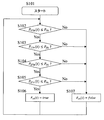
- FIG. 13 is a flowchart showing a calculation flow of the power reduction determination unit 50c-5. This calculation flow is repeatedly processed for each sampling time ⁇ t, for example, while the controller 50 is operating.
- step S501 the calculation of the power reduction determination unit 50c-5 starts.
- step S502 the power reduction determination unit 50c-5 determines whether the switch flag Fsw (t) is true. If the switch flag Fsw (t) is true, it is determined as Yes, and the process proceeds to step S503. If the switch flag Fsw (t) is false, it is determined as No, and the process proceeds to step S509.
- step S503 the power reduction determination unit 50c-5 determines whether the non-power reduction time TF50 (t) is equal to or longer than the preset erroneous operation monitoring time Tth0 of the lever 14 or 34. If the non-power reduction time TF50 (t) is equal to or longer than the monitoring time Tth0, it is determined as Yes, and the process proceeds to step S504. If the non-power reduction time TF50 (t) is smaller than the monitoring time Tth0, it is determined as No, and the process proceeds to step S505.
- the non-power reduction time TF50 (t) corresponds to the operation time from the start of operation of the operation levers 14 and 34 as described above.
- the non-power reduction time TF50 (t) is not used as the operation time, but the sensor values P17b (t), P17r (t), P27b (t), P27r (t), P37b (t) of the pressure sensors 17b to 47r. ), P37r (t), P47l (t), P47r (t) (operating pressure) may be directly used to calculate the operating time of the levers 14 and 37, and the operating time may be used.
- step S504 the power reduction determination unit 50c-5 sets the first setting in which the smaller value of the lever 14 non-operation time Tu14 (t) and the lever 34 non-operation time Tu34 (t) is the normal power reduction control time. Determine if the time is Tth1 or higher. If the smaller value of the lever 14 non-operating time Tu14 (t) and the lever 34 non-operating time Tu34 (t) is equal to or greater than the first set time Tth1, it is determined as Yes, and the process proceeds to step S506. If the smaller value of the lever 14 non-operating time Tu14 (t) and the lever 34 non-operating time Tu34 (t) is smaller than the first set time Tth1, it is determined as No, and the process proceeds to step S507.
- step S505 the power reduction determination unit 50c-5 determines whether the smaller value of the lever 14 non-operating time Tu14 (t) and the lever 34 non-operating time Tu34 (t) is the second set time Tth2 or more. If the smaller value of the lever 14 non-operating time Tu14 (t) and the lever 34 non-operating time Tu34 (t) is equal to or greater than the second set time Tth2, it is determined as Yes, and the process proceeds to step S508. If the smaller value of the lever 14 non-operating time Tu14 (t) and the lever 34 non-operating time Tu34 (t) is smaller than the second set time Tth2, it is determined as No, and the process proceeds to step S509.
- the second set time Tth2 is set shorter than the first set time Tth1, which is the normal power reduction control time.
- the first set time Tth1 is, for example, 3 to 5 seconds
- the second set time Tth2 is, for example, 0.5 to 2 seconds.
- the monitoring time Tth0 is set to the maximum value of the time that can be regarded as an erroneous operation of the lever 14 or 34, whereby the operating time of the lever 14 or 34 (non-power reduction time TF50 (t)) during the monitoring time Tth0. If the operation time is shorter than the monitoring time Tth0, it can be judged as an erroneous operation.
- the maximum value of the operation time that can be regarded as an erroneous operation of the lever 14 or 34 can be determined by collecting the operation time data in advance.
- the monitoring time Tth0 is, for example, 1 to 2.5 seconds.
- step S506 and step S508 the power reduction determination unit 50c-5 performs the same processing. That is, in step S506 and step S508, the power reduction determination unit 50c-5 sets the power reduction flag to true, and at the same time, indicates the target rotation speed for controlling the engine 6 by the target rotation speed indicating device 77. Set the target rotation speed for power reduction control lower than the target rotation speed. Then, the target rotation speed is transmitted to the rotation speed control device 7. The rotation speed control device 7 reduces the rotation speed of the engine 6 by reducing the amount of fuel supplied to the engine 6. In this way, the power reduction determination unit 50c-5 performs power reduction control in steps S506 and S508.
- step S507 and step S509 the power reduction determination unit 50c-5 performs the same processing. That is, in step S507 and step S509, the power reduction determination unit 50c-5 sets the power reduction flag F50 (t) to false, and at the same time, indicates the target rotation speed for controlling the engine 6 by the target rotation speed indicating device 77. Set to the normal target speed to be set. Then, the target rotation speed is transmitted to the rotation speed control device 7. The rotation speed control device 7 increases the rotation speed of the engine 6 by increasing the amount of fuel supplied to the engine 6. In this way, the power reduction determination unit 50c-5 releases the power reduction control in steps S507 and S509.
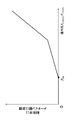
- FIG. 14 is a time chart showing a transition example of the operating pressure and the target rotation speed when the levers 14 and 34 are operated.
- the upper graph of FIG. 14 shows the time change of the operating pressure P17b (t) by the lever 14, the center graph shows the time change of the operating pressure P37b (t) by the lever 34, and the lower graph shows the time change of the target rotation speed. , Each is shown.
- the horizontal axis is time (seconds) for all graphs.
- the upper graph and the center graph also show the operating pressure threshold Pth.
- step S507 of FIG. 13 is performed (S502 ⁇ S503 ⁇ S504 ⁇ S507), and the target rotation speed for controlling the engine 6 is set to the normal value Nh instructed by the target rotation speed indicator 77. ing. That is, the power reduction control (auto idle control) is canceled.
- step S507 of FIG. 13 is performed (S502 ⁇ S503 ⁇ S504 ⁇ S507), and the target rotation speed is set to a normal value Nh.
- step S507 is performed from the time t1 until the first set time Tth1 elapses (S502 ⁇ S503 ⁇ S504 ⁇ S507), and the target rotation speed for controlling the engine 6 is set to the normal value Nh. Normal power control is performed. After that, when the first set time Tth1 elapses from the time t1, the process of step S506 in FIG.
- step S508 in FIG. 13 is performed at the time t1a (S502 ⁇ S503 ⁇ S504 ⁇ S506), and the target rotation speed for controlling the engine 6 is power reduction control. It is set to a value Nl smaller than the normal value Nh of (auto idle control), and shifts to power reduction control. After that, the power reduction control is performed and the non-power reduction time TF50 (t) becomes 0, so the process of step S508 in FIG. 13 is performed, and the power reduction control continues (S502 ⁇ S503 ⁇ S505 ⁇ S508).
- step S509 of FIG. 13 is performed (S502 ⁇ S503 ⁇ S505 ⁇ S509), the target rotation speed for control of the engine 6 returns to the normal value Nh, and the power reduction control is released.
- step S509 is performed from the time t3 until the second set time Tth2 elapses (S502 ⁇ S503 ⁇ S505 ⁇ S509), and the target rotation speed for controlling the engine 6 continues to be set to the normal value Nh. , Normal power control is performed.
- the target rotation speed for controlling the engine 6 is set to a value Nl smaller than the normal value Nh of the power reduction control (auto idle control), and the control shifts to the power reduction control.
- the time from time t2 to time t3 is the erroneous operation time of the lever 34, and the monitoring time Tth0 of the erroneous operation is set to the maximum value of the time that can be regarded as the erroneous operation. Therefore, the erroneous operation time is surely set in step 503. It is possible to monitor and shift to step S508 at the second set time Tth2, which is shorter than the first set time Tth1, and perform power reduction control.
- step S509 is performed from the time t5 until the second set time Tth2 elapses (S502 ⁇ S503 ⁇ S505 ⁇ S509), and the target rotation speed for controlling the engine 6 is the normal value Nh. It continues to be set to, and normal power control is performed. After that, when the second set time Tth2 elapses from the time t5, the process of step S508 of FIG.
- the target rotation speed for controlling the engine 6 is power reduction control. It is set to a value Nl smaller than the normal value Nh of (auto idle control), and shifts to power reduction control.
- the erroneous operation times t4 to t5 are longer than the erroneous operation times t2 to t3, but the erroneous operation monitoring time Tth0 is set to the maximum value of the time that can be regarded as an erroneous operation.
- the determination continues to be denied, and the erroneous operation is reliably monitored in step 503, and in this case as well, the process proceeds to step S508 at the second set time Tth2, which is shorter than the first set time Tth1, and the power reduction control can be performed.
- step S509 of FIG. 13 is performed (S502 ⁇ S503 ⁇ S505 ⁇ S509), the target rotation speed for controlling the engine 6 is set to a normal value Nh, and the power reduction control is released.
- the operation time from time t6 to time t7 is the operation time intended for work, and is longer than the monitoring time Tth0 for erroneous operation. Therefore, the process of step S509 is performed from the time t6 until the monitoring time Tth0 elapses (S502 ⁇ S503 ⁇ S505 ⁇ S509), and the target rotation speed for controlling the engine 6 continues to be set to the normal value Nh, which is normal. Power control is performed.
- step S507 When the monitoring time Tth0 seconds elapses from the time t6, the processing of step S507 is performed until the time t7 (S502 ⁇ S503 ⁇ S504 ⁇ S507), and in this case as well, the target rotation speed for controlling the engine 6 is set to the normal value Nh. It continues to be performed and normal power control is performed.
- step S507 is performed from the time t7 until the first set time Tth1 elapses (S502 ⁇ S503 ⁇ S504 ⁇ S507), and the target rotation speed for controlling the engine 6 continues to be set to the normal value Nh. , Normal power control is performed. After that, when the first set time Tth1 elapses from the time t7, the process of step S506 in FIG.
- step S508 in FIG. 13 is performed at the time t7a (S502 ⁇ S503 ⁇ S504 ⁇ S506), and the target rotation speed for controlling the engine 6 is power reduction control. It is set to a value Nl smaller than the normal value Nh of (auto idle control), and shifts to power reduction control. After that, the power reduction control is performed and the non-power reduction time TF50 (t) becomes 0, so the process of step S508 in FIG. 13 is performed, and the power reduction control continues (S502 ⁇ S503 ⁇ S505 ⁇ S508).
- none of the operation levers 14 and 34 is operated from the state where at least one of the operation levers 14 and 34 (a plurality of operation levers) is operated.
- Power reduction control is performed to reduce the power output by the engine 6 and hydraulic pump 1 (power source) when the set time Tth1 or Tth2 elapses after the non-operation time shifts to the operating state and shifts to the non-operating state.
- the power reduction control is released and the power output from the engine 6 and the hydraulic pump 1 is returned to the power before the reduction.
- the controller 50 sets the set time as the first set time Tth1 and at least one operation lever. If the operation time until the transition to the non-operation state is shorter than the preset monitoring time Tth0, the set time is set to the second set time Tth2, which is shorter than the first set time Tth1. Therefore, when the operation lever 14 and / or 34 is moved due to an erroneous operation, the power reduction control is temporarily released and the normal power state is restored, but then the power reduction state is restored in a short time.
- the power consumption of the engine 6 can be suppressed and the fuel consumption (energy consumption) of the engine 6 can be reduced.
- the controller 50 has a non-operation flag F14 based on the operation states of the operation levers 14 and 34 detected by the pressure sensors 17b, 17r, 27b, 27r, 37b, 37r, 47l, 47r (plural operation state detection devices). Generates (t), F34 (t) (non-operation state information) and power reduction flag F50 (t) (power reduction control state information), and generates non-operation flags F14 (t), F34 (t) and power reduction flag F50.
- the non-power reduction time TF50 (t) is calculated based on the above, and this non-power reduction time TF50 (t) is used as the operation time of the operating levers 14 and 34. This makes it possible to simplify the control calculation of the controller 50.
- FIG. 15 is a diagram showing the configuration of the drive system of the present embodiment.
- the drive system of the second embodiment and the modified example 2 is different from the first embodiment in that the hydraulic pump 1 is driven by the DC electric motor 60A.
- the electric motor 60A is electrically connected to the battery 62 and is driven by the electric power supplied from the battery 62.
- the electric power output from the battery 62 is controlled by the battery output control panel 63, and the battery output control panel 63 is electrically connected to the controller 50A.
- the battery output control panel 63 controls the power output by the battery 62 based on the target battery output information transmitted from the controller 50A.
- the target rotation speed indicator 77 has been replaced by the target power indicator 77A.
- the battery 62 constitutes a power supply device
- the power supply device, the electric motor 60A, and the hydraulic pump 1 constitute a power source.
- the power source drives the electric motor 60A by supplying electric power from the electric power supply device (battery 62), and generates electric power by driving the hydraulic pump 1 by the electric motor 60A.
- FIG. 16 is a block diagram showing the functions of the controller 50A.
- the controller 50A performs power reduction control by reducing the power supply to the electric motor 60A and reducing the rotation speed of the electric motor 60A.
- FIG. 5 is a block diagram showing the functions of the controller 50A.
- the controller 50A in the second embodiment is different from the first embodiment in that the power calculation unit 50cA is provided instead of the power calculation unit 50c, and the power calculation unit 50cA transmits from the sensor signal conversion unit 50a. Receives the pressure information and switch flag, the constant information and table information transmitted from the constant / table storage unit 50b, and the target voltage transmitted from the target voltage indicator 77A, and receives the target current which is the output target value of the battery 62. This is the point at which the upper limit is calculated.
- the target current upper limit value calculated by the power calculation unit 50cA is transmitted to the battery output control panel 63, and the battery output control panel 63 controls the upper limit value of the output current of the battery 62 based on the value.
- FIG. 17 is a block diagram showing the function of the power calculation unit 50cA.
- the power calculation unit 50cA in the second embodiment is different from the first embodiment in that the power reduction determination unit 50c-5A is provided instead of the power reduction determination unit 50c-5, and the power reduction determination unit 50c -5A is the point where the target current upper limit value is output.
- the input of the power reduction determination unit 50c-5A is the same as that of the power reduction determination unit 50c-5 except that the target rotation speed indicator 77 is replaced with the target power indicator 77A.
- FIG. 18 is a flowchart showing a calculation flow of the power reduction determination unit 50c-5A.
- step S5A the calculation flow of the power reduction determination unit 50c-5A in the second embodiment is different from the calculation flow of the power reduction determination unit 50c-5 in the first embodiment shown in FIG. 13, instead of step S506.
- step S510 the process of step S510 is executed
- step S511 is executed instead of step S507
- step S512 is executed instead of step S508
- the process of step S513 is executed instead of step S509.
- step S510 the power reduction determination unit 50c-5A sets the power reduction flag F50 (t) to true, and at the same time, sets the target current upper limit value for control to a target for power reduction control lower than the normal target current upper limit value.
- the normal target current upper limit value is a value obtained by dividing the target power indicated by the target power indicator 77A by the rated voltage of the battery 62. Then, the target current upper limit value for power reduction control is transmitted to the battery output control panel 63.
- Step S512 also performs the same process as step S510.
- step S511 the power reduction determination unit 50c-5A sets the power reduction flag F50 (t) to false, and at the same time, calculates the target current upper limit value for control from the target power indicated by the target power indicator 77A. Set to the normal target current upper limit. Then, the normal target current upper limit value is transmitted to the battery output control panel 63. Step S513 also performs the same process as step S511.
- the same effect as that of the first embodiment is obtained when the power source is composed of the battery 62 (power supply device), the electric motor 60A, and the hydraulic pump 1. Be done. That is, power reduction control can be performed when the operating lever is not operated, and when returning to the normal power state, the desired operation can be smoothly performed, and the operating lever 14 and / or 34 is moved due to an erroneous operation. In this case, the power consumption of the electric motor 60A can be suppressed, and the power consumption (energy consumption) of the electric motor 60A can be reduced.
- ⁇ Third embodiment> A third embodiment of the present invention will be described with reference to FIGS. 19 to 27.
- the power reduction is performed by lowering the voltage of the drive system.
- FIG. 19 is a diagram showing a configuration of a drive system of the present embodiment.
- the controller 50B is electrically connected to the angle sensor 72, the angle sensor 73, the angle sensor 74, the angle sensor 75 shown in FIG. 20, the switch 76, and the target voltage indicator 77B, and these angle sensors 72. Receives signals of angle information, switch information, and target voltage information from ⁇ 75, the switch 76, and the target voltage indicator 77B.
- the controller 50B calculates a control target voltage which is an output target value of the battery 62 based on these signals, and transmits the target voltage to the battery output control panel 63 which is electrically connected to the controller 50B.
- the battery output control panel 63 controls the voltage of the battery 62 so as to reach the target voltage.
- the battery 62 is connected to the positive electrode side electric wire 81 and the negative electrode side electric wire 82, and the inverters 83, 84, 85, 86 are connected in parallel to the positive electrode side electric wire 81 and the negative electrode side electric wire 82.
- the inverter 83 drives the electric motor 87, and the electric motor 87 further drives the cylinder 91 (boom cylinder).
- the cylinder 91 expands and contracts by converting the rotational motion of the electric motor 87 into a linear motion by a rack and pinion mechanism or the like.
- the inverter 83 receives the signal transmitted from the angle sensor 72, and controls the electric motor 87 so that the rotation speed corresponds to the information.
- the inverter 84 drives the electric motor 88, and the electric motor 88 further drives the cylinder 92 (arm cylinder).
- the cylinder 92 expands and contracts by converting the rotational motion of the electric motor 88 into a linear motion by a rack and pinion mechanism or the like.
- the inverter 84 receives the signal transmitted from the angle sensor 73, and controls the electric motor 88 so that the rotation speed corresponds to the information.
- the inverter 85 drives the electric motor 89, and the electric motor 89 further drives the cylinder 93 (bucket cylinder).
- the cylinder 93 expands and contracts by converting the rotational motion of the electric motor 89 into a linear motion by a rack and pinion mechanism or the like.
- the inverter 85 receives the signal transmitted from the angle sensor 74, and controls the electric motor 89 so that the rotation speed corresponds to the information.
- the inverter 86 drives the electric motor 90 (swivel motor).
- the inverter 86 receives the signal transmitted from the angle sensor 75, and controls the electric motor 90 so that the rotation speed corresponds to the information.
- the battery 62 is a power supply device, and this power supply device constitutes a power source.
- the electric motor 87 and the cylinder 91, the electric motor 88 and the cylinder 92, the electric motor 89 and the cylinder 93, and the electric motor 90 are electric actuators, respectively, and constitute a plurality of actuators that operate by receiving power from a power source. do.
- the inverters 83, 84, 85, 86 constitute a power distribution device that distributes power to a plurality of actuators (electric motor 87 and cylinder 91, electric motor 88 and cylinder 92, electric motor 89 and cylinder 93, electric motor 90).
- FIG. 20 is a diagram showing a configuration of an operation lever device of the drive system according to the third embodiment.
- the operating lever device according to the third embodiment is different from the operating lever device according to the first embodiment shown in FIG. 4 in that the operating lever device 314 is provided instead of the operating lever device 114, and the operating lever device 134 is provided. It is a point that the operation lever device 334 is provided instead of.
- the operating lever devices 314 and 334 are of the electric lever type, and the operating lever device 314 includes a lever 14, an angle sensor 72 that detects the angles of the lever 14 in the front direction 14b and the rear direction 14r, and the lever 14 in the left direction 24b and 24b. It has an angle sensor 73 that detects an angle of 24r in the right direction.
- the operating lever device 334 includes a lever 34, an angle sensor 74 that detects the angles of the lever 34 in the right direction 34b and the left direction 34r, and an angle sensor 75 that detects the angles of the lever 34 in the front direction 44l and the rear direction 44r. Have.
- the angle sensors 72, 73, 74, 75 constitute a plurality of operation state detection devices that detect the operation states of the operation lever devices 314 and 334.
- the angle sensors 72, 73, 74, 75 are electrically connected to the controller 50B and transmit the angle information to the controller 50B.
- the angle sensor 72 is electrically connected to the inverter 83
- the angle sensor 73 is electrically connected to the inverter 85
- the angle sensor 74 is electrically connected to the inverter 84
- the angle sensor 75 is electrically connected to the inverter 86.
- the angle information is transmitted to the inverters 83, 85, 84, and 86, respectively.
- FIG. 21 is a diagram showing the relationship between the inclinations (angles) of the levers 14 in the front-rear directions 14b and 14r and the target rotation speed of the electric motor 87.
- the target rotation speed of the electric motor 87 increases in the clockwise direction as the lever 14 tilts in the forward direction 14b. Further, when there is no operation, the target rotation speed of the electric motor 87 becomes 0. As the lever 14 tilts backward 14r, the target rotation speed of the electric motor 87 increases in the counterclockwise direction.
- the operating lever devices 314 and 334 have a plurality of actuators (inverters 83, 84, 85, 86) for the power distribution device (inverters 83, 84, 85, 86) based on the angle information detected by the angle sensors 72, 73, 74, 75 as described above.
- the amount of power distributed to the electric motor 88 and the cylinder 92, the electric motor 89 and the cylinder 93, and the electric motor 90) is instructed.
- FIG. 22 is a block diagram showing the functions of the controller 50B.
- the controller 50B in the third embodiment is different from the second embodiment in that the sensor signal conversion unit 50aB is provided instead of the sensor signal conversion unit 50a and the power calculation unit 50cB is provided instead of the power calculation unit 50cA. It is a point to prepare.
- the sensor signal conversion unit 50aB receives the signals sent from the angle sensors 72 to 75 and the switch 76 and converts them into angle information and switch flag information.
- the sensor signal conversion unit 50aB transmits the converted angle information and switch flag information to the power calculation unit 50cB.
- the constant / table storage unit 50b stores constants and tables required for calculation, and transmits them to the power calculation unit 50cB.
- the power calculation unit 50cB has angle information and switch flag information transmitted from the sensor signal conversion unit 50aB, constant information and table information transmitted from the constant / table storage unit 50b, and a target transmitted from the target voltage indicator 77B.
- the voltage information is received and the target voltage for controlling the battery 62 is calculated.
- the power calculation unit 50cB outputs a command signal of the target voltage for control to the battery output control panel 63.
- the battery output control panel 63 controls the voltage of the battery 62 based on the value.
- FIG. 23 is a diagram for explaining the conversion process performed by the sensor signal conversion unit 50aB, which is when the lever 14 is tilted in the front direction 14b or the rear direction 14r.
- the sensor signal conversion unit 50aB converts the sensor value A72 (t) so that the sensor value A72 (t) increases as the lever 14 tilts in the forward direction 14b. Also, when there is no operation, the sensor value A72 (t) is converted to 0. When the lever 14 is tilted backward 14r, the sensor value A72 (t) becomes a negative value. The same applies when the lever 14 is tilted to the right 24r / left 24b and the lever 34 is tilted to the right 34b / left 34r and forward 44l / backward 44r.
- the sensor value A72 (t) is a value corresponding to the target rotation speed of the electric motor 87 in FIG.
- FIG. 24 is a block diagram showing the function of the power calculation unit 50cB. It is assumed that the sampling time of the controller 50B is ⁇ t.
- the power calculation unit 50cB in the third embodiment is different from the second embodiment in that the lever 14 operation state determination unit 50c-1B is provided instead of the lever 14 operation state determination unit 50c-1.
- the lever 34 operation state determination unit 50c-2B is provided in place of the lever 34 operation state determination unit 50c-2, and the power reduction determination unit 50c-5B is provided in place of the power reduction determination unit 50c-5A.
- FIG. 25 is a flowchart showing a calculation flow of the lever 14 operation state determination unit 50c-1B. This calculation flow is repeatedly processed for each sampling time ⁇ t, for example, while the controller 50B is operating.
- the calculation flow of the lever 14 operation state determination unit 50c-1B is different from the calculation flow of the lever 14 operation state determination unit 50c-1 in the first embodiment shown in FIG. 7 because the processing of steps S102 to S105 is eliminated. This is a point at which the process proceeds from step S101 to steps S110 and S111.
- step S110 the lever 14 operation state determination unit 50c-1B determines whether the absolute value of the sensor value A72 (t) is smaller than the threshold value Ath. If the absolute value of the sensor value A72 (t) is smaller than the threshold value Ath, it is determined as Yes, and the process proceeds to step S111. If the absolute value of the sensor value A72 (t) is equal to or greater than the threshold value Ath, it is determined as No, and the process proceeds to step S107.
- step S111 the lever 14 operation state determination unit 50c-1B determines whether the absolute value of the sensor value A73 (t) is smaller than the threshold value Ath. If the absolute value of the sensor value A73 (t) is smaller than the threshold value Ath, it is determined as Yes, and the process proceeds to step S106. If the absolute value of the sensor value A73 (t) is equal to or greater than the threshold value Ath, it is determined as No, and the process proceeds to step S107.
- step S106 the lever 14 non-operation flag F14 (t) is set to true, and in step S107, the lever 14 non-operation flag F14 (t) is set to false.
- step S107 the lever 14 non-operation flag F14 (t) is set to false.
- FIG. 26 is a flowchart showing a calculation flow of the lever 34 operation state determination unit 50c-2B. This calculation flow is repeatedly processed for each sampling time ⁇ t, for example, while the controller 50B is operating.
- the calculation flow of the lever 34 operation state determination unit 50c-2B is different from the calculation flow of the lever 34 operation state determination unit 50c-2 in the first embodiment shown in FIG. 8 because the processing of steps S202 to S205 is eliminated. This is a point at which the process proceeds from step S201 to steps S210 and S211.
- step S210 the lever 34 operation state determination unit 50c-2B determines whether the absolute value of the sensor value A74 (t) is smaller than the threshold value Ath. If the absolute value of the sensor value A74 (t) is smaller than the threshold value Ath, it is determined as Yes, and the process proceeds to step S211. If the absolute value of the sensor value A74 (t) is equal to or greater than the threshold value Ath, it is determined as No, and the process proceeds to step S207.
- step S211 the lever 34 operation state determination unit 50c-2B determines whether the absolute value of the sensor value A75 (t) is smaller than the threshold value Ath. If the absolute value of the sensor value A75 (t) is smaller than the threshold value Ath, it is determined as Yes, and the process proceeds to step S206. If the absolute value of the sensor value A75 (t) is equal to or greater than the threshold value Ath, it is determined as No, and the process proceeds to step S207.
- step S206 the lever 34 non-operation flag F34 (t) is set to true, and in step S207, the lever 34 non-operation flag F34 (t) is set to false. These flag information is transmitted to the lever 34 operation time measuring unit 50c-4 and the non-power reduction time measuring unit 50c-7.
- the lever 14 operation state determination unit 50c-1B determines whether or not the lever 14 is operated from the sensor value A72 (t) and the sensor value A73 (t), and sets the lever 14 non-operation flag F14 (t). Output.
- the lever 34 operation state determination unit 50c-2B determines whether or not the lever 34 is operated from the sensor value A74 (t) and the sensor value A75 (t), and outputs the lever 34 non-operation flag F34 (t).
- the lever 14 operating time measuring unit 50c-3 measures the lever 14 non-operating time Tu14 (t) and the lever 14 operating time Tc14 (t). These time information is transmitted to the power reduction determination unit 50c-5B.
- the lever 34 operating time measuring unit 50c-4 measures the lever 34 non-operating time Tu34 (t) and the lever 34 operating time Tc34 (t). These time information is transmitted to the power reduction determination unit 50c-5B.
- FIG. 27 is a flowchart showing the calculation flow of the power reduction determination unit 50c-5B.
- step S520 the calculation flow of the power reduction determination unit 50c-5B in the third embodiment is different from the calculation flow of the power reduction determination unit 50c-5A in the second embodiment shown in FIG. 18, instead of step S510.
- step S520 the process of step S520 is executed, the process of step S521 is executed instead of step S511, the process of step S522 is executed instead of step S512, and the process of step S523 is executed instead of step S513.
- step S520 the power reduction determination unit 50c-5B sets the power reduction flag F50 (t) to true, and at the same time, sets the control target voltage to a power reduction control target voltage lower than the normal target voltage. ..
- the normal target current upper limit value is the target voltage indicated by the target voltage indicator 77B. Then, the target voltage for power reduction control is transmitted to the battery output control panel 63.
- Step S522 also performs the same process as step S520.
- step S521 the power reduction determination unit 50c-5B sets the power reduction flag F50 (t) to false, and at the same time, sets the control target voltage to the normal target voltage indicated by the target voltage indicator 77B. Then, a normal target voltage is transmitted to the battery output control panel 63.
- Step S523 also performs the same process as step S521.
- the power source is composed of the battery 62 (power supply device), and the actuator is composed of the electric actuator including the electric motors 87 to 90.
- the operating lever devices 114 and 134 are hydraulic pilot systems including a pilot valve, and the operating state detecting device is a pressure sensor 17b, 17r, 27b, 27r that detects the operating pressure generated by the pilot valve.
- the operating state detection device may have other configurations.
- one or a plurality of signal pressure generation pipelines for guiding the discharge oil of the pilot pump 51 shown in FIG. 2 to the tank 5 are provided, and a plurality of signal pressure generation valves are provided in the one or a plurality of signal pressure generation pipelines.
- the operating lever device is arranged by switching the signal pressure generating valve according to the operating pressure generated by the pilot valve and detecting the pressure in the signal pressure generating pipeline that changes by opening or closing the signal pressure generating valve. The operating state of may be detected.
- FIG. 28 is a diagram showing an example of an operation state detection device provided with such a signal pressure generating valve.
- reference numeral 52a is a pilot line branched from the pilot line 52 (see FIGS. 2 and 4) connected to the pilot pump 51, and the pilot line 52a is connected to the pilot line 52a via a throttle 66 and a check valve 68.
- the signal pressure generation line 52b is connected, and the downstream side of the signal pressure generation line 52b is connected to the tank 5.
- the normally open signal pressure generation valves 78a, 78b, 78c, 78d are connected in series on the signal pressure generation line 52b, and upstream of the signal pressure generation valves 78a, 78b, 78c, 78d of the signal pressure generation line 52b.
- the pressure sensor 70 is connected.
- the signal pressure generation valve 78a can be switched by the operating pressure generated in the pipelines 16b and 16r shown in FIG. 4 and guided to the pipelines 16b-1 and 16r-1, and the lever 14 is operated to operate the pipelines 16b and 16b.
- the signal pressure generation valve 78a closes and a signal pressure is generated in the signal pressure generation line 52b.
- the pressure sensor 70 measures the pressure and transmits a signal to the controller 50.
- the pressure sensor 70 measures the pressure and transmits a signal to the controller 50.
- the controller 50 determines whether at least one of the lever 14 and the lever 34 is being operated based on the signal transmitted from the pressure sensor 70.
- FIG. 29 is a diagram showing another example of an operation state detection device provided with a signal pressure generation valve.
- normally closed signal pressure generation valves 79a, 79b, 79c, 79d are connected in parallel to the signal pressure generation line 52b downstream of the check valve 68, and the signal pressure generation valves 79a, 79b, 79c, 79d of the signal pressure generation valves 79a, 79b, 79c, 79d. Each downstream is connected to the tank 5.
- the signal pressure generating valve 79a opens and signals.
- the pressure generation line 52b becomes the tank pressure.
- the pressure sensor 70 measures the pressure as a signal pressure and transmits a signal to the controller 50.
- the signal pressure generation valves 79b, 79c, 79d are opened, and the signal pressure generation line 52b becomes the tank pressure.
- the pressure sensor 70 measures the pressure as a signal pressure and transmits a signal to the controller 50.
- the controller 50 determines whether at least one of the lever 14 and the lever 34 is in the operated state based on the signal transmitted from the pressure sensor 70.
- the operation lever is as in the third embodiment shown in FIG.
- the operating states of the operating lever devices 114 and 134 may be detected by providing angle sensors 72, 73, 74 and 75 on the 14 and 34 and detecting the angles of the operating levers 14 and 34.
- the power source of the drive system is configured to include the engine 6, and in the second embodiment, the power source of the drive system is configured to include the DC electric motor 60A.
- the DC electric motor 60A an AC electric motor may be included.
- FIG. 30 is a diagram showing a modified example of such a drive system.
- the drive system of this modification is different from the first embodiment in that the hydraulic pump 1 is driven by the AC electric motor 60B, and the drive system is driven by the hydraulic pump 1, the AC electric motor 60B, and the battery 62.
- the electric motor 60B is controlled by the inverter 61, which constitutes the power source of the above.
- the inverter 61 is electrically connected to the controller 50.
- the controller 50 performs the same processing as the controller 50 shown in FIG. 5 and calculates the target rotation speed for control. Further, the inverter 61 is also electrically connected to the battery 62, converts the DC current of the battery 62 into a three-phase alternating current based on the target rotation speed from the controller 50, and the electric motor 60B is driven by the alternating current. Will be done.
Abstract
Description
本発明の第1の実施形態について,図1から図14を用いて説明する。 <First Embodiment>
The first embodiment of the present invention will be described with reference to FIGS. 1 to 14.
(油圧ショベル)
まず,本発明の第1の実施形態における建設機械の代表例である油圧ショベルについて説明する。 ~ Composition ~
(Flood excavator)
First, a hydraulic excavator, which is a typical example of a construction machine according to the first embodiment of the present invention, will be described.
次に,本実施形態の建設機械(油圧ショベル)に搭載される駆動システムについて説明する。図2は,本実施形態の駆動システムの構成を示す図である。 (Drive system)
Next, the drive system mounted on the construction machine (hydraulic excavator) of the present embodiment will be described. FIG. 2 is a diagram showing the configuration of the drive system of the present embodiment.
次に,操作レバー装置の構成について図3及び図4を用いて説明する。
図3は,第1の実施形態における操作レバー装置114,134の操作レバーの可動方向と可動方向の定義を説明する図である。 (Operating lever device)
Next, the configuration of the operating lever device will be described with reference to FIGS. 3 and 4.
FIG. 3 is a diagram for explaining the movable direction and the definition of the movable direction of the operating levers of the operating
図2に戻り,本実施形態の駆動システムはコントローラ50とスイッチ76と目標回転数指示装置77とを更に備えている。 (Continued drive system)
Returning to FIG. 2, the drive system of the present embodiment further includes a
次に,第1の実施形態におけるコントローラ50の機能について説明する。図5は,コントローラ50の機能を示すブロック図である。 (Controller 50)
Next, the function of the
次に,第1の実施形態における動力演算部50cの機能について説明する。図6は,動力演算部50cの機能を示すブロック図である。なお,コントローラ50のサンプリング時間はΔtであるとする。 (
Next, the function of the
次に,第1の実施の形態におけるレバー14操作状態判定部50c-1の機能について説明する。図7は,レバー14操作状態判定部50c-1の演算フローを示すフローチャートである。この演算フローは,例えばコントローラ50が動作している間,サンプリング時間Δtごと繰り返し処理される。 (
Next, the function of the
次に,第1の実施形態におけるレバー34操作状態判定部50c-2の機能について説明する。図8は,レバー34操作状態判定部50c-2の演算フローを示すフローチャートである。この演算フローは,例えばコントローラ50が動作している間,サンプリング時間Δtごと繰り返し処理される。 (
Next, the function of the
上述したセンサ値の閾値Pthの定義を,図9を用いて説明する。図9は,センサ値P17b(t)あるいはP17r(t)と方向制御弁12のメータイン開口面積の関係を示している。また,センサ値P17b(t)あるいはP17r(t)は「操作圧」と表記している。 (Definition of threshold Pth)
The definition of the threshold value Pth of the sensor value described above will be described with reference to FIG. FIG. 9 shows the relationship between the sensor value P17b (t) or P17r (t) and the meter-in opening area of the
次に,第1の実施形態におけるレバー14無操作時間計測部50c-3の機能について説明する。図10は,レバー14無操作時間計測部50c-3の演算フローを示すフローチャートである。この演算フローは,例えばコントローラ50が動作している間,サンプリング時間Δtごと繰り返し処理される。 (
Next, the function of the
次に,第1の実施形態におけるレバー34無操作時間計測部50c-4の機能について説明する。図11は,レバー34無操作時間計測部50c-4の演算フローを示すフローチャートである。この演算フローは,例えばコントローラ50が動作している間,サンプリング時間Δtごと繰り返し処理される。 (
Next, the function of the
次に,第1の実施形態における非動力低減時間計測部50c-7の機能について説明する。図12は,非動力低減時間計測部50c-7の演算フローを示すフローチャートである。この演算フローは,例えばコントローラ50が動作している間,サンプリング時間Δtごと繰り返し処理される。 (Non-power reduction
Next, the function of the non-power reduction
次に,第1の実施形態における動力低減判定部50c-5の機能について説明する。図13は,動力低減判定部50c-5の演算フローを示すフローチャートである。この演算フローは,例えばコントローラ50が動作している間,サンプリング時間Δtごと繰り返し処理される。 (Power
Next, the function of the power
次に,第1の実施形態における操作圧と目標回転数の推移例を,図14を用いて説明する。図14は,レバー14,34を操作した場合の操作圧と目標回転数の推移例を示すタイムチャートである。図14の上のグラフはレバー14による操作圧P17b(t)の時間変化を,中央のグラフはレバー34による操作圧P37b(t)の時間変化を,下のグラフは目標回転数の時間変化を,それぞれ示している。横軸は全グラフとも時間(秒)である。また上のグラフと中央のグラフには,操作圧の閾値Pthも記載してある。 ~ Operation ~
Next, an example of transition between the operating pressure and the target rotation speed in the first embodiment will be described with reference to FIG. FIG. 14 is a time chart showing a transition example of the operating pressure and the target rotation speed when the
以上のように本実施の形態によれば,コントローラ50は,操作レバー14,34(複数の操作レバー)の少なくとも1つが操作されている状態から操作レバー14,34のいずれも操作されていない無操作状態に移行し,無操作状態に移行後の無操作時間が設定時間Tth1又はTth2を経過したときに,エンジン6及び油圧ポンプ1(動力源)が出力する動力を低減させる動力低減制御を行い,動力低減制御を行っている状態で操作レバー14,34の少なくとも1つが操作されたときは動力低減制御を解除し,エンジン6及び油圧ポンプ1が出力する動力を低減前の動力に復帰させる。 ~ Effect ~
As described above, according to the present embodiment, in the
本発明の第2の実施形態について,図15~図18を用いて説明する。なお,本実施形態は第1の実施形態及び変形例2との相違部分を中心に説明し,第1の実施形態と同様の部分については説明を省略する。 <Second embodiment>
A second embodiment of the present invention will be described with reference to FIGS. 15 to 18. In this embodiment, the differences from the first embodiment and the second modification will be mainly described, and the description of the same parts as those of the first embodiment will be omitted.
本発明の第3の実施形態について,図19から図27を用いて説明する。本実施形態において動力低減は,駆動システムの電圧を下げることにより行う。 <Third embodiment>
A third embodiment of the present invention will be described with reference to FIGS. 19 to 27. In the present embodiment, the power reduction is performed by lowering the voltage of the drive system.
第1の実施形態においては,操作レバー装置114,134がパイロット弁を備える油圧パイロット方式であり,操作状態検出装置がパイロット弁によって生成された操作圧を検出する圧力センサ17b,17r,27b,27r,37b,37r,47l,47rである場合について説明したが,操作状態検出装置はそれ以外の構成であってもよい。 <Modification example 1>
In the first embodiment, the operating
第1の実施形態においては,駆動システムの動力源をエンジン6を含む構成とし,第2の実施形態においては,駆動システムの動力源を直流の電動モータ60Aを含む構成としたが,エンジン6又は直流の電動モータ60Aに代え,交流の電動モータを含む構成としもよい。図30はそのような駆動システムの変形例を示す図である。 <
In the first embodiment, the power source of the drive system is configured to include the
2:管路
3:リリーフ弁
4:リリーフ管路
5:タンク
6:エンジン(動力源)
7:回転数制御装置
8,9:管路
10,20,30,40:チェック弁
11,21,31,41:管路
12,22,32,42:方向制御弁(動力分配装置)
12r,12b,22r,22b,32r,32b,42r,42l:パイロット管路
13,23,33:シリンダ(アクチュエータ)
13B,23B,33B:ボトム管路
13R,23R,33R:ロッド管路
13T,23T,33T,43T:タンク管路
13C,23C,33C,43C:センタバイパス管路
14:操作レバー(第1操作レバー)
15r,15b,25r,25b,35r,35b,45r,45l:パイロット弁
16r,16b,26r,26b,36r,36b,46r,46l:管路
17r,17b,27r,27b,37r,37b,47l,47r:圧力センサ(操作状態検出装置)
18,28,38,48:管路
19,29,39,49:管路
34:操作レバー(第2操作レバー)
43:油圧モータ
43L:左回転管路
43R:右回転管路
50,50A,50B:コントローラ
51:パイロットポンプ
52:パイロット管路
53:リリーフ弁
60A:電動モータ(直流) (動力源)
60B:電動モータ(交流) (動力源)
61:インバータ
62:バッテリ(電力供給装置;動力源)
63:バッテリ出力制御盤
70:圧力センサ(操作状態検出装置)
72,73,74,75:角度センサ(操作状態検出装置)
76:スイッチ
77:目標回転数指示装置
77A:目標電力指示装置
77B:目標電圧指示装置
81:正極側電線
82:負極側電線
83,84,85,86:インバータ(動力分配装置)
87,88,89,90:電動モータ(アクチュエータ)
91,92,93:シリンダ(アクチュエータ)
94,95,96,97:絞り部
114,134:操作レバー装置
314,334:操作レバー装置
Tth0 監視時間
Tth1 第1設定時間
Tth2 第2設定時間 1: Hydraulic pump (power source)
2: Pipeline 3: Relief valve 4: Relief pipe line 5: Tank 6: Engine (power source)
7: Rotation
12r, 12b, 22r, 22b, 32r, 32b, 42r, 42l:
13B, 23B, 33B:
15r, 15b, 25r, 25b, 35r, 35b, 45r, 45l:
18, 28, 38, 48:
43:
60B: Electric motor (alternating current) (power source)
61: Inverter 62: Battery (power supply device; power source)
63: Battery output control panel 70: Pressure sensor (operation state detection device)
72, 73, 74, 75: Angle sensor (operation state detection device)
76: Switch 77: Target
87,88,89,90: Electric motor (actuator)
91, 92, 93: Cylinder (actuator)
94, 95, 96, 97:
Tth0 monitoring time
Tth1 1st set time
Tth2 2nd set time
Claims (7)
- 動力源と,
前記動力源から動力を受けて作動する複数のアクチュエータと,
前記複数のアクチュエータに対する前記動力の分配量を指示する複数の操作レバーと,
前記複数の操作レバーの操作状態を検出する複数の操作状態検出装置と,
前記動力源が出力する動力を制御するコントローラとを備え,
前記コントローラは,前記複数の操作状態検出装置によって検出された前記複数の操作レバーの操作状態に基づいて,前記複数の操作レバーの少なくとも1つか操作されている状態から前記複数の操作レバーの全てが操作されていない無操作状態に移行し前記複数の操作レバーの無操作時間が設定時間を経過したときに,前記動力源の動力低減制御を行い,前記動力低減制御を行っている状態で前記複数の操作レバーの少なくとも1つが操作されたときは前記動力低減制御を解除する建設機械において,
前記コントローラは,
前記少なくとも1つの操作レバーが前記無操作状態に移行するまでの操作時間が予め設定した監視時間より長い場合には,前記設定時間を第1設定時間とし,
前記少なくとも1つの操作レバーが前記無操作状態に移行するまでの操作時間が前記予め設定した監視時間よりも短い場合には,前記設定時間を前記第1設定時間よりも短い第2設定時間とすることを特徴とする建設機械。 Power source and
A plurality of actuators that operate by receiving power from the power source,
A plurality of operating levers that instruct the distribution amount of the power to the plurality of actuators, and
A plurality of operation state detection devices for detecting the operation states of the plurality of operation levers, and
It is equipped with a controller that controls the power output by the power source.
In the controller, all of the plurality of operating levers are operated from a state in which at least one of the plurality of operating levers is operated based on the operating states of the plurality of operating levers detected by the plurality of operating state detecting devices. When the non-operated state is entered and the non-operation time of the plurality of operating levers elapses, the power reduction control of the power source is performed, and the plurality of operation levers are performed while the power reduction control is being performed. In a construction machine that releases the power reduction control when at least one of the operating levers of
The controller
When the operation time until the at least one operation lever shifts to the non-operation state is longer than the preset monitoring time, the set time is set as the first set time.
When the operation time until the at least one operation lever shifts to the non-operation state is shorter than the preset monitoring time, the set time is set as the second set time shorter than the first set time. A construction machine characterized by that. - 請求項1に記載の建設機械において,
前記コントローラは,
前記複数の操作状態検出装置によって検出された前記複数の操作レバーの操作状態に基づいて,前記複数の操作レバーが前記無操作状態であることを示す無操作状態情報と前記動力低減制御を行っていることを示す動力低減制御状態情報を生成し,
前記無操作状態情報と前記動力低減制御状態情報に基づいて前記動力低減制御を行っていない非動力低減時間を算出し,前記非動力低減時間を前記少なくとも1つの操作レバーの操作時間として用いることを特徴とする建設機械。 In the construction machine according to claim 1,
The controller
Based on the operating states of the plurality of operating levers detected by the plurality of operating state detecting devices, the non-operating state information indicating that the plurality of operating levers are in the non-operating state and the power reduction control are performed. Generates power reduction control status information indicating that the vehicle is present.
The non-power reduction time during which the power reduction control is not performed is calculated based on the non-operation state information and the power reduction control state information, and the non-power reduction time is used as the operation time of the at least one operation lever. A characteristic construction machine. - 請求項1に記載の建設機械において,
前記コントローラは,
前記少なくとも1つの操作レバーが操作されている状態から前記無操作状態に移行したとき,前記少なくとも1つの操作レバーが前記監視時間の間に前記無操作状態になった場合に,前記少なくとも1つの操作レバーの操作は誤操作であると判定することを特徴とする建設機械。 In the construction machine according to claim 1,
The controller
When the state in which the at least one operating lever is operated shifts to the non-operating state, and when the at least one operating lever is in the non-operating state during the monitoring time, the at least one operation is performed. A construction machine characterized in that the operation of a lever is determined to be an erroneous operation. - 請求項1に記載の建設機械において,
下部走行体と,前記下部走行体上に旋回可能に搭載された上部旋回体と,前記上部旋回体の前部に上下方向に回動可能に取り付けられたフロント作業機とを備え,
前記複数のアクチュエータは,前記上部旋回体を下部走行体に対して旋回させる旋回モータと,前記フロント作業機を駆動する第1,第2及び第3フロントアクチュエータとを含み,
前記複数の操作レバーは,前記第1及び第2フロントアクチュエータを動作させる操作レバーと,前記旋回モータと前記第3フロントアクチュエータを動作させる操作レバーを含むことを特徴とする建設機械。 In the construction machine according to claim 1,
It is provided with a lower traveling body, an upper rotating body rotatably mounted on the lower traveling body, and a front working machine rotatably mounted on the front portion of the upper rotating body in the vertical direction.
The plurality of actuators include a swivel motor that swivels the upper swivel body with respect to the lower traveling body, and first, second, and third front actuators that drive the front working machine.
The plurality of operating levers are a construction machine including an operating lever for operating the first and second front actuators, and an operating lever for operating the swivel motor and the third front actuator. - 請求項1に記載の建設機械において,
前記動力源はエンジンと油圧ポンプを含み,
前記動力源は,前記エンジンによって前記油圧ポンプを駆動することで前記動力を発生させ,
前記コントローラは,前記エンジンの回転数を低減することで前記動力低減制御を行うことを特徴とする建設機械。 In the construction machine according to claim 1,
The power source includes an engine and a hydraulic pump.
The power source generates the power by driving the hydraulic pump by the engine.
The controller is a construction machine characterized in that the power reduction control is performed by reducing the rotation speed of the engine. - 請求項1に記載の建設機械において,
前記動力源は電力供給装置と電動モータと油圧ポンプを含み,
前記動力源は,前記電力供給装置からの電力供給によって前記電動モータを駆動し,前記電動モータによって前記油圧ポンプを駆動することで前記動力を発生させ,
前記コントローラは,前記電動モータへの電力供給を低減して前記電動モータの回転数を低減することで前記動力低減制御を行うことを特徴とする建設機械。 In the construction machine according to claim 1,
The power source includes a power supply device, an electric motor, and a hydraulic pump.
The power source drives the electric motor by supplying electric power from the electric power supply device, and drives the hydraulic pump by the electric motor to generate the power.
The controller is a construction machine characterized in that power reduction control is performed by reducing the power supply to the electric motor and reducing the rotation speed of the electric motor. - 請求項1に記載の建設機械において,
前記動力源は電力供給装置を含み,
前記アクチュエータは電動モータを含む電動アクチュエータであり,
前記動力源は,前記電力供給装置からの電力供給によって前記電動アクチュエータを駆動し,
前記コントローラは,前記電力供給装置から前記電動モータに供給される電力を低減して前記電動モータの回転数を低減することで前記動力低減制御を行うことを特徴とする建設機械。 In the construction machine according to claim 1,
The power source includes a power supply device.
The actuator is an electric actuator including an electric motor.
The power source drives the electric actuator by supplying electric power from the electric power supply device.
The controller is a construction machine characterized in that power reduction control is performed by reducing the power supplied from the power supply device to the electric motor to reduce the number of rotations of the electric motor.
Priority Applications (6)
| Application Number | Priority Date | Filing Date | Title |
|---|---|---|---|
| JP2022510296A JP7174196B2 (en) | 2020-03-26 | 2020-03-26 | construction machinery |
| CN202080055375.1A CN114174606B (en) | 2020-03-26 | 2020-03-26 | Construction machine |
| EP20927511.4A EP4130397A4 (en) | 2020-03-26 | 2020-03-26 | Construction machine |
| PCT/JP2020/013851 WO2021192187A1 (en) | 2020-03-26 | 2020-03-26 | Construction machine |
| KR1020227003519A KR102571590B1 (en) | 2020-03-26 | 2020-03-26 | construction machinery |
| US17/632,382 US20220290403A1 (en) | 2020-03-26 | 2020-03-26 | Construction Machine |
Applications Claiming Priority (1)
| Application Number | Priority Date | Filing Date | Title |
|---|---|---|---|
| PCT/JP2020/013851 WO2021192187A1 (en) | 2020-03-26 | 2020-03-26 | Construction machine |
Publications (1)
| Publication Number | Publication Date |
|---|---|
| WO2021192187A1 true WO2021192187A1 (en) | 2021-09-30 |
Family
ID=77891017
Family Applications (1)
| Application Number | Title | Priority Date | Filing Date |
|---|---|---|---|
| PCT/JP2020/013851 WO2021192187A1 (en) | 2020-03-26 | 2020-03-26 | Construction machine |
Country Status (6)
| Country | Link |
|---|---|
| US (1) | US20220290403A1 (en) |
| EP (1) | EP4130397A4 (en) |
| JP (1) | JP7174196B2 (en) |
| KR (1) | KR102571590B1 (en) |
| CN (1) | CN114174606B (en) |
| WO (1) | WO2021192187A1 (en) |
Families Citing this family (1)
| Publication number | Priority date | Publication date | Assignee | Title |
|---|---|---|---|---|
| EP4205625A1 (en) | 2021-12-31 | 2023-07-05 | LG Electronics Inc. | Dishwasher |
Citations (2)
| Publication number | Priority date | Publication date | Assignee | Title |
|---|---|---|---|---|
| JP2012123248A (en) * | 2010-12-09 | 2012-06-28 | Ricoh Co Ltd | Image forming apparatus |
| WO2018179313A1 (en) | 2017-03-31 | 2018-10-04 | 日立建機株式会社 | Hydraulic work machine |
Family Cites Families (10)
| Publication number | Priority date | Publication date | Assignee | Title |
|---|---|---|---|---|
| JP2855526B2 (en) * | 1987-12-20 | 1999-02-10 | 株式会社加藤製作所 | Automatic deceleration method and apparatus for engine in special vehicle |
| JPH1150494A (en) * | 1997-07-31 | 1999-02-23 | Kubota Corp | Hydraulic circuit for construction equipment |
| JP4010255B2 (en) * | 2003-02-07 | 2007-11-21 | コベルコ建機株式会社 | Construction machine control equipment |
| CN101646826B (en) * | 2007-03-29 | 2012-06-27 | 株式会社小松制作所 | Working machine |
| EP2479582B1 (en) * | 2009-09-15 | 2019-06-12 | Sumitomo Heavy Industries, LTD. | Control method and control device for hybrid construction machine |
| JP2011078277A (en) * | 2009-10-01 | 2011-04-14 | Hitachi Constr Mach Co Ltd | Electric construction machine |
| WO2012050136A1 (en) * | 2010-10-13 | 2012-04-19 | 日立建機株式会社 | Controller of construction machine |
| JP5552523B2 (en) * | 2012-11-20 | 2014-07-16 | 株式会社小松製作所 | Work machine and method for measuring work amount of work machine |
| JP6524019B2 (en) * | 2016-05-18 | 2019-06-05 | 日立建機株式会社 | Construction machinery |
| AU2017100879B4 (en) * | 2016-07-29 | 2017-09-28 | Apple Inc. | Systems, devices, and methods for dynamically providing user interface controls at touch-sensitive secondary display |
-
2020
- 2020-03-26 EP EP20927511.4A patent/EP4130397A4/en active Pending
- 2020-03-26 CN CN202080055375.1A patent/CN114174606B/en active Active
- 2020-03-26 US US17/632,382 patent/US20220290403A1/en active Pending
- 2020-03-26 KR KR1020227003519A patent/KR102571590B1/en active IP Right Grant
- 2020-03-26 WO PCT/JP2020/013851 patent/WO2021192187A1/en unknown
- 2020-03-26 JP JP2022510296A patent/JP7174196B2/en active Active
Patent Citations (2)
| Publication number | Priority date | Publication date | Assignee | Title |
|---|---|---|---|---|
| JP2012123248A (en) * | 2010-12-09 | 2012-06-28 | Ricoh Co Ltd | Image forming apparatus |
| WO2018179313A1 (en) | 2017-03-31 | 2018-10-04 | 日立建機株式会社 | Hydraulic work machine |
Also Published As
| Publication number | Publication date |
|---|---|
| US20220290403A1 (en) | 2022-09-15 |
| KR20220028088A (en) | 2022-03-08 |
| CN114174606A (en) | 2022-03-11 |
| JP7174196B2 (en) | 2022-11-17 |
| JPWO2021192187A1 (en) | 2021-09-30 |
| KR102571590B1 (en) | 2023-08-29 |
| EP4130397A4 (en) | 2023-09-13 |
| EP4130397A1 (en) | 2023-02-08 |
| CN114174606B (en) | 2023-04-18 |
Similar Documents
| Publication | Publication Date | Title |
|---|---|---|
| EP3567166B1 (en) | Hydraulic drive unit of hydraulic excavator | |
| JP3985756B2 (en) | Hydraulic control circuit for construction machinery | |
| US9528245B2 (en) | Rotation control device and construction machine including rotation control device | |
| JP5886976B2 (en) | Work machine | |
| JP4896774B2 (en) | Safety equipment for hydraulic work machines | |
| JP6360824B2 (en) | Work machine | |
| JPWO2011093378A1 (en) | Hydraulic working machine | |
| WO2014115527A1 (en) | Hydraulic pressure drive device | |
| WO2021192187A1 (en) | Construction machine | |
| KR20150119377A (en) | Drive control system for working machine, working machine with said drive control system, and drive control method for said working machine | |
| JP6450487B1 (en) | Hydraulic excavator drive system | |
| JP5584539B2 (en) | Work range control device for work machines | |
| WO2021060403A1 (en) | Construction machine | |
| JP6903250B2 (en) | Work machine | |
| JP2017210816A (en) | Work machine | |
| JPWO2019116486A1 (en) | Excavator | |
| JPH09203087A (en) | Construction machine | |
| JP2007132094A (en) | Electric working machine | |
| JP2002089516A (en) | Safety device for construction equipment | |
| JP2020139275A (en) | Working machine | |
| JP5414048B2 (en) | Demolition work machine | |
| JP2023176796A (en) | Shovel | |
| JP2000352076A (en) | Working machine control device for construction machine | |
| JPH11280105A (en) | Hydraulic controller of construction machinery | |
| JPH07109745A (en) | Operation room interference prevention device of working machine |
Legal Events
| Date | Code | Title | Description |
|---|---|---|---|
| 121 | Ep: the epo has been informed by wipo that ep was designated in this application |
Ref document number: 20927511 Country of ref document: EP Kind code of ref document: A1 |
|
| ENP | Entry into the national phase |
Ref document number: 2022510296 Country of ref document: JP Kind code of ref document: A |
|
| ENP | Entry into the national phase |
Ref document number: 20227003519 Country of ref document: KR Kind code of ref document: A |
|
| NENP | Non-entry into the national phase |
Ref country code: DE |
|
| ENP | Entry into the national phase |
Ref document number: 2020927511 Country of ref document: EP Effective date: 20221026 |