WO2021187439A1 - 尿素scrシステム、尿素scrシステムの制御装置、及び白色生成物の堆積量の推定方法 - Google Patents
尿素scrシステム、尿素scrシステムの制御装置、及び白色生成物の堆積量の推定方法 Download PDFInfo
- Publication number
- WO2021187439A1 WO2021187439A1 PCT/JP2021/010434 JP2021010434W WO2021187439A1 WO 2021187439 A1 WO2021187439 A1 WO 2021187439A1 JP 2021010434 W JP2021010434 W JP 2021010434W WO 2021187439 A1 WO2021187439 A1 WO 2021187439A1
- Authority
- WO
- WIPO (PCT)
- Prior art keywords
- exhaust
- flow path
- amount
- white product
- exhaust flow
- Prior art date
- Legal status (The legal status is an assumption and is not a legal conclusion. Google has not performed a legal analysis and makes no representation as to the accuracy of the status listed.)
- Ceased
Links
Images


Classifications
-
- B—PERFORMING OPERATIONS; TRANSPORTING
- B01—PHYSICAL OR CHEMICAL PROCESSES OR APPARATUS IN GENERAL
- B01D—SEPARATION
- B01D53/00—Separation of gases or vapours; Recovering vapours of volatile solvents from gases; Chemical or biological purification of waste gases, e.g. engine exhaust gases, smoke, fumes, flue gases, aerosols
- B01D53/34—Chemical or biological purification of waste gases
- B01D53/92—Chemical or biological purification of waste gases of engine exhaust gases
- B01D53/94—Chemical or biological purification of waste gases of engine exhaust gases by catalytic processes
-
- F—MECHANICAL ENGINEERING; LIGHTING; HEATING; WEAPONS; BLASTING
- F01—MACHINES OR ENGINES IN GENERAL; ENGINE PLANTS IN GENERAL; STEAM ENGINES
- F01N—GAS-FLOW SILENCERS OR EXHAUST APPARATUS FOR MACHINES OR ENGINES IN GENERAL; GAS-FLOW SILENCERS OR EXHAUST APPARATUS FOR INTERNAL-COMBUSTION ENGINES
- F01N3/00—Exhaust or silencing apparatus having means for purifying, rendering innocuous, or otherwise treating exhaust
- F01N3/08—Exhaust or silencing apparatus having means for purifying, rendering innocuous, or otherwise treating exhaust for rendering innocuous
-
- Y—GENERAL TAGGING OF NEW TECHNOLOGICAL DEVELOPMENTS; GENERAL TAGGING OF CROSS-SECTIONAL TECHNOLOGIES SPANNING OVER SEVERAL SECTIONS OF THE IPC; TECHNICAL SUBJECTS COVERED BY FORMER USPC CROSS-REFERENCE ART COLLECTIONS [XRACs] AND DIGESTS
- Y02—TECHNOLOGIES OR APPLICATIONS FOR MITIGATION OR ADAPTATION AGAINST CLIMATE CHANGE
- Y02T—CLIMATE CHANGE MITIGATION TECHNOLOGIES RELATED TO TRANSPORTATION
- Y02T10/00—Road transport of goods or passengers
- Y02T10/10—Internal combustion engine [ICE] based vehicles
- Y02T10/12—Improving ICE efficiencies
Definitions
- the present invention relates to a urea SCR system, a control device for the urea SCR system, and a method for estimating the amount of white product deposited.
- Engine Urea SCR S elective C atalytic R eduction
- Engine Urea SCR S elective C atalytic R eduction
- the SCR catalyst disposed on the exhaust downstream side of the urea water injector, exhaust Nitrogen oxides are reduced to nitrogen and water by chemically reacting the ammonia generated from the urea water inside with the nitrogen oxides in the exhaust.
- the urea water in the exhaust is hydrolyzed by the heat of the exhaust to change to ammonia, but when the exhaust temperature is low or the exhaust flow rate is low, the urea water in the exhaust becomes ammonia. Since the white product produced in the changing process is difficult to sublimate, there is a risk that the white product will be deposited in the exhaust flow path.
- the urea SCR system capable of estimating the accumulated amount of the white product in the exhaust flow path with high accuracy
- the control device of the urea SCR system and the method of estimating the accumulated amount of the white product The purpose is to provide.
- a urea water injector that adds urea water to the exhaust that passes through the exhaust flow path of the internal combustion engine, and ammonia that is installed on the exhaust downstream side of the urea water injector and is generated from the urea water in the exhaust are used in the exhaust.
- the amount of the SCR catalyst that reduces the nitrogen oxides to nitrogen and water by chemically reacting with the nitrogen oxides and the amount of white products produced from the urea water in the exhaust in the exhaust flow path are measured.
- a urea SCR system comprising a control device that estimates and instructs the execution of purging based on the amount of the white product deposited in the exhaust flow path, wherein the control device is the amount of the urea water added.
- the additional deposition amount of the white product in the exhaust flow path is determined, and the current deposition amount of the white product in the exhaust flow path is determined.
- the subtraction deposition amount of the white product in the exhaust flow path is determined based on the temperature of the exhaust and the flow rate of the exhaust, and the current deposition amount of the white product in the exhaust flow path and the said.
- the sum of the additional deposition amount of the white product in the exhaust flow path and the subtraction deposition amount of the white product in the exhaust flow path is the new deposition amount of the white product in the exhaust flow path.
- the control device determines the energy of the exhaust gas based on the temperature of the exhaust gas and the flow rate of the exhaust gas, and the exhaust flow path of the white product based on the amount of urea water added and the energy of the exhaust gas. It is desirable to determine the additional deposition amount in.
- control device increases the additional accumulation amount of the white product in the exhaust flow path as the amount of the urea water added is larger and the energy of the exhaust is smaller.
- the control device determines the energy of the exhaust gas based on the temperature of the exhaust gas and the flow rate of the exhaust gas, and is based on the current accumulated amount of the white product in the exhaust flow path and the energy of the exhaust gas. It is desirable to determine the amount of subtraction deposition of the white product in the exhaust flow path.
- the control device determines the amount of subtraction of the white product in the exhaust flow path as the current amount of the white product deposited in the exhaust flow path increases and the energy of the exhaust gas decreases. It is desirable to reduce it.
- control device notify when the amount of the white product deposited in the exhaust flow path is equal to or greater than the threshold value.
- a urea water injector that adds urea water to the exhaust passing through the exhaust flow path of the internal combustion engine and ammonia that is installed on the exhaust downstream side of the urea water injector and is generated from the urea water in the exhaust are exhausted.
- a control device that controls a urea SCR system including an SCR catalyst that reduces the nitrogen oxides into nitrogen and water by chemically reacting with the nitrogen oxides in the exhaust, and is produced from the urea water in the exhaust. The amount of urea water added to estimate the amount of the white product deposited in the exhaust flow path and to indicate the execution of purging based on the amount of the white product deposited in the exhaust flow path.
- the additional deposition amount of the white product in the exhaust flow path is determined, and the current deposition amount of the white product in the exhaust flow path is determined.
- the subtractive deposition amount of the white product in the exhaust flow path is determined, and the current deposition amount of the white product in the exhaust flow path and the said.
- the sum of the additional deposition amount of the white product in the exhaust flow path and the subtraction deposition amount of the white product in the exhaust flow path is the new deposition amount of the white product in the exhaust flow path.
- a urea water injector that adds urea water to the exhaust passing through the exhaust flow path of the internal combustion engine and ammonia that is installed on the exhaust downstream side of the urea water injector and is generated from the urea water in the exhaust are exhausted.
- a urea SCR system comprising an SCR catalyst that reduces the nitrogen oxides to nitrogen and water by chemically reacting with the nitrogen oxides in the exhaust, said the white product produced from the urea water in the exhaust. The amount of urea water added, the temperature of the exhaust, and the above in order to estimate the amount of accumulation in the exhaust flow path and indicate the execution of purging based on the amount of accumulation of the white product in the exhaust flow path.
- the additional accumulation amount of the white product in the exhaust flow path is determined based on the flow rate of the exhaust, and the current accumulation amount of the white product in the exhaust flow path, the temperature of the exhaust, and the exhaust are determined.
- the subtraction deposition amount of the white product in the exhaust flow path is determined based on the flow rate of the white product, and the current deposition amount of the white product in the exhaust flow path and the exhaust flow of the white product. Accumulation of white products in which the sum of the additional accumulation amount in the road and the subtraction accumulation amount of the white product in the exhaust flow path is used as the new accumulation amount of the white product in the exhaust flow path.
- a method for estimating the amount is provided.
- urea SCR system capable of estimating the accumulated amount of white products in the exhaust flow path with high accuracy, a control device for the urea SCR system, and a method of estimating the accumulated amount of white products.
- FIG. 1 is a diagram illustrating a configuration of a urea SCR system.
- FIG. 2 is a diagram illustrating the operation of the urea SCR system.
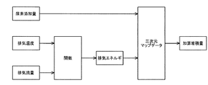
- FIG. 3 is a diagram illustrating the operation of the urea SCR system.
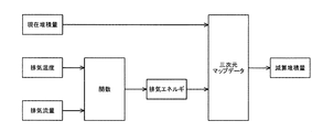
- FIG. 4 is a diagram illustrating the operation of the urea SCR system.
- the urea SCR system 100 includes a urea water injector 101, an SCR catalyst 102, and a control device 103.
- the urea water injector 101 adds urea water to the exhaust gas passing through the exhaust flow path 105 of the internal combustion engine 104.
- Ammonia is produced by hydrolyzing urea water in the exhaust gas with the heat of the exhaust gas, and a white product, which is an intermediate product, is produced in the process of producing ammonia. Since the white product is produced from the urea water in the exhaust gas, it is deposited in the exhaust flow path 105 located in the vicinity of the urea water injector 101 in which the urea water is present in the exhaust gas. Further, the urea water injector 101 is controlled by the control device 103, and the amount of urea water added by the urea water injector 101 is instructed by the control device 103.
- the urea water in the exhaust is efficiently hydrolyzed, and the temperature of the SCR catalyst 102 is efficiently set to the catalyst activation temperature on the upstream side of the exhaust of the urea water injector 101.
- An exhaust temperature raising device 106 for raising the temperature of the exhaust is installed.
- the exhaust gas heating device 106 is, for example, an oxidation catalyst.
- a first exhaust temperature sensor 107 that detects the exhaust temperature on the exhaust upstream side of the urea water injector 101 is installed on the exhaust upstream side of the urea water injector 101, and urea is installed on the exhaust downstream side of the urea water injector 101.
- a second exhaust temperature sensor 108 that detects the temperature of the exhaust gas is installed on the downstream side of the exhaust gas of the water injector 101. The exhaust temperature detected by the first exhaust temperature sensor 107 and the second exhaust temperature sensor 108 is input to the control device 103.
- the SCR catalyst 102 is installed on the downstream side of the exhaust of the urea water injector 101, and reduces nitrogen oxides to nitrogen and water by chemically reacting ammonia generated from urea water in the exhaust with nitrogen oxides in the exhaust. Is what you do.
- a nitrogen oxide concentration sensor 109 on the upstream side of the exhaust that detects the concentration of nitrogen oxides in the exhaust is installed.
- the nitrogen oxide concentration detected by the exhaust upstream nitrogen oxide concentration sensor 109 is input to the control device 103, and the control device 103 determines the nitrogen oxide concentration detected by the exhaust upstream nitrogen oxide concentration sensor 109. Based on this, the basic addition amount (feed forward value) of urea water is set.
- a nitrogen oxide concentration sensor 110 on the downstream side of the exhaust that detects the concentration of nitrogen oxides in the exhaust is installed.
- the nitrogen oxide concentration detected by the exhaust downstream nitrogen oxide concentration sensor 110 is input to the control device 103, and the control device 103 determines the nitrogen oxide concentration detected by the exhaust downstream nitrogen oxide concentration sensor 110. Based on this, the correction addition amount (feedback value) of urea water is set.
- the amount of urea water added by the urea water injector 101 is the amount of nitrogen oxides detected by the control device 103 and the nitrogen oxide concentration sensor 109 on the upstream side of the exhaust in order to purify the nitrogen oxides in the exhaust in just proportion.
- the optimum amount is adjusted based on the concentration and the concentration of nitrogen oxides detected by the nitrogen oxide concentration sensor 110 on the downstream side of the exhaust.
- a third exhaust temperature sensor 111 that detects the exhaust temperature on the exhaust downstream side of the SCR catalyst 102 is installed.
- the exhaust temperature detected by the third exhaust temperature sensor 111 is input to the control device 103, and the exhaust temperature detected by the third exhaust temperature sensor 111 is, for example, to grasp the internal temperature distribution of the SCR catalyst 102. It is used together with the exhaust temperature detected by the second exhaust temperature sensor 108.
- a mixing chamber 112 for stirring the urea water in the exhaust is installed between the urea water injector 101 and the SCR catalyst 102 in order to promote mixing of the urea water and the exhaust.
- the control device 103 estimates the amount of white products produced from the urea water in the exhaust in the exhaust flow path 105, and estimates the amount of white products accumulated in the exhaust flow path 105. It is instructed to carry out purging based on the amount of accumulated product in the exhaust flow path 105. For example, when the amount of the white product deposited in the exhaust flow path 105 is equal to or greater than the threshold value, a purge is instructed. In the purge, the control device 103 controls the internal combustion engine 104 and various devices included in the internal combustion engine 104, and raises the temperature of the exhaust gas to sublimate the white product.
- the control device 103 determines the additional accumulation amount (minimum value is zero) of the white product in the exhaust flow path 105 based on the amount of urea water added, the temperature of the exhaust gas, and the flow rate of the exhaust gas. .. Since the amount of urea water added is an indicated value when the control device 103 controls the urea water injector 101, it is naturally grasped by the control device 103.
- the exhaust temperature is the temperature of the exhaust at a position where the white product is likely to accumulate, for example, the temperature of the exhaust detected by the second exhaust temperature sensor 108, and is input to the control device 103.
- the exhaust flow rate is estimated by the control device 103 based on the operating state of the internal combustion engine 104, or the intake flow rate detected by the MAF (Mass Air Flow) sensor (not shown) and the fuel injector (not shown) in the control device 103. It is determined based on the fuel injection amount, which is an indicated value when controlling.
- MAF Mass Air Flow
- the control device 103 determines the exhaust energy based on the exhaust temperature and the exhaust flow rate, and the exhaust flow path of the white product based on the amount of urea water added and the exhaust energy.
- the additional deposition amount at 105 is determined.
- Exhaust energy is expressed by a function whose variables are the temperature of the exhaust and the flow rate of the exhaust.
- the control device 103 increases the additional accumulation amount of the white product in the exhaust flow path 105 as the amount of urea water added is larger and the exhaust energy is smaller.
- the reason why the additional accumulation amount of the white product in the exhaust flow path 105 increases as the amount of urea water added increases is because the amount of white product produced increases as the amount of urea water added increases. This is because it is considered that the amount of accumulated product in the exhaust flow path 105 increases.
- the reason why the additional accumulation amount of the white product in the exhaust flow path 105 increases as the exhaust energy is small is that when the exhaust energy is small, the white product is less likely to be sublimated and the white product is exhausted. This is because it is considered that it is likely to be deposited in the flow path 105.
- control device 103 determines the subtraction accumulation amount (maximum) of the white product in the exhaust flow path 105 based on the current accumulation amount in the exhaust flow path 105 of the white product, the temperature of the exhaust gas, and the flow rate of the exhaust gas. The value is zero).
- the accumulated amount of the white product in the exhaust flow path 105 is reset to zero at the time of product shipment or replacement with a new product, and is periodically integrated by the control device 103.
- the control device 103 determines the exhaust energy based on the exhaust temperature and the exhaust flow rate, and determines the current accumulated amount of the white product in the exhaust flow path 105 and the exhaust energy.
- the amount of subtraction deposition in the exhaust flow path 105 of the white product is determined based on the above.
- the control device 103 reduces the subtractive accumulation amount of the white product in the exhaust flow path 105 as the current accumulation amount in the exhaust flow path 105 of the white product increases and the exhaust energy decreases. Let me.
- the reason for reducing the subtractive deposition amount in the white product exhaust flow path 105 as the current accumulation amount in the white product exhaust flow path 105 increases is in the white product exhaust flow path 105. If the current amount of deposit is large, the cross-sectional area of the exhaust flow path 105 is greatly reduced, and the surface area of the white product exposed to the exhaust is also reduced, so that the white product is less likely to be sublimated and the white product is exhausted. This is because it is considered that the amount of deposit in the flow path 105 is unlikely to decrease.
- the reason why the amount of subtraction accumulation in the exhaust flow path 105 of the white product is reduced as the exhaust energy is small is that the white product is difficult to sublimate when the exhaust energy is small, so that the white product is exhausted. This is because it is considered that the amount of deposit in the flow path 105 is unlikely to decrease.
- the control device 103 sets the current deposition amount in the exhaust flow path 105 of the white product, the additional deposition amount in the exhaust flow path 105 of the white product, and the white product.
- the sum of the subtracted deposition amount in the exhaust flow path 105 is taken as the new deposition amount in the exhaust flow path 105 of the white product. Since the accumulation amount in the exhaust flow path 105 of the white product is updated, the new accumulation amount in the exhaust flow path 105 of the white product estimates the accumulation amount in the exhaust flow path 105 of the white product. In the next cycle, the amount of white product deposited in the exhaust flow path 105 will be the current amount.
- control device 103 notifies when the accumulated amount of the white product in the exhaust flow path 105 is equal to or more than the threshold value. Specifically, the operator who operates the internal combustion engine 104, the manager who manages the internal combustion engine 104, and / or the operator who maintains the internal combustion engine 104 is notified. Notifications may be made remotely via the Internet.
- the urea SCR system 100 capable of estimating the accumulated amount of the white product in the exhaust flow path 105 with high accuracy, the control device 103 of the urea SCR system 100, and the white product. It is possible to provide a method for estimating the amount of deposit.
- urea SCR system capable of estimating the accumulated amount of white products in the exhaust flow path with high accuracy, a control device for the urea SCR system, and a method of estimating the accumulated amount of white products.
Landscapes
- Engineering & Computer Science (AREA)
- Chemical & Material Sciences (AREA)
- Combustion & Propulsion (AREA)
- Analytical Chemistry (AREA)
- Biomedical Technology (AREA)
- Environmental & Geological Engineering (AREA)
- Health & Medical Sciences (AREA)
- General Chemical & Material Sciences (AREA)
- Oil, Petroleum & Natural Gas (AREA)
- Chemical Kinetics & Catalysis (AREA)
- Mechanical Engineering (AREA)
- General Engineering & Computer Science (AREA)
- Exhaust Gas After Treatment (AREA)
- Exhaust Gas Treatment By Means Of Catalyst (AREA)
Abstract
尿素水インジェクタ101と、SCR触媒102と、制御装置103と、を備え、制御装置103は、尿素水の添加量と排気の温度と排気の流量とを基に白色生成物の排気流路105に於ける加算堆積量を決定し、白色生成物の排気流路105に於ける現在の堆積量と排気の温度と排気の流量とを基に白色生成物の排気流路105に於ける減算堆積量を決定し、白色生成物の排気流路105に於ける現在の堆積量と白色生成物の排気流路105に於ける加算堆積量と白色生成物の排気流路105に於ける減算堆積量との和を白色生成物の排気流路105に於ける新規の堆積量とする尿素SCRシステム100によって課題を解決する事が出来る。
Description
尿素SCRシステム、尿素SCRシステムの制御装置、及び白色生成物の堆積量の推定方法に関する。
内燃機関の排気を浄化する尿素SCR(Selective Catalytic Reduction)システムは、尿素水インジェクタで、尿素水を排気中に添加し、尿素水インジェクタの排気下流側に設置されたSCR触媒により、排気中の尿素水から生成されたアンモニアを排気中の窒素酸化物と化学反応させる事で窒素酸化物を窒素と水とに還元するものである。
尿素SCRシステムでは、排気中の尿素水が排気の熱で加水分解される事でアンモニアに変化するが、排気の温度が低い場合や排気の流量が少ない場合は、排気中の尿素水がアンモニアに変化する過程で生成された白色生成物が昇華され難いので、排気流路に白色生成物が堆積する虞が有る。
排気流路に白色生成物が堆積すると、排気流路の断面積が減少したり、排気流路に設置されたセンサが埋没したりするので、内燃機関の性能への悪影響や触媒機能の低下が懸念される。
白色生成物の排気流路に於ける堆積量の推定に関して、従来の技術には改良の余地があった。
以上の事情に鑑み、白色生成物の排気流路に於ける堆積量を高精度に推定する事が可能な尿素SCRシステム、尿素SCRシステムの制御装置、及び白色生成物の堆積量の推定方法を提供する事を目的とする。
内燃機関の排気流路を通る排気中に尿素水を添加する尿素水インジェクタと、前記尿素水インジェクタの排気下流側に設置され、前記排気中の前記尿素水から生成されたアンモニアを前記排気中の窒素酸化物と化学反応させる事で前記窒素酸化物を窒素と水とに還元するSCR触媒と、前記排気中の前記尿素水から生成された白色生成物の前記排気流路に於ける堆積量を推定し、前記白色生成物の前記排気流路に於ける堆積量を基準にパージの実施を指示する制御装置と、を備える尿素SCRシステムであって、前記制御装置は、前記尿素水の添加量と前記排気の温度と前記排気の流量とを基に前記白色生成物の前記排気流路に於ける加算堆積量を決定し、前記白色生成物の前記排気流路に於ける現在の堆積量と前記排気の温度と前記排気の流量とを基に前記白色生成物の前記排気流路に於ける減算堆積量を決定し、前記白色生成物の前記排気流路に於ける現在の堆積量と前記白色生成物の前記排気流路に於ける加算堆積量と前記白色生成物の前記排気流路に於ける減算堆積量との和を前記白色生成物の前記排気流路に於ける新規の堆積量とする尿素SCRシステムを提供する。
前記制御装置は、前記排気の温度と前記排気の流量とを基に前記排気のエネルギを決定し、前記尿素水の添加量と前記排気のエネルギとを基に前記白色生成物の前記排気流路に於ける加算堆積量を決定する事が望ましい。
前記制御装置は、前記尿素水の添加量が多い程、及び前記排気のエネルギが小さい程、前記白色生成物の前記排気流路に於ける加算堆積量を増加させる事が望ましい。
前記制御装置は、前記排気の温度と前記排気の流量とを基に前記排気のエネルギを決定し、前記白色生成物の前記排気流路に於ける現在の堆積量と前記排気のエネルギとを基に前記白色生成物の前記排気流路に於ける減算堆積量を決定する事が望ましい。
前記制御装置は、前記白色生成物の前記排気流路に於ける現在の堆積量が多い程、及び前記排気のエネルギが小さい程、前記白色生成物の前記排気流路に於ける減算堆積量を減少させる事が望ましい。
前記制御装置は、前記白色生成物の前記排気流路に於ける堆積量が閾値以上である場合に通知する事が望ましい。
また、内燃機関の排気流路を通る排気中に尿素水を添加する尿素水インジェクタと、前記尿素水インジェクタの排気下流側に設置され、前記排気中の前記尿素水から生成されたアンモニアを前記排気中の窒素酸化物と化学反応させる事で前記窒素酸化物を窒素と水とに還元するSCR触媒と、を備える尿素SCRシステムを制御する制御装置であって、前記排気中の前記尿素水から生成された白色生成物の前記排気流路に於ける堆積量を推定し、前記白色生成物の前記排気流路に於ける堆積量を基準にパージの実施を指示すべく、前記尿素水の添加量と前記排気の温度と前記排気の流量とを基に前記白色生成物の前記排気流路に於ける加算堆積量を決定し、前記白色生成物の前記排気流路に於ける現在の堆積量と前記排気の温度と前記排気の流量とを基に前記白色生成物の前記排気流路に於ける減算堆積量を決定し、前記白色生成物の前記排気流路に於ける現在の堆積量と前記白色生成物の前記排気流路に於ける加算堆積量と前記白色生成物の前記排気流路に於ける減算堆積量との和を前記白色生成物の前記排気流路に於ける新規の堆積量とする制御装置を提供する。
更に、内燃機関の排気流路を通る排気中に尿素水を添加する尿素水インジェクタと、前記尿素水インジェクタの排気下流側に設置され、前記排気中の前記尿素水から生成されたアンモニアを前記排気中の窒素酸化物と化学反応させる事で前記窒素酸化物を窒素と水とに還元するSCR触媒と、を備える尿素SCRシステムで、前記排気中の前記尿素水から生成された白色生成物の前記排気流路に於ける堆積量を推定し、前記白色生成物の前記排気流路に於ける堆積量を基準にパージの実施を指示すべく、前記尿素水の添加量と前記排気の温度と前記排気の流量とを基に前記白色生成物の前記排気流路に於ける加算堆積量を決定し、前記白色生成物の前記排気流路に於ける現在の堆積量と前記排気の温度と前記排気の流量とを基に前記白色生成物の前記排気流路に於ける減算堆積量を決定し、前記白色生成物の前記排気流路に於ける現在の堆積量と前記白色生成物の前記排気流路に於ける加算堆積量と前記白色生成物の前記排気流路に於ける減算堆積量との和を前記白色生成物の前記排気流路に於ける新規の堆積量とする白色生成物の堆積量の推定方法を提供する。
白色生成物の排気流路に於ける堆積量を高精度に推定する事が可能な尿素SCRシステム、尿素SCRシステムの制御装置、及び白色生成物の堆積量の推定方法を提供する事が出来る。
図1に示す様に、尿素SCRシステム100は、尿素水インジェクタ101と、SCR触媒102と、制御装置103と、を備える。
尿素水インジェクタ101は、内燃機関104の排気流路105を通る排気中に尿素水を添加するものである。排気中の尿素水が排気の熱で加水分解される事でアンモニアが生成され、アンモニアが生成される過程で中間生成物である白色生成物が生成される。白色生成物は、排気中の尿素水から生成されるので、排気中に尿素水が存在する尿素水インジェクタ101の近傍に位置する排気流路105に於いて堆積する。また、尿素水インジェクタ101は、制御装置103により制御され、尿素水インジェクタ101による尿素水の添加量は、制御装置103により指示される。
尿素水インジェクタ101の排気上流側には、排気中の尿素水を効率的に加水分解させ、SCR触媒102の温度を効率的に触媒活性化温度とすべく、尿素水インジェクタ101の排気上流側で排気の温度を昇温させる排気昇温装置106が設置される。排気昇温装置106は、例えば、酸化触媒である。
また、尿素水インジェクタ101の排気上流側には、尿素水インジェクタ101の排気上流側で排気の温度を検出する第一排気温度センサ107が設置され、尿素水インジェクタ101の排気下流側には、尿素水インジェクタ101の排気下流側で排気の温度を検出する第二排気温度センサ108が設置される。第一排気温度センサ107や第二排気温度センサ108によって検出された排気の温度は制御装置103に入力される。
SCR触媒102は、尿素水インジェクタ101の排気下流側に設置され、排気中の尿素水から生成されたアンモニアを排気中の窒素酸化物と化学反応させる事で窒素酸化物を窒素と水とに還元するものである。
SCR触媒102の排気上流側には、排気中の窒素酸化物の濃度を検出する排気上流側窒素酸化物濃度センサ109が設置される。排気上流側窒素酸化物濃度センサ109によって検出された窒素酸化物の濃度は制御装置103に入力され、制御装置103により、排気上流側窒素酸化物濃度センサ109によって検出された窒素酸化物の濃度を基に尿素水の基本添加量(フィードフォワード値)が設定される。
SCR触媒102の排気下流側には、排気中の窒素酸化物の濃度を検出する排気下流側窒素酸化物濃度センサ110が設置される。排気下流側窒素酸化物濃度センサ110によって検出された窒素酸化物の濃度は制御装置103に入力され、制御装置103により、排気下流側窒素酸化物濃度センサ110によって検出された窒素酸化物の濃度を基に尿素水の補正添加量(フィードバック値)が設定される。
従って、尿素水インジェクタ101による尿素水の添加量は、排気中の窒素酸化物を過不足無く浄化すべく、制御装置103により、排気上流側窒素酸化物濃度センサ109によって検出された窒素酸化物の濃度と排気下流側窒素酸化物濃度センサ110によって検出された窒素酸化物の濃度とを基に最適な量に調整される。
また、SCR触媒102の排気下流側には、SCR触媒102の排気下流側で排気の温度を検出する第三排気温度センサ111が設置される。第三排気温度センサ111によって検出された排気の温度は制御装置103に入力され、第三排気温度センサ111によって検出された排気の温度は、例えば、SCR触媒102の内部温度分布を把握すべく、第二排気温度センサ108によって検出された排気の温度と共に使用される。
尿素水インジェクタ101とSCR触媒102との間には、尿素水と排気との混合を促進すべく、排気中の尿素水を攪拌するミキシングチャンバ112が設置される。
制御装置103は、内燃機関104や内燃機関104が有する各種装置を制御するのに加え、排気中の尿素水から生成された白色生成物の排気流路105に於ける堆積量を推定し、白色生成物の排気流路105に於ける堆積量を基準にパージの実施を指示するものである。例えば、白色生成物の排気流路105に於ける堆積量が閾値以上である場合にパージの実施を指示する。パージは、制御装置103により内燃機関104や内燃機関104が有する各種装置を制御し、排気の温度を昇温させる事で白色生成物を昇華させるものである。
具体的には、制御装置103は、尿素水の添加量と排気の温度と排気の流量とを基に白色生成物の排気流路105に於ける加算堆積量(最小値はゼロ)を決定する。尿素水の添加量は、制御装置103が尿素水インジェクタ101を制御する際の指示値であるので、制御装置103によって当然に把握される。排気の温度は、白色生成物が堆積し易い位置の排気の温度であって、例えば、第二排気温度センサ108によって検出された排気の温度であり、制御装置103に入力される。排気の流量は、制御装置103によって内燃機関104の運転状態を基に推定されるか、不図示のMAF(Mass Air Flow)センサによって検出された吸気の流量と制御装置103が不図示の燃料インジェクタを制御する際の指示値である燃料の噴射量とを基に決定される。
図2に示す様に、制御装置103は、排気の温度と排気の流量とを基に排気のエネルギを決定し、尿素水の添加量と排気のエネルギとを基に白色生成物の排気流路105に於ける加算堆積量を決定する。排気のエネルギは、排気の温度と排気の流量とを変数とする関数によって表される。尿素水の添加量と排気のエネルギとを基に白色生成物の排気流路105に於ける加算堆積量を決定する際は、予め実験を経て作成された三次元マップデータを参照する事で決定する。
尚、制御装置103は、尿素水の添加量が多い程、及び排気のエネルギが小さい程、白色生成物の排気流路105に於ける加算堆積量を増加させる。尿素水の添加量が多い程、白色生成物の排気流路105に於ける加算堆積量を増加させる理由は、尿素水の添加量が多いと、白色生成物の生成量も多くなるので、白色生成物の排気流路105に於ける堆積量が増加すると考えられるからである。また、排気のエネルギが小さい程、白色生成物の排気流路105に於ける加算堆積量を増加させる理由は、排気のエネルギが小さいと、白色生成物が昇華され難くなり、白色生成物が排気流路105に堆積し易くなると考えられるからである。
また、制御装置103は、白色生成物の排気流路105に於ける現在の堆積量と排気の温度と排気の流量とを基に白色生成物の排気流路105に於ける減算堆積量(最大値はゼロ)を決定する。白色生成物の排気流路105に於ける堆積量は、製品出荷時や新品交換時にゼロリセットされ、制御装置103によって周期的に積算される。
図3に示す様に、制御装置103は、排気の温度と排気の流量とを基に排気のエネルギを決定し、白色生成物の排気流路105に於ける現在の堆積量と排気のエネルギとを基に白色生成物の排気流路105に於ける減算堆積量を決定する。白色生成物の排気流路105に於ける現在の堆積量と排気のエネルギとを基に白色生成物の排気流路105に於ける減算堆積量を決定する際は、予め実験を経て作成された三次元マップデータを参照する事で決定する。
尚、制御装置103は、白色生成物の排気流路105に於ける現在の堆積量が多い程、及び排気のエネルギが小さい程、白色生成物の排気流路105に於ける減算堆積量を減少させる。白色生成物の排気流路105に於ける現在の堆積量が多い程、白色生成物の排気流路105に於ける減算堆積量を減少させる理由は、白色生成物の排気流路105に於ける現在の堆積量が多いと、排気流路105の断面積の減少が大きくなり、排気に曝露される白色生成物の表面積も減少するので、白色生成物が昇華され難くなり、白色生成物の排気流路105に於ける堆積量が減少し難くなると考えられるからである。また、排気のエネルギが小さい程、白色生成物の排気流路105に於ける減算堆積量を減少させる理由は、排気のエネルギが小さいと、白色生成物が昇華され難いので、白色生成物の排気流路105に於ける堆積量が減少し難くなると考えられるからである。
図4に示す様に、制御装置103は、しかる後、白色生成物の排気流路105に於ける現在の堆積量と白色生成物の排気流路105に於ける加算堆積量と白色生成物の排気流路105に於ける減算堆積量との和を白色生成物の排気流路105に於ける新規の堆積量とする。白色生成物の排気流路105に於ける堆積量を更新するので、白色生成物の排気流路105に於ける新規の堆積量は、白色生成物の排気流路105に於ける堆積量を推定する次の周期では、白色生成物の排気流路105に於ける現在の堆積量となる。
更に、制御装置103は、白色生成物の排気流路105に於ける堆積量が閾値以上である場合に通知する。具体的には、内燃機関104を操作する操作者、内燃機関104を管理する管理者、及び/又は内燃機関104を整備する作業者に通知する。通知は、インターネットを通じて遠隔で行われても良い。
以上に説明された様に、白色生成物の排気流路105に於ける堆積量を高精度に推定する事が可能な尿素SCRシステム100、尿素SCRシステム100の制御装置103、及び白色生成物の堆積量の推定方法を提供する事が出来る。
本出願は、2020年3月19日付で出願された日本国特許出願(特願2020-049749)に基づくものであり、その内容はここに参照として取り込まれる。
白色生成物の排気流路に於ける堆積量を高精度に推定する事が可能な尿素SCRシステム、尿素SCRシステムの制御装置、及び白色生成物の堆積量の推定方法を提供する事が出来る。
100 尿素SCRシステム
101 尿素水インジェクタ
102 SCR触媒
103 制御装置
104 内燃機関
105 排気流路
106 排気昇温装置
107 第一排気温度センサ
108 第二排気温度センサ
109 排気上流側窒素酸化物濃度センサ
110 排気下流側窒素酸化物濃度センサ
111 第三排気温度センサ
112 ミキシングチャンバ
101 尿素水インジェクタ
102 SCR触媒
103 制御装置
104 内燃機関
105 排気流路
106 排気昇温装置
107 第一排気温度センサ
108 第二排気温度センサ
109 排気上流側窒素酸化物濃度センサ
110 排気下流側窒素酸化物濃度センサ
111 第三排気温度センサ
112 ミキシングチャンバ
Claims (8)
- 内燃機関の排気流路を通る排気中に尿素水を添加する尿素水インジェクタと、
前記尿素水インジェクタの排気下流側に設置され、前記排気中の前記尿素水から生成されたアンモニアを前記排気中の窒素酸化物と化学反応させる事で前記窒素酸化物を窒素と水とに還元するSCR触媒と、
前記排気中の前記尿素水から生成された白色生成物の前記排気流路に於ける堆積量を推定し、前記白色生成物の前記排気流路に於ける堆積量を基準にパージの実施を指示する制御装置と、
を備える尿素SCRシステムであって、
前記制御装置は、前記尿素水の添加量と前記排気の温度と前記排気の流量とを基に前記白色生成物の前記排気流路に於ける加算堆積量を決定し、前記白色生成物の前記排気流路に於ける現在の堆積量と前記排気の温度と前記排気の流量とを基に前記白色生成物の前記排気流路に於ける減算堆積量を決定し、前記白色生成物の前記排気流路に於ける現在の堆積量と前記白色生成物の前記排気流路に於ける加算堆積量と前記白色生成物の前記排気流路に於ける減算堆積量との和を前記白色生成物の前記排気流路に於ける新規の堆積量とする
事を特徴とする尿素SCRシステム。 - 前記制御装置は、前記排気の温度と前記排気の流量とを基に前記排気のエネルギを決定し、前記尿素水の添加量と前記排気のエネルギとを基に前記白色生成物の前記排気流路に於ける加算堆積量を決定する
請求項1に記載の尿素SCRシステム。 - 前記制御装置は、前記尿素水の添加量が多い程、及び前記排気のエネルギが小さい程、前記白色生成物の前記排気流路に於ける加算堆積量を増加させる
請求項2に記載の尿素SCRシステム。 - 前記制御装置は、前記排気の温度と前記排気の流量とを基に前記排気のエネルギを決定し、前記白色生成物の前記排気流路に於ける現在の堆積量と前記排気のエネルギとを基に前記白色生成物の前記排気流路に於ける減算堆積量を決定する
請求項1乃至3の何れか一項に記載の尿素SCRシステム。 - 前記制御装置は、前記白色生成物の前記排気流路に於ける現在の堆積量が多い程、及び前記排気のエネルギが小さい程、前記白色生成物の前記排気流路に於ける減算堆積量を減少させる
請求項4に記載の尿素SCRシステム。 - 前記制御装置は、前記白色生成物の前記排気流路に於ける堆積量が閾値以上である場合に通知する
請求項1乃至5の何れか一項に記載の尿素SCRシステム。 - 内燃機関の排気流路を通る排気中に尿素水を添加する尿素水インジェクタと、前記尿素水インジェクタの排気下流側に設置され、前記排気中の前記尿素水から生成されたアンモニアを前記排気中の窒素酸化物と化学反応させる事で前記窒素酸化物を窒素と水とに還元するSCR触媒と、を備える尿素SCRシステムを制御する制御装置であって、
前記制御装置は、前記排気中の前記尿素水から生成された白色生成物の前記排気流路に於ける堆積量を推定し、前記白色生成物の前記排気流路に於ける堆積量を基準にパージの実施を指示すべく、前記尿素水の添加量と前記排気の温度と前記排気の流量とを基に前記白色生成物の前記排気流路に於ける加算堆積量を決定し、前記白色生成物の前記排気流路に於ける現在の堆積量と前記排気の温度と前記排気の流量とを基に前記白色生成物の前記排気流路に於ける減算堆積量を決定し、前記白色生成物の前記排気流路に於ける現在の堆積量と前記白色生成物の前記排気流路に於ける加算堆積量と前記白色生成物の前記排気流路に於ける減算堆積量との和を前記白色生成物の前記排気流路に於ける新規の堆積量とする
事を特徴とする制御装置。 - 内燃機関の排気流路を通る排気中に尿素水を添加する尿素水インジェクタと、前記尿素水インジェクタの排気下流側に設置され、前記排気中の前記尿素水から生成されたアンモニアを前記排気中の窒素酸化物と化学反応させる事で前記窒素酸化物を窒素と水とに還元するSCR触媒と、を備える尿素SCRシステムで、前記排気中の前記尿素水から生成された白色生成物の前記排気流路に於ける堆積量を推定し、前記白色生成物の前記排気流路に於ける堆積量を基準にパージの実施を指示すべく、前記尿素水の添加量と前記排気の温度と前記排気の流量とを基に前記白色生成物の前記排気流路に於ける加算堆積量を決定し、前記白色生成物の前記排気流路に於ける現在の堆積量と前記排気の温度と前記排気の流量とを基に前記白色生成物の前記排気流路に於ける減算堆積量を決定し、前記白色生成物の前記排気流路に於ける現在の堆積量と前記白色生成物の前記排気流路に於ける加算堆積量と前記白色生成物の前記排気流路に於ける減算堆積量との和を前記白色生成物の前記排気流路に於ける新規の堆積量とする
事を特徴とする白色生成物の堆積量の推定方法。
Priority Applications (1)
| Application Number | Priority Date | Filing Date | Title |
|---|---|---|---|
| CN202180022461.7A CN115315570B (zh) | 2020-03-19 | 2021-03-15 | 尿素scr系统、尿素scr系统的控制装置、及白色生成物的堆积量的推定方法 |
Applications Claiming Priority (2)
| Application Number | Priority Date | Filing Date | Title |
|---|---|---|---|
| JP2020049749A JP7322769B2 (ja) | 2020-03-19 | 2020-03-19 | 尿素scrシステム、尿素scrシステムの制御装置、及び白色生成物の堆積量の推定方法 |
| JP2020-049749 | 2020-03-19 |
Publications (1)
| Publication Number | Publication Date |
|---|---|
| WO2021187439A1 true WO2021187439A1 (ja) | 2021-09-23 |
Family
ID=77770963
Family Applications (1)
| Application Number | Title | Priority Date | Filing Date |
|---|---|---|---|
| PCT/JP2021/010434 Ceased WO2021187439A1 (ja) | 2020-03-19 | 2021-03-15 | 尿素scrシステム、尿素scrシステムの制御装置、及び白色生成物の堆積量の推定方法 |
Country Status (3)
| Country | Link |
|---|---|
| JP (1) | JP7322769B2 (ja) |
| CN (1) | CN115315570B (ja) |
| WO (1) | WO2021187439A1 (ja) |
Cited By (1)
| Publication number | Priority date | Publication date | Assignee | Title |
|---|---|---|---|---|
| US11946401B2 (en) * | 2021-10-19 | 2024-04-02 | Volvo Penta Corporation | Method for predicting urea crystal build-up in an engine system |
Families Citing this family (1)
| Publication number | Priority date | Publication date | Assignee | Title |
|---|---|---|---|---|
| JP2023040894A (ja) | 2021-09-10 | 2023-03-23 | 株式会社東海理化電機製作所 | 操作装置 |
Citations (4)
| Publication number | Priority date | Publication date | Assignee | Title |
|---|---|---|---|---|
| JP2009257190A (ja) * | 2008-04-16 | 2009-11-05 | Mitsubishi Fuso Truck & Bus Corp | 排気浄化装置 |
| JP2011220232A (ja) * | 2010-04-09 | 2011-11-04 | Ud Trucks Corp | エンジンの排気浄化装置 |
| JP2015010508A (ja) * | 2013-06-27 | 2015-01-19 | 株式会社日本自動車部品総合研究所 | 内燃機関の排気浄化装置 |
| US20190063289A1 (en) * | 2017-08-29 | 2019-02-28 | Caterpillar Inc. | Method and system for modeling reductant deposit growth |
-
2020
- 2020-03-19 JP JP2020049749A patent/JP7322769B2/ja active Active
-
2021
- 2021-03-15 CN CN202180022461.7A patent/CN115315570B/zh active Active
- 2021-03-15 WO PCT/JP2021/010434 patent/WO2021187439A1/ja not_active Ceased
Patent Citations (4)
| Publication number | Priority date | Publication date | Assignee | Title |
|---|---|---|---|---|
| JP2009257190A (ja) * | 2008-04-16 | 2009-11-05 | Mitsubishi Fuso Truck & Bus Corp | 排気浄化装置 |
| JP2011220232A (ja) * | 2010-04-09 | 2011-11-04 | Ud Trucks Corp | エンジンの排気浄化装置 |
| JP2015010508A (ja) * | 2013-06-27 | 2015-01-19 | 株式会社日本自動車部品総合研究所 | 内燃機関の排気浄化装置 |
| US20190063289A1 (en) * | 2017-08-29 | 2019-02-28 | Caterpillar Inc. | Method and system for modeling reductant deposit growth |
Cited By (1)
| Publication number | Priority date | Publication date | Assignee | Title |
|---|---|---|---|---|
| US11946401B2 (en) * | 2021-10-19 | 2024-04-02 | Volvo Penta Corporation | Method for predicting urea crystal build-up in an engine system |
Also Published As
| Publication number | Publication date |
|---|---|
| JP2021148085A (ja) | 2021-09-27 |
| CN115315570B (zh) | 2024-04-05 |
| JP7322769B2 (ja) | 2023-08-08 |
| CN115315570A (zh) | 2022-11-08 |
Similar Documents
| Publication | Publication Date | Title |
|---|---|---|
| JP5096665B2 (ja) | 内燃機関の排気ガスを浄化するために使用される触媒の作動方法およびその方法を実施する装置 | |
| EP2047088A2 (en) | Control of selective catalytic reduction | |
| CN101713320B (zh) | 微粒过滤器再生时优化车辆中排气温度控制的设备和方法 | |
| EP3660288A1 (en) | Injection amount control method and device for scr urea injection system in engine | |
| US20080271437A1 (en) | Atmospheric temperature detecting apparatus and exhaust emission purification apparatus | |
| WO2011118095A1 (ja) | エンジンの排気浄化装置及びエンジンの排気浄化方法 | |
| JP4290081B2 (ja) | 排気浄化装置 | |
| EP2319608B1 (en) | Exhaust gas purification apparatus for internal combustion engine | |
| NL8403184A (nl) | Werkwijze voor het regelen van de hoeveelheid toe te voeren reductiemiddel bij de katalytische reductie van no in rookgassen. | |
| WO2011108110A1 (ja) | 内燃機関の排気浄化装置 | |
| JP2017120081A (ja) | ディーゼルエンジンの排気処理装置 | |
| JP7322769B2 (ja) | 尿素scrシステム、尿素scrシステムの制御装置、及び白色生成物の堆積量の推定方法 | |
| WO2011125258A1 (ja) | エンジンの排気浄化装置 | |
| WO2014097391A1 (ja) | 内燃機関の排気浄化システム | |
| JP5560089B2 (ja) | 内燃機関の排気浄化装置 | |
| JP3979150B2 (ja) | 内燃機関のNOx浄化装置 | |
| JP5837312B2 (ja) | 内燃機関の排気浄化システム | |
| JP2008163856A (ja) | 内燃機関の排気浄化装置 | |
| JP5610956B2 (ja) | 排ガス浄化装置の制御方法および制御装置 | |
| JP5570188B2 (ja) | エンジンの排気浄化装置 | |
| JP2021148004A (ja) | 排気浄化装置、及び車両 | |
| JP2015194120A (ja) | 排気ガス浄化装置 | |
| JP7238808B2 (ja) | 尿素scrシステム | |
| JP2015190381A (ja) | 排気ガス浄化装置 | |
| JP6032985B2 (ja) | 還元剤注入装置及び脱硝装置 |
Legal Events
| Date | Code | Title | Description |
|---|---|---|---|
| 121 | Ep: the epo has been informed by wipo that ep was designated in this application |
Ref document number: 21772056 Country of ref document: EP Kind code of ref document: A1 |
|
| NENP | Non-entry into the national phase |
Ref country code: DE |
|
| 122 | Ep: pct application non-entry in european phase |
Ref document number: 21772056 Country of ref document: EP Kind code of ref document: A1 |