WO2021187400A1 - モータ用バスバー - Google Patents
モータ用バスバー Download PDFInfo
- Publication number
- WO2021187400A1 WO2021187400A1 PCT/JP2021/010291 JP2021010291W WO2021187400A1 WO 2021187400 A1 WO2021187400 A1 WO 2021187400A1 JP 2021010291 W JP2021010291 W JP 2021010291W WO 2021187400 A1 WO2021187400 A1 WO 2021187400A1
- Authority
- WO
- WIPO (PCT)
- Prior art keywords
- side portion
- bus bar
- motor
- winding
- terminal
- Prior art date
- Legal status (The legal status is an assumption and is not a legal conclusion. Google has not performed a legal analysis and makes no representation as to the accuracy of the status listed.)
- Ceased
Links
Images




Classifications
-
- H—ELECTRICITY
- H02—GENERATION; CONVERSION OR DISTRIBUTION OF ELECTRIC POWER
- H02K—DYNAMO-ELECTRIC MACHINES
- H02K3/00—Details of windings
- H02K3/04—Windings characterised by the conductor shape, form or construction, e.g. with bar conductors
Definitions
- This disclosure relates to a bus bar for a motor used for a motor.
- Patent Document 1 describes a bus bar that includes a terminal side portion that extends parallel to the central axis of the motor and a winding side portion that extends around the central axis, and is integrally formed of a conductive material that is the same material as a whole. Has been done.
- An object of the present disclosure is to provide a bus bar for a motor, which has a low resistance loss as a whole and can be manufactured with a high yield.
- the bus bar for a motor of the present disclosure joins a winding side portion electrically connected to the winding of a motor, a terminal side portion having a terminal portion connected to an external device, and a winding side portion and a terminal side portion.
- the winding side portion and the terminal side portion are made of conductive materials having different electrical resistances.
- the bus bar for a motor of the present disclosure since the winding side portion and the terminal side portion are formed of conductive materials having different electrical resistivitys, the resistance loss of the entire bus bar can be reduced and heat generation can be suppressed. Further, the winding side portion and the terminal side portion can be processed separately to suppress material loss, and the bus bar can be manufactured with a good yield.
- FIG. 1 is a cross-sectional view of a motor showing an embodiment.
- FIG. 2 is a cross-sectional view taken along the line II-II of FIG.
- FIG. 3 is a perspective view of the bus bar holder, terminal holder and end frame.
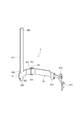
- FIG. 4 is a perspective view showing an embodiment of the bus bar.
- FIG. 5 is a developed view showing a punched shape of a winding side portion and a terminal side portion according to one embodiment.
- FIG. 6 is a developed view showing a punched shape of the integrated bus bar of the comparative example.
- the motor 1 shown in FIG. 1 is a three-phase brushless motor used in a system for generating brake hydraulic pressure of a vehicle, and is an end frame 22 in which a motor housing 2 covers a main body 21 with a bottom and an upper end opening portion 211 of the main body 21. It consists of.
- a stator 3 and a rotor 4 are housed inside the main body 21, and a three-phase winding 5 is wound around a plurality of teeth (not shown) of the stator 3.
- the end portion 51 of each winding 5 is electrically connected to the connector 7 of the external device (hereinafter referred to as the external connector 7) via a separate bus bar 6.
- a shaft 8 is fixed to the rotor 4, the upper end of the shaft 8 is supported by the upper bearing 9 on the end frame 22, and the lower end of the shaft 8 is supported by the lower bearing 11 on the bottom wall portion 212 of the housing body 21. Then, when power is supplied from the external connector 7 to the winding 5, the shaft 8 is rotated around the central axis O together with the rotor 4 by the rotating magnetic field formed between the stator 3 and the rotor 4. ..
- the direction in which the bus bar 6 protrudes is referred to as "upper" of the motor 1, and the opposite side is referred to as "lower".
- a bus bar holder 14 for holding the three-phase bus bar 6 is installed on the stator 3.
- the bus bar holder 14 includes an annular portion 141 made of an insulating material such as resin, and an opening 142 into which the body portion 221 of the end frame 22 is fitted is formed in the center of the annular portion 141. Further, the ring portion 141 is hooked on a plurality of notch portions 143 into which the end portion 51 of the winding 5 is inserted, a plurality of positioning portions 144 composed of protrusions or holes for positioning the bus bar 6, and a stator 3. A plurality of hook pieces 145 are formed.
- a terminal holder 15 for holding the terminal portion 623 of the three-phase bus bar 6 is mounted on the end frame 22.
- the terminal holder 15 includes a disk portion 151 that covers the flange portion 222 of the end frame 22, and a cylindrical portion 152 that is fitted from the inside to the body portion 221 of the end frame 22, and is entirely ringed with an insulating material such as resin. It is formed in a shape.
- a sleeve 153 is erected on the disk portion 151, and a terminal side portion 62 of the bus bar 6 is held through the three through holes 154 of the sleeve 153.
- the flange portion 222 of the end frame 22 is formed with a slit 223 into which the bus bar 6 is fitted.
- FIG. 4 shows a bus bar arranged in the U portion of the three-phase bus bar 6 shown in FIG.
- the bus bar 6 is wound with a winding side portion 61 to which two windings 5 of one of the three phases corresponding to each other are connected, and a terminal side portion 62 having a terminal portion 623 connected to the external connector 7.
- a joining portion 63 for joining the wire side portion 61 and the terminal side portion 62 is provided.
- the entire bus bar 6 is formed in a substantially L shape. At the time of manufacture, the winding side portion 61 and the terminal side portion 62 are punched as separate parts, and the joint portion 63 of both parts is connected by welding.
- the winding side portion 61 and the terminal side portion 62 are made of conductive materials having different electrical resistivitys.
- the winding side portion 61 is formed of a first conductive material having a relatively low electrical resistivity
- the terminal side portion 62 is formed of a second conductive material having a relatively high electrical resistivity.
- the first conductive material pure copper, which is substantially the same material as the winding 5 to which the winding side portion 61 is connected, is used.
- the second conductive material brass, which is substantially the same material as the terminal material of the external connector 7 to which the terminal side portion 62 is connected, is used.
- the winding side portion 61 is formed in a horizontally long shape extending around the central axis O of the motor 1, and the terminal side portion 62 is joined to one end of the winding side portion 61.
- a side joint 611 is provided.
- two connection pieces 612 are formed to which the ends 51 (see FIG. 1) of the two windings 5 are separately connected.
- a winding side locking piece 613 that is locked to the positioning portion 144 of the bus bar holder 14 is formed between the connecting piece 612 and the winding side joint portion 611. Then, the winding side portion 61 is locked at a fixed position with respect to the stator 3 by the winding side locking piece 613 via the bus bar holder 14.
- the terminal side portion 62 is composed of a vertically long first piece 621 extending substantially parallel to the central axis O of the motor 1 and a second piece 622 extending around the central axis O, and a terminal portion 623 at the upper end of the first piece 621.
- the terminal side joint portion 624 is provided at the tip of the second piece 622.
- the winding side portion 61 extends in the extension direction of the second piece 622, and the winding side joint portion 611 is joined to the terminal side joint portion 624.
- the intersection 625 between the first piece 621 and the second piece 622 is provided with a terminal-side locking piece 626 that is locked in a locking hole (not shown) of the bus bar holder 14, and the terminal-side portion 62 is on the terminal side. It is locked in place with respect to the stator 3 via the bus bar holder 14 by the locking piece 626.
- the joint portion 63 of the bus bar 6 is formed so that the welded portion 631 straddles both the winding side joint portion 611 and the terminal side joint portion 624.
- the welded portion 631 shown in FIG. 4 is formed in a dot shape by spot welding, a linear welded portion may be formed along the peripheral edges of the winding side joint portion 611 and the terminal side joint portion 624.
- the two bus bars arranged other than the U portion were arranged outside the U portion, except that the lengths of 61 on the winding side portion differed. It is configured in substantially the same manner as the bus bar 6.
- the winding side portion 61 is made of pure copper having a lower electrical resistivity than the terminal side portion 62, the resistance loss as a whole is reduced as compared with the case where the entire bus bar 6 is made of brass. It can be reduced and heat generation can be suppressed.
- the winding side portion 61 and the terminal side portion 62 are punched out from the respective conductive plates by a press, and the welded portion 631 is formed at the joint portion 63.
- the welded portion 631 firmly joins two parts made of different materials, secures a sufficient welding area at the joined portion 63, and reduces resistance loss. Further, as shown in FIG. 5, parts can be punched out from the rectangular material 601 for the winding side portion 61 and the rectangular material 602 for the terminal side portion 62, respectively. Therefore, the material loss due to the punching process can be reduced, and the bus bar 6 can be manufactured with a high yield.
- FIG. 6 shows a punched shape of the bus bar 70 in which the winding side portion 71 and the terminal side portion 72 are integrated as a comparative example. Comparing FIGS. 5 and 6, it can be seen that the bus bar 6 according to the present embodiment has less material loss during production than the bus bar 70 of the comparative example. Further, in the bus bar 6 of the present embodiment, since the terminal side portion 62 is made of brass, the material cost of the bus bar 6 as a whole can be reduced.
- the electrical resistivity of the winding side portion 61 is set lower than the electrical resistivity of the terminal side portion 62, but in other embodiments, the electrical resistivity of the terminal side portion is wound. It is also possible to set it lower than the electrical resistivity of the wire side portion. By doing so, it is possible to reduce the resistance loss of the terminal side portion in the application where it is necessary to protect the external device from heat generation.
- the winding side locking piece 613 and the terminal side locking piece 626 hold the bus bar holder 14 in order to lock the winding side portion 61 and the terminal side portion 62 to the fixed positions of the stator 3.
- it is indirectly locked to the stator 3 via in other embodiments, it is also possible to provide the winding side locking piece and the terminal side locking piece so that they can be directly locked to the stator 3. be.
- the joint portion 63 is arranged at a portion extending around the central axis O of the motor 1, but in other embodiments, the joint portion is arranged at a portion extending parallel to the central axis of the motor. It is also possible.
Landscapes
- Engineering & Computer Science (AREA)
- Power Engineering (AREA)
- Windings For Motors And Generators (AREA)
- Insulation, Fastening Of Motor, Generator Windings (AREA)
Abstract
モータ用バスバー(6)は、モータ(1)の巻線(5)に接続される巻線側部分(61)と、外部機器(7)に接続される端子部(623)を有する端子側部分(62)と、巻線側部分(61)および端子側部分(62)を接合する接合部分(63)と、を備える。巻線側部分(61)および端子側部分(62)は、異なる電気抵抗率の導電材料で形成されている。
Description
本出願は、2020年3月18日に出願された特許出願番号2020-047364号に基づくものであり、ここにその記載内容を援用する。
本開示は、モータに使用されるモータ用バスバーに関する。
従来、モータの巻線に接続される巻線側部分と、外部機器の端子が接続される端子側部分と、を備えたバスバーが知られている。例えば、特許文献1には、モータの中心軸と平行に延びる端子側部分と、中心軸の周囲を延びる巻線側部分とを備え、全体が同じ材質の導電材料で一体形成されたバスバーが記載されている。
ところが、バスバー全体を同じ材質の導電材料、例えば黄銅で形成すると、バスバー全体の抵抗損失が多く、発熱量が増加するという問題がある。また、中心軸と平行に延びる端子側部分と中心軸の周囲を延びる巻線側部分とを打ち抜き加工によって一体に形成すると、材料ロスが増加し、歩留まりが低下するという問題点があった。本開示の目的は、全体としての抵抗損失が少なく、かつ歩留まり良く製作できるモータ用バスバーを提供することにある。
本開示のモータ用バスバーは、モータの巻線に電気的に接続される巻線側部分と、外部機器に接続される端子部を有する端子側部分と、巻線側部分および端子側部分を接合する接合部分と、を備え、巻線側部分および端子側部分は、異なる電気抵抗率の導電材料で形成されている。
本開示のモータ用バスバーによれば、巻線側部分および端子側部分が異なる電気抵抗率の導電材料で形成されているので、バスバー全体としての抵抗損失を少なくし、発熱を抑えることができる。また、巻線側部分および端子側部分を別々に加工し、材料ロスを抑え、バスバーを歩留まり良く製作することができる。
本開示についての上記目的及びその他の目的、特徴や利点は、添付の図面を参照しながら下記の詳細な記述により、より明確になる。その図面は、
図1は、一実施形態を示すモータの断面図であり、
図2は、図1のII-II線断面図であり、
図3は、バスバーホルダ、ターミナルホルダおよびエンドフレームの斜視図であり、
図4は、バスバーの実施形態を示す斜視図であり、
図5は、一実施形態による巻線側部分および端子側部分の打ち抜き形状を示す展開図であり、
図6は、比較例の一体型バスバーの打ち抜き形状を示す展開図である。
<一実施形態>
以下、一実施形態のモータ用バスバーを図面に基づいて説明する。まず、本実施形態を適用したモータの構成について説明する。図1に示すモータ1は、車両のブレーキ油圧を発生させるシステムで用いられる3相ブラシレスモータであって、モータハウジング2が底付きの本体21と、本体21の上端開放部211を覆うエンドフレーム22とからなっている。本体21の内側には、ステータ3とロータ4とが収められ、ステータ3の複数のティース(図示略)に3相の巻線5が巻き回されている。各巻線5の端部51は、別々のバスバー6を介して外部機器のコネクタ7(以下、外部コネクタ7)に電気接続される。
以下、一実施形態のモータ用バスバーを図面に基づいて説明する。まず、本実施形態を適用したモータの構成について説明する。図1に示すモータ1は、車両のブレーキ油圧を発生させるシステムで用いられる3相ブラシレスモータであって、モータハウジング2が底付きの本体21と、本体21の上端開放部211を覆うエンドフレーム22とからなっている。本体21の内側には、ステータ3とロータ4とが収められ、ステータ3の複数のティース(図示略)に3相の巻線5が巻き回されている。各巻線5の端部51は、別々のバスバー6を介して外部機器のコネクタ7(以下、外部コネクタ7)に電気接続される。
ロータ4にはシャフト8が固定され、シャフト8の上端が上軸受9によりエンドフレーム22に支持され、シャフト8の下端が下軸受11によりハウジング本体21の底壁部212に支持されている。そして、外部コネクタ7から巻線5に電源が供給されると、ステータ3とロータ4との間に形成された回転磁界によって、シャフト8がロータ4と一緒に中心軸Oの周りで回転される。なお、本明細書では、図1において、バスバー6が突出する方向をモータ1の「上」、反対側を「下」と呼ぶ。
図1、図2に示すように、ステータ3の上には、3相のバスバー6を保持するバスバーホルダ14が設置されている。バスバーホルダ14は、樹脂等の絶縁材料からなる円環部141を備え、円環部141の中央にエンドフレーム22の胴部221が嵌入する開口部142が形成されている。また、円環部141には、巻線5の端部51が挿入される複数の切欠部143、バスバー6を位置決めする突起または穴からなる複数の位置決め部144、およびステータ3に掛止される複数の掛止片145が形成されている。
図1、図3に示すように、エンドフレーム22の上には、3相のバスバー6の端子部623を保持するターミナルホルダ15が装着されている。ターミナルホルダ15は、エンドフレーム22のフランジ部222に被さる円板部151と、エンドフレーム22の胴部221に内側から嵌着される円筒部152とを備え、全体が樹脂等の絶縁材料でリング状に形成されている。そして、円板部151にスリーブ153が立設され、スリーブ153の3つの貫通孔154にバスバー6の端子側部分62が貫通保持されている。なお、エンドフレーム22のフランジ部222には、バスバー6が嵌合するスリット223が形成されている。
次に、バスバー6の構成について詳述する。
図4は、図2に示した3相のバスバー6のうち、U部に配置されたバスバーを示す。バスバー6は、3相のうち対応する一つの相の2本の巻線5が接続される巻線側部分61と、外部コネクタ7に接続される端子部623を有する端子側部分62と、巻線側部分61および端子側部分62を接合する接合部分63とを備える。バスバー6は、全体が略L字形に構成されている。製作時には、巻線側部分61および端子側部分62が別部品として打ち抜き加工され、両方の部品の接合部分63が溶接によって接続される。
図4は、図2に示した3相のバスバー6のうち、U部に配置されたバスバーを示す。バスバー6は、3相のうち対応する一つの相の2本の巻線5が接続される巻線側部分61と、外部コネクタ7に接続される端子部623を有する端子側部分62と、巻線側部分61および端子側部分62を接合する接合部分63とを備える。バスバー6は、全体が略L字形に構成されている。製作時には、巻線側部分61および端子側部分62が別部品として打ち抜き加工され、両方の部品の接合部分63が溶接によって接続される。
巻線側部分61および端子側部分62は、異なる電気抵抗率の導電材料で形成されている。本実施形態では、巻線側部分61が相対的に低い電気抵抗率の第1導電材料で形成され、端子側部分62が相対的に高い電気抵抗率の第2導電材料で形成されている。第1導電材料としては、巻線側部分61が接続される巻線5と実質的に同じ材質の純銅が用いられている。第2導電材料としては、端子側部分62が接続される外部コネクタ7の端子材料と実質的に同じ材質の黄銅が用いられている。
図3、図4に示すように、巻線側部分61は、モータ1の中心軸Oの周囲を延びる横長に形成され、巻線側部分61の一端に端子側部分62が接合される巻線側接合部611が設けられている。巻線側接合部611と反対側の端部には、2本の巻線5の端部51(図1参照)が別々接続される2つの接続片612が形成されている。接続片612と巻線側接合部611との間には、バスバーホルダ14の位置決め部144に係止される巻線側係止片613が形成されている。そして、巻線側係止片613によりバスバーホルダ14を介して、巻線側部分61がステータ3に対する定位置に係止されている。
端子側部分62は、モータ1の中心軸Oと略平行に延びる縦長の第1片621と、中心軸Oの周囲を延びる第2片622とからなり、第1片621の上端に端子部623を備え、第2片622の先端に端子側接合部624を備えている。巻線側部分61は第2片622の延長方向に延び、巻線側接合部611が端子側接合部624に接合される。第1片621と第2片622との交差部625には、バスバーホルダ14の係止孔(図示略)に係止される端子側係止片626が設けられ、端子側部分62が端子側係止片626によりバスバーホルダ14を介してステータ3に対する定位置に係止されている。
バスバー6の接合部分63には、溶接部631が巻線側接合部611および端子側接合部624の両方に跨るように形成されている。図4に示す溶接部631は、スポット溶接により点状に形成されているが、巻線側接合部611および端子側接合部624の周縁に沿って線状の溶接部を形成してもよい。なお、図2に示された3つのバスバー6のうち、U部以外に配置された2つのバスバーは、巻線側部分の61の長さが相違する点を除き、U部以外に配置されたバスバー6と略同様に構成されている。
次に、上記のように構成されたバスバー6の作用効果について悦明する。
本実施形態では、巻線側部分61が端子側部分62よりも電気抵抗率の低い純銅で形成されているので、バスバー6の全体を黄銅で形成した場合と比較し、全体としての抵抗損失を少なくし、発熱を抑えることができる。バスバー6の製作にあたっては、それぞれの導電板から巻線側部分61および端子側部分62がプレスで打ち抜かれ、接合部分63に溶接部631が形成される。
本実施形態では、巻線側部分61が端子側部分62よりも電気抵抗率の低い純銅で形成されているので、バスバー6の全体を黄銅で形成した場合と比較し、全体としての抵抗損失を少なくし、発熱を抑えることができる。バスバー6の製作にあたっては、それぞれの導電板から巻線側部分61および端子側部分62がプレスで打ち抜かれ、接合部分63に溶接部631が形成される。
溶接部631は、材質が異なる2部品を強固に接合し、接合部分63に充分な溶着面積を確保し、抵抗損失を低減させる。また、図5に示すように、巻線側部分61用の長方形の材料601と、端子側部分62用の長方形の材料602とから、それぞれ部品を打ち抜いて加工することができる。したがって、打ち抜き加工に伴う材料ロスを少なくし、バスバー6を歩留まりよく製作することができる。
<比較例>
図6は、比較例として、巻線側部分71および端子側部分72が一体化されたバスバー70の打ち抜き形状を示す。図5および図6を対比すると、本実施形態によるバスバー6は比較例のバスバー70と比べて、製作時の材料ロスが少ないことがわかる。また、本実施形態のバスバー6は、端子側部分62が黄銅で形成されているため、バスバー6の全体としての材料費を低減することができる。
図6は、比較例として、巻線側部分71および端子側部分72が一体化されたバスバー70の打ち抜き形状を示す。図5および図6を対比すると、本実施形態によるバスバー6は比較例のバスバー70と比べて、製作時の材料ロスが少ないことがわかる。また、本実施形態のバスバー6は、端子側部分62が黄銅で形成されているため、バスバー6の全体としての材料費を低減することができる。
<他の実施形態>
次に、本開示の他の実施形態について説明する。
(1)上記実施形態では、巻線側部分61の電気抵抗率が端子側部分62の電気抵抗率よりも低く設定されているが、他の実施形態において、端子側部分の電気抵抗率を巻線側部分の電気抵抗率よりも低く設定することも可能である。こうすれば、外部機器を発熱から保護する必要がある用途において、端子側部分の抵抗損失を少なくすることができる。
次に、本開示の他の実施形態について説明する。
(1)上記実施形態では、巻線側部分61の電気抵抗率が端子側部分62の電気抵抗率よりも低く設定されているが、他の実施形態において、端子側部分の電気抵抗率を巻線側部分の電気抵抗率よりも低く設定することも可能である。こうすれば、外部機器を発熱から保護する必要がある用途において、端子側部分の抵抗損失を少なくすることができる。
(2)上記実施形態では、巻線側部分61および端子側部分62をステータ3の定位置に係止するために、巻線側係止片613および端子側係止片626がバスバーホルダ14を介してステータ3に間接的に係止されているが、他の実施形態において、巻線側係止片および端子側係止片をステータ3に直接的に係止できるように設けることも可能である。
(3)上記実施形態では、接合部分63がモータ1の中心軸Oの周囲を延びる部位に配置されているが、他の実施形態において、接合部分をモータ中心軸と平行に延びる部位に配置することも可能である。
その他、本開示は、上記各実施形態に限定されるものではなく、その趣旨を逸脱しない範囲で、各部の形状および構成を適宜に変更して実施することも可能である。
本開示は実施形態に準拠して記述された。しかしながら、本開示は当該実施形態および構造に限定されるものではない。本開示は、様々な変形例および均等の範囲内の変形をも包含する。また、様々な組み合わせおよび形態、さらには、それらに一要素のみ、それ以上、あるいはそれ以下、を含む他の組み合わせおよび形態も本開示の範疇および思想範囲に入るものである。
Claims (5)
- モータ(1)の巻線(5)に接続される巻線側部分(61)と、
外部機器(7)に接続される端子部(623)を有する端子側部分(62)と、
前記巻線側部分および前記端子側部分を接合する接合部分(63)と、を備え、
前記巻線側部分および前記端子側部分は、異なる電気抵抗率の導電材料で形成されているモータ用バスバー。 - 前記巻線側部分は、前記端子側部分の導電材料よりも低い電気抵抗率を有する導電材料で形成されている請求項1に記載のモータ用バスバー。
- 前記巻線側部分の導電材料が純銅であり、前記端子側部分の導電材料が黄銅である請求項2に記載のモータ用バスバー。
- 前記接合部分に、前記巻線側部分および前記端子側部分の両方に跨る溶接部(631)が形成されている請求項1~3の何れか一項に記載のモータ用バスバー。
- 前記端子側部分は、前記モータの中心軸(O)と略平行に延びる第1片(621)と、前記中心軸の周囲に延びる第2片(622)とを含み、前記巻線側部分が前記第2片の延長方向へ延びるように前記端子側部分に接続されている請求項1~4の何れか一項に記載のモータ用バスバー。
Applications Claiming Priority (2)
| Application Number | Priority Date | Filing Date | Title |
|---|---|---|---|
| JP2020-047364 | 2020-03-18 | ||
| JP2020047364A JP7327228B2 (ja) | 2020-03-18 | 2020-03-18 | モータ |
Publications (1)
| Publication Number | Publication Date |
|---|---|
| WO2021187400A1 true WO2021187400A1 (ja) | 2021-09-23 |
Family
ID=77770899
Family Applications (1)
| Application Number | Title | Priority Date | Filing Date |
|---|---|---|---|
| PCT/JP2021/010291 Ceased WO2021187400A1 (ja) | 2020-03-18 | 2021-03-15 | モータ用バスバー |
Country Status (2)
| Country | Link |
|---|---|
| JP (1) | JP7327228B2 (ja) |
| WO (1) | WO2021187400A1 (ja) |
Citations (3)
| Publication number | Priority date | Publication date | Assignee | Title |
|---|---|---|---|---|
| JP2002058228A (ja) * | 2000-06-02 | 2002-02-22 | Moric Co Ltd | ブラシレスdcモータ |
| JP2003217707A (ja) * | 2001-11-15 | 2003-07-31 | D D K Ltd | 両面接点用コネクタ |
| WO2019064877A1 (ja) * | 2017-09-29 | 2019-04-04 | 日本電産株式会社 | バスバーユニット、モータ |
-
2020
- 2020-03-18 JP JP2020047364A patent/JP7327228B2/ja active Active
-
2021
- 2021-03-15 WO PCT/JP2021/010291 patent/WO2021187400A1/ja not_active Ceased
Patent Citations (3)
| Publication number | Priority date | Publication date | Assignee | Title |
|---|---|---|---|---|
| JP2002058228A (ja) * | 2000-06-02 | 2002-02-22 | Moric Co Ltd | ブラシレスdcモータ |
| JP2003217707A (ja) * | 2001-11-15 | 2003-07-31 | D D K Ltd | 両面接点用コネクタ |
| WO2019064877A1 (ja) * | 2017-09-29 | 2019-04-04 | 日本電産株式会社 | バスバーユニット、モータ |
Also Published As
| Publication number | Publication date |
|---|---|
| JP2021151043A (ja) | 2021-09-27 |
| JP7327228B2 (ja) | 2023-08-16 |
Similar Documents
| Publication | Publication Date | Title |
|---|---|---|
| JP5578072B2 (ja) | バスバー端子、バスバーユニット、および、モータ | |
| US11277047B2 (en) | Busbar apparatus, motor, and method of manufacturing busbar apparatus | |
| JP6358220B2 (ja) | 回転電機の端子台接続構造 | |
| US7795767B2 (en) | Motor with multiple bus rings | |
| CN1808851B (zh) | 电动动力转向用电动机及其制造方法 | |
| JP5335265B2 (ja) | 電動機 | |
| US9537366B2 (en) | Magnet-type generator | |
| US10840656B2 (en) | Bus bar unit and rotary electric machine having the same | |
| JP2009261082A (ja) | 回転電機の集配電リング | |
| JP2008160988A (ja) | モータ用絶縁ハウジング | |
| JP7347366B2 (ja) | モータ用配線材 | |
| JP2009261094A (ja) | 回転電機の集配電構造 | |
| CN108370184B (zh) | 旋转电机 | |
| JP2005341640A (ja) | 電動機のステータ | |
| US20140327331A1 (en) | Magnet-type generator | |
| JP2018148667A (ja) | 回転電機 | |
| WO2017033298A1 (ja) | 回転電機の端子台 | |
| US20240088738A1 (en) | Motor | |
| CN117616671A (zh) | 旋转电机 | |
| WO2022234825A1 (ja) | 多相モータ用絶縁構造及び多相モータ | |
| WO2021187400A1 (ja) | モータ用バスバー | |
| US11677290B2 (en) | Motor | |
| WO2020080548A1 (ja) | モータ | |
| CN110829669A (zh) | 布线部件 | |
| JP2010122159A (ja) | レゾルバのステータ構造 |
Legal Events
| Date | Code | Title | Description |
|---|---|---|---|
| 121 | Ep: the epo has been informed by wipo that ep was designated in this application |
Ref document number: 21771430 Country of ref document: EP Kind code of ref document: A1 |
|
| NENP | Non-entry into the national phase |
Ref country code: DE |
|
| 122 | Ep: pct application non-entry in european phase |
Ref document number: 21771430 Country of ref document: EP Kind code of ref document: A1 |