WO2021187036A1 - ブラシレスモータ - Google Patents
ブラシレスモータ Download PDFInfo
- Publication number
- WO2021187036A1 WO2021187036A1 PCT/JP2021/007042 JP2021007042W WO2021187036A1 WO 2021187036 A1 WO2021187036 A1 WO 2021187036A1 JP 2021007042 W JP2021007042 W JP 2021007042W WO 2021187036 A1 WO2021187036 A1 WO 2021187036A1
- Authority
- WO
- WIPO (PCT)
- Prior art keywords
- teeth
- stator core
- phase
- phase coil
- coil
- Prior art date
- Legal status (The legal status is an assumption and is not a legal conclusion. Google has not performed a legal analysis and makes no representation as to the accuracy of the status listed.)
- Ceased
Links
Images


Classifications
-
- H—ELECTRICITY
- H02—GENERATION; CONVERSION OR DISTRIBUTION OF ELECTRIC POWER
- H02K—DYNAMO-ELECTRIC MACHINES
- H02K3/00—Details of windings
- H02K3/04—Windings characterised by the conductor shape, form or construction, e.g. with bar conductors
- H02K3/28—Layout of windings or of connections between windings
Definitions
- the present invention relates to a brushless motor having an annular stator core and a rotor rotatably provided inside the stator core in the radial direction.
- an annular stator core provided with a plurality of teeth, a U-phase coil, a V-phase coil, and a W-phase coil wound around each of the plurality of teeth, and a stator core that rotates inward in the radial direction.
- a brushless motor having a freely provided rotor and a rotor is described.
- the U-phase coil, the V-phase coil, and the W-phase coil are electrically connected on one side of the stator core in the axial direction so as to have a delta connection or a star connection, respectively.
- Patent Document 1 As described above, the technique described in Patent Document 1 described above has a problem that it is difficult to cope with further reduction in size and weight and it is difficult to improve vibration resistance (reliability) because it is provided with a crossover. rice field.
- An object of the present invention is to provide a brushless motor capable of achieving both small size and light weight and improved reliability by eliminating crossovers.
- a brushless motor having an annular stator core and a rotor rotatably provided inside the stator core in the radial direction, which is provided on the stator core and projects toward the center of the stator core.
- the first teeth to the twelfth teeth arranged in order in the circumferential direction of the stator core, and the U-phase coil, the V-phase coil, and the W-phase coil wound around the first teeth to the twelfth teeth, respectively.
- the U-phase coil is wound around the first and eighth teeth in a counterclockwise direction, and the second and second teeth are wound.
- the V-phase coil is wound clockwise around the 7 teeth
- the V-phase coil is wound clockwise around the 3rd and 10th teeth, and counterclockwise around the 4th and 9th teeth.
- the W-phase coil is wound counterclockwise around the 5th and 12th teeth and clockwise around the 6th and 11th teeth
- the U-phase coil, the V-phase coil, and the W-phase coil are wound.
- the coils are delta-connected to each other on one side of the stator core in the axial direction.
- a brushless motor having an annular stator core and a rotor rotatably provided inside the stator core in the radial direction, which is provided on the stator core and directed toward the center of the stator core.
- the first to twelfth teeth that are projected and arranged in order in the circumferential direction of the stator core, and the U-phase coil, V-phase coil, and W-phase coil that are wound around the first to twelfth teeth, respectively.
- the U-phase coil is wound around the first and seventh teeth in a counterclockwise direction, and the second and second and twelfth coils are wound.
- the V-phase coil is wound clockwise on the 8th teeth, counterclockwise on the 3rd and 9th teeth, and clockwise on the 4th and 10th teeth.
- the W-phase coil is wound counterclockwise around the 5th and 11th teeth and clockwise around the 6th and 12th teeth, and the U-phase coil, the V-phase coil and the W are wound.
- the phase coils are star-connected to each other on one side in the axial direction of the stator core.
- a pair of adjacent teeth is set as a set, and a coil having the same phase is wound around the pair of teeth.
- the drive circuit (delta connection or star connection) of the brushless motor can be formed by connecting the coil on one side in the axial direction of the stator core. Therefore, it is possible to eliminate the "crossover wire" that connects the coils of the same phase arranged at intervals of 90 degrees on the other side in the axial direction of the stator core as in the past. Therefore, it is possible to reduce the size and weight of the brushless motor and improve the reliability at the same time.
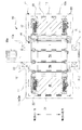
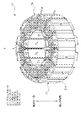
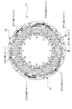
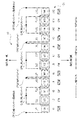
- FIG. 1 It is sectional drawing which shows the outline of the brushless motor which concerns on this invention. It is a perspective view which shows the stator unit of FIG. It is a view of arrow A of FIG. It is a developed view explaining the winding structure of the three-phase coil of FIG. It is a figure which shows the drive circuit (delta connection) by the winding structure of FIG. It is a figure corresponding to FIG. 3 of the stator unit of Embodiment 2. It is a developed view explaining the winding structure of the three-phase coil of FIG. It is a figure which shows the drive circuit (star connection) by the winding structure of FIG. It is a figure corresponding to FIG. 3 of the stator unit of Embodiment 3. It is a developed view explaining the winding structure of the three-phase coil of FIG.
- FIG. 1 is a cross-sectional view showing an outline of the brushless motor according to the present invention
- FIG. 2 is a perspective view showing the stator unit of FIG. 1
- FIG. 3 is a view taken along the line A of FIG. 2
- FIG. 4 is a view of FIG. A development view for explaining the winding structure of the phase coil is shown
- FIG. 5 shows a diagram showing a drive circuit (delta connection) according to the winding structure of FIG.
- the brushless motor 10 shown in FIG. 1 is a small brushless motor used as a drive source for electrical equipment (for example, an electric parking brake device) mounted on a vehicle such as an automobile. Therefore, the needs of the brushless motor 10 include further reduction in size and weight and improvement in vibration resistance. In this way, by adopting a brushless motor as the drive source of the electrical equipment, the electrical equipment can be controlled more finely.
- the brushless motor 10 includes a casing 11 (see the imaginary line in the figure) formed hollow by injection molding or the like of a molten aluminum material.
- the casing 11 includes a casing main body 12 formed in a substantially cylindrical shape, a ceiling wall portion 13 formed in a substantially disk shape, and a bottom wall portion 14 formed in a substantially disk shape.
- the casing main body 12, the ceiling wall portion 13 and the bottom wall portion 14 are integrated with each other, and a stator unit 20 functioning as a stator is firmly formed inside the casing main body 12 and on the inner peripheral wall 12a of the casing main body 12 by press fitting or the like. It is fixed to.
- a first bearing fixing portion 13a (see the imaginary line in the figure) formed in an annular shape and a step is provided at the central portion on the inner side in the radial direction of the ceiling wall portion 13.
- a first radial bearing RB1 (see an imaginary line in the drawing) that rotatably supports one side (upper side in the drawing) of the output shaft 33 in the axial direction is mounted on the first bearing fixing portion 13a.
- a ball bearing including an inner ring, an outer ring, and a steel ball is adopted as the first radial bearing RB1.
- a tubular radial bearing which is also called “metal”, can be adopted.
- one side (tip side) of the output shaft 33 in the axial direction protrudes from the central portion of the ceiling wall portion 13, and the serration portion 33a protrudes to the outside of the casing 11 of the output shaft 33.
- a drive object (not shown) such as a gear constituting the reduction mechanism is fixed to the serration portion 33a.
- a second bearing fixing portion 14a (see the imaginary line in the figure) formed in an annular shape and a step is provided at the central portion on the inner side in the radial direction of the bottom wall portion 14.
- a second radial bearing RB2 (see the imaginary line in the drawing) that rotatably supports the other side (lower side in the drawing) of the output shaft 33 in the axial direction is mounted on the second bearing fixing portion 14a.
- the second radial bearing RB2 also employs a ball bearing having an inner ring, an outer ring, and a steel ball.
- a tubular radial bearing which is also called “metal”, can be adopted.
- a rotor unit 30 (see the imaginary line in the figure) is rotatably provided inside the stator core 21 forming the stator unit 20 via a predetermined gap (air gap).
- the rotor unit 30 includes a rotor body (rotor) 31 in which a plurality of steel plates made of a magnetic material are laminated. Further, on the radial outer surface of the rotor main body 31, 10-pole permanent magnets 32 (not shown in detail) are provided side by side at equal intervals in the circumferential direction of the rotor main body 31.
- a brushless motor having an SPM (Surface Permanent Magnet) structure in which a permanent magnet 32 is mounted on the surface of the rotor main body 31 is adopted, but the brushless motor having the SPM structure is replaced with the brushless motor having the SPM structure. Therefore, a brushless motor having an IPM (Interior Permanent Magnet) structure in which a plurality of permanent magnets are embedded in the rotor main body 31 can also be adopted.
- SPM Surface Permanent Magnet
- IPM Interior Permanent Magnet
- an output shaft 33 made of a round steel rod having a predetermined length is fixed at the center of rotation of the rotor main body 31.
- One side (tip side) of the output shaft 33 in the axial direction is exposed to the outside of the casing 11 via the ceiling wall portion 13.
- the other side (base end side) of the output shaft 33 in the axial direction is not exposed to the outside of the casing 11.
- a serration portion 33a is provided at the tip end portion of the output shaft 33, and a drive object such as a gear is fixed to the serration portion 33a so as to be able to rotate (so as not to slip).
- the rotor unit 30 is composed of a rotor body 31, a permanent magnet 32, and an output shaft 33.
- the stator unit 20 is fixed to the inner peripheral wall 12a on the inner side in the radial direction of the casing main body 12 forming the casing 11.
- the stator unit 20 includes an annular stator core 21, and the stator core 21 is formed by laminating a plurality of steel plates made of a magnetic material.
- the stator core 21 is formed in an annular shape by connecting the divided cores CR (see FIG. 2) divided into a total of 12 pieces to each other in the circumferential direction of the stator unit 20.
- stator core 21 is firmly fixed to the casing 11 by press-fitting the outer peripheral wall 21a on the radial outer side of the stator core 21 into the inner peripheral wall 12a on the inner side in the radial direction of the casing body 12 at a predetermined pressure.
- a total of 12 teeth TH projecting toward the center of the stator core 21 are integrally provided inside the stator core 21 in the radial direction.
- the teeth TH is provided corresponding to the split core CR, and one teeth TH is provided for one split core CR.
- a total of 12 teeth THs are each equipped with an insulator 22 made of an insulating material such as plastic.
- a U-phase coil Cu, a V-phase coil Cv, and a W-phase coil Cw are respectively wound around each tooth TH by a centralized winding in a predetermined number of turns (25 turns, etc.) via an insulator 22.
- the U-phase coil Cu, the V-phase coil Cv, and the W-phase coil Cw are shaded in order to make it easier to understand the arrangement of the U-phase coil Cu, the V-phase coil Cv, and the W-phase coil Cw. Giving.
- the brushless motor 10 has a total of 12 teeth TH (12 slots in total). Further, the rotor unit 30 (see FIG. 1) includes a 10-pole permanent magnet 32 as described above. That is, the brushless motor 10 according to the present embodiment is a "10 pole 12 slot type" brushless motor.
- the rotor unit 30 is not limited to 10 poles, and for example, a 14-pole permanent magnet 32 may be provided.
- the brushless motor 10 can be miniaturized and finely tuned. It can be controlled and the generation of cogging torque can be minimized.
- the brushless motor 10 according to the present embodiment has specifications suitable for use as a drive source for electrical equipment mounted on a vehicle.
- the winding structure of the U-phase coil Cu, the V-phase coil Cv and the W-phase coil Cw for a total of 12 teeth TH and the drive current are distributed to the U-phase coil Cu, the V-phase coil Cv and the W-phase coil Cw.
- the connection structure for the U-phase bus bar, the V-phase bus bar, and the W-phase bus bar (not shown) will be described in detail with reference to FIGS. 3 to 5.
- a total of 12 teeth THs shown in FIG. 2 will be described by numbering them in the order of arrangement, such as the first teeth t1 to the twelfth teeth t12, with respect to the circumferential direction of the stator core 21. Further, a total of four U-phase coils Cu, V-phase coils Cv and W-phase coils Cw shown in FIG. 2 are respectively traced in the winding order, and U-phase coils U1 to U4 and V-phase coils V1 to V4 and W are respectively. The phase coils W1 to W4 will be described with reference numerals.
- FIG. 4 is a development view (360 degrees) of the first teeth t1 to the twelfth teeth t12 viewed from the center of the stator core 21, and the first teeth t1 to the first teeth t1 to 12 are viewed from the left side in the figure to the right side in the figure. 12 teeth t12 are arranged side by side in that order.
- the reference numeral CCW in FIG. 4 means that the winding direction of the coil is "counterclockwise”
- the reference numeral CW in FIG. 4 means that the winding direction of the coil is "clockwise”.
- the broken line indicates the U-phase coil
- the alternate long and short dash line indicates the V-phase coil
- the alternate long and short dash line indicates the W-phase coil.
- each of the first teeth t1 to 12th teeth t12 will later become U-phase coils U1 to U4, V-phase coils V1 to V4, and W-phase coils W1 to W4. It is possible to wind a continuous coil material of a book by so-called "one-stroke writing" without cutting it in the middle.
- the nozzle of the automatic winding machine (not shown) faces the inside in the radial direction thereof, and the first teeth t1 Follow the procedure for winding from to the 12th teeth t12 in this order.
- the U-phase coil U1 is wound around the first teeth t1 by concentrated winding in the CCW direction (counterclockwise direction) (25 turns, etc.).
- the nozzle of the automatic winding machine moves to the adjacent second tooth t2, and the U-phase coil U2 is wound around the second tooth t2 in a concentrated winding in the CW direction (clockwise direction) (25 turns). etc).
- the nozzle of the automatic winding machine moves to one side in the axial direction of the stator core 21 and moves between the third teeth t3 and the fourth teeth t4.
- the coil material is pulled out on one side of the stator core 21 in the axial direction and between the second teeth t2 and the third teeth t3, and the connection point CP2 is formed in the portion.
- the V-phase coil V1 is wound around the third teeth t3 in a concentrated winding in the CW direction (25 turns, etc.).
- the nozzle of the automatic winding machine moves to the adjacent fourth teeth t4, and the V-phase coil V2 is wound around the fourth teeth t4 in a concentrated winding in the CCW direction (25 turns, etc.).
- the nozzle of the automatic winding machine moves to one side in the axial direction of the stator core 21 and is arranged between the fourth teeth t4 and the fifth teeth t5.
- the coil material is pulled out on one side of the stator core 21 in the axial direction and between the fourth teeth t4 and the fifth teeth t5, and the connection point CP3 is formed in the portion.
- the in-phase coils (U-phase coils U1 and U2) are wound around the adjacent first and second teeth t1 and t2 in opposite directions. Further, coils having different phases (U-phase coil U2 and V-phase coil V1) are wound around the adjacent second and third teeth t2 and t3 in the same direction. Further, coils having the same phase (V-phase coils V1 and V2) are wound around the adjacent third and fourth teeth t3 and t4 in opposite directions.
- winding procedure (winding method) up to this point is the same for the subsequent fifth teeth t5 to twelfth teeth t12. Therefore, it is possible to control the nozzle of the automatic winding machine relatively easily.
- the W-phase coil W1 is wound in a concentrated winding in the CCW direction (25 turns, etc.).
- the nozzle of the automatic winding machine moves to the adjacent sixth teeth t6, and the W-phase coil W2 is wound around the sixth teeth t6 in a concentrated winding in the CW direction (25 turns, etc.).
- the nozzle of the automatic winding machine moves to one side in the axial direction of the stator core 21 and moves between the 7th teeth t7 and the 8th teeth t8.
- the coil material is pulled out on one side of the stator core 21 in the axial direction and between the sixth teeth t6 and the seventh teeth t7, and the connection point CP4 is formed in the portion.
- the U-phase coil U3 is wound around the 7th teeth t7 in a concentrated winding in the CW direction (25 turns, etc.).
- the nozzle of the automatic winding machine moves to the adjacent eighth teeth t8, and the U-phase coil U4 is wound around the eighth teeth t8 in a concentrated winding in the CCW direction (25 turns, etc.).
- the nozzle of the automatic winding machine moves to one side in the axial direction of the stator core 21 and is arranged between the 8th teeth t8 and the 9th teeth t9.
- the coil material is pulled out on one side of the stator core 21 in the axial direction and between the eighth teeth t8 and the ninth teeth t9, and the connection point CP5 is formed in the portion.
- the V-phase coil V3 is wound around the 9th teeth t9 in a concentrated winding in the CCW direction (25 turns, etc.).
- the nozzle of the automatic winding machine moves to the adjacent tenth teeth t10, and the V-phase coil V4 is wound around the tenth teeth t10 in a concentrated winding in the CW direction (25 turns, etc.).
- the nozzle of the automatic winding machine moves to one side in the axial direction of the stator core 21 and moves between the 11th teeth t11 and the 12th teeth t12.
- the coil material is pulled out on one side of the stator core 21 in the axial direction and between the 10th teeth t10 and the 11th teeth t11, and the connection point CP6 is formed in the portion.
- the W-phase coil W3 is wound around the 11th teeth t11 in a concentrated winding in the CW direction (25 turns, etc.).
- the nozzle of the automatic winding machine moves to the adjacent 12th teeth t12, and the W-phase coil W4 is wound around the 12th teeth t12 in a concentrated winding in the CCW direction (25 turns, etc.).
- the nozzle of the automatic winding machine moves to one side in the axial direction of the stator core 21 and is arranged between the twelfth teeth t12 and the first teeth t1.
- the U-phase coils U1 to U4, the V-phase coils V1 to V4, and the W-phase coils W1 to W4 which are made of one continuous coil material, are wound around all of the first teeth t1 to the twelfth teeth t12.
- the winding work by the automatic winding machine is completed. Therefore, a connection point CP7, which is the end of winding of the coil material, is formed between the 12th teeth t12 and the 1st teeth t1 on one side in the axial direction of the stator core 21.
- a pair of adjacent teeth is set as a set, and a coil having the same phase is wound around the pair of teeth.
- the U-phase coils U1 and U2 are wound around the adjacent first teeth t1 and the second teeth t2, respectively, and the V-phase coils are wound around the adjacent third teeth t3 and fourth teeth t4, respectively.
- U1 and V2 are wound respectively, and W-phase coils W1 and W2 are wound around the adjacent fifth teeth t5 and sixth teeth t6, respectively.
- two coil ends are pulled out from a pair of adjacent teeth. Specifically, as shown by the numbers in the brackets in FIG. 4, a total of 12 coil ends are pulled out on one side in the axial direction of the stator core 21.
- the coil material is wound with a single stroke without being cut in the middle, it is not necessary to provide 12 connection points, and 7 connection points CP1 to CP7 are sufficient. There is. Therefore, it is possible to simplify the electrical connection work of the U-phase bus bar, the V-phase bus bar, and the W-phase bus bar.
- U-phase bus bars, V-phase bus bars, and W-phase bus bars are electrically connected to the connection points CP1 to CP7 arranged on one side in the axial direction of the stator core 21 as shown below.
- one U-phase bus bar that supplies drive current to the four U-phase coils U1 to U4 is electrically connected to the connection point CP1, the connection point CP4, and the connection point CP7.
- one V-phase bus bar that supplies a drive current to the four V-phase coils V1 to V4 is electrically connected to the connection point CP2 and the connection point CP5.
- one W-phase bus bar that supplies a drive current to the four W-phase coils W1 to W4 is electrically connected to the connection point CP3 and the connection point CP6.
- the respective coils U1 to U4, V1 to V4, and W1 to W4 are connected to each other via the respective bus bars on one side in the axial direction of the stator core 21, and as shown in FIG. 5, the brushless motor 10
- the drive circuit becomes a "delta connection" drive circuit.
- the broken line (U-phase coil), the alternate long and short dash line (V-phase coil), and the two-dot chain wire (W-phase coil) are 2 respectively.
- welding means such as TIG (Tungsten Inert Gas) welding or fusing (heat caulking) is used for electrical connection at each connection point CP1 to CP7.
- TIG welding is a type of arc welding using electricity, and is a method of melting and welding a welding rod in an arc by using tungsten, which is a material that does not wear out on the electrode rod.
- fusing means that after mechanically fixing the coil material to the connection part (terminal) of the bus bar, the connection part is pressurized with a pair of electrodes to pass an electric current, and welding is performed by the heat generated at that time. How to do it.
- the coil material portion to which the U-phase bus bar is connected is "light-colored shaded”.
- the portion of the coil material to which the V-phase bus bar is connected is "shaded with a medium density”.
- the portion of the coil material to which the W-phase bus bar is connected is "dark shaded”.
- the pair of U-phase coils U1 and U2 and the pair of U-phase coils U3 and U4 are arranged to face each other so as to sandwich the center of the stator core 21 (180 degree arrangement). Further, the pair of V-phase coils V1 and V2 and the pair of V-phase coils V3 and V4 are arranged so as to face each other so as to sandwich the center of the stator core 21 (180 degree arrangement). Further, the pair of W-phase coils W1 and W2 and the pair of W-phase coils W3 and W4 are arranged so as to face each other so as to sandwich the center of the stator core 21 (180 degree arrangement).
- a pair of adjacent teeth TH (see FIG. 2) is set as a set, and a pair of coils having the same phase as the pair of teeth TH (see FIG. 2) (see FIG. 2).
- Cu and Cu, Cv and Cv, Cw and Cw) are wound.
- the drive circuit (delta connection) of the brushless motor 10 can be formed by connecting the coil on one side of the stator core 21 in the axial direction.
- FIG. 6 is a view corresponding to FIG. 3 of the stator unit of the second embodiment
- FIG. 7 is a developed view for explaining the winding structure of the three-phase coil of FIG. 6,
- FIG. 8 is based on the winding structure of FIG. The figure which shows the drive circuit (star connection) is shown respectively.
- the winding structure of the U-phase coil Cu, the V-phase coil Cv and the W-phase coil Cw for a total of 12 teeth TH (see FIG. 2).
- the connection structure for the U-phase bus bar, the V-phase bus bar, and the W-phase bus bar (not shown) that distribute the drive current to the U-phase coil Cu, the V-phase coil Cv, and the W-phase coil Cw are different.
- the U-phase coils U1 to U4 are later applied to the first teeth t1 to the twelfth teeth t12, respectively.
- One continuous coil material which is a V-phase coil V1 to V4 and a W-phase coil W1 to W4, can be wound by so-called "one-stroke writing" without cutting in the middle.
- connection point CP1 is used as the start of winding the coil material, and the U-phase coil U1 is wound around the first teeth t1 by concentrated winding in the CCW direction (counterclockwise direction). Will be done (25 turns, etc.).
- the nozzle of the automatic winding machine moves to the adjacent second tooth t2, and the U-phase coil U2 is wound around the second tooth t2 in a concentrated winding in the CW direction (clockwise direction) (25 turns). etc).
- connection point CP7 neutral point
- the V-phase coil V1 is wound around the third teeth t3 in a concentrated winding in the CCW direction (25 turns, etc.).
- the nozzle of the automatic winding machine moves to the adjacent fourth teeth t4, and the V-phase coil V2 is wound around the fourth teeth t4 in a concentrated winding in the CW direction (25 turns, etc.).
- the nozzle of the automatic winding machine moves to one side in the axial direction of the stator core 21 and is arranged between the fourth teeth t4 and the fifth teeth t5.
- the coil material is pulled out on one side of the stator core 21 in the axial direction and between the fourth teeth t4 and the fifth teeth t5.
- the portion of the coil material drawn out between the fourth teeth t4 and the fifth teeth t5 becomes a portion to be cut after the coil material is wound around all the teeth. There is.
- connection point CP2 is formed between the third teeth t3 and the fourth teeth t4, and the connection point CP3 is formed between the fourth teeth t4 and the fifth teeth t5.
- the in-phase coils (U-phase coils U1 and U2) are wound around the adjacent first and second teeth t1 and t2 in opposite directions. Further, coils having different phases (U-phase coil U2 and V-phase coil V1) are wound around the adjacent second and third teeth t2 and t3 in opposite directions. Further, coils having the same phase (V-phase coils V1 and V2) are wound around the adjacent third and fourth teeth t3 and t4 in opposite directions.
- winding procedure (winding method) up to this point is the same for the subsequent fifth teeth t5 to twelfth teeth t12. Therefore, it is possible to control the nozzle of the automatic winding machine relatively easily.
- the W-phase coil W1 is wound in a concentrated winding in the CCW direction (25 turns, etc.).
- the nozzle of the automatic winding machine moves to the adjacent sixth teeth t6, and the W-phase coil W2 is wound around the sixth teeth t6 in a concentrated winding in the CW direction (25 turns, etc.).
- connection point CP8 neutral point
- the U-phase coil U3 is wound around the 7th teeth t7 in a concentrated winding in the CCW direction (25 turns, etc.).
- the nozzle of the automatic winding machine moves to the adjacent eighth teeth t8, and the U-phase coil U4 is wound around the eighth teeth t8 in a concentrated winding in the CW direction (25 turns, etc.).
- the nozzle of the automatic winding machine moves to one side in the axial direction of the stator core 21 and is arranged between the 8th teeth t8 and the 9th teeth t9.
- the coil material is pulled out on one side of the stator core 21 in the axial direction and between the eighth teeth t8 and the ninth teeth t9.
- the portion of the coil material drawn out between the 8th teeth t8 and the 9th teeth t9 becomes a portion to be cut after the coil material is wound around all the teeth. There is.
- connection point CP4 is formed between the 7th teeth t7 and the 8th teeth t8, and the connection point CP5 is formed between the 8th teeth t8 and the 9th teeth t9.
- the V-phase coil V3 is wound around the 9th teeth t9 in a concentrated winding in the CCW direction (25 turns, etc.).
- the nozzle of the automatic winding machine moves to the adjacent tenth teeth t10, and the V-phase coil V4 is wound around the tenth teeth t10 in a concentrated winding in the CW direction (25 turns, etc.).
- the nozzle of the automatic winding machine moves to one side in the axial direction of the stator core 21 and moves between the 10th teeth t10 and the 11th teeth t11.
- the coil material is pulled out on one side of the stator core 21 in the axial direction and between the tenth tooth t10 and the eleventh tooth t11, and a connection point CP9 (neutral point) is formed in the portion.
- the W-phase coil W3 is wound around the 11th teeth t11 in a concentrated winding in the CCW direction (25 turns, etc.).
- the nozzle of the automatic winding machine moves to the adjacent 12th teeth t12, and the W-phase coil W4 is wound around the 12th teeth t12 in a concentrated winding in the CW direction (25 turns, etc.).
- the nozzle of the automatic winding machine moves to one side in the axial direction of the stator core 21 and is arranged between the 11th teeth t11 and the 12th teeth t12.
- the U-phase coils U1 to U4, the V-phase coils V1 to V4, and the W-phase coils W1 to W4 which are made of one continuous coil material, are wound around all of the first teeth t1 to the twelfth teeth t12.
- the winding work by the automatic winding machine is completed. Therefore, the connection point CP6, which is the end of winding of the coil material, is formed on one side of the stator core 21 in the axial direction and between the 11th teeth t11 and the 12th teeth t12.
- a pair of adjacent teeth is set as a set, and a coil having the same phase is wound around the pair of teeth. It is dressed up. Further, two coil ends are pulled out from a pair of adjacent teeth. Specifically, as shown by the numbers in the brackets in FIG. 7, a total of 12 coil ends are pulled out on one side in the axial direction of the stator core 21 as in the first embodiment.
- connection points CP1 to CP9 are sufficient.
- a neutral point bus bar (not shown) is required in addition to the U-phase bus bar, the V-phase bus bar, and the W-phase bus bar as described later.
- the U-phase bus bar, the V-phase bus bar, the W-phase bus bar, and the neutral point bus bar are described below at the connection points CP1 to CP9 arranged on one side of the stator core 21 in the axial direction. It is electrically connected like. That is, one U-phase bus bar that supplies drive currents to the four U-phase coils U1 to U4 is electrically connected to the connection point CP1 and the connection point CP4. Further, one V-phase bus bar that supplies a drive current to the four V-phase coils V1 to V4 is electrically connected to the connection point CP2 and the connection point CP5.
- one W-phase bus bar that supplies a drive current to the four W-phase coils W1 to W4 is electrically connected to the connection point CP3 and the connection point CP6.
- a neutral point bus bar forming a neutral point is electrically connected to the connection point CP7, the connection point CP8, and the connection point CP9.
- the respective coils U1 to U4, V1 to V4, and W1 to W4 are connected to each other via the respective bus bars on one side in the axial direction of the stator core 21, and as shown in FIG. 8, the brushless motor 10
- the drive circuit becomes a "star connection" drive circuit.
- a broken line (U-phase coil) and an alternate long and short dash line (V-phase coil) are directed from the connection point CP1 to the connection point CP6 via the connection points CP7 to CP9, which are neutral points.
- the two-dot chain wire (W-phase coil) are traced twice each, and it can be understood that one continuous coil material is wound with a single stroke without being cut in the middle.
- welding means such as TIG (Tungsten Inert Gas) welding or fusing (heat caulking) is used as in the first embodiment.
- the arrangement relationship of the U-phase coils U1 to U4, the V-phase coils V1 to V4 and the W-phase coils W1 to W4 is the same as that of the first embodiment (see FIG. 3). It has become.
- FIG. 7 also in the second embodiment, similarly to the first embodiment (see FIG. 4), the different phase is crossed on the other side (lower side in the figure) of the stator core 21 in the axial direction. There is no "crossover line” to straddle.
- FIG. 9 shows a view corresponding to FIG. 3 of the stator unit of the third embodiment
- FIG. 10 shows a development view for explaining the winding structure of the three-phase coil of FIG.
- the drive circuit of the brushless motor 10 is formed by so-called "star connection" as in the second embodiment, but the U-phase coil Cu for a total of 12 teeth TH (see FIG. 2) is formed.
- the winding structure of the V-phase coil Cv and the W-phase coil Cw (see FIG. 2) is slightly different from that of the second embodiment.
- the drive circuit of the brushless motor 10 in the third embodiment is the same as that in FIG.
- the U-phase coils U1 to U4 are later applied to the first teeth t1 to the twelfth teeth t12, respectively.
- One continuous coil material which is a V-phase coil V1 to V4 and a W-phase coil W1 to W4, can be wound by so-called "one-stroke writing" without cutting in the middle.
- connection point CP1 is set as the winding start of the coil material, and the U-phase coil U1 is wound around the first teeth t1 by concentrated winding in the CCW direction (counterclockwise direction). Will be done (25 turns, etc.).
- the nozzle of the automatic winding machine moves to the adjacent second teeth t2, and the U-phase coil U2 is wound around the second teeth t2 in a concentrated winding in the CW direction (clockwise direction) (25 turns). etc).
- connection point CP7 neutral point
- the V-phase coil V1 is wound around the 4th teeth t4 in a concentrated winding in the CW direction (25 turns, etc.).
- the nozzle of the automatic winding machine moves to the adjacent third tooth t3, and the V-phase coil V2 is wound around the third tooth t3 in a concentrated winding in the CCW direction (25 turns, etc.).
- the coil material is first wound around the fourth tooth t4, and then the coil material is wound around the third tooth t3.
- the nozzle of the automatic winding machine moves to one side in the axial direction of the stator core 21 and is arranged between the fourth teeth t4 and the fifth teeth t5.
- the coil material is pulled out on one side of the stator core 21 in the axial direction and between the third tooth t3 and the fifth tooth t5.
- the portion of the coil material drawn out between the third tooth t3 and the fifth tooth t5 becomes a portion to be cut after winding the coil material around all the teeth.
- connection point CP2 is formed between the third teeth t3 and the fourth teeth t4, and the connection point CP3 is formed between the fourth teeth t4 and the fifth teeth t5.
- the W-phase coil W1 is wound in a concentrated winding in the CCW direction (25 turns, etc.).
- the nozzle of the automatic winding machine moves to the adjacent sixth teeth t6, and the W-phase coil W2 is wound around the sixth teeth t6 in a concentrated winding in the CW direction (25 turns, etc.).
- the nozzle of the automatic winding machine moves to one side in the axial direction of the stator core 21 and moves between the 8th teeth t8 and the 9th teeth t9.
- the coil material is pulled out on one side of the stator core 21 in the axial direction and between the sixth tooth t6 and the eighth tooth t8, and a connection point CP8 (neutral point) is formed in the portion.
- the U-phase coil U3 is wound around the 8th teeth t8 in a concentrated winding in the CW direction (25 turns, etc.).
- the nozzle of the automatic winding machine moves to the adjacent 7th teeth t7, and the U-phase coil U4 is wound around the 7th teeth t7 in a concentrated winding in the CCW direction (25 turns, etc.).
- the coil material is first wound around the eighth tooth t8, and then the coil material is wound around the seventh tooth t7.
- the nozzle of the automatic winding machine moves to one side in the axial direction of the stator core 21 and is arranged between the 8th teeth t8 and the 9th teeth t9.
- the coil material is pulled out on one side of the stator core 21 in the axial direction and between the 7th teeth t7 and the 9th teeth t9.
- the portion of the coil material drawn out between the 7th teeth t7 and the 9th teeth t9 becomes a portion to be cut after the coil material is wound around all the teeth. There is.
- connection point CP4 is formed between the 7th teeth t7 and the 8th teeth t8, and the connection point CP5 is formed between the 8th teeth t8 and the 9th teeth t9.
- the V-phase coil V3 is wound around the 9th teeth t9 in a concentrated winding in the CCW direction (25 turns, etc.).
- the nozzle of the automatic winding machine moves to the adjacent tenth teeth t10, and the V-phase coil V4 is wound around the tenth teeth t10 in a concentrated winding in the CW direction (25 turns, etc.).
- the nozzle of the automatic winding machine moves to one side in the axial direction of the stator core 21 and moves between the twelfth teeth t12 and the first teeth t1.
- the coil material is pulled out on one side of the stator core 21 in the axial direction and between the tenth tooth t10 and the twelfth tooth t12, and a connection point CP9 (neutral point) is formed in the portion.
- the W-phase coil W3 is wound around the 12th teeth t12 in a concentrated winding in the CW direction (25 turns, etc.).
- the nozzle of the automatic winding machine moves to the adjacent eleventh teeth t11, and the W-phase coil W4 is wound around the eleventh teeth t11 in a concentrated winding in the CCW direction (25 turns, etc.).
- the coil material is first wound around the 12th teeth t12, and then the coil material is wound around the 11th teeth t11.
- the nozzle of the automatic winding machine moves to one side in the axial direction of the stator core 21 and is arranged between the 11th teeth t11 and the 12th teeth t12.
- the U-phase coils U1 to U4, the V-phase coils V1 to V4, and the W-phase coils W1 to W4 which are made of one continuous coil material, are wound around all of the first teeth t1 to the twelfth teeth t12.
- the winding work by the automatic winding machine is completed. Therefore, the connection point CP6, which is the end of winding of the coil material, is formed on one side of the stator core 21 in the axial direction and between the 11th teeth t11 and the 12th teeth t12.
- the U-phase bus bar, the V-phase bus bar, the W-phase bus bar, and the middle are relative to the connection points CP1 to CP9 arranged on one side in the axial direction of the stator core 21.
- the sex point busbar is electrically connected. Therefore, also in the third embodiment, the drive circuit of the brushless motor 10 is a so-called “star connection” drive circuit (see FIG. 8).
- the brushless motor 10 is shown as a "10 pole 12 slot type” brushless motor, and can be set to the "14 pole 12 slot type”. Is not limited to this, and may be another pole number.
- the brushless motor 10 is used as a drive source for an electrical device mounted on a vehicle such as an automobile, but the present invention is not limited to this, and for example, an electric motorcycle or an electric motor. It can also be applied to a drive source such as a wheelchair.
- each component in each of the above embodiments is arbitrary as long as the present invention can be achieved, and are not limited to each of the above embodiments.
Landscapes
- Engineering & Computer Science (AREA)
- Power Engineering (AREA)
- Windings For Motors And Generators (AREA)
- Manufacture Of Motors, Generators (AREA)
Abstract
渡り線を無くして、小型軽量化および信頼性向上を両立させることが可能なブラシレスモータを提供する。隣り合う一対のティースTHを一組として、一組となった一対のティースTHに同相のコイル(CuとCu,CvとCv,CwとCw)を巻装する。これにより、一組となった一対のティースTHにおいてコイル端を2つに減らし、かつこれらをステータコア21の軸方向一側に引き出すことができる。よって、ステータコア21の軸方向一側でコイル端を結線することで、ブラシレスモータ10の駆動回路(デルタ結線またはスター結線)を形成できる。したがって、従前のようなステータコアの軸方向他側において90度間隔で配置された同相のコイル同士を接続する「渡り線」を無くすことができる。よって、ブラシレスモータ10の小型軽量化および信頼性向上を両立させることが可能となる。
Description
本発明は、環状のステータコアと、ステータコアの径方向内側に回転自在に設けられたロータと、を有するブラシレスモータに関する。
例えば、特許文献1には、複数のティースが設けられた環状のステータコアと、複数のティースのそれぞれに巻装されたU相コイル,V相コイルおよびW相コイルと、ステータコアの径方向内側に回転自在に設けられたロータと、を有するブラシレスモータが記載されている。そして、U相コイル,V相コイルおよびW相コイルは、ステータコアの軸方向一側において、それぞれデルタ結線またはスター結線となるように電気的に接続されている。
しかしながら、上述の特許文献1に記載されたブラシレスモータでは、U相コイルが巻装される4つのティースと、V相コイルが巻装される4つのティースと、W相コイルが巻装される4つのティースとが、それぞれステータコアの周方向に等間隔(90度間隔)で配置されている。そして、90度間隔で配置された同相のコイル同士を、ステータコアの軸方向他側において、渡り線を介して電気的に接続している。
すなわち、上述の特許文献1に記載の技術では、同相のコイル同士を接続する渡り線を、異相のコイルを跨ぐようにして設けているため、その分コストアップに繋がるばかりか、ブラシレスモータのさらなる小型軽量化への対応が難しいという問題があった。また、渡り線が異相のコイルを跨ぐため、駆動時の振動等により渡り線と異相のコイルとが互いに擦れて皮膜が剥がれて、互いに短絡する虞があった。
このように、上述の特許文献1に記載の技術では、渡り線を備えるが故に、さらなる小型軽量化への対応が難しく、かつ耐振動性(信頼性)を向上させるのが難しいという問題があった。
本発明の目的は、渡り線を無くして、小型軽量化および信頼性向上を両立させることが可能なブラシレスモータを提供することにある。
本発明の一態様では、環状のステータコアと、前記ステータコアの径方向内側に回転自在に設けられたロータと、を有するブラシレスモータであって、前記ステータコアに設けられ、当該ステータコアの中心に向けて突出され、かつ前記ステータコアの周方向に順番に並べられた第1ティースないし第12ティースと、前記第1ティースないし第12ティースのそれぞれに巻装されたU相コイル,V相コイルおよびW相コイルと、を備え、前記ステータコアの中心から前記第1ティースないし第12ティースを見たときに、前記U相コイルは、第1および第8ティースに反時計回り方向に巻装され、かつ第2および第7ティースに時計回り方向に巻装され、前記V相コイルは、第3および第10ティースに時計回り方向に巻装され、かつ第4および第9ティースに反時計回り方向に巻装され、前記W相コイルは、第5および第12ティースに反時計回り方向に巻装され、かつ第6および第11ティースに時計回り方向に巻装されており、前記U相コイル,V相コイルおよびW相コイルが、前記ステータコアの軸方向一側で互いにデルタ結線されていることを特徴とする。
本発明の他の態様では、環状のステータコアと、前記ステータコアの径方向内側に回転自在に設けられたロータと、を有するブラシレスモータであって、前記ステータコアに設けられ、当該ステータコアの中心に向けて突出され、かつ前記ステータコアの周方向に順番に並べられた第1ティースないし第12ティースと、前記第1ティースないし第12ティースのそれぞれに巻装されたU相コイル,V相コイルおよびW相コイルと、を備え、前記ステータコアの中心から前記第1ティースないし第12ティースを見たときに、前記U相コイルは、第1および第7ティースに反時計回り方向に巻装され、かつ第2および第8ティースに時計回り方向に巻装され、前記V相コイルは、第3および第9ティースに反時計回り方向に巻装され、かつ第4および第10ティースに時計回り方向に巻装され、前記W相コイルは、第5および第11ティースに反時計回り方向に巻装され、かつ第6および第12ティースに時計回り方向に巻装されており、前記U相コイル,V相コイルおよびW相コイルが、前記ステータコアの軸方向一側で互いにスター結線されていることを特徴とする。
本発明によれば、隣り合う一対のティースを一組として、一組となった一対のティースに同相のコイルを巻装する。これにより、一組となった一対のティースにおいてコイルを2本に減らし、かつこれらをステータコアの軸方向一側に引き出すことができる。よって、ステータコアの軸方向一側でコイルを結線することで、ブラシレスモータの駆動回路(デルタ結線またはスター結線)を形成できる。したがって、従前のようなステータコアの軸方向他側において90度間隔で配置された同相のコイル同士を接続する「渡り線」を無くすことができる。よって、ブラシレスモータの小型軽量化および信頼性向上を両立させることが可能となる。
以下、本発明の実施の形態1について、図面を用いて詳細に説明する。
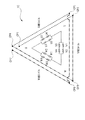
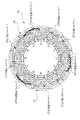
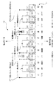
図1は本発明に係るブラシレスモータの概要を示す断面図を、図2は図1のステータユニットを示す斜視図を、図3は図2のA矢視図を、図4は図3の三相のコイルの巻装構造を説明する展開図を、図5は図4の巻装構造による駆動回路(デルタ結線)を示す図をそれぞれ示している。
図1に示されるブラシレスモータ10は、自動車等の車両に搭載される電装機器(例えば、電動パーキングブレーキ装置等)の駆動源に用いられる小型のブラシレスモータである。したがって、ブラシレスモータ10のニーズには、さらなる小型軽量化や耐振動性の向上等がある。このように、電装機器の駆動源にブラシレスモータを採用することで、電装機器をよりきめ細かく制御可能となっている。
ブラシレスモータ10は、溶融したアルミ材料を射出成形等することで中空に形成されたケーシング11(図中想像線参照)を備えている。ケーシング11は、略筒状に形成されたケーシング本体12と、略円盤状に形成された天井壁部13と、略円盤状に形成された底壁部14と、を備えている。これらのケーシング本体12,天井壁部13および底壁部14は互いに一体化されており、その内部でかつケーシング本体12の内周壁12aには、固定子として機能するステータユニット20が圧入等により強固に固定されている。
天井壁部13の径方向内側の中心部分には、環状かつ段付きに形成された第1ベアリング固定部13a(図中想像線参照)が設けられている。そして、第1ベアリング固定部13aには、出力軸33の軸方向一側(図中上側)を回転自在に支持する第1ラジアル軸受RB1(図中想像線参照)が装着されている。なお、第1ラジアル軸受RB1には、内輪,外輪および鋼球を備えたボールベアリングが採用される。ただし、より小型軽量化に対応するために、所謂「メタル」とも呼ばれる管状のラジアル軸受を採用することもできる。
そして、天井壁部13の中心部分からは、出力軸33の軸方向一側(先端側)が突出されており、この出力軸33のケーシング11の外部に突出された部分には、セレーション部33aが設けられている。セレーション部33aには、例えば、減速機構を構成するギヤ等の駆動対象物(図示せず)が固定されるようになっている。
底壁部14の径方向内側の中心部分には、環状かつ段付きに形成された第2ベアリング固定部14a(図中想像線参照)が設けられている。そして、第2ベアリング固定部14aには、出力軸33の軸方向他側(図中下側)を回転自在に支持する第2ラジアル軸受RB2(図中想像線参照)が装着されている。なお、第2ラジアル軸受RB2においても、内輪,外輪および鋼球を備えたボールベアリングが採用される。ただし、より小型軽量化に対応するために、所謂「メタル」とも呼ばれる管状のラジアル軸受を採用することもできる。
ステータユニット20を形成するステータコア21の径方向内側には、所定の隙間(エアギャップ)を介してロータユニット30(図中想像線参照)が回転自在に設けられている。ロータユニット30は、磁性体よりなる鋼板を複数枚積層してなるロータ本体(ロータ)31を備えている。また、ロータ本体31の径方向外側の表面には、10極の永久磁石32(詳細図示せず)が、ロータ本体31の周方向に等間隔で並べて設けられている。
ここで、本実施の形態のブラシレスモータ10では、ロータ本体31の表面に永久磁石32を装着したSPM(Surface Permanent Magnet)構造のブラシレスモータを採用しているが、当該SPM構造のブラシレスモータに変えて、ロータ本体31の内部に複数の永久磁石を埋め込んだIPM(Interior Permanent Magnet)構造のブラシレスモータを採用することもできる。
また、ロータ本体31の回転中心には、所定の長さの丸鋼棒よりなる出力軸33が固定されている。そして、出力軸33の軸方向一側(先端側)は、天井壁部13を介してケーシング11の外部に露出されている。これに対し、出力軸33の軸方向他側(基端側)は、ケーシング11の外部に露出されていない。出力軸33の先端部分には、セレーション部33aが設けられ、セレーション部33aには、ギヤ等の駆動対象物が供回り可能に(空転しないように)固定されている。なお、ロータユニット30は、ロータ本体31,永久磁石32および出力軸33によって構成されている。
図1ないし図3に示されるように、ケーシング11を形成するケーシング本体12の径方向内側の内周壁12aには、ステータユニット20が固定されている。ステータユニット20は、環状のステータコア21を備え、ステータコア21は、磁性体よりなる鋼板を複数枚積層して形成されている。なお、ステータコア21は、合計12個に分割された分割コアCR(図2参照)を、ステータユニット20の周方向に互いに連結することで、環状に形成されている。
そして、ステータコア21の径方向外側の外周壁21aを、ケーシング本体12の径方向内側の内周壁12aに所定圧で圧入することで、ステータコア21はケーシング11に強固に固定される。そして、ステータコア21の径方向内側には、当該ステータコア21の中心に向けて突出された合計12個のティースTH(図1および図2参照)が一体に設けられている。ここで、ティースTHは分割コアCRに対応して設けられ、1つの分割コアCRに1つのティースTHが設けられている。
また、合計12個のティースTHには、プラスチック等の絶縁材料からなるインシュレータ22がそれぞれ装着されている。そして、それぞれのティースTHには、インシュレータ22を介して、U相コイルCu,V相コイルCvおよびW相コイルCwが、それぞれ集中巻により所定の巻数(25ターン等)で巻装されている。なお、図2では、U相コイルCu,V相コイルCvおよびW相コイルCwの配置関係を分かり易くするために、U相コイルCu,V相コイルCvおよびW相コイルCwのそれぞれに網掛けを施している。
このように、本実施の形態に係るブラシレスモータ10では、合計12個のティースTH(合計12個のスロット)を備えている。また、ロータユニット30(図1参照)は、上述のように10極の永久磁石32を備えている。すなわち、本実施の形態に係るブラシレスモータ10は、「10極12スロット形」のブラシレスモータとなっている。
ただし、ロータユニット30には、10極に限らず、例えば14極の永久磁石32を設けても良く、永久磁石32を10極あるいは14極に設定することで、ブラシレスモータ10を小型化しつつきめ細かく制御可能とし、かつコギングトルクの発生を最小限に抑えることが可能となる。言い換えれば、本実施の形態に係るブラシレスモータ10は、車両に搭載される電装機器の駆動源に用いて好適な仕様となっている。
次に、合計12個のティースTHに対するU相コイルCu,V相コイルCvおよびW相コイルCwの巻装構造と、U相コイルCu,V相コイルCvおよびW相コイルCwに駆動電流を分配するU相バスバー,V相バスバーおよびW相バスバー(図示せず)に対する結線構造について、図3ないし図5を用いて詳細に説明する。
以下の説明では、図2に示される合計12個のティースTHを、ステータコア21の周方向に対して、第1ティースt1ないし第12ティースt12のように並び順に番号を付して説明する。また、図2に示される合計4つずつのU相コイルCu,V相コイルCvおよびW相コイルCwを、それぞれ巻装順に倣って、U相コイルU1~U4,V相コイルV1~V4およびW相コイルW1~W4のように符号を付して説明する。
また、図3ないし図5において、ステータユニット20の軸方向一側に引き出されたU相コイルU1~U4,V相コイルV1~V4およびW相コイルW1~W4に付された黒点のCP1~CP7は、U相コイルU1~U4,V相コイルV1~V4およびW相コイルW1~W4におけるU相バスバー,V相バスバーおよびW相バスバーに対する電気的な接続点を示している。
なお、図4は、ステータコア21の中心から第1ティースt1ないし第12ティースt12を見た展開図(360度)であって、図中左側から図中右側に向けて、第1ティースt1ないし第12ティースt12がその順番で並んで配置されている。また、図4の符号CCWは、コイルの巻き方向が「反時計回り方向」であることを意味し、図4の符号CWは、コイルの巻き方向が「時計回り方向」であることを意味している。さらに、図4および図5では、破線がU相コイルを、一点鎖線がV相コイルを、二点鎖線がW相コイルを、それぞれ示している。
図3ないし図5に示されるように、第1ティースt1ないし第12ティースt12のそれぞれには、後でU相コイルU1~U4,V相コイルV1~V4およびW相コイルW1~W4となる1本の連続したコイル材を、途中で切断せずに所謂「一筆書き」で巻装可能となっている。なお、本実施の形態では、複数の分割コアCR(図2参照)を環状に組み立ててから、その径方向内側に自動巻線機のノズル(図示せず)を臨ませて、第1ティースt1から第12ティースt12までこの順番で巻装する手順を踏む。
具体的には、接続点CP1をコイル材の巻き始めとして、第1ティースt1には、U相コイルU1がCCW方向(反時計回り方向)に集中巻きで巻装される(25ターン等)。その後、自動巻線機のノズルが隣の第2ティースt2に移動して、第2ティースt2には、U相コイルU2がCW方向(時計回り方向)に集中巻きで巻装される(25ターン等)。
次いで、自動巻線機のノズルがステータコア21の軸方向一側に移動し、かつ第3ティースt3と第4ティースt4との間に移動する。これにより、ステータコア21の軸方向一側で、かつ第2ティースt2と第3ティースt3との間にコイル材が引き出されて、当該部分に接続点CP2が形成される。
その後、第3ティースt3には、V相コイルV1がCW方向に集中巻で巻装される(25ターン等)。これに引き続き、自動巻線機のノズルが隣の第4ティースt4に移動して、第4ティースt4には、V相コイルV2がCCW方向に集中巻きで巻装される(25ターン等)。
次いで、自動巻線機のノズルがステータコア21の軸方向一側に移動し、かつ第4ティースt4と第5ティースt5との間に配置される。これにより、ステータコア21の軸方向一側で、かつ第4ティースt4と第5ティースt5との間にコイル材が引き出されて、当該部分に接続点CP3が形成される。
このように、本実施の形態では、隣り合う第1および第2ティースt1,t2に、同相のコイル(U相コイルU1,U2)が、互いに逆向きで巻装される。また、隣り合う第2および第3ティースt2,t3に、異相のコイル(U相コイルU2,V相コイルV1)が、互いに同じ向きで巻装される。さらに、隣り合う第3および第4ティースt3,t4に、同相のコイル(V相コイルV1,V2)が、互いに逆向きで巻装される。
ここまでの巻装手順(巻き方)は、それ以降の第5ティースt5ないし第12ティースt12においても同様の巻装手順となっている。したがって、自動巻線機のノズルの制御を、比較的容易に行うことが可能となっている。
そして、第5ティースt5には、W相コイルW1がCCW方向に集中巻きで巻装される(25ターン等)。その後、自動巻線機のノズルが隣の第6ティースt6に移動して、第6ティースt6には、W相コイルW2がCW方向に集中巻きで巻装される(25ターン等)。
次いで、自動巻線機のノズルがステータコア21の軸方向一側に移動し、かつ第7ティースt7と第8ティースt8との間に移動する。これにより、ステータコア21の軸方向一側で、かつ第6ティースt6と第7ティースt7との間にコイル材が引き出されて、当該部分に接続点CP4が形成される。
その後、第7ティースt7には、U相コイルU3がCW方向に集中巻で巻装される(25ターン等)。これに引き続き、自動巻線機のノズルが隣の第8ティースt8に移動して、第8ティースt8には、U相コイルU4がCCW方向に集中巻きで巻装される(25ターン等)。
次いで、自動巻線機のノズルがステータコア21の軸方向一側に移動し、かつ第8ティースt8と第9ティースt9との間に配置される。これにより、ステータコア21の軸方向一側で、かつ第8ティースt8と第9ティースt9との間にコイル材が引き出されて、当該部分に接続点CP5が形成される。
その後、第9ティースt9には、V相コイルV3がCCW方向に集中巻きで巻装される(25ターン等)。これに引き続き、自動巻線機のノズルが隣の第10ティースt10に移動して、第10ティースt10には、V相コイルV4がCW方向に集中巻きで巻装される(25ターン等)。
次いで、自動巻線機のノズルがステータコア21の軸方向一側に移動し、かつ第11ティースt11と第12ティースt12との間に移動する。これにより、ステータコア21の軸方向一側で、かつ第10ティースt10と第11ティースt11との間にコイル材が引き出されて、当該部分に接続点CP6が形成される。
その後、第11ティースt11には、W相コイルW3がCW方向に集中巻で巻装される(25ターン等)。これに引き続き、自動巻線機のノズルが隣の第12ティースt12に移動して、第12ティースt12には、W相コイルW4がCCW方向に集中巻きで巻装される(25ターン等)。
次いで、自動巻線機のノズルがステータコア21の軸方向一側に移動し、かつ第12ティースt12と第1ティースt1との間に配置される。これにより、第1ティースt1ないし第12ティースt12の全てに、1本の連続したコイル材からなるU相コイルU1~U4,V相コイルV1~V4およびW相コイルW1~W4が巻装されて、自動巻線機による巻装作業が完了する。よって、ステータコア21の軸方向一側で、かつ第12ティースt12と第1ティースt1との間に、コイル材の巻き終わりである接続点CP7が形成される。
ここで、図4に示されるように、隣り合う一対のティースを一組として、一組となった一対のティースに同相のコイルが巻装されている。具体的には、例えば、隣り合う第1ティースt1および第2ティースt2には、U相コイルU1,U2がそれぞれ巻装され、隣り合う第3ティースt3および第4ティースt4には、V相コイルU1,V2がそれぞれ巻装され、隣り合う第5ティースt5および第6ティースt6には、W相コイルW1,W2がそれぞれ巻装されている。
また、隣り合う一組となった一対のティースからは、2本のコイル端が引き出されている。具体的には、図4の鉤括弧の数字で示されるように、ステータコア21の軸方向一側には、合計12本のコイル端が引き出されている。ここで、本実施の形態では、コイル材を途中で切断せずに一筆書きで巻装するため、接続点を12個設けずに済み、接続点CP1~CP7の7個で済むようになっている。よって、U相バスバー,V相バスバーおよびW相バスバーの電気的な接続作業を簡素化することが可能となる。
そして、図3ないし図5に示されるように、ステータコア21の軸方向一側に配置された接続点CP1~CP7には、U相バスバー,V相バスバーおよびW相バスバーが下記のように電気的に接続される。つまり、接続点CP1,接続点CP4および接続点CP7に、4つのU相コイルU1~U4に駆動電流を供給する1つのU相バスバーが電気的に接続される。また、接続点CP2および接続点CP5に、4つのV相コイルV1~V4に駆動電流を供給する1つのV相バスバーが電気的に接続される。さらに、接続点CP3および接続点CP6に、4つのW相コイルW1~W4に駆動電流を供給する1つのW相バスバーが電気的に接続される。
これにより、それぞれのコイルU1~U4,V1~V4,W1~W4が、ステータコア21の軸方向一側でそれぞれのバスバーを介して互いに結線されて、図5に示されるように、ブラシレスモータ10の駆動回路が「デルタ結線」の駆動回路となる。なお、図4および図5に示されるように、接続点CP1から接続点CP7に向けて、破線(U相コイル),一点鎖線(V相コイル)および二点鎖線(W相コイル)をそれぞれ2回ずつ辿ることで、1本の連続したコイル材を途中で切断せずに一筆書きで巻装されることが理解できる。
また、それぞれの接続点CP1~CP7における電気的な接続には、TIG(Tungsten Inert Gas)溶接あるいはヒュージング(熱かしめ)等の溶接手段が用いられる。前者の「TIG溶接」とは、電気を用いたアーク溶接の一種であって、電極棒に消耗しない材料のタングステンを使用して、溶接棒をアーク中で溶融して溶接する方法である。これに対し、後者の「ヒュージング」とは、コイル材をバスバーの接続部分(端子)に機械的に固定した後に、一対の電極で接続部分を加圧して電流を流し、その時の発熱で溶接する方法である。
さらに、図3では、U相バスバーの接続部分を分かり易くするために、U相バスバーが接続されるコイル材の部分に「淡色の網掛け」を施している。また、V相バスバーの接続部分を分かり易くするために、V相バスバーが接続されるコイル材の部分に「中位の濃さの網掛け」を施している。さらに、W相バスバーの接続部分を分かり易くするために、W相バスバーが接続されるコイル材の部分に「濃色の網掛け」を施している。
また、図3に示されるように、一対のU相コイルU1,U2および一対のU相コイルU3,U4は、ステータコア21の中心を挟むようにして、互いに対向配置されている(180度配置)。さらに、一対のV相コイルV1,V2および一対のV相コイルV3,V4は、ステータコア21の中心を挟むようにして、互いに対向配置されている(180度配置)。また、一対のW相コイルW1,W2および一対のW相コイルW3,W4は、ステータコア21の中心を挟むようにして、互いに対向配置されている(180度配置)。
さらに、図4に示されるように、ステータコア21の軸方向他側(図中下側)には、異相を横切るようにして跨ぐ「渡り線」が設けられていない。したがって、その分、コイル材の消費が抑えられて、コスト低減を実現しつつ、ステータユニットの軸方向寸法が詰められる。また、異相を横切るようにして跨ぐ渡り線が無いため、異相のコイル同士が交差して擦れるようなことも無い。よって、U相,V相およびW相コイルのそれぞれの表面の絶縁皮膜が剥がれることが無く、短絡等の不具合を完全に無くして耐振動性(信頼性)が向上する。
以上詳述したように、本実施の形態に係るブラシレスモータ10によれば、隣り合う一対のティースTH(図2参照)を一組として、一組となった一対のティースTHに同相のコイル(CuとCu,CvとCv,CwとCw)を巻装する。これにより、一組となった一対のティースTHにおいてコイル端を2本に減らし、かつこれらをステータコア21の軸方向一側に引き出すことができる。よって、ステータコア21の軸方向一側でコイルを結線することで、ブラシレスモータ10の駆動回路(デルタ結線)を形成できる。したがって、従前のようなステータコアの軸方向他側において90度間隔で配置された同相のコイル同士を接続する「渡り線」を無くすことができる。よって、ブラシレスモータ10の小型軽量化および信頼性向上を両立させることが可能となる。
次に、本発明の実施の形態2について、図面を用いて詳細に説明する。なお、上述した実施の形態1と同様の機能を有する部分については同一の記号を付し、その詳細な説明を省略する。
図6は実施の形態2のステータユニットの図3に対応した図を、図7は図6の三相のコイルの巻装構造を説明する展開図を、図8は図7の巻装構造による駆動回路(スター結線)を示す図をそれぞれ示している。
実施の形態2では、実施の形態1に比して、合計12個のティースTH(図2参照)に対するU相コイルCu,V相コイルCvおよびW相コイルCw(図2参照)の巻装構造と、U相コイルCu,V相コイルCvおよびW相コイルCwに駆動電流を分配するU相バスバー,V相バスバーおよびW相バスバー(図示せず)に対する結線構造と、が異なっている。
図6ないし図8に示されるように、実施の形態2においても、実施の形態1と同様に、第1ティースt1ないし第12ティースt12のそれぞれに対して、後でU相コイルU1~U4,V相コイルV1~V4およびW相コイルW1~W4となる1本の連続したコイル材を、途中で切断せずに所謂「一筆書き」で巻装可能となっている。
具体的には、図7に示されるように、接続点CP1をコイル材の巻き始めとして、第1ティースt1には、U相コイルU1がCCW方向(反時計回り方向)に集中巻きで巻装される(25ターン等)。その後、自動巻線機のノズルが隣の第2ティースt2に移動して、第2ティースt2には、U相コイルU2がCW方向(時計回り方向)に集中巻きで巻装される(25ターン等)。
次いで、自動巻線機のノズルがステータコア21の軸方向一側に移動し、かつ第2ティースt2と第3ティースt3との間に移動する。これにより、ステータコア21の軸方向一側で、かつ第2ティースt2との第3ティースt3との間にコイル材が引き出されて、当該部分に接続点CP7(中性点)が形成される。
その後、第3ティースt3には、V相コイルV1がCCW方向に集中巻で巻装される(25ターン等)。これに引き続き、自動巻線機のノズルが隣の第4ティースt4に移動して、第4ティースt4には、V相コイルV2がCW方向に集中巻きで巻装される(25ターン等)。
次いで、自動巻線機のノズルがステータコア21の軸方向一側に移動し、かつ第4ティースt4と第5ティースt5との間に配置される。これにより、ステータコア21の軸方向一側で、かつ第4ティースt4と第5ティースt5との間にコイル材が引き出される。なお、ここで、第4ティースt4と第5ティースt5との間に引き出されたコイル材の部分は、当該コイル材を全てのティースに巻装した後で切断(Cut)される箇所となっている。
これにより、第3ティースt3と第4ティースt4との間に、接続点CP2が形成され、かつ第4ティースt4と第5ティースt5との間に、接続点CP3が形成される。
このように、本実施の形態では、隣り合う第1および第2ティースt1,t2に、同相のコイル(U相コイルU1,U2)が、互いに逆向きで巻装される。また、隣り合う第2および第3ティースt2,t3に、異相のコイル(U相コイルU2,V相コイルV1)が、互いに逆向きで巻装される。さらに、隣り合う第3および第4ティースt3,t4に、同相のコイル(V相コイルV1,V2)が、互いに逆向きで巻装される。
ここまでの巻装手順(巻き方)は、それ以降の第5ティースt5ないし第12ティースt12においても同様の巻装手順となっている。したがって、自動巻線機のノズルの制御を、比較的容易に行うことが可能となっている。
そして、第5ティースt5には、W相コイルW1がCCW方向に集中巻きで巻装される(25ターン等)。その後、自動巻線機のノズルが隣の第6ティースt6に移動して、第6ティースt6には、W相コイルW2がCW方向に集中巻きで巻装される(25ターン等)。
次いで、自動巻線機のノズルがステータコア21の軸方向一側に移動し、かつ第6ティースt6と第7ティースt7との間に移動する。これにより、ステータコア21の軸方向一側で、かつ第6ティースt6との第7ティースt7との間にコイル材が引き出されて、当該部分に接続点CP8(中性点)が形成される。
その後、第7ティースt7には、U相コイルU3がCCW方向に集中巻で巻装される(25ターン等)。これに引き続き、自動巻線機のノズルが隣の第8ティースt8に移動して、第8ティースt8には、U相コイルU4がCW方向に集中巻きで巻装される(25ターン等)。
次いで、自動巻線機のノズルがステータコア21の軸方向一側に移動し、かつ第8ティースt8と第9ティースt9との間に配置される。これにより、ステータコア21の軸方向一側で、かつ第8ティースt8と第9ティースt9との間にコイル材が引き出される。なお、ここで、第8ティースt8と第9ティースt9との間に引き出されたコイル材の部分は、当該コイル材を全てのティースに巻装した後で切断(Cut)される箇所となっている。
これにより、第7ティースt7と第8ティースt8との間に、接続点CP4が形成され、かつ第8ティースt8と第9ティースt9との間に、接続点CP5が形成される。
その後、第9ティースt9には、V相コイルV3がCCW方向に集中巻きで巻装される(25ターン等)。これに引き続き、自動巻線機のノズルが隣の第10ティースt10に移動して、第10ティースt10には、V相コイルV4がCW方向に集中巻きで巻装される(25ターン等)。
次いで、自動巻線機のノズルがステータコア21の軸方向一側に移動し、かつ第10ティースt10と第11ティースt11との間に移動する。これにより、ステータコア21の軸方向一側で、かつ第10ティースt10との第11ティースt11との間にコイル材が引き出されて、当該部分に接続点CP9(中性点)が形成される。
その後、第11ティースt11には、W相コイルW3がCCW方向に集中巻で巻装される(25ターン等)。これに引き続き、自動巻線機のノズルが隣の第12ティースt12に移動して、第12ティースt12には、W相コイルW4がCW方向に集中巻きで巻装される(25ターン等)。
次いで、自動巻線機のノズルがステータコア21の軸方向一側に移動し、かつ第11ティースt11と第12ティースt12との間に配置される。これにより、第1ティースt1ないし第12ティースt12の全てに、1本の連続したコイル材からなるU相コイルU1~U4,V相コイルV1~V4およびW相コイルW1~W4が巻装されて、自動巻線機による巻装作業が完了する。よって、ステータコア21の軸方向一側で、かつ第11ティースt11と第12ティースt12との間に、コイル材の巻き終わりである接続点CP6が形成される。
ここで、実施の形態2においても、実施の形態1と同様に、図7に示されるように、隣り合う一対のティースを一組として、一組となった一対のティースに同相のコイルが巻装されている。また、隣り合う一組となった一対のティースからは、2本のコイル端が引き出されている。具体的には、図7の鉤括弧の数字で示されるように、ステータコア21の軸方向一側には、実施の形態1と同様に合計12本のコイル端が引き出されている。
ここで、実施の形態2においても、コイル材を途中で切断せずに一筆書きで巻装するため、接続点を12個設けずに済み、接続点CP1~CP9の9個で済むようになっている。ただし、実施の形態2では、後述のようにU相バスバー,V相バスバーおよびW相バスバーに加えて、中性点バスバー(図示せず)が必要となる。
そして、図6ないし図8に示されるように、ステータコア21の軸方向一側に配置された接続点CP1~CP9には、U相バスバー,V相バスバー,W相バスバーおよび中性点バスバーが下記のように電気的に接続される。つまり、接続点CP1および接続点CP4に、4つのU相コイルU1~U4に駆動電流を供給する1つのU相バスバーが電気的に接続される。また、接続点CP2および接続点CP5に、4つのV相コイルV1~V4に駆動電流を供給する1つのV相バスバーが電気的に接続される。さらに、接続点CP3および接続点CP6に、4つのW相コイルW1~W4に駆動電流を供給する1つのW相バスバーが電気的に接続される。また、接続点CP7,接続点CP8および接続点CP9に、中性点を形成する中性点バスバーが電気的に接続される。
これにより、それぞれのコイルU1~U4,V1~V4,W1~W4が、ステータコア21の軸方向一側でそれぞれのバスバーを介して互いに結線されて、図8に示されるように、ブラシレスモータ10の駆動回路が「スター結線」の駆動回路となる。なお、図7および図8に示されるように、接続点CP1から中性点である接続点CP7~CP9を介して接続点CP6に向けて、破線(U相コイル),一点鎖線(V相コイル)および二点鎖線(W相コイル)をそれぞれ2回ずつ辿ることで、1本の連続したコイル材を途中で切断せずに一筆書きで巻装されることが理解できる。
なお、それぞれの接続点CP1~CP9における電気的な接続には、実施の形態1と同様にTIG(Tungsten Inert Gas)溶接あるいはヒュージング(熱かしめ)等の溶接手段が用いられる。
また、図6では、中性点バスバーの接続部分を分かり易くするために、中性点バスバーが接続されるコイル材の部分に「濃色の網掛け」を施している。
さらに、図6に示されるように、U相コイルU1~U4,V相コイルV1~V4およびW相コイルW1~W4の配置関係は、実施の形態1(図3参照)と同様の配置関係となっている。
また、図7に示されるように、実施の形態2においても、実施の形態1(図4参照)と同様に、ステータコア21の軸方向他側(図中下側)には、異相を横切るようにして跨ぐ「渡り線」が設けられていない。
以上のように形成した実施の形態2においても、実施の形態1と略同様の作用効果を奏することができる。
次に、本発明の実施の形態3について、図面を用いて詳細に説明する。なお、上述した実施の形態2と同様の機能を有する部分については同一の記号を付し、その詳細な説明を省略する。
図9は実施の形態3のステータユニットの図3に対応した図を、図10は図9の三相のコイルの巻装構造を説明する展開図をそれぞれ示している。
実施の形態3では、実施の形態2と同様に、ブラシレスモータ10の駆動回路を、所謂「スター結線」により形成しているが、合計12個のティースTH(図2参照)に対するU相コイルCu,V相コイルCvおよびW相コイルCw(図2参照)の巻装構造が、実施の形態2に比して若干異なっている。なお、実施の形態3におけるブラシレスモータ10の駆動回路は、図8と同様である。
図9および図10に示されるように、実施の形態3においても、実施の形態2と同様に、第1ティースt1ないし第12ティースt12のそれぞれに対して、後でU相コイルU1~U4,V相コイルV1~V4およびW相コイルW1~W4となる1本の連続したコイル材を、途中で切断せずに所謂「一筆書き」で巻装可能となっている。
具体的には、図10に示されるように、接続点CP1をコイル材の巻き始めとして、第1ティースt1には、U相コイルU1がCCW方向(反時計回り方向)に集中巻きで巻装される(25ターン等)。その後、自動巻線機のノズルが隣の第2ティースt2に移動して、第2ティースt2には、U相コイルU2がCW方向(時計回り方向)に集中巻きで巻装される(25ターン等)。
次いで、自動巻線機のノズルがステータコア21の軸方向一側に移動し、かつ第4ティースt4と第5ティースt5との間に移動する。これにより、ステータコア21の軸方向一側で、かつ第2ティースt2との第4ティースt4との間にコイル材が引き出されて、当該部分に接続点CP7(中性点)が形成される。
その後、第4ティースt4には、V相コイルV1がCW方向に集中巻で巻装される(25ターン等)。これに引き続き、自動巻線機のノズルが隣の第3ティースt3に移動して、第3ティースt3には、V相コイルV2がCCW方向に集中巻きで巻装される(25ターン等)。このように、実施の形態3では、先に第4ティースt4にコイル材を巻装し、後で第3ティースt3にコイル材を巻装するようになっている。
次いで、自動巻線機のノズルがステータコア21の軸方向一側に移動し、かつ第4ティースt4と第5ティースt5との間に配置される。これにより、ステータコア21の軸方向一側で、かつ第3ティースt3と第5ティースt5との間にコイル材が引き出される。なお、ここで、第3ティースt3と第5ティースt5との間に引き出されたコイル材の部分は、当該コイル材を全てのティースに巻装した後で切断(Cut)される箇所となっている。
これにより、第3ティースt3と第4ティースt4との間に、接続点CP2が形成され、かつ第4ティースt4と第5ティースt5との間に、接続点CP3が形成される。
そして、第5ティースt5には、W相コイルW1がCCW方向に集中巻きで巻装される(25ターン等)。その後、自動巻線機のノズルが隣の第6ティースt6に移動して、第6ティースt6には、W相コイルW2がCW方向に集中巻きで巻装される(25ターン等)。
次いで、自動巻線機のノズルがステータコア21の軸方向一側に移動し、かつ第8ティースt8と第9ティースt9との間に移動する。これにより、ステータコア21の軸方向一側で、かつ第6ティースt6との第8ティースt8との間にコイル材が引き出されて、当該部分に接続点CP8(中性点)が形成される。
その後、第8ティースt8には、U相コイルU3がCW方向に集中巻で巻装される(25ターン等)。これに引き続き、自動巻線機のノズルが隣の第7ティースt7に移動して、第7ティースt7には、U相コイルU4がCCW方向に集中巻きで巻装される(25ターン等)。このように、実施の形態3では、先に第8ティースt8にコイル材を巻装し、後で第7ティースt7にコイル材を巻装するようになっている。
次いで、自動巻線機のノズルがステータコア21の軸方向一側に移動し、かつ第8ティースt8と第9ティースt9との間に配置される。これにより、ステータコア21の軸方向一側で、かつ第7ティースt7と第9ティースt9との間にコイル材が引き出される。なお、ここで、第7ティースt7と第9ティースt9との間に引き出されたコイル材の部分は、当該コイル材を全てのティースに巻装した後で切断(Cut)される箇所となっている。
これにより、第7ティースt7と第8ティースt8との間に、接続点CP4が形成され、かつ第8ティースt8と第9ティースt9との間に、接続点CP5が形成される。
その後、第9ティースt9には、V相コイルV3がCCW方向に集中巻きで巻装される(25ターン等)。これに引き続き、自動巻線機のノズルが隣の第10ティースt10に移動して、第10ティースt10には、V相コイルV4がCW方向に集中巻きで巻装される(25ターン等)。
次いで、自動巻線機のノズルがステータコア21の軸方向一側に移動し、かつ第12ティースt12と第1ティースt1との間に移動する。これにより、ステータコア21の軸方向一側で、かつ第10ティースt10との第12ティースt12との間にコイル材が引き出されて、当該部分に接続点CP9(中性点)が形成される。
その後、第12ティースt12には、W相コイルW3がCW方向に集中巻で巻装される(25ターン等)。これに引き続き、自動巻線機のノズルが隣の第11ティースt11に移動して、第11ティースt11には、W相コイルW4がCCW方向に集中巻きで巻装される(25ターン等)。このように、実施の形態3では、先に第12ティースt12にコイル材を巻装し、後で第11ティースt11にコイル材を巻装するようになっている。
次いで、自動巻線機のノズルがステータコア21の軸方向一側に移動し、かつ第11ティースt11と第12ティースt12との間に配置される。これにより、第1ティースt1ないし第12ティースt12の全てに、1本の連続したコイル材からなるU相コイルU1~U4,V相コイルV1~V4およびW相コイルW1~W4が巻装されて、自動巻線機による巻装作業が完了する。よって、ステータコア21の軸方向一側で、かつ第11ティースt11と第12ティースt12との間に、コイル材の巻き終わりである接続点CP6が形成される。
なお、実施の形態3においても、実施の形態2と同様に、ステータコア21の軸方向一側に配置された接続点CP1~CP9に対して、U相バスバー,V相バスバー,W相バスバーおよび中性点バスバーが電気的に接続される。よって、実施の形態3においても、ブラシレスモータ10の駆動回路が、所謂「スター結線」の駆動回路となる(図8参照)。
以上のように形成した実施の形態3においても、実施の形態1および実施の形態2と略同様の作用効果を奏することができる。
本発明は上記各実施の形態に限定されるものではなく、その要旨を逸脱しない範囲で種々変更可能であることは言うまでもない。例えば、上記各実施の形態では、ブラシレスモータ10を「10極12スロット形」のブラシレスモータとしたものを示し、かつ「14極12スロット形」に設定可能であることを示したが、本発明はこれに限らず、他の極数であっても構わない。
さらに、上記各実施の形態では、ブラシレスモータ10を、自動車等の車両に搭載される電装機器の駆動源に用いた場合を示したが、本発明はこれに限らず、例えば、電動バイクや電動車椅子等の駆動源にも適用することができる。
その他、上記各実施の形態における各構成要素の材質,形状,寸法,数,設置箇所等は、本発明を達成できるものであれば任意であり、上記各実施の形態に限定されない。
10 ブラシレスモータ
11 ケーシング
12 ケーシング本体
12a 内周壁
13 天井壁部
13a 第1ベアリング固定部
14 底壁部
14a 第2ベアリング固定部
20 ステータユニット
21 ステータコア
21a 外周壁
22 インシュレータ
30 ロータユニット
31 ロータ本体(ロータ)
32 永久磁石
33 出力軸
33a セレーション部
CP1~CP9 接続点
CR 分割コア
Cu,U1~U4 U相コイル
Cv,V1~V4 V相コイル
Cw,W1~W4 W相コイル
RB1 第1ラジアル軸受
RB2 第2ラジアル軸受
TH ティース
t1 第1ティース
t2 第2ティース
t3 第3ティース
t4 第4ティース
t5 第5ティース
t6 第6ティース
t7 第7ティース
t8 第8ティース
t9 第9ティース
t10 第10ティース
t11 第11ティース
t12 第12ティース
Claims (2)
- 環状のステータコアと、
前記ステータコアの径方向内側に回転自在に設けられたロータと、
を有するブラシレスモータであって、
前記ステータコアに設けられ、当該ステータコアの中心に向けて突出され、かつ前記ステータコアの周方向に順番に並べられた第1ティースないし第12ティースと、
前記第1ティースないし第12ティースのそれぞれに巻装されたU相コイル,V相コイルおよびW相コイルと、
を備え、
前記ステータコアの中心から前記第1ティースないし第12ティースを見たときに、
前記U相コイルは、第1および第8ティースに反時計回り方向に巻装され、かつ第2および第7ティースに時計回り方向に巻装され、
前記V相コイルは、第3および第10ティースに時計回り方向に巻装され、かつ第4および第9ティースに反時計回り方向に巻装され、
前記W相コイルは、第5および第12ティースに反時計回り方向に巻装され、かつ第6および第11ティースに時計回り方向に巻装されており、
前記U相コイル,V相コイルおよびW相コイルが、前記ステータコアの軸方向一側で互いにデルタ結線されていることを特徴とする、
ブラシレスモータ。 - 環状のステータコアと、
前記ステータコアの径方向内側に回転自在に設けられたロータと、
を有するブラシレスモータであって、
前記ステータコアに設けられ、当該ステータコアの中心に向けて突出され、かつ前記ステータコアの周方向に順番に並べられた第1ティースないし第12ティースと、
前記第1ティースないし第12ティースのそれぞれに巻装されたU相コイル,V相コイルおよびW相コイルと、
を備え、
前記ステータコアの中心から前記第1ティースないし第12ティースを見たときに、
前記U相コイルは、第1および第7ティースに反時計回り方向に巻装され、かつ第2および第8ティースに時計回り方向に巻装され、
前記V相コイルは、第3および第9ティースに反時計回り方向に巻装され、かつ第4および第10ティースに時計回り方向に巻装され、
前記W相コイルは、第5および第11ティースに反時計回り方向に巻装され、かつ第6および第12ティースに時計回り方向に巻装されており、
前記U相コイル,V相コイルおよびW相コイルが、前記ステータコアの軸方向一側で互いにスター結線されていることを特徴とする、
ブラシレスモータ。
Applications Claiming Priority (2)
| Application Number | Priority Date | Filing Date | Title |
|---|---|---|---|
| JP2020-048990 | 2020-03-19 | ||
| JP2020048990A JP2021151092A (ja) | 2020-03-19 | 2020-03-19 | ブラシレスモータ |
Publications (1)
| Publication Number | Publication Date |
|---|---|
| WO2021187036A1 true WO2021187036A1 (ja) | 2021-09-23 |
Family
ID=77772035
Family Applications (1)
| Application Number | Title | Priority Date | Filing Date |
|---|---|---|---|
| PCT/JP2021/007042 Ceased WO2021187036A1 (ja) | 2020-03-19 | 2021-02-25 | ブラシレスモータ |
Country Status (2)
| Country | Link |
|---|---|
| JP (1) | JP2021151092A (ja) |
| WO (1) | WO2021187036A1 (ja) |
Cited By (1)
| Publication number | Priority date | Publication date | Assignee | Title |
|---|---|---|---|---|
| WO2025203356A1 (ja) * | 2024-03-27 | 2025-10-02 | ミネベアミツミ株式会社 | モータ |
Citations (2)
| Publication number | Priority date | Publication date | Assignee | Title |
|---|---|---|---|---|
| WO2009060600A1 (ja) * | 2007-11-09 | 2009-05-14 | Mitsubishi Electric Corporation | 回転電機の固定子及びその製造方法 |
| JP2019193471A (ja) * | 2018-04-26 | 2019-10-31 | アイシン精機株式会社 | 回転電機のステータ |
-
2020
- 2020-03-19 JP JP2020048990A patent/JP2021151092A/ja active Pending
-
2021
- 2021-02-25 WO PCT/JP2021/007042 patent/WO2021187036A1/ja not_active Ceased
Patent Citations (2)
| Publication number | Priority date | Publication date | Assignee | Title |
|---|---|---|---|---|
| WO2009060600A1 (ja) * | 2007-11-09 | 2009-05-14 | Mitsubishi Electric Corporation | 回転電機の固定子及びその製造方法 |
| JP2019193471A (ja) * | 2018-04-26 | 2019-10-31 | アイシン精機株式会社 | 回転電機のステータ |
Cited By (1)
| Publication number | Priority date | Publication date | Assignee | Title |
|---|---|---|---|---|
| WO2025203356A1 (ja) * | 2024-03-27 | 2025-10-02 | ミネベアミツミ株式会社 | モータ |
Also Published As
| Publication number | Publication date |
|---|---|
| JP2021151092A (ja) | 2021-09-27 |
Similar Documents
| Publication | Publication Date | Title |
|---|---|---|
| JP6336193B2 (ja) | 永久磁石式三相二重化モータおよび電動パワーステアリング装置 | |
| JP7160936B2 (ja) | 回転電機の固定子および該固定子を具備する回転電機 | |
| JP6844614B2 (ja) | モータ | |
| JP5734794B2 (ja) | ステータおよびこのステータを備える回転電機 | |
| JP6058164B2 (ja) | 回転電機 | |
| JP2010233327A (ja) | ブラシレスモータ | |
| JP2009290921A (ja) | ブラシレスモータ | |
| US9270146B2 (en) | Brushless motor | |
| JP2005176424A (ja) | 回転電機の回転子 | |
| JP5839007B2 (ja) | 回転電機の固定子鉄心およびその製造方法 | |
| CN109478814B (zh) | 旋转电机的定子和旋转电机 | |
| CN101087075A (zh) | 定子部段及其装配方法 | |
| JP2021151093A (ja) | ブラシレスモータ | |
| JP2009290922A (ja) | ブラシレスモータ | |
| JP2006191757A (ja) | 回転電機及びそれを用いた電動パワーステアリング装置 | |
| JP2021151092A (ja) | ブラシレスモータ | |
| JP6946992B2 (ja) | 回転電機 | |
| JP2014075922A (ja) | 電動機のステータ及び電動機 | |
| JP5350019B2 (ja) | 電動モータ | |
| JP2008092731A (ja) | 電動モータ用アーマチュア、電動モータ及び電動モータ用アーマチュアの巻線方法 | |
| JP6579967B2 (ja) | モータ | |
| CN105556803A (zh) | 旋转电机的定子 | |
| CN102738997A (zh) | 直流电动机及绕组卷装方法 | |
| JP6889066B2 (ja) | ステータ及びモータ | |
| JP6595594B2 (ja) | 電動モータおよび電動モータの巻線方法 |
Legal Events
| Date | Code | Title | Description |
|---|---|---|---|
| 121 | Ep: the epo has been informed by wipo that ep was designated in this application |
Ref document number: 21772244 Country of ref document: EP Kind code of ref document: A1 |
|
| NENP | Non-entry into the national phase |
Ref country code: DE |
|
| 122 | Ep: pct application non-entry in european phase |
Ref document number: 21772244 Country of ref document: EP Kind code of ref document: A1 |