WO2021186793A1 - 媒体取扱装置 - Google Patents
媒体取扱装置 Download PDFInfo
- Publication number
- WO2021186793A1 WO2021186793A1 PCT/JP2020/042937 JP2020042937W WO2021186793A1 WO 2021186793 A1 WO2021186793 A1 WO 2021186793A1 JP 2020042937 W JP2020042937 W JP 2020042937W WO 2021186793 A1 WO2021186793 A1 WO 2021186793A1
- Authority
- WO
- WIPO (PCT)
- Prior art keywords
- light
- shielding
- detection sensor
- medium storage
- mounting
- Prior art date
- Legal status (The legal status is an assumption and is not a legal conclusion. Google has not performed a legal analysis and makes no representation as to the accuracy of the status listed.)
- Ceased
Links
Images








Classifications
-
- G—PHYSICS
- G07—CHECKING-DEVICES
- G07D—HANDLING OF COINS OR VALUABLE PAPERS, e.g. TESTING, SORTING BY DENOMINATIONS, COUNTING, DISPENSING, CHANGING OR DEPOSITING
- G07D11/00—Devices accepting coins; Devices accepting, dispensing, sorting or counting valuable papers
- G07D11/10—Mechanical details
- G07D11/12—Containers for valuable papers
-
- G—PHYSICS
- G07—CHECKING-DEVICES
- G07D—HANDLING OF COINS OR VALUABLE PAPERS, e.g. TESTING, SORTING BY DENOMINATIONS, COUNTING, DISPENSING, CHANGING OR DEPOSITING
- G07D11/00—Devices accepting coins; Devices accepting, dispensing, sorting or counting valuable papers
- G07D11/20—Controlling or monitoring the operation of devices; Data handling
- G07D11/22—Means for sensing or detection
- G07D11/23—Means for sensing or detection for sensing the quantity of valuable papers in containers
Definitions
- the present invention relates to a medium handling device.
- An example of a medium handling device that handles media such as banknotes and cards is an automated teller machine that handles deposit and withdrawal processing of banknotes.
- the automatic cash deposit machine has a customer service department that sends and receives banknotes to and from the user, a discrimination unit that distinguishes the denomination and authenticity of banknotes, a temporary holding unit that temporarily holds banknotes, and cannot be reused (recycled). It has various units such as a reject storage for storing various rejected banknotes and a banknote storage for storing recyclable recycled banknotes.
- the automatic teller machine has a reject storage slot for mounting the reject storage in the device, and the user collects the reject bills stored in the reject storage in the reject storage slot.
- the reject storage slot is provided with a U-shaped light-shielding detection sensor, and some reject storages are provided with a light-shielding member that blocks the light-shielding detection sensor.
- the shading detection sensor is a sensor for detecting a predetermined state of the reject storage. For example, the stage bottom in which the maximum number of rejected banknotes are accumulated on the stage inside the reject storage and the stage is in the lowest state. There are a sensor for detecting the state and a sensor for detecting the mounting of the reject storage in the reject storage mounting slot.
- the light-shielding member is a member for causing the light-shielding detection sensor to detect that the reject storage is in a predetermined state by blocking the light-shielding detection sensor.
- the light-shielding detection sensor for detecting the stage bottom state is light-shielded. It is a plate-shaped member that shields light from the light-shielding detection sensor for detecting mounting of the reject storage in the reject storage mounting slot.
- a gap may be formed in the front-rear direction between the reject storage and the slot for mounting the reject storage in order to facilitate attachment / detachment of the reject storage.
- the light-shielding member of the reject storage collides with the light-shielding detection sensor of the reject storage mounting slot, and the light-shielding detection sensor May fall off or be damaged.
- the light-shielding member of the reject storage collides with the light-shielding detection sensor of the reject storage mounting slot, and the light-shielding detection sensor falls off. ⁇ It may be damaged.
- the medium handling device of the present invention includes a medium storage for storing the medium and a medium storage slot for mounting the medium storage in the device so as to be detachable in the detachable direction.
- the medium storage slot is provided with a U-shaped light-shielding detection sensor having a light-shielding detection space for detecting light-shielding when the medium storage is in a predetermined state.
- a light-shielding member for light-shielding the light-shielding detection space of the light-shielding detection sensor when in the predetermined state is provided, and a gap is formed in a predetermined direction between the medium storage and the medium storage mounting slot.
- the medium storage slot is further tilted in the direction in which the gap is formed to guide the light-shielding member so that the light-shielding member does not collide with the light-shielding detection sensor when the medium storage is attached / detached. To be equipped with.
- the medium handling device of the present invention includes a medium storage for storing the medium and a medium storage storage slot for mounting the medium storage in the device so as to be detachable in the detachable direction.
- the medium storage is provided with a U-shaped light-shielding detection sensor having a light-shielding detection space for detecting light-shielding when the medium storage is in a predetermined state, and the medium storage mounting slot is for storing the medium.
- a light-shielding member for light-shielding the light-shielding detection space of the light-shielding detection sensor when the storage is in the predetermined state is provided, and a gap is provided in a predetermined direction between the medium storage and the medium storage mounting slot.
- the medium storage is further formed, and when the medium storage is attached / detached by tilting in the direction in which the gap is formed, the light-shielding member guides the light-shielding detection sensor so that the light-shielding member does not collide with the light-shielding detection sensor. Equipped with a guide.
- the medium handling device of the present invention includes a unit and a unit mounting slot for mounting the unit in the device in a detachable direction, and the unit mounting slot is provided by the unit.
- the unit includes a U-shaped light-shielding detection sensor having a light-shielding detection space for detecting light-shielding when the unit is in a predetermined state, and the unit detects the light-shielding of the light-shielding detection sensor when the unit is in the predetermined state.
- the unit includes a light-shielding member for light-shielding the space, the unit includes a light-shielding member for light-shielding the light-shielding detection space of the light-shielding detection sensor when the unit is in the predetermined state, and the unit mounting slot has a light-shielding member. Further, a guide is provided to guide the light-shielding member so that the light-shielding member does not collide with the light-shielding detection sensor when the unit is attached or detached at an angle in the direction in which the gap is formed.
- the present invention it is possible to enhance the protection performance of the light-shielding detection sensor when the medium storage of the medium handling device is attached / detached.
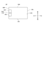
- FIG. 1 is a perspective view showing the configuration of an automated teller machine 1.
- the automatic teller machine 1 has an appearance formed by a box-shaped housing 2.
- the front surface of the housing 2 is provided with an operation display unit 3, a bill deposit / withdrawal port 4, a coin deposit / withdrawal port 5, a card inlet / outlet 6, and a passbook entry / exit 7.
- a banknote deposit / withdrawal machine 10 (FIG. 2) is provided to perform various processes related to the deposit / withdrawal of banknotes.
- a coin deposit / withdrawal machine (not shown) is provided to perform various processes related to coin deposit / withdrawal.
- the banknote deposit / withdrawal machine 10 will be described in detail in Section A-2.
- the automated teller machine 1 has a main control unit (not shown) and a bill control unit (not shown).
- the main control unit is composed of a processor (not shown) such as a CPU (Central Processing Unit) and a storage unit (not shown) such as a ROM (Read Only Memory), and the processor executes a predetermined program from the storage unit. By reading and executing, the operation of each part of the automatic cash deposit machine 1 is controlled.
- the bill control unit is composed of a processor such as a CPU (not shown) and a storage unit such as a ROM (not shown), and the processor reads a predetermined program from the storage unit and executes it to perform a bill deposit / withdrawal machine. The operation of each part of 10 is controlled.
- the operation display unit 3 integrates an LCD (Liquid Crystal Display) and a touch panel that accepts operations by the user, and displays a menu screen to the user so that the user can perform operations related to transactions and input a personal identification number. Make it possible to enter the amount of money.
- LCD Liquid Crystal Display
- the bill deposit / withdrawal port 4 is an opening for the user to insert bills.
- the coin deposit / withdrawal port 5 is an opening for the user to insert coins.
- the card entrance / exit 6 is a part where various cards such as a cash card are inserted and ejected.
- a card processing unit (not shown) for reading the account number and the like magnetically recorded on various cards is provided on the back side of the card inlet / outlet 6.
- the passbook entrance / exit 7 is a part where the passbook is inserted and discharged. Behind the passbook entrance / exit 7, there is provided a passbook processing unit (not shown) that reads magnetic information from the magnetic recording unit provided in the passbook and records the contents of transactions in the passbook.
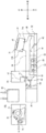
- FIG. 2 is a side view showing the internal configuration of the banknote deposit / withdrawal machine 10.
- the bill deposit / withdrawal machine 10 is roughly divided into a bill deposit / withdrawal machine frame 10F that constitutes the entire outer portion, an upper unit 10U that occupies the upper portion of the bill deposit / withdrawal machine frame 10F, and a bill deposit / withdrawal machine frame 10F. It is composed of a lower unit 10L that occupies a side portion.
- the upper unit 10U and the lower unit 10L are attached to the bill deposit / withdrawal machine frame 10F via slide rails (not shown) along the front-rear direction. Therefore, in the bill deposit / withdrawal machine 10, for example, in a state where the front door (not shown) of the housing 2 is opened, the user can use the bill deposit / withdrawal machine frame 10F to perform the upper unit 10U and the lower unit 10L, respectively. Can be pulled forward. Further, by pushing each of the upper unit 10U and the lower unit 10L pulled out forward by the user to the rear, each of the upper unit 10U and the lower unit 10L can be stored in the bill deposit / withdrawal machine frame 10F.
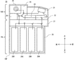
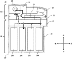
- FIGS. 3 and 4 are side views (1) showing the internal configuration of the upper unit 10U
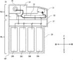
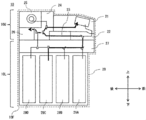
- FIG. 4 is a side view (2) showing the internal configuration of the upper unit 10U.
- the upper unit 10U is provided with a customer service unit 21, an upper front transport unit 22, a discrimination unit 23, an upper rear transport unit 24, a temporary hold unit 25, and a reject storage 26.
- the customer service unit 21 has a container 31 for accommodating banknotes to be inserted by the user at the time of deposit and banknotes to be handed to the user at the time of withdrawal.
- the upper end of the container 31 is an opening portion connected to the bill deposit / withdrawal port 4, and a movable shutter 32 for closing or opening the opening portion is provided in the customer service portion 21.
- the front end of the bottom of the container 31 is provided with an intake port 31a for taking in the banknotes inserted in the container 31, and the rear end of the bottom of the container 31 discharges the banknotes to the container 31.
- a discharge port 31b is provided for this purpose.
- the customer service unit 21 has a transport path 33 connecting the intake port 31a of the container 31 and the upper front transport section 22, and a transport path 34 connecting the discharge port 31b of the container 31 and the upper rear transport section 24. Have.
- the upper front transport unit 22 is located on the front lower side inside the upper unit 10U, and has a transport path 41 and a switching portion 42.
- the transport path 41 has a branch point P1 and is connected to the transport path 33 of the customer service unit 21, the discrimination unit 23, and the front portion of the lower unit 10L.
- the switching unit 42 is provided at the branching point P1, and transports the banknotes by connecting the transport path 33 of the customer service unit 21 and the discriminating unit 23 or the discriminating unit 23 and the front portion of the lower unit 10L. Switch to the route. Then, the upper front transport unit 22 transports banknotes by a transport roller (not shown) along the switched transport path.
- the discrimination unit 23 is located below the customer service unit 21 and behind the upper front transport unit 22, and has a discrimination transport path 51 and a discrimination sensor 52.
- the discrimination transport path 51 is connected to the upper front transport unit 22 and the upper rear transport unit 24.
- the discrimination sensor 52 is arranged along the discrimination transport path 51, and for example, a magnetic sensor that reads the magnetism of the bill, an image sensor that reads the image of the bill, a thickness sensor that detects the thickness of the bill, and a running state of the bill are detected. It is a combination of running sensors and the like.
- the identification unit 23 sends various detection results obtained from the identification sensor 52 to the banknote control unit as banknote identification results.
- the bill control unit determines the denomination, authenticity, correct loss (whether or not it is damaged), etc. of the bill based on the discrimination result sent from the discrimination unit 23, and after recognizing the transport state, obtains the result. Based on the results obtained, the transport route and destination of banknotes are determined.
- the upper-rear transport unit 24 is located behind the customer service unit 21 and the discrimination unit 23, and has a transport path 61 and switching units 62, 63, and 64.
- the transport path 61 has branch points P2, P3, and P4, and is connected to the transport path 34 of the customer service unit 21, the discrimination unit 23, the temporary holding unit 25, the reject storage 26, and the rear portion of the lower unit 10L.
- the switching portions 62 to 64 are provided at the branching points P2 to P4, respectively, and the bill transport route is a transport route connecting the discriminating unit 23 and the temporary holding unit 25, and a transport path 34 of the discriminating unit 23 and the customer service unit 21.
- the upper-rear transport unit 24 transports banknotes by a transport roller (not shown) along the switched transport path.
- the temporary holding section 25 is a tape system in which banknotes are wound around the drum 71 together with the tape and stored.
- the drum 71 is rotated in the winding direction R1.
- the conveyed banknotes are wound around the peripheral side surface of the drum 71 together with the tape and stored.
- the temporary holding portion 25 rotates the drum 71 in the rewinding direction R2, which is the opposite direction to the bills being stored, while the reel 72 is rotated in the reel winding direction, which is the opposite direction to the bills being stored.
- the banknotes are peeled off together with the tape from the peripheral side surface of the drum 71, and the banknotes are delivered to the upper-rear transport unit 24. Further, the temporary holding portion 25 transitions between a state in which the temporary holding portion 25 is housed in the upper unit 10U by a slide rail (not shown) and a state in which the temporary holding portion 25 is pulled out rearward (in the direction of arrow A in FIG. 4) from the upper unit 10U.
- the reject storage 26 is a portion for storing rejected banknotes that are judged by the discrimination unit 23 to be severely damaged and should not be reused or withdrawn. When it arrives, the rejected banknotes are released into the internal storage space and stored. Further, the reject storage 26 is mounted on the mounting frame of the reject storage 26 (hereinafter, the reject storage mounting slot 81). The user can pull out the reject storage 26 from the reject storage mounting slot 81 by lifting the reject storage 26 upward (in the direction of the arrow U in FIG. 4) with the temporary holding portion 25 pulled backward from the upper unit 10U. .. Further, the user lowers the reject storage 26 downward (in the direction of arrow D in FIG.
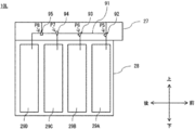
- FIG. 5 is a side view showing the internal configuration of the lower unit 10L.
- the lower unit 10L is provided with a lower transport portion 27 and a lower frame 28.
- the lower transport section 27 has a transport path 91 and switching sections 92, 93, 94 and 95.
- the transport path 91 has branch points P5, P6, P7 and P8, and is connected to the upper front transport unit 22, the upper rear transport unit 24 and the bill storage 29 (29A, 29B, 29C, 29D). ..
- the switching portions 92 to 95 are provided at the branching points P5 to P8, respectively, and the bill transport route is the transport route connecting the upper front transport unit 22 and any of the banknote storages 29A to 29D or the upper front transport unit 22.
- the transfer path is switched to connect the upper and rear transfer units 24. Then, the lower transport unit 27 transports banknotes by a transport roller (not shown) along the switched transport path.
- the lower frame 28 has a hollow rectangular parallelepiped shape with an open upper end, and four banknote storages 29 (29A, 29B, 29C, 29D) for storing reusable (recyclable) banknotes are arranged in the front-rear direction. Have been placed.
- the banknote storages 29 (29A to 29D) are all configured in the same manner, and have a rectangular parallelepiped shape that is long in the vertical direction.
- Each banknote storage 29 can store and pay out banknotes, and at the time of storing banknotes, the banknotes transported by the lower transport unit 27 are discharged and accumulated in the internal storage space.
- each banknote storage 29 separates the banknotes accumulated in the internal storage space one by one from the top and transports them upward when the banknotes are fed out, so that the banknotes are delivered to the lower transport unit 27. There is.
- the denomination of the banknote to be stored is set in advance.
- FIG. 6 is an explanatory diagram (1) for explaining the banknote transport route in the banknote deposit / withdrawal machine 10 at the time of deposit
- FIG. 7 is an explanatory diagram (1) for explaining the banknote transport path in the banknote deposit / withdrawal machine 10 at the time of deposit
- FIG. 8 is explanatory drawing (3) explaining the transport path of the banknote in the banknote deposit / withdrawal machine 10 at the time of deposit.
- the bill deposit / withdrawal machine 10 When the bill deposit / withdrawal machine 10 receives an operation instruction from the user to start the deposit transaction via the operation display unit 8, the bill deposit / withdrawal machine 10 starts the deposit counting process.
- the bill deposit / withdrawal machine 10 opens the shutter 32 of the customer service unit 21.
- the banknote deposit / withdrawal machine 10 closes the shutter 32 of the customer service unit 21 and then separates the banknotes in the container 31 one by one. It is transported to the discrimination unit 23 via the front transport unit 22.
- the banknote deposit / withdrawal machine 10 temporarily holds the banknotes that have been identified as normal banknotes from the identification unit 23 via the upper / rear transport unit 24, as shown in the solid line path of FIG.
- the banknote deposit / withdrawal machine 10 transports banknotes that have been identified as deposit-rejected banknotes whose discrimination result is not suitable for deposit, from the discrimination unit 23 to the upper / rear transport unit 24, as shown by the broken line path in FIG. It is returned to the user by returning to the container 31 of the customer service unit 21 via the road 34 and opening the shutter 32.
- the banknote deposit / withdrawal machine 10 completes the deposit counting process. After that, the banknote deposit / withdrawal machine 10 calculates the deposit amount based on the total result of the denomination and the number of banknotes taken in from the customer service unit 21, and displays a predetermined operation instruction screen on the operation display unit 8 to display the user. Present the deposit amount and let them choose whether to continue or cancel the deposit transaction.
- the banknote deposit / withdrawal machine 10 takes all the banknotes stored in the temporary holding unit 25 to the customer service unit via the upper / rear transport unit 24. After returning to the container 31 of 21, it is returned to the user by opening the shutter 32.
- the banknote deposit / withdrawal machine 10 starts the deposit storage process.
- the banknote deposit / withdrawal machine 10 sequentially pays out the banknotes (normal banknotes) stored in the temporary holding unit 25, and then conveys the money to the discrimination unit 23 via the upper / rear transfer unit 24. Differentiate species.
- the banknote deposit / withdrawal machine 10 corresponds to the denomination-identified banknotes sequentially from the discrimination unit 23 via the upper front transfer unit 22 and the lower transfer unit 27. It is transported to and stored in the banknote storage 29 (here, the banknote storage 29C).
- the discriminating section 23 to the upper front transport section 22, the lower transport section 27, and the upper rear transport section.
- the portions 24 are sequentially conveyed to the reject storage 26 for storage.
- FIG. 9 is an explanatory diagram illustrating a banknote transport route in the banknote deposit / withdrawal machine 10 at the time of withdrawal.
- the banknote deposit / withdrawal machine 10 starts the withdrawal process when it receives an operation instruction from the user to start the withdrawal transaction and to specify the withdrawal amount via the operation display unit 8.
- the banknote deposit / withdrawal machine 10 determines the denomination and the number of banknotes according to the withdrawal amount. Then, the banknote deposit / withdrawal machine 10 pays out one banknote from each banknote storage 29 according to the determined denomination and the number of banknotes, and then sequentially passes through the lower transport unit 27 and the upper front transport unit 22 to discriminate unit 23. Transport to.
- the banknote deposit / withdrawal machine 10 uses the customer service unit 21 from the identification unit 23 via the upper / rear transport unit 24, as shown in the solid line path of FIG. 9, for the banknotes that have been identified as normal banknotes. And accumulated in the container 31.
- the banknotes that have been identified as the withdrawal reject banknotes whose discrimination result is not suitable for withdrawal are sent from the discrimination unit 23 to the reject storage 26 via the upper / rear transport unit 24. Transport and store. Then, when the withdrawal amount of banknotes is accumulated in the container 31, the banknote deposit / withdrawal machine 10 opens the shutter 32 of the customer service unit 21 to allow the user to take out the banknotes accumulated in the container 31. .. The operation of the banknote deposit / withdrawal machine 10 at the time of withdrawal transaction is as described above.
- FIGS. 10 to 15 The configurations of the reject storage 26 and the reject storage mounting slot 81 will be described with reference to FIGS. 10 to 15.
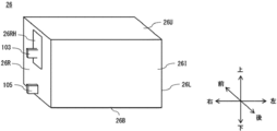
- 10 is a perspective view showing the configuration of the reject storage 26
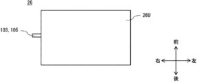
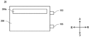
- FIG. 11 is a top view showing the configuration of the reject storage 26
- FIG. 12 is a front view showing the configuration of the reject storage 26.
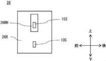
- 13 is a side view showing the configuration of the reject storage 26
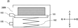
- FIG. 14 is a cross-sectional view showing the internal configuration of the reject storage 26
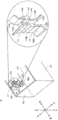
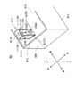
- FIG. 15 is a perspective view showing the configuration of the reject storage mounting slot 81. ..
- the reject storage 26 which is an example of the medium storage for storing the medium, includes a reject storage housing top plate 26U, a reject storage housing bottom plate 26B, a reject storage housing left plate 26L, a reject storage housing right plate 26R, and a reject storage housing. It is formed in a rectangular parallelepiped shape by the body front plate 26H and the reject storage housing rear surface plate 26I.
- the reject storage housing front plate 26H has a receiving port 26Ha so that bills sent from the upper / rear transport unit 24 to the inside of the reject storage 26 can be stored.
- the reject storage mounting slot 81 which is an example of a slot for holding the medium storage in the detachable direction, is the reject storage mounting slot left side wall 81L, the reject storage mounting slot right side wall 81R, the reject storage mounting portion 81B, and the reject storage mounting slot. It is formed by a frame consisting of a front wall (not shown) and a rear wall 81I of a reject storage mounting slot.
- the reject storage 26 can be attached to and detached from the reject storage mounting slot 81 along the attachment / detachment direction (vertical direction).
- the downward direction is the mounting direction which is one direction of the attachment / detachment direction
- the upper direction is the pulling direction which is the other direction of the attachment / detachment direction.
- the reject storage 26 is mounted in the reject storage mounting slot 81 by being lowered from the state of being gripped by the user in the mounting direction and placed on the reject storage mounting portion 81B.
- the reject storage 26 In the reject storage mounted state in which the reject storage 26 is mounted in the reject storage mounting slot 81, the reject storage 26 is connected to the delivery port (not shown) in the upper / rear transport unit 24 via the receiving port 26Ha. ..
- the reject storage 26 can receive the banknotes from the upper / rear transport unit 24.
- the reject storage 26 is pulled out from the reject storage mounting slot 81 by being lifted in the pulling direction from the state of being gripped by the user.
- a stage 101 for collecting banknotes is provided inside the reject storage 26, and a spring 102 is provided under the stage 101.
- the spring 102 is compressed and the stage 101 is gradually lowered.
- stage bottom state when the maximum number of banknotes are accumulated on the stage 101 and the stage 101 is at the lowest position (hereinafter referred to as the stage bottom state), no more banknotes can be accumulated on the stage 101. Therefore, it is necessary to detect the stage bottom state and stop the transfer of banknotes from the upper / rear transfer unit 24 to the reject storage 26.
- a protrusion-shaped stage bottom detection detector 103 which is an example of a light-shielding member, is provided on the right side surface of the stage 101. The stage bottom detection detector 103 protrudes from the hole 26RH provided in the right side plate 26R of the reject storage housing.
- the reject storage mounting slot 81 is provided with a stage bottom detection sensor 104 including an optical light emitting sensor (not shown) and a light receiving sensor (not shown), which is an example of a light blocking detection sensor.
- the stage bottom detection sensor 104 has a U-shape having a light-shielding detection space 104S, which is an example of a light-shielding detection space in which an optical axis passes between the light-emitting sensor and the light-receiving sensor and light-shielding by a light-shielding member is detected. It has become.
- the stage bottom detection detector 103 is provided at a position (stage bottom position) that blocks the light-shielding detection space 104S of the stage bottom detection sensor 104 when the stage bottom state is reached.
- stage bottom position that blocks the light-shielding detection space 104S of the stage bottom detection sensor 104
- the transfer of banknotes from the upper-rear transfer unit 24 to the reject storage 26 stops.
- a protrusion-shaped mounting detection detector 105 which is an example of a light-shielding member, is provided near the bottom of the reject storage housing right side plate 26R. It is provided.
- a mounting detection sensor 106 including an optical light emitting sensor (not shown) and a light receiving sensor (not shown), which is an example of a light blocking detection sensor, is provided.
- the mounting detection sensor 106 has a U-shape having a light-shielding detection space 106S, which is an example of a light-shielding detection space in which an optical axis passes between the light-emitting sensor and the light-receiving sensor and light-shielding by a light-shielding member is detected. It has become.
- the mounting detection detector 105 is provided at a position that blocks the light-shielding detection space 106S of the mounting detection sensor 106 when the reject storage 26 is mounted in the reject storage mounting slot 81.
- stage bottom detection detector 103 and the mounting detection detector 105 are arranged in a straight line parallel to the attachment / detachment direction (vertical direction) with respect to the right side plate 26R of the reject storage housing.
- the stage bottom detection sensor 104 and the mounting detection sensor 106 are also arranged in a straight line parallel to the attachment / detachment direction (vertical direction) with respect to the right side wall 81R of the reject storage slot. Further, in order to facilitate attachment / detachment of the reject storage 26, a gap is formed between the reject storage 26 and the reject storage mounting slot 81 in the front-rear direction.
- the mounting detection detector 105 when the user mounts the reject storage 26 in the reject storage mounting slot 81, if the reject storage 26 is mounted at an angle in the front-rear direction, the mounting detection detector 105 is attached to the stage bottom detection sensor 104. There is a possibility that the stage bottom detection sensor 104 may fall off or be damaged due to a collision (see FIG. 20). Further, when the user pulls out the reject storage 26 from the reject storage mounting slot 81, if it is pulled out by tilting it in the front-rear direction, the mounting detection detector 105 collides with the stage bottom detection sensor 104, and the stage bottom detection sensor 104 May fall off or be damaged (see FIG. 21).
- a guide that guides the user to block the light-shielding detection space 104S of the stage bottom detection sensor 104 when the reject storage 26 is mounted by tilting the reject storage 26 in the reject storage mounting slot 81 in the front-rear direction An upper guide 111 is provided above the stage bottom detection sensor 104.
- the lower guide is an example of a guide that guides the mounting detection detector 105 to the light-shielding detection space 104S of the stage bottom detection sensor 104 when the user pulls out the reject storage 26 by tilting it in the front-rear direction from the reject storage mounting slot 81.
- 112 is provided below the stage bottom detection sensor 104.
- the upper guide 111 and the lower guide 112 are parts mounted in the reject storage mounting slot 81.
- the upper guide 111 is composed of a tapered portion 111A (first tapered portion 111A1, second tapered portion 111A2) and an extension portion 111B (first extension portion 111B1, second extension portion 111B2).
- the first tapered portion 111A1 is a tapered portion formed obliquely rearward from the upper side to the lower side, and the first extension portion 111B1 is attached / detached from the lower end to the lower side of the first tapered portion 111A1. It is a linear portion formed in the vertical direction).
- the second tapered portion 111A2 is a tapered portion formed obliquely forward from the upper side to the lower side, and the second extension portion 111B2 is attached / detached from the lower end of the second tapered portion 111A2 toward the lower side. It is a linear portion formed in the vertical direction).
- the lower guide 112 is composed of a tapered portion 112A (first tapered portion 112A1, second tapered portion 112A2) and an extension portion 112B (first extension portion 112B1, second extension portion 112B2).
- the first tapered portion 112A1 is a tapered portion formed obliquely rearward from the lower side to the upper side, and the first extension portion 112B1 is in the attachment / detachment direction (up and down) from the upper end of the first tapered portion 112A1 toward the upper side. It is a linear portion formed in the direction).
- the second tapered portion 112A2 is a tapered portion formed obliquely forward from the lower side to the upper side, and the second extension portion 112B2 is attached / detached (up and down) from the upper end of the second tapered portion 112A2 toward the upper side. It is a linear portion formed in the direction).
- the taper portion 111A contacts the mounting detection detector 105 to a position where the mounting detection detector 105 blocks the light-shielding detection space 104S of the stage bottom detection sensor 104.
- the extension portion 111B is an example of an extension portion for directing the mounting detection detector 105 guided by the tapered portion 111A in the attachment / detachment direction. ..
- the taper portion 112A is in contact with the mounting detection detector 105 to a position where the mounting detection detector 105 blocks the light-shielding detection space 104S of the stage bottom detection sensor 104. It is an example of a guide portion for guiding the mounting detection detector 105, and the extension portion 112B is an example of an extension portion for directing the mounting detection detector 105 guided by the tapered portion 112A in the attachment / detachment direction.
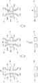
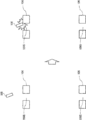
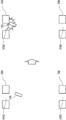
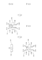
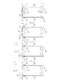
- FIG. 16 is an explanatory view for explaining the mounting state of the reject storage 26 (when mounted along the attachment / detachment direction)
- FIG. 17 is a mounting state of the reject storage 26 (when mounted tilted in the front-rear direction).
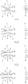
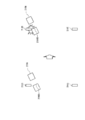
- FIG. 18 is an explanatory view for explaining the state of pulling out the reject storage 26 (when pulling out along the attachment / detachment direction)
- FIG. 19 is a state of pulling out the reject storage 26 (front-back direction).
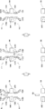
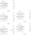
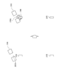
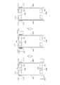
- FIG. 20 is an explanatory diagram for explaining the mounting state of the reject storage 26 (when mounted tilted in the front-rear direction), and FIG. 21 is a comparative example of mounting the reject storage 26.
- This is a comparative example for explaining the state of pulling out (when pulling out by tilting in the front-back direction). This time, it is assumed that the stage 101 is at the bottom position of the stage.
- the mounting detection detector 105 is for stage bottom detection. It passes through the light-shielding detection space 104S of the sensor 104. After that, the mounting detection detector 105 blocks the light-shielding detection space 106S of the mounting detection sensor 106 to complete the mounting of the reject storage 26. At this time, the stage bottom detection detector 103 blocks the light-shielding detection space 104S of the stage bottom detection sensor 104.
- the mounting detection detector 105 first uses the stage bottom detection sensor 104. After hitting the tapered portion 111A of the upper guide 111 provided above and guiding the mounting detection detector 105 to a position where it passes through the light-shielding detection space 104S of the stage bottom detection sensor 104, the extension portion 111B directs the direction in the attachment / detachment direction. be changed.
- the mounting detection detector 105 passes through the light-shielding detection space 104S of the stage bottom detection sensor 104, and then blocks the light-shielding detection space 106S of the mounting detection sensor 106 to complete the mounting of the reject storage 26.
- the stage bottom detection detector 103 blocks the light-shielding detection space 104S of the stage bottom detection sensor 104. In this way, when the user tries to mount the reject storage 26 in the reject storage mounting slot 81 by tilting it in the front-rear direction, the mounting detection detector 105 is used for stage bottom detection by the tapered portion 111A and the extension portion 111B of the upper guide 111.
- the mounting detection detector 105 collides with the stage bottom detection sensor 104 as in the comparative example in which the upper guide 111 shown in FIG. 20 is not provided. Can be prevented.
- the mounting detection detector 105 is the stage bottom detection sensor 104.
- the reject storage 26 is pulled out while passing through the light-shielding detection space 104S.
- the mounting detection detector 105 is below the stage bottom detection sensor 104.
- the mounting detection detector 105 is guided to a position where it passes through the light-shielding detection space 104S of the stage bottom detection sensor 104, and then is turned in the attachment / detachment direction by the extension portion 112B. Be done. After that, the reject storage 26 is pulled out while the mounting detection detector 105 passes through the light-shielding detection space 104S of the stage bottom detection sensor 104.
- the mounting detection detector 105 is subjected to the stage bottom detection sensor by the tapered portion 112A and the extension portion 112B of the lower guide 112. Since the guide is guided to pass through the light-shielding detection space 104S of 104, the mounting detection detector 105 collides with the stage bottom detection sensor 104 as in the comparative example in which the lower guide 112 shown in FIG. 21 is not provided. Can be prevented.
- the upper guide 111 is provided above the stage bottom detection sensor 104 in the reject storage mounting slot 81.
- the upper guide 111 has a tapered portion 111A and an extension portion 111B, and the tapered portion 111A is a detector for mounting detection when the user tries to mount the reject storage 26 in the reject storage mounting slot 81 by tilting it in the front-rear direction.
- the mounting detection detector 105 is guided while contacting the mounting detection detector 105 to a position where the 105 passes through the light-shielding detection space 104S of the stage bottom detection sensor 104.
- the extension portion 111B sets the orientation of the mounting detection detector 105 guided by the taper portion 111A to the attachment / detachment direction.
- the mounting detection detector 105 in the reject storage 26 is the stage bottom detection sensor 104 in the reject storage mounting slot 81. It is possible to prevent the stage bottom detection sensor 104 from falling off or being damaged due to a collision with the stage bottom detection sensor 104.
- a lower guide 112 is provided below the stage bottom detection sensor 104 in the reject storage mounting slot 81.
- the lower guide 112 has a tapered portion 112A and an extension portion 112B, and the tapered portion 112A is a detector 105 for mounting detection when the user tries to pull out the reject storage 26 from the reject storage mounting slot 81 by tilting it in the front-rear direction.
- the extension portion 112B sets the direction of the mounting detection detector 105 guided by the taper portion 112A to the attachment / detachment direction.
- the mounting detection detector 105 in the reject storage 26 becomes the stage bottom detection sensor 104 in the reject storage mounting slot 81. It is possible to prevent the stage bottom detection sensor 104 from falling off or being damaged due to a collision.
- ⁇ B Second embodiment>
- the configurations of the reject storage 226 and the reject storage mounting slot 281 are different from those of the first embodiment, and the other aspects are the same as those of the first embodiment.
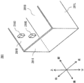
- FIG. 22 is a side view showing the configuration of the reject storage 226, and FIG. 23 is a perspective view showing the configuration of the reject storage mounting slot 281.
- the reject storage 226 includes a reject storage housing top plate 226U, a reject storage housing bottom plate 226B, a reject storage housing left plate (not shown), a reject storage housing right plate 226R, a reject storage housing front plate 226H, and a reject storage. It is formed in a rectangular parallelepiped shape by the housing rear surface plate 226I.
- the reject storage housing front plate 226H has a receiving port (not shown) so that bills sent from the upper / rear transport unit 24 to the inside of the reject storage 26 can be stored.
- the reject storage slot 281 includes a reject storage mounting slot left side wall 281L, a reject storage mounting slot right side wall 281R, a reject storage mounting portion 281B, a reject storage mounting slot front wall (not shown), and a reject storage mounting slot rear wall 281I. It is formed by a frame.
- the arrangement relationship between the detector and the sensor is opposite to that in the first embodiment.
- the reject storage 226 has a stage bottom detection sensor 2104 and a mounting detection sensor 2106
- the reject storage mounting slot 281 has a stage bottom detection detector 2103 and a mounting detection detector 2105. ..
- the stage bottom detection sensor 2104 and the mounting detection sensor 2106 are arranged in a straight line parallel to the attachment / detachment direction (vertical direction) with respect to the reject storage housing right side plate 226R, and the shape is the stage bottom detection sensor. This is the same as the 104 and the mounting detection sensor 106.
- the stage bottom detection detector 2103 and the mounting detection detector 2105 are also arranged in a straight line parallel to the attachment / detachment direction (vertical direction) with respect to the right side wall 281R of the reject storage slot, and the shape is the stage bottom detection detector 103. And the same as the detector 105 for mounting detection.
- an upper guide 2111 is provided above the mounting detection sensor 2106.
- the upper guide 2111 guides the mounting detection sensor 2106 so that the stage bottom detection detector 2103 passes through the light-shielding detection space 2106S when the reject storage 226 is tilted and pulled out from the reject storage mounting slot 281 in the front-rear direction.
- a lower guide 2112 is provided below the mounting detection sensor 2106. The lower guide 2112 guides the mounting detection sensor 2106 so that the stage bottom detection detector 2103 passes through the light-shielding detection space 2106S when the reject storage 226 is mounted in the reject storage mounting slot 281 at an angle in the front-rear direction.
- the upper guide 2111 is composed of a tapered portion 2111A (first tapered portion 2111A1, second tapered portion 2111A2) and an extension portion 2111B (first extension portion 2111B1, second extension portion 2111B2).
- the first tapered portion 2111A1 is a tapered portion formed diagonally backward from the upper side to the lower side, and the first extension portion 2111B1 is attached / detached (up and down) from the lower end of the first tapered portion 2111A1 toward the lower side. It is a linear portion formed in the direction).
- the second taper portion 2111A2 is a tapered portion formed obliquely forward from the upper side to the lower side, and the second extension portion 2111B2 is in the attachment / detachment direction (from the lower end of the second taper portion 2111A2 to the lower side). It is a linear portion formed in the vertical direction).
- the lower guide 2112 is composed of a tapered portion 2112A (first tapered portion 2112A1, second tapered portion 2112A2) and an extension portion 2112B (first extension portion 2112B1, second extension portion 2112B2).
- the first tapered portion 2112A1 is a tapered portion formed obliquely rearward from the lower side to the upper side, and the first extension portion 2112B1 is in the attachment / detachment direction (up and down) from the upper end of the first tapered portion 2112A1 toward the upper side. It is a linear portion formed in the direction).
- the second tapered portion 2112A2 is a tapered portion formed obliquely forward from the lower side to the upper side, and the second extension portion 2112B2 is in the attachment / detachment direction (vertical direction) from the upper end of the second tapered portion 2112A2 toward the upper side. It is a linear portion formed in.
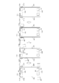
- FIG. 24 is an explanatory view for explaining the mounting state of the reject storage 226 (when mounted along the attachment / detachment direction)
- FIG. 25 is a mounting state of the reject storage 226 (when mounted tilted in the front-rear direction).
- 26 is an explanatory view for explaining the state of pulling out the reject storage 226 (when pulling out along the attachment / detachment direction)
- FIG. 27 is a state of pulling out the reject storage 226 (front-back direction).
- FIG. 28 is an explanatory diagram for explaining the mounting state of the reject storage 226 (when mounted tilted in the front-rear direction)
- FIG. 29 is a comparative example of mounting the reject storage 226. This is a comparative example for explaining the state of pulling out (when pulling out by tilting in the front-back direction).
- the light-shielding detection space 2106S of the mounting detection sensor 2106 is the stage bottom. It passes through the detection detector 2103. After that, the mounting detection sensor 2106 completes mounting of the reject storage 226 when the mounting detection detector 2105 reaches a position where it blocks the light-shielding detection space 2106S. At this time, the stage bottom detection sensor 2104 has reached a position where the stage bottom detection detector 2103 blocks the light blocking detection space 2104S.
- the stage bottom detection detector 2103 hits the tapered portion 2112A of the above, and the mounting detection sensor 2106 is guided to a position where the stage bottom detection detector 2103 passes through the light-shielding detection space 2106S of the mounting detection sensor 2106, and then the extension portion 2112B. Can be turned in the direction of attachment / detachment.
- the mounting detection sensor 2106 After that, after the stage bottom detection detector 2103 passes through the light-shielding detection space 2106S, the mounting detection sensor 2106 reaches a position where the light-shielding detection space 2106S is blocked by the mounting detection detector 2105, thereby completing the mounting of the reject storage 226. do. At this time, the stage bottom detection detector 2103 blocks the light-shielding detection space 2104S of the stage bottom detection sensor 2104. In this way, when the user tries to mount the reject storage 226 in the reject storage mounting slot 281 by tilting it in the front-rear direction, the mounting detection sensor 2106 is guided to the tapered portion 2112A and the extension portion 2112B of the lower guide 2112. It is possible to prevent the stage bottom detection detector 2103 from colliding with the mounting detection sensor 2106 as in the comparative example in which the lower guide 2112 shown in FIG. 28 is not provided.
- the light-shielding detection space 2106S of the mounting detection sensor 2106 is set on the stage bottom.
- the reject storage 226 is pulled out while allowing the detection detector 2103 to pass through.
- the stage bottom detection detector 2103 is provided above the mounting detection sensor 2106. After the mounting detection sensor 2106 is guided so as to hit the tapered portion 2111A of the upper guide 2111 and the stage bottom detection detector 2103 passes through the light-shielding detection space 2106S of the mounting detection sensor 2106, the extension portion 2111B moves in the attachment / detachment direction. It is pulled out while being turned around.
- the mounting detection sensor 2106 is guided to the tapered portion 2111A and the extension portion 2111B of the upper guide 2111. It is possible to prevent the stage bottom detection detector 2103 from colliding with the mounting detection sensor 2106 as in the comparative example in which the upper guide 2111 shown in FIG. 29 is not provided.
- the lower guide 2112 is provided below the mounting detection sensor 2106 in the reject storage 226.
- the lower guide 2112 has a tapered portion 2112A and an extension portion 2112B, and the tapered portion 2112A is for detecting the stage bottom when the user tries to mount the reject storage 226 in the reject storage mounting slot 281 by tilting it in the front-rear direction.
- the mounting detection sensor 2106 is guided to a position where the detector 2103 passes through the shading detection space 2106S.
- the stage bottom detection detector 2103 in the reject storage mounting slot 281 becomes the mounting detection sensor 2106 in the reject storage 226. It is possible to prevent the mounting detection sensor 2106 from falling off or being damaged due to a collision.
- the upper guide 2111 is provided above the mounting detection sensor 2106 in the reject storage 226.
- the upper guide 2111 has a tapered portion 2111A and an extension portion 2111B, and the tapered portion 2111A is for detecting the stage bottom when the user tries to pull out the reject storage 226 from the reject storage mounting slot 281 by tilting it in the front-rear direction.
- the mounting detection sensor 2106 is guided to a position where the detector 2103 passes through the shading detection space 2106S.
- the stage bottom detection detector 2103 in the reject storage mounting slot 281 becomes the mounting detection sensor 2106 in the reject storage 226. It is possible to prevent the mounting detection sensor 2106 from falling off or being damaged due to a collision.
- ⁇ C Third embodiment>
- the configurations of the reject storage 326 and the reject storage mounting slot 381 are different from those of the first embodiment, and the other aspects are the same as those of the first embodiment.
- FIGS. 30 to 32 The configurations of the reject storage 326 and the reject storage mounting slot 381 will be described with reference to FIGS. 30 to 32.
- 30 is a side view showing the configuration of the reject storage 326
- FIG. 31 is a bottom view showing the configuration of the reject storage 326
- FIG. 32 is a perspective view showing the configuration of the reject storage slot 381. be.
- the reject storage 326 includes a reject storage housing top plate 326U, a reject storage housing bottom plate 326B, a reject storage housing left plate 326L, a reject storage housing right plate 326R, a reject storage housing front plate 326H, and a reject storage housing rear surface plate. It is constructed in a rectangular parallelepiped shape by 326I.
- the reject storage housing front plate 326H has a receiving port (not shown) so that bills sent from the upper / rear transport unit 24 to the inside of the reject storage 26 can be stored.
- the reject storage slot 381 includes a reject storage mounting slot left side wall 381L, a reject storage mounting slot right side wall 381R, a reject storage mounting portion 381B, a reject storage mounting slot front wall (not shown), and a reject storage mounting slot rear wall 381I. It is formed by a frame.
- the stage bottom detection detector 3103 and the mounting detection detector 3105 are provided on the right side plate 326R of the reject storage housing in the reject storage 326 in a straight line parallel to the attachment / detachment direction (vertical direction). Is the same as the stage bottom detection detector 103 and the mounting detection detector 105.
- the stage bottom detection detector 3103 and The mounting detection detector 3105 is provided in a space (rejection storage housing right plate recess 326V) formed by denting a part of the surface of the reject storage housing right plate 326R from the lower end to the upper side toward the left. ing.
- the right end surface of the stage bottom detection detector 3103 and the mounting detection detector 3105 is flush with the right end plate 326R of the reject storage housing, and the stage bottom detection detector 3103 and the mounting detection detector 3105 are the reject storage. Prevent it from popping out from the right side plate 326R of the housing.
- the inner side surface portion 326M is formed from the reject storage housing right plate 326R toward the left end (bottom surface) of the reject storage housing right plate recess 326V. .. Further, an edge portion 326E is formed at the lower end of the inner side surface portion 326M.
- the stage bottom detection sensor 3104 having the same configuration as the stage bottom detection sensor 104 is provided at a position corresponding to the stage bottom position on the right side wall 381R of the reject storage slot.
- a mounting detection sensor 3106 having the same configuration as the mounting detection sensor 106 is provided near the bottom of the right side wall 381R of the reject storage mounting slot.
- the sensor cover 3111 is provided above the stage bottom detection sensor 3104.
- the sensor cover 3111 is a component mounted in the reject storage mounting slot 381.
- the sensor cover 3111 is tilted in the front-rear direction by the tapered portion 3111B described later guiding the edge portion 326E of the reject storage 326, so that the detector 3105 for mounting detection is installed when the reject storage 326 is mounted in the reject storage mounting slot 381. It indirectly guides the stage bottom detection sensor 3104 to the light-shielding detection space 3104S.
- the sensor cover 3111 is composed of an upper surface portion 3111A, a tapered portion 3111B (first tapered portion 3111B1, second tapered portion 3111B2) and an extension portion 3111C (first extension portion 3111C1, second extension portion 3111C2).
- the first tapered portion 3111B1 is a tapered portion formed obliquely forward from the front end portion of the upper surface portion 3111A toward the lower side, and the first extension portion 3111C1 faces downward from the lower end of the first tapered portion 3111B1. It is a linear portion formed in the attachment / detachment direction (vertical direction).
- the second tapered portion 3111B2 is a tapered portion formed obliquely rearward from the rear end portion of the upper surface portion 3111A, and the second extension portion 3111C2 is directed downward from the lower end of the second tapered portion 3111B2. It is a linear portion formed in the attachment / detachment direction (vertical direction).
- the upper surface portion 3111A prevents the mounting detection detector 3105 from coming into contact with the upper surface of the stage bottom detection sensor 3104 when the user mounts the reject storage 326 in the reject storage mounting slot 381.
- the tapered portion 3111B guides the edge portion 326E on the bottom surface of the reject storage 326.
- the reject storage 326 is tilted in the front-rear direction while the mounting detection detector 3105 is blocking the light-shielding detection space 3104S of the stage bottom detection sensor 3104, so that the edge portion 326E is the stage bottom detection sensor 3104. Prevent contact with the sides of the.
- the first protruding wall 381RT1 is provided near the inside of the first extension portion 3111C1 of the sensor cover 3111 along the attachment / detachment direction.
- a second protruding wall 381RT2 is provided near the inside of the second extension portion 3111C2 of the sensor cover 3111 along the attachment / detachment direction.
- the first protruding wall 381RT1 and the second protruding wall 381RT2 are collectively referred to as a protruding wall 381RT.
- the edge portion 326E of the reject storage 326 is tilted in the front-rear direction until the mounting detection detector 3105 passes through the stage bottom detection sensor 3104. Regulate not to. This prevents the user from tilting the reject storage 326 from the reject storage mounting slot 381 in the front-rear direction and pulling it out.
- FIG. 33 is an explanatory view for explaining the mounting state of the reject storage 326 (when mounted along the attachment / detachment direction)
- FIG. 34 is a mounting state of the reject storage 326 (when mounted tilted in the front-rear direction).
- 35 is an explanatory view for explaining the state of pulling out the reject storage 326 (when pulling out along the attachment / detachment direction)
- FIG. 36 is a state of pulling out the reject storage 326 (front-back direction). It is explanatory drawing explaining (at the time of pulling out).
- the mounting detection detector 3105 is for stage bottom detection. It passes through the shading detection space 3104S of the sensor 3104. After that, the mounting detection detector 3105 blocks the light-shielding detection space 3106S of the mounting detection sensor 3106 to complete the mounting of the reject storage 326. At this time, the stage bottom detection detector 3103 blocks the light-shielding detection space 3104S of the stage bottom detection sensor 3104.
- the edge portion 326E of the reject storage 326 is the stage bottom detection sensor 3104. It hits the tapered portion 3111B of the sensor cover 3111 provided above the above, and after the mounting detection detector 3105 is indirectly guided to a position where it passes through the light-shielding detection space 3104S of the stage bottom detection sensor 3104, it is attached and detached by the extension portion 3111C. You can turn around.
- the mounting detection detector 3105 passes through the light-shielding detection space 3104S of the stage bottom detection sensor 3104, and then blocks the light-shielding detection space 3106S of the mounting detection sensor 3106 to complete the mounting of the reject storage 326.
- the stage bottom detection detector 3103 blocks the light-shielding detection space 3104S of the stage bottom detection sensor 3104.
- the mounting detection detector 3105 indirectly guides the reject storage 326 to the tapered portion 3111B and the extension portion 3111C of the sensor cover 3111. Therefore, it is possible to prevent the stage bottom detection detector 3103 from colliding with the stage bottom detection sensor 3104.
- the mounting detection detector 3105 is used for the stage bottom detection sensor 3104.
- the reject storage 326 is pulled out while passing through the light-shielding detection space 3104S.
- the edge portion 326E of the reject storage 326 hits the protruding wall 381RT and the mounting detection detector. Until the 3105 passes through the stage bottom detection sensor 3104, the edge portion 326E of the reject storage 326 continues to be regulated so as to be tilted in the front-rear direction and not move. Therefore, the reject storage 326 is pulled out along the attachment / detachment direction, and it is possible to prevent the stage bottom detection detector 3103 from colliding with the stage bottom detection sensor 3104.
- stage bottom detection detector 3103 and the mounting detection detector 3105 are provided in the recess 326V on the right side plate of the reject storage housing.
- the stage bottom detection detector 3103 and the mounting detection detector 3105 do not pop out from the right side plate 326R of the reject storage housing, so that it is possible to prevent the user from being injured by touching them. ..
- a cover 3111 is provided above the stage bottom detection sensor 3104 in the reject storage mounting slot 381.
- the cover 3111 has a tapered portion 3111B and an extension portion 3111C, and the tapered portion 3111B is a detector 3105 for mounting detection when the user tries to mount the reject storage 326 in the reject storage mounting slot 381 by tilting it in the front-rear direction. Indirectly guides the edge portion 326E formed in the recess 326V on the right side plate of the reject storage housing of the reject storage 326 to the position where the stage bottom detection sensor 3104 passes through the light-shielding detection space 3104S, thereby indirectly detecting the mounting of the detector 3105. To guide you.
- the extension portion 3111C indirectly changes the direction of the mounting detection detector 3105 guided by the taper portion 3111B to the attachment / detachment direction by changing the direction of the edge portion 326E to the attachment / detachment direction.
- the mounting detection detector 3105 in the reject storage 326 collides with the stage bottom detection sensor 3104 in the reject storage mounting slot 381. This can prevent the stage bottom detection sensor 3104 from falling off or being damaged.
- a protruding wall 381RT is provided along the attachment / detachment direction on the right side wall 381R of the reject storage slot 381 of the reject storage mounting slot 381.
- the protruding wall 381RT does not move with the edge portion 326E of the reject storage 326 tilted in the front-rear direction until the mounting detection detector 3105 passes through the stage bottom detection sensor 3104.
- the mounting detection detector 3105 in the reject storage 326 collides with the stage bottom detection sensor 3104 in the reject storage mounting slot 381. This can prevent the stage bottom detection sensor 3104 from falling off or being damaged.
- the upper guide 111 and the lower guide 112 are parts to be mounted in the reject storage mounting slot 81, but the upper guide 111 and the lower guide 112 are integrally molded in the reject storage mounting slot 81. You may. Further, in the second embodiment, the upper guide 2111 and the lower guide 2112 are parts to be attached to the reject storage 226, but even if the upper guide 2111 and the lower guide 2112 are integrally molded in the reject storage 226. good.
- the upper guide 111 (2111) and the lower guide 112 (2112) are provided with respect to the attachment / detachment direction of the stage bottom detection sensor 104 (2104).
- the sensor 106 (2106) may be provided in the attachment / detachment direction.
- both the upper guide 111 (2111) and the lower guide 112 (2112) are provided, but only one of them may be provided.
- the reject storage 26 and the reject storage mounting slot 81 have a plurality of light-shielding members (stage bottom detection detector 103 and mounting detection detector 105) and a plurality of light-shielding detection sensors (stage bottom detection sensor 104 and mounting).
- stage bottom detection detector 103 and mounting detection detector 105 stage bottom detection detector 103 and mounting detection detector 105
- stage bottom detection sensor 104 and mounting stage bottom detection sensor 104 and mounting
- the present invention is applied even if the reject storage 26 has a single light-shielding member and the reject storage mounting slot 81 has only a single light-shielding detection sensor. be able to.
- the reject storage 26 in the reject storage mounting slot 81 is detected by connecting a connector
- the reject storage 26 has a single stage bottom detection detector 103
- the reject storage mounting slot 81 is single. It is configured to have one stage bottom detection sensor 104.
- the present invention can be applied as a configuration having only a single light-shielding member and a single light-shielding
- the reject storage is taken as an example of the medium storage, but the present invention can also be applied to various medium storages such as a banknote storage.
- a banknote storage for example, it is an automatic cash deposit machine provided with a banknote storage for storing reusable (recyclable) banknotes and a banknote storage slot for mounting the banknote storage in the device so that it can be attached and detached in the detachable direction.
- the storage slot has a U-shaped light-shielding detection sensor having a light-shielding detection space that detects light-shielding when the banknote storage is in a predetermined state, and the banknote storage is in a predetermined state.
- the present invention can be applied as an automatic cash deposit machine having a guide for guiding the light-shielding member so that the light-shielding member does not collide with the light-shielding detection sensor when the banknote storage is attached / detached at an angle.
- the reject storage is taken as an example of the unit, but various units such as a discrimination unit and a temporary holding unit that realize a predetermined function of the device can also be used.
- the present invention can be applied.
- it is an automated teller machine equipped with a discriminating unit for discriminating banknotes and a discriminating unit mounting slot for mounting the discriminating unit in the device in a detachable direction, and the discriminating unit mounting slot is in a predetermined state.
- the banknote storage has a U-shaped light-shielding detection sensor having a light-shielding detection space that detects light-shielding when the bill storage is in a predetermined state, and the bill storage blocks the light-shielding detection space of the light-shielding detection sensor.
- a gap is formed between the bill storage and the bill storage mounting slot in a predetermined direction, and the bill storage is further tilted in the direction in which the gap is formed so that the bill storage can be attached and detached.
- the present invention can be applied as an automated teller machine having a guide for guiding the light-shielding member so that the light-shielding member does not collide with the light-shielding detection sensor.
- an automated teller machine is taken as an example of a medium handling device, but the present invention is applied to various medium handling devices such as a check deposit machine and a teller cashier. Can be done.
Landscapes
- Physics & Mathematics (AREA)
- General Physics & Mathematics (AREA)
- Pile Receivers (AREA)
Abstract
媒体取扱装置の媒体収納庫着脱時における遮光検知センサの保護性能を高める。媒体を収納する媒体収納庫と、媒体収納庫を着脱方向に着脱可能に装置内へ装着する媒体収納庫装着スロットと、を備える媒体取扱装置であって、媒体収納庫装着スロットは、媒体収納庫が所定の状態であるときに遮光を検知する遮光検知空間を有するコの字形状の遮光検知センサを備え、媒体収納庫は、媒体収納庫が所定の状態であるときに遮光検知センサの遮光検知空間を遮光するための遮光部材を備え、媒体収納庫と前記媒体収納庫装着スロットとの間に所定の方向に隙間が形成され、媒体収納庫装着スロットはさらに、隙間が形成された方向に傾けて媒体収納庫が着脱される際、遮光部材が遮光検知センサに衝突しないように遮光部材を案内するガイドを備える媒体取扱装置により、本課題を解決する。
Description
本発明は、媒体取扱装置に関する。
紙幣やカード等の媒体を取り扱う媒体取扱装置の一例に、紙幣の入出金処理を取り扱う現金自動預払機がある。現金自動預払機は、使用者との間で紙幣の授受を行う接客部、紙幣の金種及び真偽を鑑別する鑑別部、紙幣を一時的に保留する一時保留部、再利用(リサイクル)不能なリジェクト紙幣を収納するリジェクト庫、再利用(リサイクル)可能なリサイクル紙幣を収納する紙幣収納庫等の各種ユニットを有している。また、現金自動預払機は、リジェクト庫を装置内へ装着するためのリジェクト庫装着スロットを有しており、当該リジェクト庫装着スロットには、使用者がリジェクト庫に収納されているリジェクト紙幣を回収できるようにリジェクト庫を着脱方向に着脱可能にしているものがある(例えば、特許文献1参照)。さらに、リジェクト庫装着スロットには、コの字形状の遮光検知センサが設けられ、リジェクト庫には、当該遮光検知センサを遮る遮光部材が設けられているものがある。なお、遮光検知センサは、リジェクト庫の所定の状態を検知するためのセンサであり、例えば、リジェクト庫の内部にあるステージにリジェクト紙幣が最大枚数集積され、ステージが最も下がった状態であるステージボトム状態を検知するためのセンサや、リジェクト庫のリジェクト庫装着スロットへの装着を検知するためのセンサがある。また、遮光部材は、遮光検知センサを遮ることで遮光検知センサにリジェクト庫が所定の状態であることを検知させるための部材であり、例えば、ステージボトム状態を検知するための遮光検知センサを遮光する板状の部材や、リジェクト庫のリジェクト庫装着スロットへの装着を検知するための遮光検知センサを遮光する板状の部材である。
このような現金自動預払機においては、リジェクト庫の着脱を容易にするためにリジェクト庫とリジェクト庫装着スロットとで前後方向に関して隙間が形成されている場合がある。この場合、使用者がリジェクト庫をリジェクト庫装着スロットに装着する際、前後方向に傾けて装着すると、リジェクト庫の遮光部材がリジェクト庫装着スロットの遮光検知センサに衝突してしまい、当該遮光検知センサが脱落・破損してしまう可能性がある。また、使用者がリジェクト庫をリジェクト庫装着スロットから引き抜く際、前後方向に傾けて引き抜くと、リジェクト庫の遮光部材がリジェクト庫装着スロットの遮光検知センサに衝突してしまい、当該遮光検知センサが脱落・破損してしまう可能性がある。
そこで、使用者がリジェクト庫装着スロットに対してリジェクト庫を傾けて着脱する際、遮光検知センサの脱落や破損を防ぐことが求められている。
上記課題を解決するため、本発明の媒体取扱装置は、媒体を収納する媒体収納庫と、前記媒体収納庫を着脱方向に着脱可能に装置内へ装着する媒体収納庫装着スロットとを備え、前記媒体収納庫装着スロットは、前記媒体収納庫が所定の状態であるときに遮光を検知する遮光検知空間を有するコの字形状の遮光検知センサを備え、前記媒体収納庫は、前記媒体収納庫が前記所定の状態であるときに前記遮光検知センサの前記遮光検知空間を遮光するための遮光部材を備え、前記媒体収納庫と前記媒体収納庫装着スロットとの間に所定の方向に隙間が形成され、前記媒体収納庫装着スロットはさらに、前記隙間が形成された方向に傾けて前記媒体収納庫が着脱される際、前記遮光部材が前記遮光検知センサに衝突しないように前記遮光部材を案内するガイドを備える。
また、上記課題を解決するため、本発明の媒体取扱装置は、媒体を収納する媒体収納庫と、前記媒体収納庫を着脱方向に着脱可能に装置内へ装着する媒体収納庫装着スロットとを備え、前記媒体収納庫は、前記媒体収納庫が所定の状態であるときに遮光を検知する遮光検知空間を有するコの字形状の遮光検知センサを備え、前記媒体収納庫装着スロットは、前記媒体収納庫が前記所定の状態であるときに前記遮光検知センサの前記遮光検知空間を遮光するための遮光部材を備え、前記媒体収納庫と前記媒体収納庫装着スロットとの間に所定の方向に隙間が形成され、前記媒体収納庫はさらに、前記隙間が形成された方向に傾けて前記媒体収納庫が着脱される際、前記遮光部材が前記遮光検知センサに衝突しないように前記遮光検知センサを案内するガイドを備える。
また、上記課題を解決するため、本発明の媒体取扱装置は、ユニットと、前記ユニットを着脱方向に着脱可能に装置内へ装着するユニット装着スロットとを備え、前記ユニット装着スロットは、前記ユニットが所定の状態であるときに遮光を検知する遮光検知空間を有するコの字形状の遮光検知センサを備え、前記ユニットは、前記ユニットが前記所定の状態であるときに前記遮光検知センサの前記遮光検知空間を遮光するための遮光部材を備え、前記ユニットは、前記ユニットが前記所定の状態であるときに前記遮光検知センサの前記遮光検知空間を遮光するための遮光部材を備え、前記ユニット装着スロットはさらに、前記隙間が形成された方向に傾けて前記ユニットが着脱される際、前記遮光部材が前記遮光検知センサに衝突しないように前記遮光部材を案内するガイドを備える。
本発明によれば、媒体取扱装置の媒体収納庫着脱時における遮光検知センサの保護性能を高めることができる。
以下に添付図面を参照しながら、本発明の第1の実施形態、第2の実施形態、第3の実施形態及び他の実施形態について詳細に説明する。なお、本明細書及び図面において、同一の機能構成を有する構成要素については、同一の符号を付することにより重複説明を省略する。
<A:第1の実施形態>
<A-1:現金自動預払機の構成>
本発明の第1の実施形態における現金自動預払機(以下、現金自動預払機1)の構成について、図1を用いて説明する。なお、図1は、現金自動預払機1の構成を示す斜視図である。
<A-1:現金自動預払機の構成>
本発明の第1の実施形態における現金自動預払機(以下、現金自動預払機1)の構成について、図1を用いて説明する。なお、図1は、現金自動預払機1の構成を示す斜視図である。
現金自動預払機1は、箱状の筐体2によって外観を形成している。
筐体2の前面には、操作表示部3、紙幣入出金口4、硬貨入出金口5、カード入出口6及び通帳入出口7が設けられている。筐体2の内部には、紙幣の入出金に関する種々の処理を行う紙幣入出金機10(図2)が設けられている。また、筐体2の内部には、硬貨の入出金に関する種々の処理を行う硬貨入出金機(図示せず)が設けられている。なお、紙幣入出金機10については、A-2節で詳述する。
また、現金自動預払機1は、主制御部(図示せず)及び紙幣制御部(図示せず)を有する。主制御部は、CPU(Central Processing Unit)等のプロセッサ(図示せず)及びROM(Read Only Memory)等の記憶部(図示せず)から構成され、当該プロセッサが当該記憶部から所定のプログラムを読み出して実行することにより現金自動預払機1の各部の動作の制御を実現する。紙幣制御部は、CPU等のプロセッサ(図示せず)及びROM等の記憶部(図示せず)から構成され、当該プロセッサが当該記憶部から所定のプログラムを読み出して実行することにより紙幣入出金機10の各部の動作の制御を実現する。
操作表示部3は、LCD(Liquid Crystal Display)と使用者による操作を受け付けるタッチパネルとが一体化されており、メニュー画面を使用者に表示して使用者が取引等に関する操作や暗証番号の入力や金額の入力等を行えるようにする。
紙幣入出金口4は、使用者が紙幣を投入するための開口部分である。
硬貨入出金口5は、使用者が硬貨を投入するための開口部分である。
カード入出口6は、キャッシュカード等の各種カードが挿入及び排出される部分である。カード入出口6の奥側には、各種カードに磁気記録された口座番号等の読み取りを行うカード処理部(図示せず)が設けられている。
通帳入出口7は、通帳が挿入及び排出される部分である。通帳入出口7の奥側には、通帳に設けられた磁気記録部から磁気情報を読み取ったり通帳に取引の内容を記録したりする通帳処理部(図示せず)が設けられている。
<A-2:紙幣入出金機の構成>
紙幣入出金機10の構成について、図2を用いて説明する。なお、図2は、紙幣入出金機10の内部構成を示す側面図である。
紙幣入出金機10の構成について、図2を用いて説明する。なお、図2は、紙幣入出金機10の内部構成を示す側面図である。
紙幣入出金機10は、大きく分けて、全体の外側部分を構成する紙幣入出金機フレーム10Fと、紙幣入出金機フレーム10Fの上側部分を占める上部ユニット10Uと、紙幣入出金機フレーム10Fの下側部分を占める下部ユニット10Lとにより構成されている。
上部ユニット10U及び下部ユニット10Lは、この紙幣入出金機フレーム10Fに対し、それぞれ前後方向に沿ったスライドレール(図示せず)を介して取り付けられている。このため、紙幣入出金機10は、例えば、筐体2の前扉(図示せず)が開放された状態において、使用者が紙幣入出金機フレーム10Fから上部ユニット10U及び下部ユニット10Lのそれぞれを前方へ引き出すことができる。また、使用者が前方へ引き出した上部ユニット10U及び下部ユニット10Lのそれぞれを後方へ押し込むことにより、上部ユニット10U及び下部ユニット10Lのそれぞれを紙幣入出金機フレーム10F内に格納することができる。
<A-2-1:上部ユニットの構成>
上部ユニット10Uの構成について、図3及び図4を用いて説明する。なお、図3は、上部ユニット10Uの内部構成を示す側面図(1)であり、図4は、上部ユニット10Uの内部構成を示す側面図(2)である。
上部ユニット10Uの構成について、図3及び図4を用いて説明する。なお、図3は、上部ユニット10Uの内部構成を示す側面図(1)であり、図4は、上部ユニット10Uの内部構成を示す側面図(2)である。
上部ユニット10Uには、接客部21、上前搬送部22、鑑別部23、上後搬送部24、一時保留部25及びリジェクト庫26が設けられている。
接客部21は、入金時に使用者が投入する紙幣や出金時に使用者に渡す紙幣を収容する収容器31を有している。収容器31の上端は紙幣入出金口4と繋がる開口部分となっており、当該開口部分を閉塞又は開放する可動式のシャッタ32が接客部21に設けられている。また、収容器31の底部の前端には収容器31に投入された紙幣を取り込むための取込口31aが設けられており、収容器31の底部の後端には収容器31へ紙幣を放出する為の放出口31bが設けられている。また、接客部21は、収容器31の取込口31aと上前搬送部22とを繋ぐ搬送路33と、収容器31の放出口31bと上後搬送部24とを繋ぐ搬送路34とを有している。
上前搬送部22は、上部ユニット10U内部の前下側に位置しており、搬送路41及び切替部42を有している。搬送路41は、分岐箇所P1を有しており、接客部21の搬送路33、鑑別部23及び下部ユニット10Lの前部と接続されている。切替部42は、分岐箇所P1に設けられており、紙幣の搬送経路を、接客部21の搬送路33と鑑別部23とを繋ぐ搬送経路又は鑑別部23と下部ユニット10Lの前部を繋ぐ搬送経路に切り替える。そして、上前搬送部22は、切り替えた搬送経路に沿って搬送ローラ(図示せず)により紙幣を搬送する。
鑑別部23は、接客部21の下方且つ上前搬送部22の後方に位置しており、鑑別搬送路51及び鑑別用センサ52を有している。鑑別搬送路51は、上前搬送部22及び上後搬送部24と接続されている。鑑別用センサ52は、鑑別搬送路51に沿って配置されており、例えば紙幣の磁気を読み取る磁気センサ、紙幣の画像を読み取るイメージセンサ、紙幣の厚みを検知する厚みセンサ及び紙幣の走行状態を検知する走行センサ等を組み合せたものとなっている。鑑別部23は、鑑別用センサ52から得られる種々の検知結果を紙幣の鑑別結果として紙幣制御部へ送る。紙幣制御部は、鑑別部23から送られてくる鑑別結果をもとに紙幣の金種、真偽、正損(損傷しているか否か)等を判断すると共に搬送状態を認識した後、得られた結果を基に紙幣の搬送経路や搬送先を決定するようになっている。
上後搬送部24は、接客部21及び鑑別部23の後方に位置しており、搬送路61並びに切替部62、63及び64を有している。搬送路61は、分岐箇所P2、P3及びP4を有しており、接客部21の搬送路34、鑑別部23、一時保留部25、リジェクト庫26及び下部ユニット10Lの後部と接続されている。切替部62~64は、それぞれ分岐箇所P2~P4に設けられており、紙幣の搬送経路を、鑑別部23と一時保留部25とを繋ぐ搬送経路、鑑別部23と接客部21の搬送路34とを繋ぐ搬送経路、鑑別部23とリジェクト庫26とを繋ぐ搬送経路又は下部ユニット10Lの後部とリジェクト庫26とを繋ぐ搬送経路に切り替える。そして、上後搬送部24は、切り替えた搬送経路に沿って搬送ローラ(図示せず)により紙幣を搬送する。
一時保留部25は、紙幣をテープと共にドラム71に巻き付けるようにして収納するテープ方式であり、上後搬送部24から紙幣が搬送されてくると、ドラム71を巻取方向R1に回転させる一方でリール72をリール巻戻方向r1に回転させることで、搬送されてきた紙幣をテープと共にドラム71の周側面に巻き付けて収納する。また、一時保留部25は、紙幣を繰り出す場合、ドラム71を紙幣収納時とは逆方向である巻戻方向R2に回転させる一方でリール72を紙幣収納時とは逆方向であるリール巻取方向r2に回転させることで、ドラム71の周側面からテープと共に紙幣を引き剥がし、当該紙幣を上後搬送部24に引き渡すようになっている。また、一時保留部25は、スライドレール(図示せず)によって上部ユニット10U内に収納された状態と、上部ユニット10Uから後方(図4矢印Aの方向)へ引き出された状態とに遷移する。
リジェクト庫26は、例えば鑑別部23で損傷の程度が大きく再利用や出金をすべきで無いと判断されたリジェクト紙幣を収納する部分であり、上後搬送部24からリジェクト紙幣が搬送されてくると当該リジェクト紙幣を内部の収納空間へ放出して収納する。また、リジェクト庫26は、リジェクト庫26の装着用フレーム(以下、リジェクト庫装着スロット81)に装着される。使用者は、一時保留部25を上部ユニット10Uから後方へ引き出した状態でリジェクト庫26を上方(図4矢印Uの方向)へ持ち上げることでリジェクト庫26をリジェクト庫装着スロット81から引き抜くことができる。また、使用者は、一時保留部25を上部ユニット10Uから後方に引き出した状態でリジェクト庫装着スロット81の上方からリジェクト庫26を下方(図4矢印Dの方向)へ降ろすことでリジェクト庫26をリジェクト庫装着スロット81に装着することができる。なお、リジェクト庫26及びリジェクト庫装着スロット81の構造については、A-5節で詳述する。リジェクト庫26の着脱については、A-6節で詳述する。
<A-2-2:下部ユニットの構成>
下部ユニット10Lの構成について、図5を用いて説明する。なお、図5は、下部ユニット10Lの内部構成を示す側面図である。
下部ユニット10Lの構成について、図5を用いて説明する。なお、図5は、下部ユニット10Lの内部構成を示す側面図である。
下部ユニット10Lには、下搬送部27及び下部フレーム28が設けられている。
下搬送部27は、搬送路91並びに切替部92、93、94及び95を有している。搬送路91は、分岐箇所P5、P6、P7及びP8を有しており、上前搬送部22、上後搬送部24及び紙幣収納庫29(29A、29B、29C、29D)と接続されている。切替部92~95は、それぞれ分岐箇所P5~P8に設けられており、紙幣の搬送経路を上前搬送部22と紙幣収納庫29A~29Dのいずれかとを繋ぐ搬送経路又は上前搬送部22と上後搬送部24とを繋ぐ搬送経路に切り替える。そして、下搬送部27は、切り替えた搬送経路に沿って搬送ローラ(図示せず)により紙幣を搬送するようになっている。
下部フレーム28は、上端が開放された中空の直方体状であり、内部に再利用(リサイクル)可能な紙幣を収納する4つの紙幣収納庫29(29A、29B、29C、29D)が前後方向に並べて配置されている。紙幣収納庫29(29A~29D)は、何れも同様に構成されており、上下方向に長い直方体状となっている。各紙幣収納庫29は、紙幣の収納及び繰り出しが可能であり、紙幣収納時には、下搬送部27により搬送されてきた紙幣を内部の収納空間に放出して集積する。また、各紙幣収納庫29は、紙幣繰り出し時には、内部の収納空間に集積されている紙幣を上から1枚ずつに分離して上方へと搬送することで下搬送部27に引き渡すようになっている。なお、各紙幣収納庫29は、それぞれ収納すべき紙幣の金種が予め設定されている。
<A-3:入金取引時の動作>
紙幣入出金機10における入金取引時の動作について、図6乃至図8を用いて説明する。なお、図6は、入金時の紙幣入出金機10における紙幣の搬送経路を説明する説明図(1)であり、図7は、入金時の紙幣入出金機10における紙幣の搬送経路を説明する説明図(2)であり、図8は、入金時の紙幣入出金機10における紙幣の搬送経路を説明する説明図(3)である。
紙幣入出金機10における入金取引時の動作について、図6乃至図8を用いて説明する。なお、図6は、入金時の紙幣入出金機10における紙幣の搬送経路を説明する説明図(1)であり、図7は、入金時の紙幣入出金機10における紙幣の搬送経路を説明する説明図(2)であり、図8は、入金時の紙幣入出金機10における紙幣の搬送経路を説明する説明図(3)である。
紙幣入出金機10は、操作表示部8を介して使用者から入金取引を開始する旨の操作指示を受け付けると、入金計数処理を開始する。入金計数処理が開始されると、紙幣入出金機10は、接客部21のシャッタ32を開く。その後、紙幣入出金機10は、使用者により収容器31内へ紙幣が投入されると、接客部21のシャッタ32を閉じた後、収容器31内の紙幣を1枚ずつに分離して上前搬送部22を介して鑑別部23へ搬送する。ここで、紙幣入出金機10は、鑑別結果が正常紙幣であると鑑別された紙幣については、図6の実線経路に示すように、鑑別部23から上後搬送部24を介して一時保留部25へ搬送して収納する。一方、紙幣入出金機10は、鑑別結果が入金に適さない入金リジェクト紙幣であると鑑別された紙幣については、図6の破線経路に示すように、鑑別部23から上後搬送部24、搬送路34を介して接客部21の収容器31に戻してシャッタ32を開くことで使用者に返却する。
入金リジェクト紙幣が発生することなく全ての紙幣の一時保留部16への搬送が終わると、又は入金リジェクト紙幣の返却が終わると、紙幣入出金機10は、入金計数処理を完了する。その後、紙幣入出金機10は、接客部21から取り込んだ紙幣の金種及び枚数の集計結果を基に入金額を算出すると共に、所定の操作指示画面を操作表示部8に表示させ、使用者に入金額を提示すると共に入金取引を継続するか中止するかを選択させる。
使用者により入金取引の中止が選択された場合、図7に示すように、紙幣入出金機10は、一時保留部25に収納している全ての紙幣を上後搬送部24を介して接客部21の収容器31へ戻した後、シャッタ32を開くことで使用者に返却する。
使用者により入金取引の継続が選択された場合、紙幣入出金機10は、入金収納処理を開始する。入金収納処理を開始すると、紙幣入出金機10は、一時保留部25に収納している紙幣(正常紙幣)を順次繰り出した後、上後搬送部24を介して鑑別部23へ搬送して金種を鑑別する。そして紙幣入出金機10は、図8の実線経路に示すように、金種が鑑別された紙幣を鑑別部23から上前搬送部22及び下搬送部27を順次介してその金種に対応する紙幣収納庫29(ここでは、紙幣収納庫29Cとする)へ搬送して収納する。
一方、図8の破線経路に示すように、鑑別結果が再利用不可能なリジェクト紙幣であると鑑別された紙幣については、鑑別部23から上前搬送部22、下搬送部27及び上後搬送部24を順次介してリジェクト庫26へ搬送して収納する。一時保留部25に収納されている全ての紙幣を収納し終えると、紙幣入出金機10は、この入金収納処理を終了する。紙幣入出金機10における入金取引時の動作は、以上のようになっている。
<A-4:出金取引時の動作>
紙幣入出金機10における出金取引時の動作について、図9を用いて説明する。なお、図9は、出金時の紙幣入出金機10における紙幣の搬送経路を説明する説明図である。
紙幣入出金機10における出金取引時の動作について、図9を用いて説明する。なお、図9は、出金時の紙幣入出金機10における紙幣の搬送経路を説明する説明図である。
紙幣入出金機10は、操作表示部8を介して使用者から出金取引を開始する旨及び出金額を指定する旨の操作指示を受け付けると、出金処理を開始する。出金処理を開始すると、紙幣入出金機10は、出金額に応じた紙幣の金種及び枚数を決定する。そして、紙幣入出金機10は、決定した金種及び枚数に応じて各紙幣収納庫29から紙幣を1枚ずつ繰り出した後、下搬送部27及び上前搬送部22を順次介して鑑別部23へ搬送する。ここで、紙幣入出金機10は、鑑別結果が正常紙幣であると鑑別された紙幣については、図9の実線経路に示すように、鑑別部23から上後搬送部24を介して接客部21へ搬送して収容器31内に集積する。
一方、図9の破線経路に示すように、鑑別結果が出金に適さない出金リジェクト紙幣であると鑑別された紙幣については、鑑別部23から上後搬送部24を介してリジェクト庫26へ搬送して収納する。そして、紙幣入出金機10は、出金額分の紙幣が収容器31内に集積されると、接客部21のシャッタ32を開くことで収容器31内に集積された紙幣を使用者に取り出させる。紙幣入出金機10における出金取引時の動作は、以上のようになっている。
<A-5:リジェクト庫及びリジェクト庫装着スロットの構成>
リジェクト庫26及びリジェクト庫装着スロット81の構成について、図10乃至図15を用いて説明する。なお、図10は、リジェクト庫26の構成を示す斜視図であり、図11は、リジェクト庫26の構成を示す上面図であり、図12は、リジェクト庫26の構成を示す正面図であり、図13は、リジェクト庫26の構成を示す側面図であり、図14は、リジェクト庫26の内部構成を示す断面図であり、図15は、リジェクト庫装着スロット81の構成を示す斜視図である。
リジェクト庫26及びリジェクト庫装着スロット81の構成について、図10乃至図15を用いて説明する。なお、図10は、リジェクト庫26の構成を示す斜視図であり、図11は、リジェクト庫26の構成を示す上面図であり、図12は、リジェクト庫26の構成を示す正面図であり、図13は、リジェクト庫26の構成を示す側面図であり、図14は、リジェクト庫26の内部構成を示す断面図であり、図15は、リジェクト庫装着スロット81の構成を示す斜視図である。
媒体を収納する媒体収納庫の一例であるリジェクト庫26は、リジェクト庫筐体天板26U、リジェクト庫筐体底板26B、リジェクト庫筐体左側板26L、リジェクト庫筐体右側板26R、リジェクト庫筐体前面板26H及びリジェクト庫筐体後面板26Iによって直方体状に構成されている。なお、リジェクト庫筐体前面板26Hは、上後搬送部24からリジェクト庫26の内部に送られてきた紙幣を収納できるよう、受取口26Haを有している。
媒体収納庫を着脱方向に着脱可能に保持するスロットの一例であるリジェクト庫装着スロット81は、リジェクト庫装着スロット左側壁81L、リジェクト庫装着スロット右側壁81R、リジェクト庫装着部81B、リジェクト庫装着スロット前面壁(図示せず)及びリジェクト庫装着スロット後面壁81Iから成るフレームによって形成されている。
リジェクト庫26は、リジェクト庫装着スロット81に対し着脱方向(上下方向)に沿って着脱可能である。なお、ここでは、下方向を着脱方向の一方向である装着方向、上方向を着脱方向の他方向である引抜方向とする。リジェクト庫26は、使用者に把持された状態から装着方向に降ろされてリジェクト庫装着部81Bに載置されることにより、リジェクト庫装着スロット81に装着される。リジェクト庫26がリジェクト庫装着スロット81に装着された状態であるリジェクト庫装着状態において、リジェクト庫26は、受取口26Haを介して上後搬送部24における引渡口(図示せず)と連結される。これにより、リジェクト庫26は、上後搬送部24から紙幣を受け取ることができる。一方、リジェクト庫26は、使用者に把持された状態から引抜方向に向かって持ち上げられることにより、リジェクト庫装着スロット81から引き抜かれる。
リジェクト庫26の内部には、紙幣を集積するためのステージ101が設けられており、ステージ101の下には、スプリング102が設けられている。ステージ101に紙幣が集積されると、スプリング102が圧縮され、ステージ101が徐々に下に下がってゆく。
ここで、ステージ101に紙幣が最大枚数集積され、ステージ101が最も下がった状態(以下、ステージボトム状態と称する)では、それ以上ステージ101に紙幣を集積させることができない。そのため、ステージボトム状態を検知して上後搬送部24からリジェクト庫26への紙幣の搬送を止める必要がある。ステージボトム状態の検知のため、ステージ101の右側面には、遮光部材の一例である突起形状のステージボトム検知用ディテクタ103が設けられている。なお、ステージボトム検知用ディテクタ103はリジェクト庫筐体右側板26Rに設けられた孔26RHから突出している。
リジェクト庫装着スロット81には、遮光検知センサの一例である、光学式の発光センサ(図示せず)及び受光センサ(図示せず)から成るステージボトム検知用センサ104が設けられている。ステージボトム検知用センサ104は、当該発光センサと受光センサとの間の光軸が通っており、遮光部材による遮光が検知される遮光検知空間の一例である遮光検知空間104Sを有するコの字形状となっている。ステージボトム検知用ディテクタ103は、ステージボトム状態になるとステージボトム検知用センサ104の遮光検知空間104Sを遮る位置(ステージボトム位置)に設けられている。ステージボトム検知用ディテクタ103がステージボトム検知用センサ104の遮光検知空間104Sを遮ると、上後搬送部24からリジェクト庫26への紙幣の搬送が止まる。
また、リジェクト庫26がリジェクト庫装着スロット81に正しく装着されていることを検知するために、リジェクト庫筐体右側板26Rの底部近傍に遮光部材の一例である突起形状の装着検知用ディテクタ105が設けられている。
リジェクト庫装着スロット81の底部には、遮光検知センサの一例である、光学式の発光センサ(図示せず)及び受光センサ(図示せず)から成る装着検知用センサ106が設けられている。装着検知用センサ106は、当該発光センサと受光センサとの間の光軸が通っており、遮光部材による遮光が検知される遮光検知空間の一例である遮光検知空間106Sを有するコの字形状となっている。装着検知用ディテクタ105は、リジェクト庫26がリジェクト庫装着スロット81に装着されると装着検知用センサ106の遮光検知空間106Sを遮る位置に設けられている。
ここで、ステージボトム検知用ディテクタ103及び装着検知用ディテクタ105は、リジェクト庫筐体右側板26Rに対して着脱方向(上下方向)と平行に一直線上に配置されている。ステージボトム検知用センサ104及び装着検知用センサ106についても、リジェクト庫装着スロット右側壁81Rに対して着脱方向(上下方向)と平行に一直線上に配置されている。また、リジェクト庫26の着脱を容易にするためにリジェクト庫26とリジェクト庫装着スロット81とで前後方向に関して隙間が形成されている。そのため、A-6節で詳述するが、使用者がリジェクト庫26をリジェクト庫装着スロット81に装着する際、前後方向に傾けて装着すると、装着検知用ディテクタ105がステージボトム検知用センサ104に衝突してしまい、ステージボトム検知用センサ104が脱落・破損してしまう可能性がある(図20参照)。また、使用者がリジェクト庫26をリジェクト庫装着スロット81から引き抜く際、前後方向に傾けて引き抜くと、装着検知用ディテクタ105がステージボトム検知用センサ104に衝突してしまい、ステージボトム検知用センサ104が脱落・破損してしまう可能性がある(図21参照)。
そこで、使用者がリジェクト庫26をリジェクト庫装着スロット81へ前後方向に傾けて装着する際に装着検知用ディテクタ105をステージボトム検知用センサ104の遮光検知空間104Sを遮るよう案内するガイドの一例である上ガイド111がステージボトム検知用センサ104の上方に設けられている。一方、使用者がリジェクト庫26をリジェクト庫装着スロット81から前後方向に傾けて引き抜く際に装着検知用ディテクタ105をステージボトム検知用センサ104の遮光検知空間104Sに案内するガイドの一例である下ガイド112がステージボトム検知用センサ104の下方に設けられている。なお、上ガイド111及び下ガイド112は、リジェクト庫装着スロット81に取り付けられた部品である。
上ガイド111は、テーパ部111A(第1テーパ部111A1、第2テーパ部111A2)及び延長部111B(第1延長部111B1、第2延長部111B2)から構成される。第1テーパ部111A1は、上側から下側に向けて後方へ斜めに形成されたテーパ形状部分であり、第1延長部111B1は、第1テーパ部111A1の下端から下側に向けて着脱方向(上下方向)に形成された直線形状部分である。第2テーパ部111A2は、上側から下側に向けて前方へ斜めに形成されたテーパ形状部分であり、第2延長部111B2は、第2テーパ部111A2の下端から下側に向けて着脱方向(上下方向)に形成された直線形状部分である。
下ガイド112は、テーパ部112A(第1テーパ部112A1、第2テーパ部112A2)及び延長部112B(第1延長部112B1、第2延長部112B2)から構成される。第1テーパ部112A1は、下側から上側に向けて後方へ斜めに形成されたテーパ形状部分であり、第1延長部112B1は、第1テーパ部112A1の上端から上側に向けて着脱方向(上下方向)に形成された直線形状部分である。第2テーパ部112A2は、下側から上側に向けて前方へ斜めに形成されたテーパ形状部分であり、第2延長部112B2は、第2テーパ部112A2の上端から上側に向けて着脱方向(上下方向)に形成された直線形状部分である。
なお、テーパ部111Aは、前後方向に傾けてリジェクト庫26が装着される際、装着検知用ディテクタ105がステージボトム検知用センサ104の遮光検知空間104Sを遮る位置まで装着検知用ディテクタ105に当接しながら装着検知用ディテクタ105を案内するための案内部の一例であり、延長部111Bは、テーパ部111Aに案内された装着検知用ディテクタ105の向きを着脱方向にするための延長部の一例である。また、テーパ部112Aは、前後方向に傾けてリジェクト庫26が引き抜かれる際、装着検知用ディテクタ105がステージボトム検知用センサ104の遮光検知空間104Sを遮る位置まで装着検知用ディテクタ105に当接しながら装着検知用ディテクタ105を案内するための案内部の一例であり、延長部112Bは、テーパ部112Aに案内された装着検知用ディテクタ105の向きを着脱方向にするための延長部の一例である。
<A-6:リジェクト庫の着脱>
リジェクト庫26の着脱について、図16乃至図21を用いて説明する。なお、図16は、リジェクト庫26の装着の様子(着脱方向に沿って装着時)を説明する説明図であり、図17は、リジェクト庫26の装着の様子(前後方向に傾けて装着時)を説明する説明図であり、図18は、リジェクト庫26の引抜の様子(着脱方向に沿って引抜時)を説明する説明図であり、図19は、リジェクト庫26の引抜の様子(前後方向に傾けて引抜時)を説明する説明図であり、図20は、リジェクト庫26の装着の様子(前後方向に傾けて装着時)を説明する比較例であり、図21は、リジェクト庫26の引抜の様子(前後方向に傾けて引抜時)を説明する比較例である。なお、今回、ステージ101はステージボトム位置にあると仮定する。
リジェクト庫26の着脱について、図16乃至図21を用いて説明する。なお、図16は、リジェクト庫26の装着の様子(着脱方向に沿って装着時)を説明する説明図であり、図17は、リジェクト庫26の装着の様子(前後方向に傾けて装着時)を説明する説明図であり、図18は、リジェクト庫26の引抜の様子(着脱方向に沿って引抜時)を説明する説明図であり、図19は、リジェクト庫26の引抜の様子(前後方向に傾けて引抜時)を説明する説明図であり、図20は、リジェクト庫26の装着の様子(前後方向に傾けて装着時)を説明する比較例であり、図21は、リジェクト庫26の引抜の様子(前後方向に傾けて引抜時)を説明する比較例である。なお、今回、ステージ101はステージボトム位置にあると仮定する。
図16に示すように、使用者がリジェクト庫26をリジェクト庫装着スロット81に装着する際、着脱方向(上下方向)に沿って装着した場合は、まず、装着検知用ディテクタ105はステージボトム検知用センサ104の遮光検知空間104Sを通過する。その後、装着検知用ディテクタ105は装着検知用センサ106の遮光検知空間106Sを遮ることでリジェクト庫26の装着が完了する。このとき、ステージボトム検知用ディテクタ103はステージボトム検知用センサ104の遮光検知空間104Sを遮っている。
図17に示すように、使用者がリジェクト庫26をリジェクト庫装着スロット81に装着する際、前後方向に傾けて装着した場合は、まず、装着検知用ディテクタ105は、ステージボトム検知用センサ104の上方に設けられた上ガイド111のテーパ部111Aに当たり、装着検知用ディテクタ105がステージボトム検知用センサ104の遮光検知空間104Sを通過する位置まで案内された後、延長部111Bによって着脱方向に向きを変えられる。その後、装着検知用ディテクタ105はステージボトム検知用センサ104の遮光検知空間104Sを通過した後、装着検知用センサ106の遮光検知空間106Sを遮ることでリジェクト庫26の装着が完了する。このとき、ステージボトム検知用ディテクタ103はステージボトム検知用センサ104の遮光検知空間104Sを遮っている。このように、使用者がリジェクト庫26を前後方向に傾けてリジェクト庫装着スロット81に装着しようとした場合、装着検知用ディテクタ105が上ガイド111のテーパ部111A及び延長部111Bによってステージボトム検知用センサ104の遮光検知空間104Sを通過するように案内されるため、図20に示す上ガイド111が設けられていない比較例のように装着検知用ディテクタ105がステージボトム検知用センサ104に衝突することを防ぐことができる。
図18に示すように、使用者がリジェクト庫26をリジェクト庫装着スロット81から引き抜く際、着脱方向(上下方向)に沿って引き抜いた場合は、装着検知用ディテクタ105がステージボトム検知用センサ104の遮光検知空間104Sを通過しながらリジェクト庫26が引き抜かれる。
図19に示すように、使用者がリジェクト庫26をリジェクト庫装着スロット81から引き抜く際、前後方向に傾けて引き抜いた場合は、まず、装着検知用ディテクタ105は、ステージボトム検知用センサ104の下方に設けられた下ガイド112のテーパ部112Aに当たり、装着検知用ディテクタ105がステージボトム検知用センサ104の遮光検知空間104Sを通過する位置まで案内された後、延長部112Bによって着脱方向に向きを変えられる。その後、装着検知用ディテクタ105がステージボトム検知用センサ104の遮光検知空間104Sを通過しながらリジェクト庫26が引き抜かれる。このように、使用者がリジェクト庫26を前後方向に傾けてリジェクト庫装着スロット81から引き抜こうとした場合、装着検知用ディテクタ105が下ガイド112のテーパ部112A及び延長部112Bによってステージボトム検知用センサ104の遮光検知空間104Sを通過するように案内されるため、図21に示す下ガイド112が設けられていない比較例のように装着検知用ディテクタ105がステージボトム検知用センサ104に衝突することを防ぐことができる。
<A-7:まとめ>
以上のように、第1の実施形態では、リジェクト庫装着スロット81におけるステージボトム検知用センサ104の上方に上ガイド111を設けた。上ガイド111はテーパ部111A及び延長部111Bを有しており、テーパ部111Aは、使用者がリジェクト庫26をリジェクト庫装着スロット81に前後方向に傾けて装着しようとした際に装着検知用ディテクタ105がステージボトム検知用センサ104の遮光検知空間104Sを通過する位置まで装着検知用ディテクタ105に当接しながら装着検知用ディテクタ105を案内する。延長部111Bは、テーパ部111Aに案内された装着検知用ディテクタ105の向きを着脱方向にする。これにより、使用者がリジェクト庫26をリジェクト庫装着スロット81に前後方向に傾けて装着しようとした場合でも、リジェクト庫26における装着検知用ディテクタ105がリジェクト庫装着スロット81におけるステージボトム検知用センサ104に衝突してしまい、ステージボトム検知用センサ104の脱落や破損を引き起こしてしまうことを防ぐことができる。
以上のように、第1の実施形態では、リジェクト庫装着スロット81におけるステージボトム検知用センサ104の上方に上ガイド111を設けた。上ガイド111はテーパ部111A及び延長部111Bを有しており、テーパ部111Aは、使用者がリジェクト庫26をリジェクト庫装着スロット81に前後方向に傾けて装着しようとした際に装着検知用ディテクタ105がステージボトム検知用センサ104の遮光検知空間104Sを通過する位置まで装着検知用ディテクタ105に当接しながら装着検知用ディテクタ105を案内する。延長部111Bは、テーパ部111Aに案内された装着検知用ディテクタ105の向きを着脱方向にする。これにより、使用者がリジェクト庫26をリジェクト庫装着スロット81に前後方向に傾けて装着しようとした場合でも、リジェクト庫26における装着検知用ディテクタ105がリジェクト庫装着スロット81におけるステージボトム検知用センサ104に衝突してしまい、ステージボトム検知用センサ104の脱落や破損を引き起こしてしまうことを防ぐことができる。
また、リジェクト庫装着スロット81におけるステージボトム検知用センサ104の下方に下ガイド112を設けた。下ガイド112はテーパ部112A及び延長部112Bを有しており、テーパ部112Aは、使用者がリジェクト庫26を前後方向に傾けてリジェクト庫装着スロット81から引き抜こうとした際に装着検知用ディテクタ105がステージボトム検知用センサ104の遮光検知空間104Sを通過する位置まで装着検知用ディテクタ105に当接しながら装着検知用ディテクタ105を案内する。延長部112Bは、テーパ部112Aに案内された装着検知用ディテクタ105の向きを着脱方向にする。これにより、使用者がリジェクト庫26を前後方向に傾けてリジェクト庫装着スロット81から引き抜こうとした場合でも、リジェクト庫26における装着検知用ディテクタ105がリジェクト庫装着スロット81におけるステージボトム検知用センサ104に衝突してしまい、ステージボトム検知用センサ104の脱落や破損を引き起こしてしまうことを防ぐことができる。
<B:第2の実施形態>
第2の実施形態では、リジェクト庫226及びリジェクト庫装着スロット281の構成が第1の実施形態と異なっており、その他は第1の実施形態と同様である。
第2の実施形態では、リジェクト庫226及びリジェクト庫装着スロット281の構成が第1の実施形態と異なっており、その他は第1の実施形態と同様である。
<B-1:リジェクト庫及びリジェクト庫装着スロットの構成>
リジェクト庫226及びリジェクト庫装着スロット281の構成について、図22及び図23を用いて説明する。なお、図22は、リジェクト庫226の構成を示す側面図であり、図23は、リジェクト庫装着スロット281の構成を示す斜視図である。
リジェクト庫226及びリジェクト庫装着スロット281の構成について、図22及び図23を用いて説明する。なお、図22は、リジェクト庫226の構成を示す側面図であり、図23は、リジェクト庫装着スロット281の構成を示す斜視図である。
リジェクト庫226は、リジェクト庫筐体天板226U、リジェクト庫筐体底板226B、リジェクト庫筐体左側板(図示せず)、リジェクト庫筐体右側板226R、リジェクト庫筐体前面板226H及びリジェクト庫筐体後面板226Iによって直方体状に構成されている。なお、リジェクト庫筐体前面板226Hは、上後搬送部24からリジェクト庫26の内部に送られてきた紙幣を収納できるよう、受取口(図示せず)を有している。
リジェクト庫装着スロット281は、リジェクト庫装着スロット左側壁281L、リジェクト庫装着スロット右側壁281R、リジェクト庫装着部281B、リジェクト庫装着スロット前面壁(図示せず)及びリジェクト庫装着スロット後面壁281Iから成るフレームよって形成されている。
第2の実施形態では、ディテクタとセンサの配置関係が第1の実施形態と逆になっている。具体的には、リジェクト庫226は、ステージボトム検知用センサ2104及び装着検知用センサ2106を有し、リジェクト庫装着スロット281は、ステージボトム検知用ディテクタ2103及び装着検知用ディテクタ2105を有している。なお、ステージボトム検知用センサ2104及び装着検知用センサ2106は、リジェクト庫筐体右側板226Rに対して着脱方向(上下方向)と平行に一直線上に配置されており、形状はステージボトム検知用センサ104及び装着検知用センサ106と同様である。ステージボトム検知用ディテクタ2103及び装着検知用ディテクタ2105についても、リジェクト庫装着スロット右側壁281Rに対して着脱方向(上下方向)と平行に一直線上に配置されており、形状はステージボトム検知用ディテクタ103及び装着検知用ディテクタ105と同様である。
また、装着検知用センサ2106の上方には、上ガイド2111が設けられている。上ガイド2111は、リジェクト庫226がリジェクト庫装着スロット281から前後方向に傾けて引き抜かれる際、ステージボトム検知用ディテクタ2103が遮光検知空間2106Sを通過するよう装着検知用センサ2106を案内する。一方、装着検知用センサ2106の下方には、下ガイド2112が設けられている。下ガイド2112は、リジェクト庫226がリジェクト庫装着スロット281に前後方向に傾けて装着される際、ステージボトム検知用ディテクタ2103が遮光検知空間2106Sを通過するよう装着検知用センサ2106を案内する。
上ガイド2111は、テーパ部2111A(第1テーパ部2111A1、第2テーパ部2111A2)及び延長部2111B(第1延長部2111B1、第2延長部2111B2)から構成される。第1テーパ部2111A1は、上側から下側に向けて後ろ斜めに形成されたテーパ形状部分であり、第1延長部2111B1は、第1テーパ部2111A1の下端から下側に向けて着脱方向(上下方向)に形成された直線形状部分である。第2テーパ部2111A2は、上側から下側に向けて前方へ斜めに形成されたテーパ形状部分であり、第2延長部2111B2は、第2テーパ部2111A2の下端から下側に向けて着脱方向(上下方向)に形成された直線形状部分である。
下ガイド2112は、テーパ部2112A(第1テーパ部2112A1、第2テーパ部2112A2)及び延長部2112B(第1延長部2112B1、第2延長部2112B2)から構成される。第1テーパ部2112A1は、下側から上側に向けて後方へ斜めに形成されたテーパ形状部分であり、第1延長部2112B1は、第1テーパ部2112A1の上端から上側に向けて着脱方向(上下方向)に形成された直線形状部分である。第2テーパ部2112A2は下側から上側に向けて前方へ斜めに形成されたテーパ形状部分であり、第2延長部2112B2は第2テーパ部2112A2の上端から上側に向けて着脱方向(上下方向)に形成された直線形状部分である。
<B-2:リジェクト庫の着脱>
リジェクト庫226の着脱について、図24乃至図29を用いて説明する。なお、図24は、リジェクト庫226の装着の様子(着脱方向に沿って装着時)を説明する説明図であり、図25は、リジェクト庫226の装着の様子(前後方向に傾けて装着時)を説明する説明図であり、図26は、リジェクト庫226の引抜の様子(着脱方向に沿って引抜時)を説明する説明図であり、図27は、リジェクト庫226の引抜の様子(前後方向に傾けて引抜時)を説明する説明図であり、図28は、リジェクト庫226の装着の様子(前後方向に傾けて装着時)を説明する比較例であり、図29は、リジェクト庫226の引抜の様子(前後方向に傾けて引抜時)を説明する比較例である。
リジェクト庫226の着脱について、図24乃至図29を用いて説明する。なお、図24は、リジェクト庫226の装着の様子(着脱方向に沿って装着時)を説明する説明図であり、図25は、リジェクト庫226の装着の様子(前後方向に傾けて装着時)を説明する説明図であり、図26は、リジェクト庫226の引抜の様子(着脱方向に沿って引抜時)を説明する説明図であり、図27は、リジェクト庫226の引抜の様子(前後方向に傾けて引抜時)を説明する説明図であり、図28は、リジェクト庫226の装着の様子(前後方向に傾けて装着時)を説明する比較例であり、図29は、リジェクト庫226の引抜の様子(前後方向に傾けて引抜時)を説明する比較例である。
図24に示すように、リジェクト庫226をリジェクト庫装着スロット281に装着する際、着脱方向(上下方向)に沿って装着した場合は、まず、装着検知用センサ2106の遮光検知空間2106Sがステージボトム検知用ディテクタ2103を通過する。その後、装着検知用センサ2106は装着検知用ディテクタ2105が遮光検知空間2106Sを遮る位置まで到達することでリジェクト庫226の装着が完了する。このとき、ステージボトム検知用センサ2104はステージボトム検知用ディテクタ2103が遮光検知空間2104Sを遮る位置まで到達している。
図25に示すように、使用者がリジェクト庫226をリジェクト庫装着スロット281に装着する際、前後方向に傾けて装着した場合は、まず、装着検知用センサ2106の下方に設けられた下ガイド2112のテーパ部2112Aにステージボトム検知用ディテクタ2103が当たり、ステージボトム検知用ディテクタ2103が装着検知用センサ2106の遮光検知空間2106Sを通過する位置まで装着検知用センサ2106は案内された後、延長部2112Bによって着脱方向に向きを変えられる。その後、装着検知用センサ2106は、遮光検知空間2106Sをステージボトム検知用ディテクタ2103が通過した後、遮光検知空間2106Sを装着検知用ディテクタ2105が遮る位置まで到達することでリジェクト庫226の装着が完了する。このとき、ステージボトム検知用ディテクタ2103はステージボトム検知用センサ2104の遮光検知空間2104Sを遮っている。このように、使用者がリジェクト庫226を前後方向に傾けてリジェクト庫装着スロット281に装着しようとした場合、装着検知用センサ2106が下ガイド2112のテーパ部2112A及び延長部2112Bに案内されるため、図28に示す下ガイド2112が設けられていない比較例のようにステージボトム検知用ディテクタ2103が装着検知用センサ2106に衝突することを防ぐことができる。
図26に示すように、使用者がリジェクト庫226をリジェクト庫装着スロット281から引き抜く際、着脱方向(上下方向)に沿って引き抜いた場合は、装着検知用センサ2106の遮光検知空間2106Sをステージボトム検知用ディテクタ2103が通過するようにしながらリジェクト庫226が引き抜かれる。
図27に示すように、使用者がリジェクト庫226をリジェクト庫装着スロット281から引き抜く際、前後方向に傾けて引き抜いた場合は、ステージボトム検知用ディテクタ2103は装着検知用センサ2106の上方に設けられた上ガイド2111のテーパ部2111Aに当たり、ステージボトム検知用ディテクタ2103が装着検知用センサ2106の遮光検知空間2106Sを通過するように装着検知用センサ2106は案内された後、延長部2111Bによって着脱方向に向きを変えられながら引き抜かれる。このように、使用者がリジェクト庫226を前後方向に傾けてリジェクト庫装着スロット281から引き抜こうとした場合、装着検知用センサ2106が上ガイド2111のテーパ部2111A及び延長部2111Bに案内されるため、図29に示す上ガイド2111が設けられていない比較例のようにステージボトム検知用ディテクタ2103が装着検知用センサ2106に衝突することを防ぐことができる。
<B-3:まとめ>
以上のように、第2の実施形態では、リジェクト庫226における装着検知用センサ2106の下方に下ガイド2112を設けた。下ガイド2112はテーパ部2112A及び延長部2112Bを有しており、テーパ部2112Aは、使用者がリジェクト庫226をリジェクト庫装着スロット281に前後方向に傾けて装着しようとした際にステージボトム検知用ディテクタ2103が遮光検知空間2106Sを通過する位置まで装着検知用センサ2106を案内する。これにより、使用者がリジェクト庫226をリジェクト庫装着スロット281に前後方向に傾けて装着しようした場合でも、リジェクト庫装着スロット281におけるステージボトム検知用ディテクタ2103がリジェクト庫226における装着検知用センサ2106に衝突してしまい、装着検知用センサ2106の脱落や破損を引き起こしてしまうことを防ぐことができる。
以上のように、第2の実施形態では、リジェクト庫226における装着検知用センサ2106の下方に下ガイド2112を設けた。下ガイド2112はテーパ部2112A及び延長部2112Bを有しており、テーパ部2112Aは、使用者がリジェクト庫226をリジェクト庫装着スロット281に前後方向に傾けて装着しようとした際にステージボトム検知用ディテクタ2103が遮光検知空間2106Sを通過する位置まで装着検知用センサ2106を案内する。これにより、使用者がリジェクト庫226をリジェクト庫装着スロット281に前後方向に傾けて装着しようした場合でも、リジェクト庫装着スロット281におけるステージボトム検知用ディテクタ2103がリジェクト庫226における装着検知用センサ2106に衝突してしまい、装着検知用センサ2106の脱落や破損を引き起こしてしまうことを防ぐことができる。
また、リジェクト庫226における装着検知用センサ2106の上方に上ガイド2111を設けた。上ガイド2111は、テーパ部2111A及び延長部2111Bを有しており、テーパ部2111Aは、使用者がリジェクト庫226をリジェクト庫装着スロット281から前後方向に傾けて引き抜こうとした際にステージボトム検知用ディテクタ2103が遮光検知空間2106Sを通過する位置まで装着検知用センサ2106を案内する。これにより、使用者がリジェクト庫226をリジェクト庫装着スロット281から前後方向に傾けて引き抜こうとした場合でも、リジェクト庫装着スロット281におけるステージボトム検知用ディテクタ2103がリジェクト庫226における装着検知用センサ2106に衝突してしまい、装着検知用センサ2106の脱落や破損を引き起こしてしまうことを防ぐことができる。
<C:第3の実施形態>
第3の実施形態では、リジェクト庫326及びリジェクト庫装着スロット381の構成が第1の実施形態と異なっており、その他は第1の実施形態と同様である。
第3の実施形態では、リジェクト庫326及びリジェクト庫装着スロット381の構成が第1の実施形態と異なっており、その他は第1の実施形態と同様である。
<C-1:リジェクト庫及びリジェクト庫装着スロットの構成>
リジェクト庫326及びリジェクト庫装着スロット381の構成について、図30乃至図32を用いて説明する。なお、図30は、リジェクト庫326の構成を示す側面図であり、図31は、リジェクト庫326の構成を示す下面図であり、図32は、リジェクト庫装着スロット381の構成を示す斜視図である。
リジェクト庫326及びリジェクト庫装着スロット381の構成について、図30乃至図32を用いて説明する。なお、図30は、リジェクト庫326の構成を示す側面図であり、図31は、リジェクト庫326の構成を示す下面図であり、図32は、リジェクト庫装着スロット381の構成を示す斜視図である。
リジェクト庫326は、リジェクト庫筐体天板326U、リジェクト庫筐体底板326B、リジェクト庫筐体左側板326L、リジェクト庫筐体右側板326R、リジェクト庫筐体前面板326H及びリジェクト庫筐体後面板326Iによって直方体状に構成されている。なお、リジェクト庫筐体前面板326Hは、上後搬送部24からリジェクト庫26の内部に送られてきた紙幣を収納できるよう、受取口(図示せず)を有している。
リジェクト庫装着スロット381は、リジェクト庫装着スロット左側壁381L、リジェクト庫装着スロット右側壁381R、リジェクト庫装着部381B、リジェクト庫装着スロット前面壁(図示せず)及びリジェクト庫装着スロット後面壁381Iから成るフレームよって形成されている。
第3の実施形態では、リジェクト庫326におけるリジェクト庫筐体右側板326Rにステージボトム検知用ディテクタ3103及び装着検知用ディテクタ3105が着脱方向(上下方向)と平行に一直線上に設けられており、形状はステージボトム検知用ディテクタ103及び装着検知用ディテクタ105と同様である。ただし、ステージボトム検知用ディテクタ3103及び装着検知用ディテクタ3105がリジェクト庫筐体右側板326Rから飛び出していることにより使用者が触れて怪我をしてしまうことを防ぐため、ステージボトム検知用ディテクタ3103及び装着検知用ディテクタ3105は、リジェクト庫筐体右側板326Rにおける下端から上方にかけての面の一部が左方向に向けて凹むことで形成された空間(リジェクト庫筐体右側板凹部326V)に設けられている。ここで、ステージボトム検知用ディテクタ3103及び装着検知用ディテクタ3105の右端面とリジェクト庫筐体右側板326Rとは面一になるようにし、ステージボトム検知用ディテクタ3103及び装着検知用ディテクタ3105がリジェクト庫筐体右側板326Rから飛び出さないようにする。また、リジェクト庫筐体右側板凹部326Vが形成されたことに伴い、リジェクト庫筐体右側板326Rからリジェクト庫筐体右側板凹部326Vの左端(底面)に向けて内側面部326Mが形成されている。さらに、内側面部326Mの下端にエッジ部326Eが形成されている。
また、第3の実施形態では、リジェクト庫装着スロット右側壁381Rにおいて、ステージボトム位置に対応する位置に、構成がステージボトム検知用センサ104と同様のステージボトム検知用センサ3104が設けられており、リジェクト庫装着スロット右側壁381Rの底部近傍に、構成が装着検知用センサ106と同様の装着検知用センサ3106が設けられている。
さらに、第3の実施形態では、ステージボトム検知用センサ3104の上方にセンサカバー3111が設けられている。センサカバー3111はリジェクト庫装着スロット381に取り付けられた部品である。センサカバー3111は、後述するテーパ部3111Bがリジェクト庫326のエッジ部326Eを案内することで、前後方向に傾けてリジェクト庫326がリジェクト庫装着スロット381に装着される際に装着検知用ディテクタ3105をステージボトム検知用センサ3104の遮光検知空間3104Sに間接的に案内する。
センサカバー3111は、上面部3111A、テーパ部3111B(第1テーパ部3111B1、第2テーパ部3111B2)及び延長部3111C(第1延長部3111C1、第2延長部3111C2)から構成される。第1テーパ部3111B1は、上面部3111Aの前端部から下側に向けて前方へ斜めに形成されたテーパ形状部分であり、第1延長部3111C1は第1テーパ部3111B1の下端から下側に向けて着脱方向(上下方向)に形成された直線形状部分である。第2テーパ部3111B2は上面部3111Aの後端部から下側に向けて後方へ斜めに形成されたテーパ形状部分であり、第2延長部3111C2は第2テーパ部3111B2の下端から下側に向けて着脱方向(上下方向)に形成された直線形状部分である。
上面部3111Aは、使用者がリジェクト庫326をリジェクト庫装着スロット381に装着する際に装着検知用ディテクタ3105がステージボトム検知用センサ3104の上面に接触することを防ぐ。テーパ部3111Bは、リジェクト庫326の底面のエッジ部326Eを案内する。延長部3111Cは、装着検知用ディテクタ3105がステージボトム検知用センサ3104の遮光検知空間3104Sを遮っている最中にリジェクト庫326を前後方向に傾けられることでエッジ部326Eがステージボトム検知用センサ3104の側面に接触することを防ぐ。
加えて、第3の実施形態では、リジェクト庫装着スロット381のリジェクト庫装着スロット右側壁381Rにおいて、第1突出壁381RT1がセンサカバー3111の第1延長部3111C1の内側近傍に着脱方向に沿って設けられている。また、第2突出壁381RT2がセンサカバー3111の第2延長部3111C2の内側近傍に着脱方向に沿って設けられている。以降、第1突出壁381RT1及び第2突出壁381RT2をまとめて突出壁381RTと称する。
突出壁381RTは、使用者がリジェクト庫326をリジェクト庫装着スロット381から引き抜く際に装着検知用ディテクタ3105がステージボトム検知用センサ3104を通過するまでリジェクト庫326のエッジ部326Eが前後方向に傾けられないよう規制する。これにより、使用者がリジェクト庫326をリジェクト庫装着スロット381から前後方向に傾けて引き抜くことを防ぐ。
<C-2:リジェクト庫の着脱>
リジェクト庫326の着脱について、図33乃至図36を用いて説明する。なお、図33は、リジェクト庫326の装着の様子(着脱方向に沿って装着時)を説明する説明図であり、図34は、リジェクト庫326の装着の様子(前後方向に傾けて装着時)を説明する説明図であり、図35は、リジェクト庫326の引抜の様子(着脱方向に沿って引抜時)を説明する説明図であり、図36は、リジェクト庫326の引抜の様子(前後方向に傾けて引抜時)を説明する説明図である。
リジェクト庫326の着脱について、図33乃至図36を用いて説明する。なお、図33は、リジェクト庫326の装着の様子(着脱方向に沿って装着時)を説明する説明図であり、図34は、リジェクト庫326の装着の様子(前後方向に傾けて装着時)を説明する説明図であり、図35は、リジェクト庫326の引抜の様子(着脱方向に沿って引抜時)を説明する説明図であり、図36は、リジェクト庫326の引抜の様子(前後方向に傾けて引抜時)を説明する説明図である。
図33に示すように、使用者がリジェクト庫326をリジェクト庫装着スロット381に装着する際、着脱方向(上下方向)に沿って装着した場合は、まず、装着検知用ディテクタ3105はステージボトム検知用センサ3104の遮光検知空間3104Sを通過する。その後、装着検知用ディテクタ3105は装着検知用センサ3106の遮光検知空間3106Sを遮ることでリジェクト庫326の装着が完了する。このとき、ステージボトム検知用ディテクタ3103はステージボトム検知用センサ3104の遮光検知空間3104Sを遮っている。
図34に示すように、使用者がリジェクト庫326をリジェクト庫装着スロット381に装着する際、前後方向に傾けて装着した場合は、まず、リジェクト庫326のエッジ部326Eはステージボトム検知用センサ3104の上方に設けられたセンサカバー3111のテーパ部3111Bに当たり、装着検知用ディテクタ3105が間接的にステージボトム検知用センサ3104の遮光検知空間3104Sを通過する位置まで案内された後、延長部3111Cによって着脱方向に向きを変えられる。その後、装着検知用ディテクタ3105はステージボトム検知用センサ3104の遮光検知空間3104Sを通過した後、装着検知用センサ3106の遮光検知空間3106Sを遮ることでリジェクト庫326の装着が完了する。このとき、ステージボトム検知用ディテクタ3103はステージボトム検知用センサ3104の遮光検知空間3104Sを遮っている。このように、使用者がリジェクト庫326を前後方向に傾けてリジェクト庫装着スロット381に装着しようとした場合、装着検知用ディテクタ3105がセンサカバー3111のテーパ部3111B及び延長部3111Cに間接的に案内されているため、ステージボトム検知用ディテクタ3103がステージボトム検知用センサ3104に衝突することを防ぐことができる。
図35に示すように、使用者がリジェクト庫326をリジェクト庫装着スロット381から引き抜く際、着脱方向(上下方向)に沿って引き抜いた場合は、装着検知用ディテクタ3105がステージボトム検知用センサ3104の遮光検知空間3104Sを通過しながらリジェクト庫326が引き抜かれる。
図36に示すように、使用者がリジェクト庫326をリジェクト庫装着スロット381から引き抜く際、前後方向に傾けて引き抜いた場合は、リジェクト庫326のエッジ部326Eが突出壁381RTに当たり、装着検知用ディテクタ3105がステージボトム検知用センサ3104を通過するまでリジェクト庫326のエッジ部326Eが前後方向に傾けて動かないよう規制され続ける。したがって、リジェクト庫326は着脱方向に沿って引き抜かれるようになり、ステージボトム検知用ディテクタ3103がステージボトム検知用センサ3104に衝突することを防ぐことができる。
<C-3:まとめ>
以上のように、第3の実施形態では、ステージボトム検知用ディテクタ3103及び装着検知用ディテクタ3105をリジェクト庫筐体右側板凹部326Vに設けた。これにより、ステージボトム検知用ディテクタ3103及び装着検知用ディテクタ3105がリジェクト庫筐体右側板326Rから飛び出さないようになるため、使用者がこれらに触れて怪我をしてしまうことを防ぐことができる。
以上のように、第3の実施形態では、ステージボトム検知用ディテクタ3103及び装着検知用ディテクタ3105をリジェクト庫筐体右側板凹部326Vに設けた。これにより、ステージボトム検知用ディテクタ3103及び装着検知用ディテクタ3105がリジェクト庫筐体右側板326Rから飛び出さないようになるため、使用者がこれらに触れて怪我をしてしまうことを防ぐことができる。
また、リジェクト庫装着スロット381におけるステージボトム検知用センサ3104の上方にカバー3111を設けた。カバー3111はテーパ部3111B及び延長部3111Cを有しており、テーパ部3111Bは、使用者がリジェクト庫326をリジェクト庫装着スロット381に前後方向に傾けて装着しようとした際に装着検知用ディテクタ3105がステージボトム検知用センサ3104の遮光検知空間3104Sを通過する位置まで、リジェクト庫326のリジェクト庫筐体右側板凹部326Vに形成されたエッジ部326Eを案内することで間接的に装着検知用ディテクタ3105を案内する。延長部3111Cは、テーパ部3111Bに案内された装着検知用ディテクタ3105の向きをエッジ部326Eの向きを着脱方向に変えることで間接的に着脱方向に変える。これにより、リジェクト庫326をリジェクト庫装着スロット381に前後方向に傾けて装着しようとした場合でも、リジェクト庫326における装着検知用ディテクタ3105がリジェクト庫装着スロット381におけるステージボトム検知用センサ3104に衝突してしまい、ステージボトム検知用センサ3104の脱落や破損を引き起こしてしまうことを防ぐことができる。
加えて、リジェクト庫装着スロット381のリジェクト庫装着スロット右側壁381Rにおいて、突出壁381RTを着脱方向に沿って設けた。突出壁381RTは、リジェクト庫326をリジェクト庫装着スロット381から引き抜く際、装着検知用ディテクタ3105がステージボトム検知用センサ3104を通過するまで、リジェクト庫326のエッジ部326Eが前後方向に傾けて動かないよう規制する。そのため、使用者がリジェクト庫326をリジェクト庫装着スロット381から前後方向に傾けて引き抜こうとした場合でも、リジェクト庫326における装着検知用ディテクタ3105がリジェクト庫装着スロット381におけるステージボトム検知用センサ3104に衝突してしまい、ステージボトム検知用センサ3104の脱落や破損を引き起こしてしまうことを防ぐことができる。
<D:他の実施形態>
<D-1>
第1の実施形態では、上ガイド111及び下ガイド112はリジェクト庫装着スロット81に取り付けられる部品としたが、リジェクト庫装着スロット81に上ガイド111及び下ガイド112が一体成型されるようになっていてもよい。また、第2の実施形態では、上ガイド2111及び下ガイド2112はリジェクト庫226に取り付けられる部品としたが、リジェクト庫226に上ガイド2111及び下ガイド2112が一体成型されるようになっていてもよい。
<D-1>
第1の実施形態では、上ガイド111及び下ガイド112はリジェクト庫装着スロット81に取り付けられる部品としたが、リジェクト庫装着スロット81に上ガイド111及び下ガイド112が一体成型されるようになっていてもよい。また、第2の実施形態では、上ガイド2111及び下ガイド2112はリジェクト庫226に取り付けられる部品としたが、リジェクト庫226に上ガイド2111及び下ガイド2112が一体成型されるようになっていてもよい。
<D-2>
第1の実施形態及び第2の実施形態では、上ガイド111(2111)及び下ガイド112(2112)はステージボトム検知用センサ104(2104)の着脱方向に対して設けられていたが、装着検知用センサ106(2106)の着脱方向に対して設けられるようにしてもよい。また、第1の実施形態及び第2の実施形態では、上ガイド111(2111)及び下ガイド112(2112)の両方が設けられていたが、いずれか一方のみが設けられるようにしてもよい。
第1の実施形態及び第2の実施形態では、上ガイド111(2111)及び下ガイド112(2112)はステージボトム検知用センサ104(2104)の着脱方向に対して設けられていたが、装着検知用センサ106(2106)の着脱方向に対して設けられるようにしてもよい。また、第1の実施形態及び第2の実施形態では、上ガイド111(2111)及び下ガイド112(2112)の両方が設けられていたが、いずれか一方のみが設けられるようにしてもよい。
<D-3>
第1の実施形態では、リジェクト庫26及びリジェクト庫装着スロット81が複数の遮光部材(ステージボトム検知用ディテクタ103及び装着検知用ディテクタ105)と複数の遮光検知センサ(ステージボトム検知用センサ104及び装着検知用センサ106)を有する構成で説明したが、リジェクト庫26が単一の遮光部材を有し、リジェクト庫装着スロット81が単一の遮光検知センサのみ有する構成であっても本発明を適用することができる。例えば、リジェクト庫26のリジェクト庫装着スロット81への装着はコネクタの接続によって検知するようにした場合、リジェクト庫26は単一のステージボトム検知用ディテクタ103を有し、リジェクト庫装着スロット81は単一のステージボトム検知用センサ104を有する構成となる。第2の実施形態及び第3の実施形態においても、同様に単一の遮光部材と単一の遮光検知センサのみ有する構成として本発明を適用することができる。
第1の実施形態では、リジェクト庫26及びリジェクト庫装着スロット81が複数の遮光部材(ステージボトム検知用ディテクタ103及び装着検知用ディテクタ105)と複数の遮光検知センサ(ステージボトム検知用センサ104及び装着検知用センサ106)を有する構成で説明したが、リジェクト庫26が単一の遮光部材を有し、リジェクト庫装着スロット81が単一の遮光検知センサのみ有する構成であっても本発明を適用することができる。例えば、リジェクト庫26のリジェクト庫装着スロット81への装着はコネクタの接続によって検知するようにした場合、リジェクト庫26は単一のステージボトム検知用ディテクタ103を有し、リジェクト庫装着スロット81は単一のステージボトム検知用センサ104を有する構成となる。第2の実施形態及び第3の実施形態においても、同様に単一の遮光部材と単一の遮光検知センサのみ有する構成として本発明を適用することができる。
<D-4>
第1の実施形態乃至第3の実施形態では、媒体収納庫としてリジェクト庫を例に挙げたが、紙幣収納庫等、種々の媒体収納庫に対しても本発明を適用することができる。例えば、再利用(リサイクル)可能な紙幣を収納する紙幣収納庫と、紙幣収納庫を着脱方向に着脱可能に装置内へ装着する紙幣収納庫装着スロットとを備える現金自動預払機であって、紙幣収納庫装着スロットは紙幣収納庫が所定の状態であるときに遮光を検知する遮光検知空間を有するコの字形状の遮光検知センサを有し、紙幣収納庫は紙幣収納庫が所定の状態であるときに遮光検知センサの遮光検知空間を遮光するための遮光部材を有し、紙幣収納庫と紙幣収納庫装着スロットとの間に所定の方向に隙間が形成され、紙幣収納庫はさらに隙間が形成された方向に傾けて紙幣収納庫が着脱される際、遮光部材が遮光検知センサに衝突しないように遮光部材を案内するガイドを有する現金自動預払機として本発明を適用できる。
第1の実施形態乃至第3の実施形態では、媒体収納庫としてリジェクト庫を例に挙げたが、紙幣収納庫等、種々の媒体収納庫に対しても本発明を適用することができる。例えば、再利用(リサイクル)可能な紙幣を収納する紙幣収納庫と、紙幣収納庫を着脱方向に着脱可能に装置内へ装着する紙幣収納庫装着スロットとを備える現金自動預払機であって、紙幣収納庫装着スロットは紙幣収納庫が所定の状態であるときに遮光を検知する遮光検知空間を有するコの字形状の遮光検知センサを有し、紙幣収納庫は紙幣収納庫が所定の状態であるときに遮光検知センサの遮光検知空間を遮光するための遮光部材を有し、紙幣収納庫と紙幣収納庫装着スロットとの間に所定の方向に隙間が形成され、紙幣収納庫はさらに隙間が形成された方向に傾けて紙幣収納庫が着脱される際、遮光部材が遮光検知センサに衝突しないように遮光部材を案内するガイドを有する現金自動預払機として本発明を適用できる。
<D-5>
第1の実施形態乃至第3の実施形態では、ユニットとしてリジェクト庫を例に挙げたが、鑑別部や一時保留部等、装置の所定の機能を実現する単位である種々のユニットに対しても本発明を適用することができる。例えば、紙幣を鑑別する鑑別部と、鑑別部を着脱方向に着脱可能に装置内へ装着する鑑別部装着スロットとを備える現金自動預払機であって、鑑別部装着スロットは鑑別部が所定の状態であるときに遮光を検知する遮光検知空間を有するコの字形状の遮光検知センサを有し、紙幣収納庫は紙幣収納庫が所定の状態であるときに遮光検知センサの遮光検知空間を遮光するための遮光部材を有し、紙幣収納庫と紙幣収納庫装着スロットとの間に所定の方向に隙間が形成され、紙幣収納庫はさらに隙間が形成された方向に傾けて紙幣収納庫が着脱される際、遮光部材が遮光検知センサに衝突しないように遮光部材を案内するガイドを有する現金自動預払機として本発明を適用できる。
第1の実施形態乃至第3の実施形態では、ユニットとしてリジェクト庫を例に挙げたが、鑑別部や一時保留部等、装置の所定の機能を実現する単位である種々のユニットに対しても本発明を適用することができる。例えば、紙幣を鑑別する鑑別部と、鑑別部を着脱方向に着脱可能に装置内へ装着する鑑別部装着スロットとを備える現金自動預払機であって、鑑別部装着スロットは鑑別部が所定の状態であるときに遮光を検知する遮光検知空間を有するコの字形状の遮光検知センサを有し、紙幣収納庫は紙幣収納庫が所定の状態であるときに遮光検知センサの遮光検知空間を遮光するための遮光部材を有し、紙幣収納庫と紙幣収納庫装着スロットとの間に所定の方向に隙間が形成され、紙幣収納庫はさらに隙間が形成された方向に傾けて紙幣収納庫が着脱される際、遮光部材が遮光検知センサに衝突しないように遮光部材を案内するガイドを有する現金自動預払機として本発明を適用できる。
<D-6>
第1の実施形態乃至第3の実施形態では、媒体取扱装置として現金自動預払機を例に挙げたが、小切手入金機やテラーキャッシャー等、種々の媒体取扱装置に対して本発明を適用することができる。
第1の実施形態乃至第3の実施形態では、媒体取扱装置として現金自動預払機を例に挙げたが、小切手入金機やテラーキャッシャー等、種々の媒体取扱装置に対して本発明を適用することができる。
<D-7>
以上、添付図面を参照しながら本発明の実施形態について詳細に説明したが、本発明はかかる例に限定されない。本発明の属する技術の分野における通常の知識を有する者であれば、特許請求の範囲に記載された技術的思想の範疇内において、各種の変更例または修正例に想到し得ることは明らかであり、これらについても当然に本発明の技術的範囲に属するものと了解される。
以上、添付図面を参照しながら本発明の実施形態について詳細に説明したが、本発明はかかる例に限定されない。本発明の属する技術の分野における通常の知識を有する者であれば、特許請求の範囲に記載された技術的思想の範疇内において、各種の変更例または修正例に想到し得ることは明らかであり、これらについても当然に本発明の技術的範囲に属するものと了解される。
1 現金自動預払機
10 紙幣入出金機
26(226、326) リジェクト庫
81(281、381) リジェクト庫装着スロット
103(2103、3103) ステージボトム検知用ディテクタ
104(2104,3104) ステージボトム検知用センサ
105(2105、3105) 装着検知用ディテクタ
106(2106、3106) 装着検知用センサ
111(2111、3111) 上ガイド
112(2112、3112) 下ガイド
10 紙幣入出金機
26(226、326) リジェクト庫
81(281、381) リジェクト庫装着スロット
103(2103、3103) ステージボトム検知用ディテクタ
104(2104,3104) ステージボトム検知用センサ
105(2105、3105) 装着検知用ディテクタ
106(2106、3106) 装着検知用センサ
111(2111、3111) 上ガイド
112(2112、3112) 下ガイド
Claims (13)
- 媒体を収納する媒体収納庫と、 前記媒体収納庫を着脱方向に着脱可能に装置内へ装着する媒体収納庫装着スロットと、 を備える媒体取扱装置であって、 前記媒体収納庫装着スロットは、 前記媒体収納庫が所定の状態であるときに遮光を検知する遮光検知空間を有するコの字形状の遮光検知センサを備え、 前記媒体収納庫は、 前記媒体収納庫が前記所定の状態であるときに前記遮光検知センサの前記遮光検知空間を遮光するための遮光部材を備え、 前記媒体収納庫と前記媒体収納庫装着スロットとの間に所定の方向に隙間が形成され、 前記媒体収納庫装着スロットはさらに、 前記隙間が形成された方向に傾けて前記媒体収納庫が着脱される際、前記遮光部材が前記遮光検知センサに衝突しないように前記遮光部材を案内するガイドを備える 媒体取扱装置。
- 媒体を収納する媒体収納庫と、 前記媒体収納庫を着脱方向に着脱可能に装置内へ装着する媒体収納庫装着スロットと、 を備える媒体取扱装置であって、 前記媒体収納庫は、 前記媒体収納庫が所定の状態であるときに遮光を検知する遮光検知空間を有するコの字形状の遮光検知センサを備え、 前記媒体収納庫装着スロットは、 前記媒体収納庫が前記所定の状態であるときに前記遮光検知センサの前記遮光検知空間を遮光するための遮光部材を備え、 前記媒体収納庫と前記媒体収納庫装着スロットとの間に所定の方向に隙間が形成され、 前記媒体収納庫はさらに、 前記隙間が形成された方向に傾けて前記媒体収納庫が着脱される際、前記遮光部材が前記遮光検知センサに衝突しないように前記遮光検知センサを案内するガイドを備える 媒体取扱装置。
- 前記ガイドは、 前記隙間が形成された方向に傾けて前記媒体収納庫が着脱される際、前記遮光部材に当接しながら前記遮光部材が前記遮光検知センサの前記遮光検知空間を遮る位置まで前記遮光部材を案内するための案内部と、 前記案内部に案内された前記遮光部材の向きを前記着脱方向にするための前記案内部から前記着脱方向に向けて延長された延長部とを有する 請求項1の媒体取扱装置。
- 前記ガイドは、 前記隙間が形成された方向に傾けて前記媒体収納庫が着脱される際、前記遮光部材に当接しながら前記遮光部材が前記遮光検知センサの前記遮光検知空間を遮る位置まで前記遮光検知センサを案内するための案内部と、 前記案内部に案内された前記遮光検知センサの向きを前記着脱方向にするための前記案内部から前記着脱方向に向けて延長された延長部とを有する 請求項2の媒体取扱装置。
- 前記媒体収納庫は、 前記遮光検知センサと向き合う面であるセンサ対向面の一部が凹んで形成された凹部を有し、 前記遮光部材は、 前記センサ対向面と平行な前記凹部の底面から前記センサ対向面にかけて突出するように形成され、 前記ガイドは、 前記遮光検知センサの前記着脱方向のうち引抜方向側及び側方を保護するように形成される 請求項1の媒体取扱装置。
- 前記媒体収納庫は、 前記センサ対向面から前記凹部の底面に向けて形成された内側面部と、前記内側面部の下端のエッジ部を有し、 前記ガイドは、 前記隙間が形成された方向に傾けて前記媒体収納庫が着脱される際、前記エッジ部に当接しながら前記遮光部材が前記遮光検知センサの前記遮光検知空間を遮る位置まで前記遮光部材を案内するための案内部と、 前記案内部に案内された前記遮光部材の向きを前記着脱方向にするための前記案内部から前記着脱方向に向けて延長された延長部とを有する 請求項5の媒体取扱装置。
- 前記ガイドは、前記媒体収納庫装着スロットと一体に形成されている 請求項1の媒体取扱装置。
- 前記ガイドは、前記媒体収納庫と一体に形成されている 請求項2の媒体取扱装置。
- 前記媒体収納庫は、 媒体を集積し、媒体を集積するごとに前記媒体収納庫の底部に移動するステージをさらに備え、 前記遮光検知センサは、 前記ステージの位置が媒体を最大枚数まで集積した際の位置にあるステージボトム状態のときに遮光を検知するステージボトム検知用センサ及び前記媒体収納庫が前記媒体収納庫装着スロットに装着されたときに遮光を検知する装着検知用センサであり、 前記遮光部材は、 前記ステージと共に移動し、前記ステージボトム状態のときに前記ステージボトム検知用センサの前記遮光検知空間を遮光するためのステージボトム検知用ディテクタ及び前記媒体収納庫の底部近傍に設けられ、前記媒体収納庫が前記媒体収納庫装着スロットに装着されたときに前記装着検知用センサの前記遮光検知空間を遮光するための装着検知用ディテクタであり、 前記ステージボトム検知用ディテクタ及び前記装着検知用ディテクタは、前記着脱方向と平行に一直線上に配置される 請求項1の媒体取扱装置。
- 前記媒体収納庫は、 媒体を集積し、媒体を集積するごとに前記媒体収納庫の底部に移動するステージをさらに備え、 前記遮光検知センサは、 前記ステージと共に移動し、前記ステージの位置が媒体を最大枚数まで集積した際の位置にあるステージボトム状態のときに遮光を検知するステージボトム検知用センサ及び前記媒体収納庫の底部近傍に設けられ、前記媒体収納庫が前記媒体収納庫装着スロットに装着されたときに遮光を検知する装着検知用センサであり、 前記遮光部材は、 前記ステージボトム状態のときに前記ステージボトム検知用センサの前記遮光検知空間を遮光するためのステージボトム検知用ディテクタ及び前記媒体収納庫が前記媒体収納庫装着スロットに装着されたときに前記装着検知用センサの前記遮光検知空間を遮光するための装着検知用ディテクタであり、 前記ステージボトム検知用ディテクタ及び前記装着検知用ディテクタは、前記着脱方向と平行に一直線上に配置される 請求項2の媒体取扱装置。
- 前記ガイドは、前記ステージボトム検知用センサにおける前記着脱方向側に設けられる 請求項9の媒体取扱装置。
- 前記ガイドは、前記装着検知用センサにおける前記着脱方向側に設けられる 請求項9の媒体取扱装置。
- ユニットと、 前記ユニットを着脱方向に着脱可能に装置内へ装着するユニット装着スロットと、 を備える媒体取扱装置であって、 前記ユニット装着スロットは、 前記ユニットが所定の状態であるときに遮光を検知する遮光検知空間を有するコの字形状の遮光検知センサを備え、 前記ユニットは、 前記ユニットが前記所定の状態であるときに前記遮光検知センサの前記遮光検知空間を遮光するための遮光部材を備え、 前記ユニットと前記ユニット装着スロットとの間に所定の方向に隙間が形成され、 前記ユニット装着スロットはさらに、 前記隙間が形成された方向に傾けて前記ユニットが着脱される際、前記遮光部材が前記遮光検知センサに衝突しないように前記遮光部材を案内するガイドを備える 媒体取扱装置。
Applications Claiming Priority (2)
| Application Number | Priority Date | Filing Date | Title |
|---|---|---|---|
| JP2020-048443 | 2020-03-18 | ||
| JP2020048443A JP7338526B2 (ja) | 2020-03-18 | 2020-03-18 | 媒体取扱装置 |
Publications (1)
| Publication Number | Publication Date |
|---|---|
| WO2021186793A1 true WO2021186793A1 (ja) | 2021-09-23 |
Family
ID=77771187
Family Applications (1)
| Application Number | Title | Priority Date | Filing Date |
|---|---|---|---|
| PCT/JP2020/042937 Ceased WO2021186793A1 (ja) | 2020-03-18 | 2020-11-18 | 媒体取扱装置 |
Country Status (2)
| Country | Link |
|---|---|
| JP (1) | JP7338526B2 (ja) |
| WO (1) | WO2021186793A1 (ja) |
Citations (3)
| Publication number | Priority date | Publication date | Assignee | Title |
|---|---|---|---|---|
| JPS62111379A (ja) * | 1985-11-08 | 1987-05-22 | 東洋通信機株式会社 | 紙葉類種類別収納装置の収納フル検知装置 |
| US20150368058A1 (en) * | 2014-06-20 | 2015-12-24 | Lg Cns Co., Ltd. | Medium stacking apparatus, method for stacking a medium, and financial device |
| JP2018005685A (ja) * | 2016-07-05 | 2018-01-11 | 沖電気工業株式会社 | 媒体収納庫及び媒体処理装置 |
-
2020
- 2020-03-18 JP JP2020048443A patent/JP7338526B2/ja active Active
- 2020-11-18 WO PCT/JP2020/042937 patent/WO2021186793A1/ja not_active Ceased
Patent Citations (3)
| Publication number | Priority date | Publication date | Assignee | Title |
|---|---|---|---|---|
| JPS62111379A (ja) * | 1985-11-08 | 1987-05-22 | 東洋通信機株式会社 | 紙葉類種類別収納装置の収納フル検知装置 |
| US20150368058A1 (en) * | 2014-06-20 | 2015-12-24 | Lg Cns Co., Ltd. | Medium stacking apparatus, method for stacking a medium, and financial device |
| JP2018005685A (ja) * | 2016-07-05 | 2018-01-11 | 沖電気工業株式会社 | 媒体収納庫及び媒体処理装置 |
Also Published As
| Publication number | Publication date |
|---|---|
| JP2021149477A (ja) | 2021-09-27 |
| JP7338526B2 (ja) | 2023-09-05 |
Similar Documents
| Publication | Publication Date | Title |
|---|---|---|
| KR101413893B1 (ko) | 지폐 입출금기 | |
| JP6503664B2 (ja) | 媒体処理装置及び媒体取引装置 | |
| WO2011065050A1 (ja) | 紙幣入出金機 | |
| JP5500190B2 (ja) | 媒体取引装置 | |
| JP6369196B2 (ja) | 媒体処理装置及び媒体取引装置 | |
| WO2013145600A1 (ja) | 貨幣処理装置 | |
| JP5553134B2 (ja) | 媒体取引装置 | |
| JP5614123B2 (ja) | 硬貨入金機 | |
| CN107111910B (zh) | 纸张类集积库、现金自动交易装置 | |
| JP2021056554A (ja) | 現金処理装置 | |
| JP6439371B2 (ja) | 媒体収容装置及び媒体取引装置 | |
| JP7327112B2 (ja) | 媒体処理装置及び自動取引装置 | |
| JP7338526B2 (ja) | 媒体取扱装置 | |
| JP3217232B2 (ja) | 自動取引装置 | |
| JP2018081665A (ja) | 紙葉類処理装置 | |
| JP6874354B2 (ja) | 媒体収納庫及び媒体取引装置 | |
| JP2010015336A (ja) | 紙幣処理装置 | |
| JP6926905B2 (ja) | 媒体収納庫及び自動取引装置 | |
| JP7771802B2 (ja) | 貨幣保管庫 | |
| JP6737014B2 (ja) | 媒体収納庫及び媒体処理装置 | |
| JP7790178B2 (ja) | 硬貨処理装置、自動取引装置及び硬貨処理装置の制御方法 | |
| JP2004310363A (ja) | 自動取引装置 | |
| JP7334594B2 (ja) | 媒体処理装置及び自動取引装置 | |
| KR20250102286A (ko) | 계원용 금융자동화기기 | |
| JPH07129819A (ja) | 紙幣入出金装置 |
Legal Events
| Date | Code | Title | Description |
|---|---|---|---|
| 121 | Ep: the epo has been informed by wipo that ep was designated in this application |
Ref document number: 20925772 Country of ref document: EP Kind code of ref document: A1 |
|
| NENP | Non-entry into the national phase |
Ref country code: DE |
|
| 122 | Ep: pct application non-entry in european phase |
Ref document number: 20925772 Country of ref document: EP Kind code of ref document: A1 |