WO2021186537A1 - 二次電池の制御装置、電池パックおよび二次電池の制御方法 - Google Patents
二次電池の制御装置、電池パックおよび二次電池の制御方法 Download PDFInfo
- Publication number
- WO2021186537A1 WO2021186537A1 PCT/JP2020/011669 JP2020011669W WO2021186537A1 WO 2021186537 A1 WO2021186537 A1 WO 2021186537A1 JP 2020011669 W JP2020011669 W JP 2020011669W WO 2021186537 A1 WO2021186537 A1 WO 2021186537A1
- Authority
- WO
- WIPO (PCT)
- Prior art keywords
- secondary battery
- point
- value
- points
- curve
- Prior art date
- Legal status (The legal status is an assumption and is not a legal conclusion. Google has not performed a legal analysis and makes no representation as to the accuracy of the status listed.)
- Ceased
Links
Images





Classifications
-
- G—PHYSICS
- G01—MEASURING; TESTING
- G01R—MEASURING ELECTRIC VARIABLES; MEASURING MAGNETIC VARIABLES
- G01R31/00—Arrangements for testing electric properties; Arrangements for locating electric faults; Arrangements for electrical testing characterised by what is being tested not provided for elsewhere
- G01R31/36—Arrangements for testing, measuring or monitoring the electrical condition of accumulators or electric batteries, e.g. capacity or state of charge [SoC]
- G01R31/392—Determining battery ageing or deterioration, e.g. state of health
-
- G—PHYSICS
- G01—MEASURING; TESTING
- G01R—MEASURING ELECTRIC VARIABLES; MEASURING MAGNETIC VARIABLES
- G01R31/00—Arrangements for testing electric properties; Arrangements for locating electric faults; Arrangements for electrical testing characterised by what is being tested not provided for elsewhere
- G01R31/36—Arrangements for testing, measuring or monitoring the electrical condition of accumulators or electric batteries, e.g. capacity or state of charge [SoC]
- G01R31/3644—Constructional arrangements
- G01R31/3648—Constructional arrangements comprising digital calculation means, e.g. for performing an algorithm
-
- G—PHYSICS
- G01—MEASURING; TESTING
- G01R—MEASURING ELECTRIC VARIABLES; MEASURING MAGNETIC VARIABLES
- G01R31/00—Arrangements for testing electric properties; Arrangements for locating electric faults; Arrangements for electrical testing characterised by what is being tested not provided for elsewhere
- G01R31/36—Arrangements for testing, measuring or monitoring the electrical condition of accumulators or electric batteries, e.g. capacity or state of charge [SoC]
- G01R31/367—Software therefor, e.g. for battery testing using modelling or look-up tables
-
- G—PHYSICS
- G01—MEASURING; TESTING
- G01R—MEASURING ELECTRIC VARIABLES; MEASURING MAGNETIC VARIABLES
- G01R31/00—Arrangements for testing electric properties; Arrangements for locating electric faults; Arrangements for electrical testing characterised by what is being tested not provided for elsewhere
- G01R31/36—Arrangements for testing, measuring or monitoring the electrical condition of accumulators or electric batteries, e.g. capacity or state of charge [SoC]
- G01R31/374—Arrangements for testing, measuring or monitoring the electrical condition of accumulators or electric batteries, e.g. capacity or state of charge [SoC] with means for correcting the measurement for temperature or ageing
-
- H—ELECTRICITY
- H01—ELECTRIC ELEMENTS
- H01M—PROCESSES OR MEANS, e.g. BATTERIES, FOR THE DIRECT CONVERSION OF CHEMICAL ENERGY INTO ELECTRICAL ENERGY
- H01M10/00—Secondary cells; Manufacture thereof
- H01M10/05—Accumulators with non-aqueous electrolyte
- H01M10/052—Li-accumulators
- H01M10/0525—Rocking-chair batteries, i.e. batteries with lithium insertion or intercalation in both electrodes; Lithium-ion batteries
-
- H—ELECTRICITY
- H01—ELECTRIC ELEMENTS
- H01M—PROCESSES OR MEANS, e.g. BATTERIES, FOR THE DIRECT CONVERSION OF CHEMICAL ENERGY INTO ELECTRICAL ENERGY
- H01M10/00—Secondary cells; Manufacture thereof
- H01M10/42—Methods or arrangements for servicing or maintenance of secondary cells or secondary half-cells
- H01M10/4207—Methods or arrangements for servicing or maintenance of secondary cells or secondary half-cells for several batteries or cells simultaneously or sequentially
-
- H—ELECTRICITY
- H01—ELECTRIC ELEMENTS
- H01M—PROCESSES OR MEANS, e.g. BATTERIES, FOR THE DIRECT CONVERSION OF CHEMICAL ENERGY INTO ELECTRICAL ENERGY
- H01M10/00—Secondary cells; Manufacture thereof
- H01M10/42—Methods or arrangements for servicing or maintenance of secondary cells or secondary half-cells
- H01M10/425—Structural combination with electronic components, e.g. electronic circuits integrated to the outside of the casing
-
- H—ELECTRICITY
- H01—ELECTRIC ELEMENTS
- H01M—PROCESSES OR MEANS, e.g. BATTERIES, FOR THE DIRECT CONVERSION OF CHEMICAL ENERGY INTO ELECTRICAL ENERGY
- H01M4/00—Electrodes
- H01M4/02—Electrodes composed of, or comprising, active material
- H01M4/36—Selection of substances as active materials, active masses, active liquids
- H01M4/362—Composites
- H01M4/364—Composites as mixtures
-
- H—ELECTRICITY
- H01—ELECTRIC ELEMENTS
- H01M—PROCESSES OR MEANS, e.g. BATTERIES, FOR THE DIRECT CONVERSION OF CHEMICAL ENERGY INTO ELECTRICAL ENERGY
- H01M4/00—Electrodes
- H01M4/02—Electrodes composed of, or comprising, active material
- H01M4/36—Selection of substances as active materials, active masses, active liquids
- H01M4/48—Selection of substances as active materials, active masses, active liquids of inorganic oxides or hydroxides
- H01M4/50—Selection of substances as active materials, active masses, active liquids of inorganic oxides or hydroxides of manganese
- H01M4/505—Selection of substances as active materials, active masses, active liquids of inorganic oxides or hydroxides of manganese of mixed oxides or hydroxides containing manganese for inserting or intercalating light metals, e.g. LiMn2O4 or LiMn2OxFy
-
- H—ELECTRICITY
- H01—ELECTRIC ELEMENTS
- H01M—PROCESSES OR MEANS, e.g. BATTERIES, FOR THE DIRECT CONVERSION OF CHEMICAL ENERGY INTO ELECTRICAL ENERGY
- H01M4/00—Electrodes
- H01M4/02—Electrodes composed of, or comprising, active material
- H01M4/36—Selection of substances as active materials, active masses, active liquids
- H01M4/48—Selection of substances as active materials, active masses, active liquids of inorganic oxides or hydroxides
- H01M4/52—Selection of substances as active materials, active masses, active liquids of inorganic oxides or hydroxides of nickel, cobalt or iron
- H01M4/525—Selection of substances as active materials, active masses, active liquids of inorganic oxides or hydroxides of nickel, cobalt or iron of mixed oxides or hydroxides containing iron, cobalt or nickel for inserting or intercalating light metals, e.g. LiNiO2, LiCoO2 or LiCoOxFy
-
- G—PHYSICS
- G01—MEASURING; TESTING
- G01R—MEASURING ELECTRIC VARIABLES; MEASURING MAGNETIC VARIABLES
- G01R31/00—Arrangements for testing electric properties; Arrangements for locating electric faults; Arrangements for electrical testing characterised by what is being tested not provided for elsewhere
- G01R31/36—Arrangements for testing, measuring or monitoring the electrical condition of accumulators or electric batteries, e.g. capacity or state of charge [SoC]
- G01R31/382—Arrangements for monitoring battery or accumulator variables, e.g. SoC
-
- H—ELECTRICITY
- H01—ELECTRIC ELEMENTS
- H01M—PROCESSES OR MEANS, e.g. BATTERIES, FOR THE DIRECT CONVERSION OF CHEMICAL ENERGY INTO ELECTRICAL ENERGY
- H01M4/00—Electrodes
- H01M4/02—Electrodes composed of, or comprising, active material
- H01M2004/026—Electrodes composed of, or comprising, active material characterised by the polarity
- H01M2004/028—Positive electrodes
-
- H—ELECTRICITY
- H01—ELECTRIC ELEMENTS
- H01M—PROCESSES OR MEANS, e.g. BATTERIES, FOR THE DIRECT CONVERSION OF CHEMICAL ENERGY INTO ELECTRICAL ENERGY
- H01M10/00—Secondary cells; Manufacture thereof
- H01M10/42—Methods or arrangements for servicing or maintenance of secondary cells or secondary half-cells
- H01M10/425—Structural combination with electronic components, e.g. electronic circuits integrated to the outside of the casing
- H01M2010/4271—Battery management systems including electronic circuits, e.g. control of current or voltage to keep battery in healthy state, cell balancing
-
- H—ELECTRICITY
- H02—GENERATION; CONVERSION OR DISTRIBUTION OF ELECTRIC POWER
- H02J—ELECTRIC POWER NETWORKS; CIRCUIT ARRANGEMENTS OR SYSTEMS FOR SUPPLYING OR DISTRIBUTING ELECTRIC POWER; SYSTEMS FOR STORING ELECTRIC ENERGY
- H02J7/00—Circuit arrangements for charging or discharging batteries or for supplying loads from batteries
- H02J7/80—Circuit arrangements for charging or discharging batteries or for supplying loads from batteries including monitoring or indicating arrangements
- H02J7/82—Control of state of charge [SOC]
-
- H—ELECTRICITY
- H02—GENERATION; CONVERSION OR DISTRIBUTION OF ELECTRIC POWER
- H02J—ELECTRIC POWER NETWORKS; CIRCUIT ARRANGEMENTS OR SYSTEMS FOR SUPPLYING OR DISTRIBUTING ELECTRIC POWER; SYSTEMS FOR STORING ELECTRIC ENERGY
- H02J7/00—Circuit arrangements for charging or discharging batteries or for supplying loads from batteries
- H02J7/80—Circuit arrangements for charging or discharging batteries or for supplying loads from batteries including monitoring or indicating arrangements
- H02J7/84—Control of state of health [SOH]
-
- Y—GENERAL TAGGING OF NEW TECHNOLOGICAL DEVELOPMENTS; GENERAL TAGGING OF CROSS-SECTIONAL TECHNOLOGIES SPANNING OVER SEVERAL SECTIONS OF THE IPC; TECHNICAL SUBJECTS COVERED BY FORMER USPC CROSS-REFERENCE ART COLLECTIONS [XRACs] AND DIGESTS
- Y02—TECHNOLOGIES OR APPLICATIONS FOR MITIGATION OR ADAPTATION AGAINST CLIMATE CHANGE
- Y02E—REDUCTION OF GREENHOUSE GAS [GHG] EMISSIONS, RELATED TO ENERGY GENERATION, TRANSMISSION OR DISTRIBUTION
- Y02E60/00—Enabling technologies; Technologies with a potential or indirect contribution to GHG emissions mitigation
- Y02E60/10—Energy storage using batteries
Definitions
- the present invention relates to a secondary battery control device, a battery pack, and a secondary battery control method.
- SOC State of Charge
- SOH State of Health
- SOC is an index showing the remaining capacity of the secondary battery
- SOH is an index showing the deterioration state of the battery.
- SOC is the ratio of the remaining capacity to the fully charged capacity.
- SOH is the ratio of the capacity from full charge to full discharge at the time of deterioration to the capacity from initial full charge to full discharge.
- Patent Document 1 describes the maximum of the V-dQ / dV curve obtained from dQ / dV, which is the ratio of the amount of change in the amount of stored electricity to the amount of change in the voltage, and the voltage V of the secondary battery when the secondary battery is charged.
- a method of estimating the capacity reduction rate (corresponding to SOH) from the voltage value of the point is described.
- Patent Document 2 describes a method of obtaining dQ / dV when the secondary battery is discharged and obtaining SOH from the maximum value of the amount of change in dQ / dV with respect to voltage.
- the present disclosure has been made in view of the above problems, and an object of the present disclosure is to provide a control device for a secondary battery, a battery pack, and a control method for the secondary battery, which can correct the deteriorated state of the secondary battery to an appropriate value. do.
- the vertical axis is dQ / dV, which is the ratio of the amount of change in the amount of electricity stored to the amount of change in the voltage of the secondary battery, and the amount of electricity stored in the secondary battery.
- ⁇ be the capacitance between two feature points on the Q-dQ / dV curve with Let ⁇ be the dQ / dV value at one of the extreme points or a point mathematically equivalent to this, and let X be the product of the ⁇ and the ⁇ , and the degree of deterioration of the X and the calibration sample in the calibration sample.
- the two feature points may be any one of the plurality of extreme value points.
- the two feature points may be two points sandwiching any one of the plurality of extreme value points.
- the extreme value point sandwiched between the two feature points is dQ / dV, which is the ratio of the amount of change in the amount of electricity stored to the amount of change in the voltage of the secondary battery.
- dQ / dV the ratio of the amount of change in the amount of electricity stored to the amount of change in the voltage of the secondary battery.
- V ⁇ dQ / dV curve with the vertical axis and the voltage of the secondary battery as the horizontal axis it may be a maximum point appearing in a voltage range of 3.6 V or more and 3.8 V or less.
- the dQ / dV calculating means for calculating the dQ / dV and the two feature points in the QdQ / dV curve are selected, and the two features are selected.
- a two-point capacity calculation means for obtaining the capacity between points and one of the plurality of extreme points in the Q-dQ / dV curve are selected, and dQ / dV at the extreme points is selected.
- Deterioration of the secondary battery based on the strength calculating means for obtaining the value, the integrating means for calculating the product of the capacity between the two feature points and the dQ / dV value, and the value obtained by the integrating means. It may have a correction means for correcting the degree to a correction value.
- the battery pack according to the second aspect includes a secondary battery and a control device for the secondary battery according to the above aspect.
- the secondary battery may contain lithium nickel cobalt manganese composite oxide (NCM) and lithium manganese oxide (LMO) as active materials in the positive electrode.
- NCM lithium nickel cobalt manganese composite oxide
- LMO lithium manganese oxide
- the vertical axis is dQ / dV, which is the ratio of the amount of change in the amount of electricity stored to the amount of change in the voltage of the secondary battery, and the amount of electricity stored in the secondary battery.
- ⁇ be the capacitance between two feature points on the Q-dQ / dV curve with Let ⁇ be the dQ / dV value at one of the extreme points or a point mathematically equivalent to this, and let X be the product of the ⁇ and the ⁇ , and the degree of deterioration of the X and the calibration sample in the calibration sample.
- the secondary battery control device, the battery pack, and the secondary battery control method according to the above aspect can correct the deteriorated state of the secondary battery to an appropriate value. Further, the secondary battery control device, the battery pack, and the secondary battery control method according to the above aspect enhance the safety of the secondary battery, contribute to the stable supply of energy, and contribute to the sustainable development goal.
- This is an example of the QdQ / dV curve and the QV curve of the secondary battery according to the first embodiment. It is a figure which shows the relationship between the degree of deterioration of a calibration sample, the capacity between two feature points, and the product of the dQ / dV value at a specific extremum point.
- It is sectional drawing of the secondary battery which concerns on 1st Embodiment. It is a figure which showed the relationship between the index value of deterioration and SOH of a secondary battery.
- This is an example of the QdQ / dV curve and the QV curve of the secondary battery according to the second embodiment.
- This is an example of the V-dQ / dV curve of the secondary battery according to the second embodiment. It is a figure which showed the relationship between the index value of deterioration and SOH of a secondary battery.
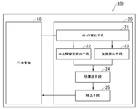
- FIG. 1 is a block diagram of the battery pack 100 according to the first embodiment.
- the battery pack 100 includes a secondary battery 10 and a control device 20. Signal communication is performed between the secondary battery 10 and the control device 20. The signal communication may be wired or wireless.
- the secondary battery 10 is, for example, a lithium secondary battery. The specific configuration of the secondary battery 10 will be described later.
- the secondary battery 10 deteriorates with use.
- the index of deterioration of the secondary battery 10 is SOH.
- SOH is represented by "capacity from full charge to full discharge at the time of deterioration (Ah) / capacity from initial full charge to full discharge (Ah) x 100". Appropriate evaluation of SOH leads to extension of battery life.
- the control device 20 is a control device (controller) that controls the secondary battery 10.
- the control device 20 is, for example, a microcomputer.
- the control device 20 will be described with reference to a specific example of the control device 20.
- the control device 20 includes, for example, a dQ / dV calculation means 21, a two-point capacity calculation means 22, an intensity calculation means 23, a product calculation means 24, and a correction means 25.
- the dQ / dV calculation means 21, the two-point capacity calculation means 22, the strength calculation means 23, the product calculation means 24, and the correction means 25 are, for example, programs stored in the control device 20.
- the dQ / dV calculation means 21 monitors the voltage and the amount of electricity stored in the secondary battery 10.
- the dQ / dV calculation means 21 calculates dQ / dV from the amount of change in voltage and the amount of change in storage amount per unit time.
- the calculation of dQ / dV may be performed at the time of charging or at the time of discharging. It is preferable to calculate dQ / dV at the time of charging.
- the dQ / dV calculation means 21 draws a Q-dQ / dV curve based on the calculated dQ / dV.
- FIG. 2 is an example of a QdQ / dV curve and a QV curve.
- Graph G1 shown in FIG. 2 is a Q-dQ / dV curve.
- the horizontal axis is the amount of electricity stored (capacity) of the secondary battery
- the vertical axis is dQ / dV.
- the graph G2 shown in FIG. 2 is a QV curve.
- the horizontal axis is the storage capacity (capacity) of the secondary battery
- the vertical axis is the voltage of the secondary battery.
- the QdQ / dV curve is a voltage derivative of the QV curve measured by the charge / discharge test.
- the Q-dQ / dV curve has a plurality of extremum points.
- the extremum point has a maximum point and a minimum point.
- P1, P2, P3, and P4 are local maximum points
- B1, B2, and B3 are local minimum points.
- the maximum point in the Q-dQ / dV curve corresponds to a portion where the voltage is flat in the charge / discharge curve (QV curve) in which the horizontal axis is the amount of electricity stored and the vertical axis is the voltage. That is, it corresponds to the portion where the battery reaction of a predetermined stage is occurring.
- the minimum point on the Q-dQ / dV curve corresponds to the portion of the charge / discharge curve (QV curve) where the voltage fluctuates greatly. That is, it corresponds to the point where the battery reaction of a predetermined stage starts or ends.
- the Q-dQ / dV curve data obtained by the dQ / dV calculation means 21 is sent to the two-point capacity calculation means 22 and the strength calculation means 23, respectively.
- the two-point capacity calculation means 22 obtains the capacity ⁇ Q between the two feature points C1 and C2.
- the capacity ⁇ Q is an example of the index ⁇ . Assuming that the coordinates of the feature point C1 are (X1, Y1) and the coordinates of the feature point C2 are (X2, Y2), the capacitance ⁇ Q is
- the selection of the two feature points C1 and C2 is optional.
- the two feature points C1 and C2 are preferably specific points on the Q-dQ / dV curve.
- the Q-dQ / dV curve is drawn, for example, in the charging process of the secondary battery. Therefore, if the feature points C1 and C2 are not specific points in the QdQ / dV curve, it is difficult to mechanically determine that the feature points C1 and C2 have been reached.
- one of a plurality of extremum points is selected as the two feature points C1 and C2, respectively.
- the extremum point may be a maximum point or a minimum point.
- the capacitance between the two feature points C1 and C2 is the inter-peak capacitance, the inter-bottom capacitance, or the inter-peak-bottom capacitance in the QdQ / dV curve.
- the maximum point P2 is designated as the feature point C1
- the minimum point B3 is designated as the feature point C2.
- the maximum point P2 is an extreme value point (maximum point) associated with the voltage stable region that appears second from the fully discharged state in the initial charge / discharge test of the secondary battery.
- the minimum point B3 is an extreme value point (minimum point) associated with a voltage fluctuation region that appears third from the fully discharged state in the initial charge / discharge test of the secondary battery.
- the initial term means a charge / discharge cycle within 10 times.
- the maximum point P2 is, for example, an extreme value point associated with a voltage stable region based on the coexistence state of the stage 2L and the stage 2 in the graphite stage structure of the negative electrode.
- the minimum point B3 is a minimum point associated with the completion of the single-phase reaction of the hexagonal crystals of manganese oxide contained in the positive electrode active material of the secondary battery 10.
- the intensity calculation means 23 selects one of a plurality of extreme points on the Q-dQ / dV curve and obtains the dQ / dV value at the extreme points.
- the dQ / dV value at the selected extremum is an example of the index ⁇ . Assuming that the coordinates of the selected extremum point are (X3, Y3), the index ⁇ is Y3.
- the selection of the extremum point is arbitrary, and any of the maximum points P1, P2, P3, and P4, and any of the minimum points B1, B2, and B3 may be used.
- the intensity calculation means 23 selects the extreme value points regardless of the extreme value points selected as the feature points C1 and C2 in the two-point capacitance calculation means 22.
- the coefficient of determination R 2 increases the relation (1) that indicates the degree of deterioration of the secondary battery 10, the value of SOH estimated the actual value of the SOH The error with is small.
- coefficient of determination R 2 relational expression indicating the degree of deterioration of the secondary battery 10 (1) becomes particularly large.
- the correction frequency can be increased and the error between the actual SOH value and the estimated SOH value can be reduced. This is because the maximum points P2 and P3 and the minimum points B2 and B3 are frequently passed through in the general usage mode of the battery.
- the maximum point P3 is selected, and the dQ / dV value of the maximum point P3 is calculated as the index ⁇ .
- the maximum point P3 is an extreme value point (maximum point) associated with the voltage stable region that appears third from the fully discharged state in the initial charge / discharge test of the secondary battery.
- the maximum point P3 is, for example, the extreme value point associated with the voltage stable region based on the single-phase reaction of the cubic crystal of manganese oxide.
- the capacity ⁇ Q obtained by the two-point capacity calculation means 22 and the dQ / dV value obtained by the strength calculation means 23 are sent to the product calculation means 24, respectively.
- the product calculation means 24 calculates the product X of the capacitance ⁇ Q and the dQ / dV value between the two feature points C1 and C2.
- the product X is, for example, the product of the capacitance ⁇ Q and the dQ / dV value.
- the correction means 25 estimates the SOH of the secondary battery 10 based on the product X sent from the product calculation means 24.
- the correction means corrects the SOH of the secondary battery 10 using the estimated SOH as a correction value.
- the correction value satisfies the following equation (1).
- SOH AX + B ...
- SOH is an estimated degree of deterioration of the secondary battery and is a correction value.
- X is a product calculated by the product calculation means 24.
- a and B are constants.
- the constants A and B are obtained in advance from the relationship between the product X in the calibration sample and the degree of deterioration of the calibration sample.
- the constants A and B differ depending on the combination of the extreme points used to calculate the feature points C1 and C2 and the dQ / dV value.
- the constants A and B are obtained in advance by the calibration sample and are stored in the correction means 25 in advance.
- the calibration sample is prepared with the same material and the same capacity as the actually used secondary battery 10.
- the deterioration behavior of the calibration sample prepared with the same material and the same capacity is similar to the deterioration behavior of the secondary battery 10 actually used.
- a charge / discharge test of the calibration sample is performed to obtain a Q-dQ / dV curve.
- the calibration sample deteriorates as the charge / discharge cycle is repeated, and the shape of the Q-dQ / dV curve changes.
- the calibration sample deteriorates, for example, the position of the vertical axis (dQ / dV) of the extreme value point is lowered, and the position of the horizontal axis (Q) of the extreme value point is shifted.
- the two feature points selected in the calibration sample are the same as the two feature points selected in the secondary battery 10 actually used.
- the secondary battery 10 actually used selects the two feature points selected in the calibration sample as the two feature points.
- two extremum points are selected as two feature points.
- one extreme point is selected from a plurality of extreme points in the Q-dQ / dV curve of the calibration sample, and the dQ / dV value at this extreme point is obtained.
- One extreme point selected in the calibration sample is the same as the extreme point used when determining the dQ / dV value in the actually used secondary battery 10.
- the secondary battery 10 actually used selects the extreme value point selected in the calibration sample as the extreme value point used when obtaining the dQ / dV value.
- the capacitance between the two feature points and the dQ / dV value at a specific extremum point are obtained every predetermined number of charge / discharge cycles. Then, the product of the capacitance between the two feature points and the dQ / dV value at a specific extremum point is calculated each time. In addition, the degree of deterioration (SOH) of the calibration sample at the time when these products are calculated is also obtained.
- the degree of deterioration (SOH) of the calibration sample is obtained by dividing the capacity from full charge to full discharge (Ah) by the capacity from initial full charge to full discharge (Ah) in the number of cycles. Unlike the actual usage mode of the secondary battery 10, the calibration sample does not discharge during charging or charge during discharging, so that SOH can be obtained as an actually measured value.
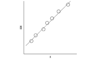
- FIG. 3 shows the relationship between the degree of deterioration of the calibration sample and the product of the capacitance between the two feature points and the dQ / dV value at a specific extremum point. As shown in FIG. 3, there is a linear correlation between the degree of deterioration of the calibration sample and the product of the capacitance between the two feature points and the dQ / dV value at a particular extremum point.
- the correction means 25 sends the obtained correction value to the secondary battery 10.
- the SOH value of the secondary battery 10 is replaced with the correction value.
- the replacement with the correction value is performed, for example, after passing through all the selected minimum points during charging.
- the replacement with the correction value is performed every time the selected extreme value points are passed, for example, during charging.
- the correction may be performed when the correction value is obtained.
- the correction is performed by adding the difference between the holding value (value before correction) and the correction value at the time when the correction value is obtained to the holding value at the time when the correction is performed. You may.
- the correction is gradually performed from the correction value acquisition point to the correction completion point so that the value corresponding to the difference between the possession value and the correction value at the time when the correction value is obtained is added to the possession value at the correction completion point.
- the value may be corrected.
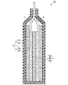
- FIG. 4 is a schematic diagram of the secondary battery according to the first embodiment.
- the secondary battery 10 includes, for example, a power generation element 4, an exterior body 5, and an electrolytic solution (not shown).
- the exterior body 5 covers the periphery of the power generation element 4.
- the exterior body 5 is, for example, a metal laminate film in which a metal foil 5A is coated with a polymer film (resin layer 5B) from both sides.
- the power generation element 4 is connected to the outside by a pair of connected terminals 6.
- the electrolytic solution is housed in the exterior body 5 and impregnated in the power generation element 4.
- the power generation element 4 includes a positive electrode 2, a negative electrode 3, and a separator 1.
- the separator 1 is sandwiched between the positive electrode 2 and the negative electrode 3.
- the separator 1 is, for example, a film having an electrically insulating porous structure. A known separator 1 can be used.
- the positive electrode 2 has a positive electrode current collector 2A and a positive electrode active material layer 2B.
- the positive electrode active material layer 2B is formed on at least one surface of the positive electrode current collector 2A.
- the positive electrode active material layer 2B may be formed on both surfaces of the positive electrode current collector 2A.
- the positive electrode current collector 2A is, for example, a conductive plate material.
- the positive electrode active material layer 2B has, for example, a positive electrode active material, a conductive auxiliary material, and a binder.
- the positive electrode active material reversibly proceeds with the occlusion and release of lithium ions, the desorption and insertion (intercalation) of lithium ions, or the doping and dedoping of lithium ions and counter anions.
- the positive electrode active material is, for example, lithium cobalt oxide (LCO), lithium nickel cobalt manganese composite oxide (NCM), lithium nickel cobalt aluminum composite oxide (NCA), lithium manganese oxide (LMO), lithium iron phosphate (LFP).
- the positive electrode active material layer 2B may contain a plurality of these positive electrode active materials.
- the positive electrode active material may be represented by , for example, LMO 2.
- M is any one of the transition metal elements selected from the group consisting of Co, Ni, Al, Mn, and Fe.
- the positive electrode active material is not limited to these, and known materials can be used. Known conductive auxiliary materials and binders can be used.
- the negative electrode 3 has a negative electrode current collector 3A and a negative electrode active material layer 3B.
- the negative electrode active material layer 3B is formed on at least one surface of the negative electrode current collector 3A.
- the negative electrode active material layer 3B may be formed on both surfaces of the negative electrode current collector 3A.
- the negative electrode current collector 3A is, for example, a conductive plate material.
- the negative electrode active material layer 3B has, for example, a positive electrode active material, a conductive auxiliary material, and a binder.
- the electrolytic solution is sealed in the exterior body 5 and impregnated in the power generation element 4.
- a known electrolytic solution can be used.
- the battery pack 100 according to the first embodiment can correct the SOH of the secondary battery 10 to an appropriate value by the control device 20.
- the graph of c shown in FIG. 5 has higher linearity than the graphs of a and b.
- the graph of c shown in FIG. 5 includes information on the change in the deterioration index value in the horizontal axis (Q) direction of the Q-dQ / dV curve and information on the change in the vertical axis (dQ / dV) direction. It is thought that this is the reason.
- the graph of a shown in FIG. 5 has only information on the change in the index value of deterioration in the horizontal axis (Q) direction of the Q-dQ / dV curve
- the graph of b shown in FIG. 5 has the index value of deterioration. It has only information on changes in the vertical axis (dQ / dV) direction of the Q-dQ / dV curve.
- the same regression line can be drawn between the low temperature deterioration test in which the charge / discharge cycle is performed at 0 ° C. and the high temperature deterioration test in which the charge / discharge cycle is performed at 60 ° C. That is, when the product X of the capacity (index ⁇ ) between the two feature points and the dQ / dV value (index ⁇ ) at the extreme value points is used as the index value of deterioration, the secondary battery 10 is subjected to various temperature conditions. The SOH of the secondary battery 10 can be accurately estimated even when used in.
- the battery pack according to the second embodiment differs from the battery pack according to the first embodiment in the method of selecting feature points in the two-point capacity calculation means 22.
- Other configurations are the same as those of the battery pack according to the first embodiment, and the description of the same configuration is omitted.
- the two-point capacity calculation means 22 obtains the capacity ⁇ Q'between the two feature points C1'and C2'. Assuming that the coordinates of the feature point C1'are (X1', Y1') and the coordinates of the feature point C2 are (X2', Y2'), the capacitance ⁇ Q'is
- the two feature points C1'and C2' are two points sandwiching any one of a plurality of extreme value points.
- the difference between the dQ / dV values of two adjacent extreme value points is divided by a predetermined ratio, and the extreme value point having the smaller dQ / dV value is used as a reference. It is in a position shifted in the vertical axis direction by a predetermined ratio.
- the two feature points C1'and C2' for example, pass through the midpoint in the vertical axis direction of the specific extremum point and the extremum point adjacent to the high capacitance side with respect to the specific extremum point and are parallel to the horizontal axis.
- the straight line and the Q-dQ / dV curve intersect.
- the width of the two feature points C1'and C2' is, for example, the half width of one extreme point.
- the battery pack according to the second embodiment has the same effect as the battery pack 100 according to the first embodiment.
- FIG. 8 is a diagram showing the relationship between the index value of deterioration and the SOH of the secondary battery 10.
- the graph of a shown in FIG. 8 is a diagram in which only the capacitance (index ⁇ ) between the two feature points is used as the index value of deterioration.
- the two feature points are the two points that sandwich the maximum point P2, and the distance between the maximum point P2 and the minimum point B2 is divided into three in the vertical axis direction, and the two points are located at a height of 1/3 from the minimum point B2. Is.
- the horizontal axis of the graph of a is capacitance, and the vertical axis is SOH.
- FIG. 8 is a diagram in which only the dQ / dV value (index ⁇ ) at the extreme value point is used as the index value of deterioration.
- the horizontal axis of the graph of b is the dQ / dV value, and the vertical axis is SOH.
- the graph of c shown in FIG. 8 is a diagram in which the product X of the capacitance ⁇ Q'(index ⁇ ) between the two feature points and the dQ / dV value (index ⁇ ) at the extreme value point is used as the index value of deterioration. be.
- the negative electrode was prepared.
- Graphite was prepared as the negative electrode active material
- SBR styrene-butadiene rubber
- CMC carboxymethyl cellulose
- the condition of one charge / discharge was that the battery was charged to a final voltage of 4.2 V with a constant current corresponding to 0.2 C, and then discharged to 3.0 V with a constant current corresponding to 0.2 C.
- 1C represents a current value for discharging the reference capacity of the battery in 1 hour
- 0.2CC represents a current value of 1/5 of that.
- the measured SOH was obtained by dividing the capacity from full charge to full discharge in each cycle by the capacity from the first full charge to full discharge and multiplying by 100.
- the estimated SOH is a correction value obtained from the above-mentioned relational expression (1). Further, as described above, the estimated SOH may be a correction value obtained by using the inflection point in the QV curve. In this example, the extreme points of dQ / dV were used in order to capture the inflection point more clearly.
- Example 1 the maximum point P2 and the minimum point B3 were selected as the feature points for obtaining the capacity ⁇ Q (index ⁇ ), and the maximum point P2 was used as the maximum point for obtaining the dQ / dV value (index ⁇ ).
- Examples 2 to 5 In Examples 2 to 5, the selection of the two extremum points for obtaining the capacitance ⁇ Q and the extremum points for obtaining the dQ / dV value is different from that in Example 1. Other conditions were the same as in Example 1.
- Example 3 the maximum point P2 and the minimum point B3 were selected as the feature points for obtaining the capacitance ⁇ Q, and the minimum point B3 was used as the extreme value point for obtaining the dQ / dV value.
- Example 5 the maximum point P2 and the maximum point P3 were selected as the feature points for obtaining the capacitance ⁇ Q, and the maximum point P3 was used as the extreme value point for obtaining the dQ / dV value.
- Examples 6 to 8 In Examples 6 to 8, the points using two points sandwiching a specific extreme value point as the feature points for obtaining the capacity ⁇ Q'(index ⁇ ) and the selection of the extreme value points for obtaining the dQ / dV value (index ⁇ ) are selected. However, it is different from Example 1. Other conditions were the same as in Example 1.
- Example 7 two points sandwiching the maximum point P2 were selected as feature points, and the maximum point P4 was used as the extreme point for obtaining the dQ / dV value.
- the feature point is at the height position of the midpoint in the vertical axis direction of the maximum point P2 and the minimum point B2.
- Example 8 two points sandwiching the maximum point P3 were selected as feature points, and the maximum point P4 was used as the extreme point for obtaining the dQ / dV value.
- the feature point is at the height position of the midpoint in the vertical axis direction of the maximum point P3 and the minimum point B3.
- Comparative Example 1 In Comparative Example 1, the estimated SOH was obtained from the integrated current amount without correction.
- Comparative Examples 2-4 In Comparative Examples 2 to 4, the estimated SOH was obtained by using the change in the capacitance ⁇ Q (index ⁇ ) between the two feature points due to deterioration. The two feature points were both extreme points.
- Comparative Examples 5 and 6 In Comparative Examples 5 and 6, the estimated SOH was obtained by using the change in the capacitance ⁇ Q'(index ⁇ ) between the two feature points due to deterioration.
- the two feature points were two points sandwiching a specific extremum point.
- Comparative Example 5 two points sandwiching the maximum point P2 were selected as feature points, and the estimated SOH was obtained using the capacitance ⁇ Q'between these points.
- the feature point is at the height position of the midpoint in the vertical axis direction of the maximum point P2 and the minimum point B2.
- Comparative Example 6 two points sandwiching the maximum point P3 were selected as feature points, and the estimated SOH was obtained using the capacitance ⁇ Q'between these points.
- the feature point is at the height position of the midpoint in the vertical axis direction of the maximum point P3 and the minimum point B3.
- the maximum point P2 was selected as the feature point as the extreme value point for obtaining the dQ / dV value, and the estimated SOH was obtained using the change in the dQ / dV value of the maximum point P2.
- the maximum point P3 was selected as the feature point as the extreme value point for obtaining the dQ / dV value, and the estimated SOH was obtained using the change in the dQ / dV value of the maximum point P3.
- the minimum point B3 was selected as the feature point as the extreme value point for obtaining the dQ / dV value, and the estimated SOH was obtained using the change in the dQ / dV value of the minimum point B3.
- the maximum point P4 was selected as the feature point as the extreme value point for obtaining the dQ / dV value, and the estimated SOH was obtained using the change in the dQ / dV value of the maximum point P4.
- Examples 1 to 8 As shown in Table 1, in Examples 1 to 8 using the product of two parameters, the error between the actually measured SOH and the estimated SOH is larger than that of Comparative Examples 1 to 10 using only one of the parameters. It was small. It is considered that Examples 1 to 8 include information on the change in the vertical axis (dQ / dV) direction of the extreme value point whose position changes due to deterioration and information on the change in the horizontal axis (Q) direction.
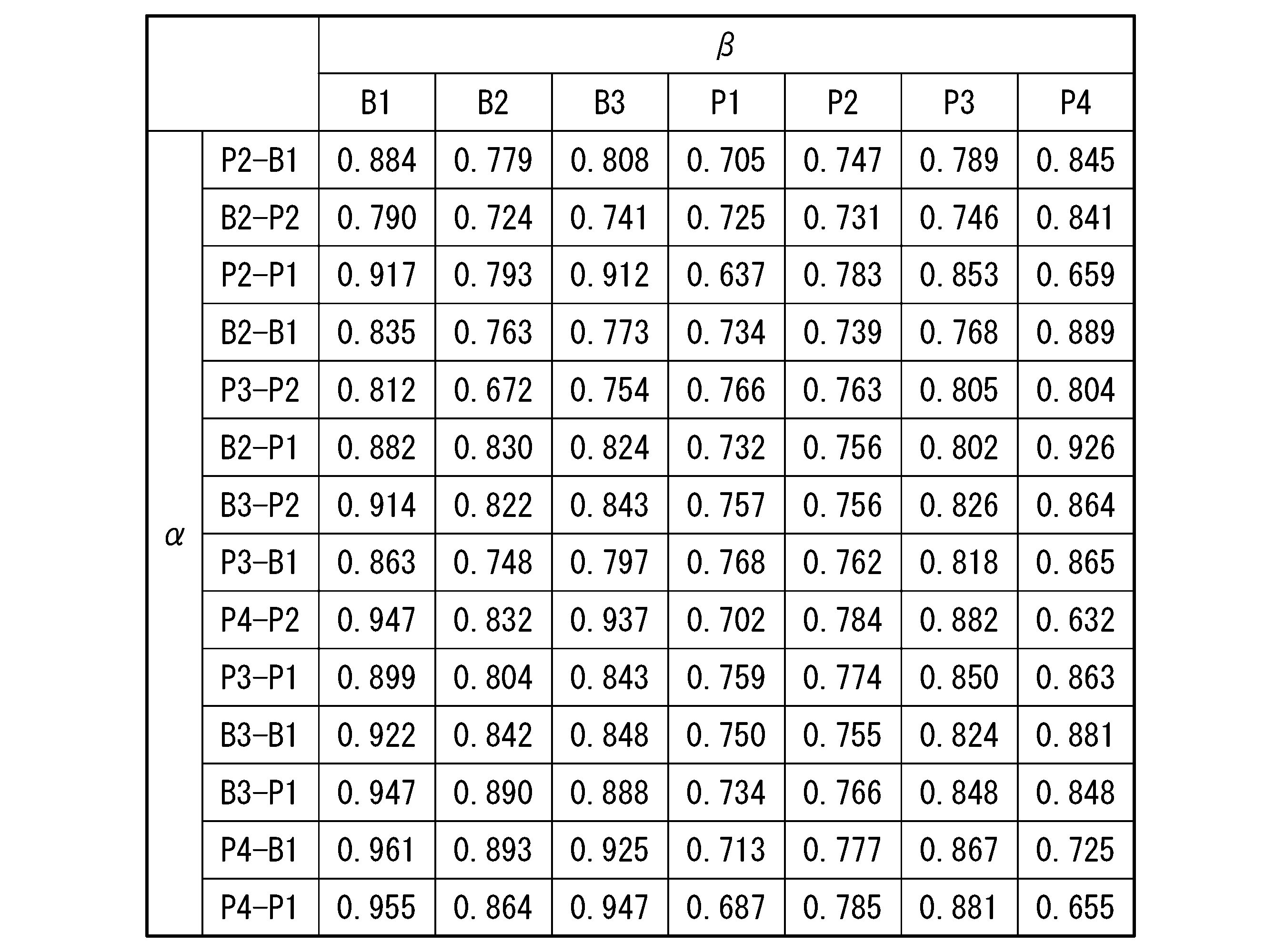
- Example 9 by changing the combination of the extreme point of obtaining the two extreme points and dQ / dV values for determining the capacity Delta] Q, determine the coefficient of determination R 2 of the regression line relationship (1) in each case rice field.
- Example 9 the same secondary battery as in Example 1 was used. Determination coefficient of the regression line as R 2 is large, has a high linear correlation. Accordingly, the coefficient of determination as R 2 is large, it can be said that an error of the SOH of the measured and SOH estimation is reduced.
- Table 2 The results of Example 9 are summarized in Table 2.
- the Q-dQ / dV curve and the SOH value in each of the three deteriorated states of the lithium ion secondary battery (hereinafter referred to as the first deteriorated state, the second deteriorated state, and the third deteriorated state) are obtained.
- the Q-dQ / dV curve in the first deteriorated state, the Q-dQ / dV curve in the second deteriorated state, and the Q-dQ / dV curve in the third deteriorated state are output, and two features are obtained.
- the product of the capacitance between the points and the dQ / dV value at the extremum was calculated.
- a good linear relationship represented by the equation Y AX + B was obtained.
- Y AX + B
Landscapes
- Chemical & Material Sciences (AREA)
- Chemical Kinetics & Catalysis (AREA)
- Electrochemistry (AREA)
- General Chemical & Material Sciences (AREA)
- General Physics & Mathematics (AREA)
- Physics & Mathematics (AREA)
- Engineering & Computer Science (AREA)
- Manufacturing & Machinery (AREA)
- Composite Materials (AREA)
- Inorganic Chemistry (AREA)
- Materials Engineering (AREA)
- Microelectronics & Electronic Packaging (AREA)
- Secondary Cells (AREA)
- Tests Of Electric Status Of Batteries (AREA)
- Charge And Discharge Circuits For Batteries Or The Like (AREA)
Abstract
この二次電池の制御装置は、Q-dQ/dV曲線における二つの特徴点又はこれと数学的に等価な二つの点の間の容量をαとし、前記Q-dQ/dV曲線に表れる複数の極値点のうちのいずれかの極値点又はこれと数学的に等価な点におけるdQ/dV値をβとし、前記αと前記βとの積をXとし、校正サンプルにおける前記Xと前記校正サンプルの劣化度合いとの関係から予め求められる定数をA、Bとした際に、前記二次電池の劣化度合いSOHを、SOH=AX+B ・・・(1)に補正する。この二次電池の制御装置を備える電池パックは、安全性が高く、エネルギーの安定供給に寄与し、持続可能な開発目標に貢献する。
Description
本発明は、二次電池の制御装置、電池パックおよび二次電池の制御方法に関する。
二次電池の状態の指標としてSOC(State of Charge)やSOH(State of Health)が知られている。SOCは、二次電池の残容量を示す指標であり、SOHは電池の劣化状態を示す指標である。SOCは、満充電容量に対する残容量の割合である。SOHは、初期の満充電から満放電までの容量に対する劣化時の満充電から満放電までの容量の割合である。
例えば、特許文献1には、二次電池の充電時に、電圧の変化量に対する蓄電量の変化量の割合であるdQ/dVと二次電池の電圧Vから得られるV-dQ/dV曲線の極大点の電圧値から容量低下率(SOHに対応する)を推定する方法が記載されている。
例えば、特許文献2には、二次電池の放電時に、dQ/dVを求め、電圧に対するdQ/dVの変化量の最大値からSOHを求める方法が記載されている。
二次電池が充放電サイクルを繰り返すと、実際のSOHの値から推定されるSOHの値がずれる場合がある。特許文献1及び2に記載の方法では、実際のSOHの値と推定されるSOHの値との誤差を十分小さくすることができない。
本開示は上記問題に鑑みてなされたものであり、二次電池の劣化状態を適正値に補正できる、二次電池の制御装置、電池パックおよび二次電池の制御方法を提供することを目的とする。
上記課題を解決するため、以下の手段を提供する。
(1)第1の態様にかかる二次電池の制御装置は、二次電池の電圧の変化量に対する蓄電量の変化量の割合であるdQ/dVを縦軸とし、前記二次電池の蓄電量を横軸としたQ-dQ/dV曲線における二つの特徴点又はこれと数学的に等価な二つの点の間の容量をαとし、前記Q-dQ/dV曲線に表れる複数の極値点のうちのいずれかの極値点又はこれと数学的に等価な点におけるdQ/dV値をβとし、前記αと前記βとの積をXとし、校正サンプルにおける前記Xと前記校正サンプルの劣化度合いとの関係から予め求められる定数をA、Bとした際に、前記二次電池の劣化度合いSOHを、SOH=AX+B ・・・(1)に補正する。
(2)上記態様にかかる二次電池の制御方法において、前記二つの特徴点は、いずれも前記複数の極値点のうちのいずれかであってもよい。
(3)上記態様にかかる二次電池の制御方法において、前記二つの特徴点は、前記複数の極値点のうちのいずれかの極値点を挟む二点であってもよい。
(4)上記態様にかかる二次電池の制御方法において、前記二つの特徴点に挟まれる極値点は、二次電池の電圧の変化量に対する蓄電量の変化量の割合であるdQ/dVを縦軸とし、前記二次電池の電圧を横軸としたV-dQ/dV曲線において、3.6V以上3.8V以下の電圧範囲に表れる極大点であってもよい。
(5)上記態様にかかる二次電池の制御方法は、前記dQ/dVを算出するdQ/dV算出手段と、前記Q-dQ/dV曲線における前記二つの特徴点を選択し、前記二つの特徴点の間の容量を求める二点間容量算出手段と、前記Q-dQ/dV曲線における前記複数の極値点のうちのいずれかの極値点を選択し、前記極値点におけるdQ/dV値を求める強度算出手段と、前記二つの特徴点の間の容量と前記dQ/dV値との積を求める積算手段と、前記積算手段で求められた値に基づいて、前記二次電池の劣化度合いを補正値に補正する補正手段と、を有してもよい。
(6)第2の態様にかかる電池パックは、二次電池と上記態様にかかる二次電池の制御装置とを備える。
(7)上記態様にかかる電池パックにおいて、前記二次電池は、正極に活物質として、リチウムニッケルコバルトマンガン複合酸化物(NCM)及びリチウムマンガン酸化物(LMO)を含んでもよい。
(8)第3の態様にかかる二次電池の制御方法は、二次電池の電圧の変化量に対する蓄電量の変化量の割合であるdQ/dVを縦軸とし、前記二次電池の蓄電量を横軸としたQ-dQ/dV曲線における二つの特徴点又はこれと数学的に等価な二つの点の間の容量をαとし、前記Q-dQ/dV曲線に表れる複数の極値点のうちのいずれかの極値点又はこれと数学的に等価な点におけるdQ/dV値をβとし、前記αと前記βとの積をXとし、校正サンプルにおける前記Xと前記校正サンプルの劣化度合いとの関係から予め求められる定数をA、Bとした際に、前記二次電池の劣化度合いSOHを、SOH=AX+B ・・・(1)に補正する。
上記態様に係る二次電池の制御装置、電池パックおよび二次電池の制御方法は、二次電池の劣化状態を適正値に補正できる。
また上記態様に係る二次電池の制御装置、電池パックおよび二次電池の制御方法は、二次電池の安全性を高め、エネルギーの安定供給に寄与し、持続可能な開発目標に貢献する。
また上記態様に係る二次電池の制御装置、電池パックおよび二次電池の制御方法は、二次電池の安全性を高め、エネルギーの安定供給に寄与し、持続可能な開発目標に貢献する。
以下、実施形態について、図を適宜参照しながら詳細に説明する。以下の説明で用いる図面は、特徴をわかりやすくするために便宜上特徴となる部分を拡大して示している場合があり、各構成要素の寸法比率等は実際とは異なっていることがある。以下の説明において例示される材料、寸法等は一例であって、本発明はそれらに限定されるものではなく、その要旨を変更しない範囲で適宜変更して実施することが可能である。
「第1実施形態」
図1は、第1実施形態にかかる電池パック100のブロック図である。電池パック100は、二次電池10と制御装置20とを備える。二次電池10と制御装置20との間では信号の通信が行われる。信号の通信は、有線でも無線でもよい。
図1は、第1実施形態にかかる電池パック100のブロック図である。電池パック100は、二次電池10と制御装置20とを備える。二次電池10と制御装置20との間では信号の通信が行われる。信号の通信は、有線でも無線でもよい。
二次電池10は、例えば、リチウム二次電池である。二次電池10の具体的な構成は後述する。二次電池10は、使用に伴い劣化する。二次電池10の劣化の指標がSOHである。SOHは、「劣化時の満充電から満放電までの容量(Ah)/初期の満充電から満放電までの容量(Ah)×100」で表される。SOHを適切に評価することは、電池の寿命延長に繋がる。
制御装置20は、二次電池10を制御する制御装置(コントローラー)である。制御装置20は、例えば、マイコンである。
制御装置20は、例えば、二次電池10の劣化度合いをSOH=AX+B ・・・(1)に補正する制御プログラムを有する。以下、制御装置20の具体的な例を用いて、制御装置20について説明する。
制御装置20は、例えば、dQ/dV算出手段21と二点間容量算出手段22と強度算出手段23と積算出手段24と補正手段25とを有する。dQ/dV算出手段21、二点間容量算出手段22、強度算出手段23、積算出手段24及び補正手段25は、例えば、制御装置20に格納されたプログラムである。
dQ/dV算出手段21は、二次電池10の電圧及び蓄電量をモニターする。dQ/dV算出手段21は、単位時間当たりの電圧の変化量と蓄電量の変化量からdQ/dVを算出する。dQ/dVの算出は充電時に行っても、放電時に行ってもよい。dQ/dVの算出は充電時に行うことが好ましい。
dQ/dV算出手段21は、算出されたdQ/dVを基に、Q-dQ/dV曲線を描く。図2は、Q-dQ/dV曲線及びQ-V曲線の一例である。図2に示すグラフG1は、Q-dQ/dV曲線である。Q-dQ/dV曲線は、横軸が二次電池の蓄電量(容量)であり、縦軸がdQ/dVである。図2に示すグラフG2は、Q-V曲線である。Q-V曲線は、横軸が二次電池の蓄電量(容量)であり、縦軸が二次電池の電圧である。Q-dQ/dV曲線は、充放電試験によって測定したQ-V曲線を電圧で微分したものである。
図2に示すように、Q-dQ/dV曲線は、複数の極値点を有する。極値点は、極大点と極小点とがある。図2において、P1、P2、P3、P4が極大点であり、B1、B2、B3が極小点である。Q-dQ/dV曲線における極大点は、横軸を蓄電量とし縦軸を電圧とした充放電曲線(Q-V曲線)において電圧が平坦な部分に対応する。すなわち、所定のステージの電池反応が生じている部分に対応する。Q-dQ/dV曲線における極小点は、充放電曲線(Q-V曲線)において電圧の変動が大きい部分に対応する。すなわち、所定のステージの電池反応が開始した点又は終了した点に対応する。
dQ/dV算出手段21で求められたQ-dQ/dV曲線のデータは、二点間容量算出手段22と強度算出手段23とのそれぞれに送られる。
二点間容量算出手段22は、二つの特徴点C1,C2間の容量ΔQを求める。容量ΔQは、指標αの一例である。特徴点C1の座標を(X1、Y1)、特徴点C2の座標を(X2、Y2)とすると、容量ΔQは|X2-X1|である。
二つの特徴点C1、C2の選択は任意である。二つの特徴点C1、C2は、Q-dQ/dV曲線における特異的な点であることが好ましい。Q-dQ/dV曲線は、例えば、二次電池の充電過程に描かれる。そのため、特徴点C1、C2がQ-dQ/dV曲線における特異的な点でないと、特徴点C1、C2に至ったと機械的に判断することが難しくなるためである。
例えば、二つの特徴点C1、C2として、複数の極値点のうちのいずれかをそれぞれ選択する。極値点は、極大点でも極小点でもよい。二つの特徴点C1,C2間の容量は、Q-dQ/dV曲線におけるピーク間容量、ボトム間容量、またはピーク・ボトム間容量となる。
例えば、図2では、極大点P2を特徴点C1とし、極小点B3を特徴点C2としている。極大点P2は、二次電池の初期の充放電試験において、満放電状態から2番目に表れる電圧安定領域に伴う極値点(極大点)である。極小点B3は、二次電池の初期の充放電試験において、満放電状態から3番目に表れる電圧変動領域に伴う極値点(極小点)である。ここで初期とは、10回以内の充放電サイクルを示す。極大点P2は、例えば、負極のグラファイトのステージ構造において、ステージ2Lとステージ2との共存状態に基づく電圧安定領域に伴う極値点である。極小点B3は、二次電池10の正極活物質に含まれるマンガン酸化物の六方晶の単相反応が完了することに伴う極小点である。
強度算出手段23は、Q-dQ/dV曲線における複数の極値点のうちのいずれかの極値点を選択し、極値点におけるdQ/dV値を求める。選択された極値点におけるdQ/dV値は、指標βの一例である。選択された極値点の座標を(X3,Y3)とすると、指標βはY3である。
極値点の選択は任意であり、極大点P1、P2、P3、P4のいずれでも、極小点B1、B2、B3のいずれでもよい。強度算出手段23は、極値点を二点間容量算出手段22において特徴点C1,C2として選択した極値点と無関係に選択する。極値点として極小点B1、B2、B3を用いると、二次電池10の劣化度合いを示す関係式(1)の決定係数R2が大きくなり、実際のSOHの値と推定されるSOHの値との誤差が小さくなる。極値点として極小点B1を用いると、二次電池10の劣化度合いを示す関係式(1)の決定係数R2が特に大きくなる。また極値点として、極大点P2、P3又は極小点B2、B3を用いると、補正頻度を増やすことができ、実際のSOHの値と推定されるSOHの値との誤差が小さくできる。極大点P2、P3及び極小点B2、B3は、電池の一般的な使用態様において通過頻度が多いためである。
例えば、図2では、極大点P3を選択し、極大点P3のdQ/dV値を指標βとして算出する。極大点P3は、二次電池の初期の充放電試験において、満放電状態から3番目に表れる電圧安定領域に伴う極値点(極大点)である。極大点P3は、例えば、マンガン酸化物の立方晶の単相反応に基づく電圧安定領域に伴う極値点である。
二点間容量算出手段22で求められた容量ΔQと強度算出手段23で求められたdQ/dV値とは、それぞれ積算出手段24へ送られる。積算出手段24は、二つの特徴点C1、C2の間の容量ΔQとdQ/dV値との積Xを算出する。積Xは、例えば、容量ΔQとdQ/dV値とを掛け合わせたものである。
補正手段25は、積算出手段24から送られた積Xに基づいて、二次電池10のSOHを推定する。補正手段は、推定されたSOHを補正値として、二次電池10のSOHを補正する。
補正値は、以下の式(1)を満たす。
SOH=AX+B ・・・(1)
式(1)において、SOHは二次電池の推定される劣化度合いであり、補正値である。式(1)において、Xは積算出手段24で算出された積である。式(1)において、A、Bは、定数である。
SOH=AX+B ・・・(1)
式(1)において、SOHは二次電池の推定される劣化度合いであり、補正値である。式(1)において、Xは積算出手段24で算出された積である。式(1)において、A、Bは、定数である。
A、Bの定数は校正サンプルにおける積Xと校正サンプルの劣化度合いとの関係から予め求められる。A、Bの定数は、特徴点C1,C2となる極値点及びdQ/dV値の算出に用いられた極値点の組み合わせによって異なる。A、Bの定数は、校正サンプルによって事前に求められ、補正手段25に予め記憶されている。
ここで、A、Bの定数の求め方について説明する。まず校正サンプルを準備する。校正サンプルは、実際に使用される二次電池10と同じ材料、同じ容量で作製する。同じ材料及び同じ容量で作製された校正サンプルの劣化挙動は、実際に使用される二次電池10の劣化挙動と近似する。
次いで、校正サンプルの充放電試験を行い、Q-dQ/dV曲線を得る。校正サンプルは、充放電サイクルを繰り返すと劣化し、Q-dQ/dV曲線の形が変化する。校正サンプルが劣化すると、例えば、極値点の縦軸(dQ/dV)の位置が下がり、極値点の横軸(Q)の位置がシフトする。校正サンプルの劣化に伴うQ-dQ/dV曲線の極値点の縦軸(dQ/dV)方向及び横軸(V)方向へのシフトの挙動は、二次電池10の劣化に伴う極値点のシフトの挙動と略一致する。
次いで、校正サンプルのQ-dQ/dV曲線における二つの特徴点を選択し、これらの特徴点間の容量を求める。校正サンプルにおいて選択される二つの特徴点は、実際に使用される二次電池10において選択される二つの特徴点と同じある。換言すると、実際に使用される二次電池10は、二つの特徴点として、校正サンプルにおいて選択された二つの特徴点を選択する。例えば、二つの特徴点として、二つの極値点を選択する。
また校正サンプルのQ-dQ/dV曲線における複数の極値点から一つの極値点を選択し、この極値点におけるdQ/dV値を求める。校正サンプルにおいて選択される一つの極値点は、実際に使用される二次電池10においてdQ/dV値を求める際に用いられる極値点と同じある。換言すると、実際に使用される二次電池10は、dQ/dV値を求める際に用いる極値点として、校正サンプルにおいて選択された極値点を選択する。
校正サンプルにおいて、二つの特徴点の間の容量と特定の極値点におけるdQ/dV値は、充放電サイクルを所定回数行うごとに求める。そして二つの特徴点の間の容量と特定の極値点におけるdQ/dV値とを求めるたびにこれらの積を算出する。またこれらの積を算出した時点における校正サンプルの劣化度合い(SOH)も求める。校正サンプルの劣化度合い(SOH)は、当該サイクル回数において満充電から満放電までの容量(Ah)を初期の満充電から満放電までの容量(Ah)で割ることで求められる。校正サンプルは、実際の二次電池10の使用態様と異なり、充電途中に放電を行ったり、放電途中に充電を行うことがないため、実測値としてSOHを求めることができる。
図3は、校正サンプルの劣化度合いと、二つの特徴点の間の容量と特定の極値点におけるdQ/dV値との積と、の関係を示す。図3に示すように、校正サンプルの劣化度合いと、二つの特徴点の間の容量と特定の極値点におけるdQ/dV値との積と、の間には、線形相関がある。
次いで、図3に示す校正サンプルのプロットに回帰直線を引く。回帰直線の傾きが定数Aであり、回帰直線の切片が定数Bである。回帰直線の決定係数R2が大きいほど、回帰直線の線形相関が強く、SOHの推定精度が高まる。
補正手段25は、求められた補正値を二次電池10に送る。二次電池10のSOHの値は補正値に置き換えられる。補正値への置き換えは、例えば、充電時において、選択した極小点をすべて通過した後に行う。補正値への置き換えは、例えば、充電時において、選択した極値点をすべて通過する毎に行う。当該補正は、補正値が得られた時点で行ってもよい。また当該補正は、補正値が得られた後に、補正値が得られた時点における保有値(補正前の値)と補正値との差分を、補正が行われる時点における保有値に加えることで行ってもよい。また当該補正は、補正値が得られた時点における保有値と補正値との差分にあたる値が、補正完了点における保有値に対して加えられるように、補正値取得点から補正完了点まで徐々に値を補正していってもよい。
SOHを補正値に置き換えると、例えば、連続的に変化するSOHの値が不連続に変化する。読みだされるSOHの値が不連続に変化したということは、補正が行われたと推定できる。また補正された時点における補正値が、上記関係式(1)を満たす場合、第1実施形態にかかる二次電池の制御方法が行われたと推定できる。
図4は、第1実施形態にかかる二次電池の模式図である。二次電池10は、例えば、発電素子4と外装体5と電解液(図示略)とを備える。外装体5は、発電素子4の周囲を被覆する。外装体5は、例えば、金属箔5Aを高分子膜(樹脂層5B)で両側からコーティングした金属ラミネートフィルムである。発電素子4は、接続された一対の端子6によって外部と接続される。電解液は、外装体5内に収容され、発電素子4内に含浸している。
発電素子4は、正極2と負極3とセパレータ1とを備える。セパレータ1は、正極2と負極3とに挟まれる。セパレータ1は、例えば、電気絶縁性の多孔質構造を有するフィルムである。セパレータ1は、公知のものを用いることができる。
正極2は、正極集電体2Aと正極活物質層2Bとを有する。正極活物質層2Bは、正極集電体2Aの少なくとも一面に形成されている。正極活物質層2Bは、正極集電体2Aの両面に形成されていてもよい。正極集電体2Aは、例えば、導電性の板材である。正極活物質層2Bは、例えば、正極活物質と導電助材とバインダーとを有する。
正極活物質は、リチウムイオンの吸蔵及び放出、リチウムイオンの脱離及び挿入(インターカレーション)、又は、リチウムイオンとカウンターアニオンのドープ及び脱ドープを可逆的に進行させる。正極活物質は、例えば、コバルト酸リチウム(LCO)、リチウムニッケルコバルトマンガン複合酸化物(NCM)、リチウムニッケルコバルトアルミニウム複合酸化物(NCA)、リチウムマンガン酸化物(LMO)、リン酸鉄リチウム(LFP)である。正極活物質層2Bは、これらの正極活物質を複数含んでもよい。正極活物質は、例えば、LMO2で表されるものでもよい。Mは、Co、Ni、Al、Mn、Feからなる群から選択されるいずれか一つの遷移金属元素である。正極活物質は、これらに限られず公知のものを用いることができる。導電助材及びバインダーは公知のものを用いることができる。
負極3は、負極集電体3Aと負極活物質層3Bとを有する。負極活物質層3Bは、負極集電体3Aの少なくとも一面に形成されている。負極活物質層3Bは、負極集電体3Aの両面に形成されていてもよい。負極集電体3Aは、例えば、導電性の板材である。負極活物質層3Bは、例えば、正極活物質と導電助材とバインダーとを有する。
負極活物質は、イオンを吸蔵・放出可能な化合物であればよく、公知のリチウムイオン二次電池に用いられる負極活物質を使用できる。負極活物質は、例えば、グラファイトである。負極活物質は、金属リチウム、シリコン化合物等でもよい。
電解液は、外装体5内に封入され、発電素子4に含浸している。電解液は、公知のものを用いることができる。
第1実施形態にかかる電池パック100は、制御装置20によって二次電池10のSOHを適切な値に補正できる。
第1実施形態にかかる制御装置20は、Q-dQ/dV曲線における二つの特徴点の間の容量と極値点におけるdQ/dV値との積を利用して、二次電池10のSOHを補正する。二つの特徴点の間の容量は、劣化に伴うQ-dQ/dV曲線の横軸(Q)方向の変化の情報を含む。極値点におけるdQ/dV値は、劣化に伴うQ-dQ/dV曲線の縦軸(dQ/dV)方向の変化の情報を含む。劣化に伴うQ-dQ/dV曲線の形の変化を、異なる2方向の形状変化の情報を有する値を利用して特定することで、二次電池10の劣化状態を正確に把握することができる。
図5は、劣化の指標値と二次電池10のSOHとの関係を示した図である。図5に示すaのグラフは、二つの特徴点の間の容量(指標α)のみを劣化の指標値として用いた図である。aのグラフの横軸は容量であり、縦軸はSOHである。aのグラフにおける二つの特徴点は二つの極値点であり、極大点P4と極小点B1である。図5に示すbのグラフは、極値点におけるdQ/dV値(指標β)のみを劣化の指標値として用いた図である。bのグラフの横軸はdQ/dV値であり、縦軸はSOHである。bのグラフにおける極値点は、極小点B1である。図5に示すcのグラフは、二つの特徴点の間の容量(指標α)と極値点におけるdQ/dV値(指標β)との積Xを劣化の指標値として用いた図である。cのグラフの横軸は、二つの特徴点の間の容量とdQ/dV値との積であり、縦軸はSOHである。
図5に示すcのグラフは、a及びbのグラフより線形性が高い。図5に示すcのグラフは、劣化の指標値がQ-dQ/dV曲線の横軸(Q)方向の変化の情報、及び、縦軸(dQ/dV)方向の変化の情報を含んでいるためと考えられる。図5に示すaのグラフは、劣化の指標値がQ-dQ/dV曲線の横軸(Q)方向の変化の情報のみを有し、図5に示すbのグラフは、劣化の指標値がQ-dQ/dV曲線の縦軸(dQ/dV)方向の変化の情報のみを有している。
また図5に示すcのグラフは、充放電サイクルを0℃で行った低温劣化試験と、充放電サイクルを60℃で行った高温劣化試験とで、同じ回帰直線が引ける。すなわち、劣化の指標値として、二つの特徴点の間の容量(指標α)と極値点におけるdQ/dV値(指標β)との積Xを利用すると、二次電池10を様々な温度条件での使用した場合にも、二次電池10のSOHを正確に推定することができる。
以上、本発明の実施形態について図面を参照して詳述したが、各実施形態における各構成及びそれらの組み合わせ等は一例であり、本発明の趣旨から逸脱しない範囲内で、構成の付加、省略、置換、及びその他の変更が可能である。
例えば、二つの特徴点の間の容量に変えて、二つの特徴点と数学的に等価な二つの点の容量を積の算出に用いてもよく、極値点におけるdQ/dV値に変えて、極値点と数学的に等価な点におけるdQ/dV値を積の算出に用いてもよい。ここで「数学的に等価な点」とは、数学的な変換により等価な関係にある点をいう。例えば、Q-dQ/dV曲線は、Q-V曲線を電圧Vで微分したものである。したがって、dQ/dVの極値点のそれぞれは、通常のQ-V曲線における変曲点と数学的に等価である。またQ-dQ/dV曲線は、数学的な変換によりV-dQ/dV曲線に書き換えることもできる。
例えば、Q-V曲線において傾きの逆数が、最大または最小となる2つの変曲点を選択し、この2つの変曲点の間の容量を用いて、補正値を算出してもよい。また例えば、Q-V曲線における変曲点の傾きを用いて、補正値を算出してもよい。この場合、校正サンプルにおいて定数A,Bを導出する場合においても、Q-V曲線の変曲点を用いる。この場合、補正の算出に用いる指標が変わるだけであり、二つの特徴点の間の容量とdQ/dV値の積を用いる場合と同様の手順で推定される補正値(SOH)を算出できる。
「第2実施形態」
第2実施形態にかかる電池パックは、二点間容量算出手段22における特徴点の選択の仕方が、第1実施形態にかかる電池パックと異なる。その他の構成は、第1実施形態にかかる電池パックと同じであり、同様の構成についての説明は省く。
第2実施形態にかかる電池パックは、二点間容量算出手段22における特徴点の選択の仕方が、第1実施形態にかかる電池パックと異なる。その他の構成は、第1実施形態にかかる電池パックと同じであり、同様の構成についての説明は省く。
二点間容量算出手段22は、二つの特徴点C1’,C2’間の容量ΔQ’を求める。特徴点C1’の座標を(X1’、Y1’)、特徴点C2の座標を(X2’、Y2’)とすると、容量ΔQ’は|X2’-X1’|である。ΔQ’は、指標αの一例である。
二つの特徴点C1’、C2’は、複数の極値点のうちのいずれかの極値点を挟む二点である。二つの特徴点C1’、C2’は、例えば、隣接する2つの極値点のdQ/dV値の差を所定の比率で分割し、dQ/dV値が小さい方の極値点を基準に、所定の比率分だけ縦軸方向にシフトした位置にある。二つの特徴点C1’、C2’は、例えば、特定の極値点と特定の極値点に対して高容量側に隣接する極値点との縦軸方向の中点を通り横軸と平行な直線とQ-dQ/dV曲線とが交差する位置にある。二つの特徴点C1’、C2’の幅は、例えば、一つの極値点の半値幅である。
二つの特徴点C1’、C2’に挟まれる極値点は、二次電池の電圧の変化量に対する蓄電量の変化量の割合であるdQ/dVを縦軸とし、前記二次電池の電圧を横軸としたV-dQ/dV曲線において、3.6V以上3.8V以下の電圧範囲に表れる極大点である。図7は、Q-dQ/dV曲線をV-dQ/dV曲線に変換した図である。極大点P2は、3.6V以上3.8V以下の電圧範囲に表れる極大点である。極大点P2は、劣化に伴う変化が大きく、当該点を劣化の指標に用いると、二次電池10のSOHを正確に推定することができる。
第2実施形態にかかる電池パックは、第1実施形態にかかる電池パック100と同様の効果が得られる。
図8は、劣化の指標値と二次電池10のSOHとの関係を示した図である。図8に示すaのグラフは、二つの特徴点の間の容量(指標α)のみを劣化の指標値として用いた図である。二つの特徴点は、極大点P2を挟む2点であり、極大点P2と極小点B2との間を縦軸方向に3分割し、極小点B2から1/3の高さ位置にある2点である。aのグラフの横軸は容量であり、縦軸はSOHである。図8に示すbのグラフは、極値点におけるdQ/dV値(指標β)のみを劣化の指標値として用いた図である。bのグラフの横軸はdQ/dV値であり、縦軸はSOHである。図8に示すcのグラフは、二つの特徴点の間の容量ΔQ’(指標α)と極値点におけるdQ/dV値(指標β)との積Xを劣化の指標値として用いた図である。
aのグラフは回帰直線の決定係数R2が0.784であり、bのグラフは回帰直線の決定係数R2が0.004であるのに対し、cのグラフは回帰直線の決定係数R2が0.934である。すなわち、cのグラフは、a及びbのグラフより線形性が高い。第1実施形態において示したのと同様に、cのグラフは、劣化の指標値がQ-dQ/dV曲線の横軸(Q)方向の変化の情報、及び、縦軸(dQ/dV)方向の変化の情報を含んでいるためと考えられる。
またcのグラフは、充放電サイクルを0℃で行った低温劣化試験と、充放電サイクルを60℃で行った高温劣化試験とで、同じ回帰直線が引ける。すなわち、劣化の指標値として、極値点を挟む2点間の容量ΔQ’と極値点におけるdQ/dV値との積Xを利用した場合においても、様々な温度領域で、二次電池10のSOHを正確に推定することができる。
「実施例1」
実施例1の二次電池としてリチウムイオン二次電池を作製した。まず、正極を準備した。正極活物質としてLiNi0.33Mn0.33Co0.33O2(NCM)とLiMn2O4(LMO)を混合したもの、導電材としてカーボンブラック、バインダーとしてポリフッ化ビニリデン(PVDF)を準備した。NCMとLMOとの重量比は、8:2とした。これらを溶媒中で混合し、塗料を作製し、アルミ箔からなる正極集電体上に塗布した。正極活物質と導電材とバインダーの質量比は、95:2:3とした。塗布後に、溶媒は除去した。正極活物質の目付量が10.0mg/cm2の正極シートを作製した。
実施例1の二次電池としてリチウムイオン二次電池を作製した。まず、正極を準備した。正極活物質としてLiNi0.33Mn0.33Co0.33O2(NCM)とLiMn2O4(LMO)を混合したもの、導電材としてカーボンブラック、バインダーとしてポリフッ化ビニリデン(PVDF)を準備した。NCMとLMOとの重量比は、8:2とした。これらを溶媒中で混合し、塗料を作製し、アルミ箔からなる正極集電体上に塗布した。正極活物質と導電材とバインダーの質量比は、95:2:3とした。塗布後に、溶媒は除去した。正極活物質の目付量が10.0mg/cm2の正極シートを作製した。
次いで負極を準備した。負極活物質としてグラファイト、バインダーとしてスチレン・ブタジエンゴム(SBR)、増粘剤としてカルボキシメチルセルロース(CMC)を準備した。これらを蒸留水に分散させ、塗料を作製し、銅箔からなる負極集電体上に塗布した。負極活物質とバインダーおよび増粘剤は質量比で95:3:2とした。塗布後に乾燥させ、負極活物質の目付量が10.0mg/cm2の負極シートを作製した。
上記で作製した正極および負極と、セパレータを介して積層した。セパレータには、ポリエチレンとポリプロピレンの積層体を用いた。得られた発電部を調製した電解液に含浸させてから外装体内に封入した後、真空シールし、評価用のリチウム二次電池を作製した。電解液は、エチレンカーボネート(EC)とジメチルカーボネート(DEC)が等量混合された溶媒に、六フッ化リン酸リチウム(LiPF6)1.5mol/Lを溶解させたものとした。
リチウム二次電池の充放電サイクルを繰り返しながら、1000サイクル目における実測のSOHと推定のSOHとの差を求めた。充放電サイクルは、0℃の低温環境で行った。
1回の充放電の条件は、0.2Cに相当する定電流で、終止電圧4.2Vまで充電し、その後0.2Cに相当する定電流で3.0Vまで放電した。1Cは、電池の基準容量を1時間で放電する電流値を表し、0.2CCとはその1/5の電流値を表す。実測のSOHは、各サイクルの満充電から満放電までの容量を初回の満充電から満放電までの容量で割り、100をかけることで求めた。推測のSOHは、上述の関係式(1)から求められた補正値である。また上述のように、推測のSOHは、Q-V曲線における変曲点を用いて、求められた補正値であってもよい。本実施例は、変曲点をより鮮明に捉えるためにdQ/dVの極値点を用いた。
実施例1は、容量ΔQ(指標α)を求める特徴点として極大点P2と極小点B3とを選択し、dQ/dV値(指標β)を求める極値点として極大点P2を用いた。
「実施例2~5」
実施例2~5は、容量ΔQを求める2つの極値点及びdQ/dV値を求める極値点の選択が、実施例1と異なる。その他の条件は、実施例1と同様とした。
実施例2~5は、容量ΔQを求める2つの極値点及びdQ/dV値を求める極値点の選択が、実施例1と異なる。その他の条件は、実施例1と同様とした。
実施例2は、容量ΔQを求める特徴点として極大点P2と極小点B3とを選択し、dQ/dV値を求める極値点として極大点P3を用いた。
実施例3は、容量ΔQを求める特徴点として極大点P2と極小点B3とを選択し、dQ/dV値を求める極値点として極小点B3を用いた。
実施例4は、容量ΔQを求める特徴点として極大点P2と極小点B2とを選択し、dQ/dV値を求める極値点として極大点P3を用いた。
実施例5は、容量ΔQを求める特徴点として極大点P2と極大点P3とを選択し、dQ/dV値を求める極値点として極大点P3を用いた。
「実施例6~8」
実施例6~8は、容量ΔQ’ (指標α)を求める特徴点として特定の極値点を挟む2点を用いた点、及び、dQ/dV値(指標β)を求める極値点の選択が、実施例1と異なる。その他の条件は、実施例1と同様とした。
実施例6~8は、容量ΔQ’ (指標α)を求める特徴点として特定の極値点を挟む2点を用いた点、及び、dQ/dV値(指標β)を求める極値点の選択が、実施例1と異なる。その他の条件は、実施例1と同様とした。
実施例6は、極大点P2を挟む2点を特徴点として選択し、dQ/dV値を求める極値点として極大点P3を用いた。特徴点は、極大点P2と極小点B2の縦軸方向の中点の高さ位置にある。
実施例7は、極大点P2を挟む2点を特徴点として選択し、dQ/dV値を求める極値点として極大点P4を用いた。特徴点は、極大点P2と極小点B2の縦軸方向の中点の高さ位置にある。
実施例8は、極大点P3を挟む2点を特徴点として選択し、dQ/dV値を求める極値点として極大点P4を用いた。特徴点は、極大点P3と極小点B3の縦軸方向の中点の高さ位置にある。
「比較例1」
比較例1は、補正をおこなわず、積算電流量から推測のSOHを求めた。
比較例1は、補正をおこなわず、積算電流量から推測のSOHを求めた。
「比較例2~4」
比較例2~4は、劣化に伴う2つの特徴点間の容量ΔQ(指標α)の変化を用いて、推定のSOHを求めた。2つの特徴点は、いずれも極値点とした。
比較例2~4は、劣化に伴う2つの特徴点間の容量ΔQ(指標α)の変化を用いて、推定のSOHを求めた。2つの特徴点は、いずれも極値点とした。
比較例2は、容量ΔQを求める特徴点として極大点P2と極小点B2とを選択し、これらの間の容量を用いて、推定のSOHを求めた。
比較例3は、容量ΔQを求める特徴点として極大点P2と極大点P3とを選択し、これらの間の容量を用いて、推定のSOHを求めた。
比較例4は、容量ΔQを求める特徴点として極大点P2と極小点B3とを選択し、これらの間の容量を用いて、推定のSOHを求めた。
「比較例5,6」
比較例5,6は、劣化に伴う2つの特徴点間の容量ΔQ’ (指標α)の変化を用いて、推定のSOHを求めた。2つの特徴点は、特定の極値点を挟む2点とした。
比較例5,6は、劣化に伴う2つの特徴点間の容量ΔQ’ (指標α)の変化を用いて、推定のSOHを求めた。2つの特徴点は、特定の極値点を挟む2点とした。
比較例5は、極大点P2を挟む2点を特徴点として選択し、これらの間の容量ΔQ’を用いて、推定のSOHを求めた。特徴点は、極大点P2と極小点B2の縦軸方向の中点の高さ位置にある。
比較例6は、極大点P3を挟む2点を特徴点として選択し、これらの間の容量ΔQ’を用いて、推定のSOHを求めた。特徴点は、極大点P3と極小点B3の縦軸方向の中点の高さ位置にある。
「比較例7~10」
比較例7~10は、劣化に伴う特定の極値点のdQ/dV値(指標β)の変化を用いて、推定のSOHを求めた。
比較例7~10は、劣化に伴う特定の極値点のdQ/dV値(指標β)の変化を用いて、推定のSOHを求めた。
比較例7は、dQ/dV値を求める極値点として特徴点として極大点P2を選択し、極大点P2のdQ/dV値の変化を用いて、推定のSOHを求めた。
比較例8は、dQ/dV値を求める極値点として特徴点として極大点P3を選択し、極大点P3のdQ/dV値の変化を用いて、推定のSOHを求めた。
比較例9は、dQ/dV値を求める極値点として特徴点として極小点B3を選択し、極小点B3のdQ/dV値の変化を用いて、推定のSOHを求めた。
比較例10は、dQ/dV値を求める極値点として特徴点として極大点P4を選択し、極大点P4のdQ/dV値の変化を用いて、推定のSOHを求めた。
実施例1~8及び比較例1~10の二次電池のサイクル試験の結果を表1に示す。

表1に示すように、2つのパラメータの積を用いた実施例1~8は、いずれか一方のパラメータのみを用いた比較例1~10より実測のSOHと推定のSOHとの間の誤差が小さかった。実施例1~8は、劣化によって位置が変化する極値点の縦軸(dQ/dV)方向の変化の情報と、横軸(Q)方向の変化の情報を含んでいるためと考えられる。
「実施例9」
実施例9は、容量ΔQを求める2つの極値点及びdQ/dV値を求める極値点の組み合わせを変更して、それぞれの場合における関係式(1)の回帰直線の決定係数R2を求めた。実施例9は、実施例1と同様の二次電池を用いた。回帰直線の決定係数R2が大きいほど、高い線形相関を有する。したがって、決定係数R2が大きいほど、推定のSOHと実測のSOHとの誤差が小さくなると言える。実施例9の結果を表2にまとめる。
実施例9は、容量ΔQを求める2つの極値点及びdQ/dV値を求める極値点の組み合わせを変更して、それぞれの場合における関係式(1)の回帰直線の決定係数R2を求めた。実施例9は、実施例1と同様の二次電池を用いた。回帰直線の決定係数R2が大きいほど、高い線形相関を有する。したがって、決定係数R2が大きいほど、推定のSOHと実測のSOHとの誤差が小さくなると言える。実施例9の結果を表2にまとめる。
(実機検証)
本発明に係るSOH推定過程を制御部(制御装置)に組み込んだ蓄電池を用意した。蓄電池(電池パック)は、制御部と安全機構とを含むバッテリーマネジメントシステムと、10個のリチウムイオン二次電池セルとを中心に構成した。用意した蓄電池に対し、室温で0.2Cのレートで満放電をおこない、その後、室温で0.2Cのレートで満充電をおこない、蓄電池を実使用の初期状態とした。この充電の際に、各電圧におけるdQ/dV値を得てQ-dQ/dV曲線を取得すると共に、制御部のソフトウェア上のSOHを記録した。
本発明に係るSOH推定過程を制御部(制御装置)に組み込んだ蓄電池を用意した。蓄電池(電池パック)は、制御部と安全機構とを含むバッテリーマネジメントシステムと、10個のリチウムイオン二次電池セルとを中心に構成した。用意した蓄電池に対し、室温で0.2Cのレートで満放電をおこない、その後、室温で0.2Cのレートで満充電をおこない、蓄電池を実使用の初期状態とした。この充電の際に、各電圧におけるdQ/dV値を得てQ-dQ/dV曲線を取得すると共に、制御部のソフトウェア上のSOHを記録した。
上記の過程で初期状態となった蓄電池を意図的に劣化させるため、100サイクル充放電工程をおこなった。ここで、100サイクル充放電工程は、以下の要素を少なくとも含む評価工程を有する。
1)45℃の温度環境下において0.5Cのレートで満放電とした後に、0.5Cのレートで満充電をおこなう、というサイクルを100回繰り返す。
2)最後の満放電(すなわち、100サイクル目の満放電)の後に、再び室温で0.2Cのレートでの満充電をおこない、充電時の各電圧におけるdQ/dV値を得てQ-dQ/dV曲線を取得する。
3)得られた100サイクル充放電工程後のQ-dQ/dV曲線と、上記の初期状態におけるQ-dQ/dV曲線と、を比較する。
4-1)極値点形状の変化が認められた場合、蓄電池内のリチウムイオン二次電池に劣化が生じたものと判断して、制御部のソフトウェア上のSOH値を記録する。
4-2)極値点形状の変化が認められなかった場合、ふたたび上記1)~3)の作業を繰り返す。
本実機検証では、この100サイクル充放電工程(上記1)~4-2)の作業)を、初期状態とは異なる三つのQ-dQ/dV曲線と、同じく三つのSOH値と、が得られるまで繰り返した。これにより、リチウムイオン二次電池の三つの劣化状態(以下、第一の劣化状態、第二の劣化状態、第三の劣化状態、という。)におけるそれぞれのQ-dQ/dV曲線とSOH値とを得た。
1)45℃の温度環境下において0.5Cのレートで満放電とした後に、0.5Cのレートで満充電をおこなう、というサイクルを100回繰り返す。
2)最後の満放電(すなわち、100サイクル目の満放電)の後に、再び室温で0.2Cのレートでの満充電をおこない、充電時の各電圧におけるdQ/dV値を得てQ-dQ/dV曲線を取得する。
3)得られた100サイクル充放電工程後のQ-dQ/dV曲線と、上記の初期状態におけるQ-dQ/dV曲線と、を比較する。
4-1)極値点形状の変化が認められた場合、蓄電池内のリチウムイオン二次電池に劣化が生じたものと判断して、制御部のソフトウェア上のSOH値を記録する。
4-2)極値点形状の変化が認められなかった場合、ふたたび上記1)~3)の作業を繰り返す。
本実機検証では、この100サイクル充放電工程(上記1)~4-2)の作業)を、初期状態とは異なる三つのQ-dQ/dV曲線と、同じく三つのSOH値と、が得られるまで繰り返した。これにより、リチウムイオン二次電池の三つの劣化状態(以下、第一の劣化状態、第二の劣化状態、第三の劣化状態、という。)におけるそれぞれのQ-dQ/dV曲線とSOH値とを得た。
第一の劣化状態のQ-dQ/dV曲線と、第二の劣化状態のQ-dQ/dV曲線と、第三の劣化状態のQ-dQ/dV曲線と、をそれぞれ出力し、二つの特徴点の間の容量と極値点におけるdQ/dV値との積を算出した。得られたそれぞれの積をX軸に、それぞれの劣化状態における制御部から出力されたSOH値をY軸にとり、プロットをおこなったところ、Y=AX+Bの式で表される良好な直線関係が得られた。このことから、本実機検証で用意した蓄電池では、本発明の方法によるSOHの補正が機能していることが確認できた。
10 二次電池
20 制御装置
21 dQ/dV算出手段
22 二点間容量算出手段
23 強度算出手段
24 積算出手段
25 補正手段
100 電池パック
20 制御装置
21 dQ/dV算出手段
22 二点間容量算出手段
23 強度算出手段
24 積算出手段
25 補正手段
100 電池パック
Claims (8)
- 二次電池の電圧の変化量に対する蓄電量の変化量の割合であるdQ/dVを縦軸とし、前記二次電池の蓄電量を横軸としたQ-dQ/dV曲線における二つの特徴点又はこれと数学的に等価な二つの点の間の容量をαとし、
前記Q-dQ/dV曲線に表れる複数の極値点のうちのいずれかの極値点又はこれと数学的に等価な点におけるdQ/dV値をβとし、
前記αと前記βとの積をXとし、
校正サンプルにおける前記Xと前記校正サンプルの劣化度合いとの関係から予め求められる定数をA、Bとした際に、
前記二次電池の劣化度合いSOHを、SOH=AX+B ・・・(1)に補正する、二次電池の制御装置。 - 前記二つの特徴点は、いずれも前記複数の極値点のうちのいずれかである、請求項1に記載の二次電池の制御装置。
- 前記二つの特徴点は、前記複数の極値点のうちのいずれかの極値点を挟む二点である、請求項1に記載の二次電池の制御装置。
- 前記二つの特徴点に挟まれる極値点は、二次電池の電圧の変化量に対する蓄電量の変化量の割合であるdQ/dVを縦軸とし、前記二次電池の電圧を横軸としたV-dQ/dV曲線において、3.6V以上3.8V以下の電圧範囲に表れる極大点である、請求項3に記載の二次電池の制御装置。
- 前記dQ/dVを算出するdQ/dV算出手段と、
前記Q-dQ/dV曲線における前記二つの特徴点を選択し、前記二つの特徴点の間の容量を求める二点間容量算出手段と、
前記Q-dQ/dV曲線における前記複数の極値点のうちのいずれかの極値点を選択し、前記極値点におけるdQ/dV値を求める強度算出手段と、
前記二つの特徴点の間の容量と前記dQ/dV値との積を求める積算手段と、
前記積算手段で求められた値に基づいて、前記二次電池の劣化度合いを補正値に補正する補正手段と、を有する、請求項1~4のいずれか一項に記載の二次電池の制御装置。 - 二次電池と請求項1~5のいずれか一項に記載の二次電池の制御装置とを備える、電池パック。
- 前記二次電池は、正極に活物質として、リチウムニッケルコバルトマンガン複合酸化物(NCM)及びリチウムマンガン酸化物(LMO)を含む、請求項6に記載の電池パック。
- 二次電池の電圧の変化量に対する蓄電量の変化量の割合であるdQ/dVを縦軸とし、前記二次電池の蓄電量を横軸としたQ-dQ/dV曲線における二つの特徴点又はこれと数学的に等価な二つの点の間の容量をαとし、
前記Q-dQ/dV曲線に表れる複数の極値点のうちのいずれかの極値点又はこれと数学的に等価な点におけるdQ/dV値をβとし、
前記αと前記βとの積をXとし、
校正サンプルにおける前記Xと前記校正サンプルの劣化度合いとの関係から予め求められる定数をA、Bとした際に、
前記二次電池の劣化度合いSOHを、SOH=AX+B ・・・(1)に補正する、二次電池の制御方法。
Priority Applications (3)
| Application Number | Priority Date | Filing Date | Title |
|---|---|---|---|
| US17/799,473 US20230079401A1 (en) | 2020-03-17 | 2020-03-17 | Secondary battery control device, battery pack, and secondary battery control method |
| JP2022508647A JP7459929B2 (ja) | 2020-03-17 | 2020-03-17 | 二次電池の制御装置、電池パックおよび二次電池の制御方法 |
| PCT/JP2020/011669 WO2021186537A1 (ja) | 2020-03-17 | 2020-03-17 | 二次電池の制御装置、電池パックおよび二次電池の制御方法 |
Applications Claiming Priority (1)
| Application Number | Priority Date | Filing Date | Title |
|---|---|---|---|
| PCT/JP2020/011669 WO2021186537A1 (ja) | 2020-03-17 | 2020-03-17 | 二次電池の制御装置、電池パックおよび二次電池の制御方法 |
Publications (1)
| Publication Number | Publication Date |
|---|---|
| WO2021186537A1 true WO2021186537A1 (ja) | 2021-09-23 |
Family
ID=77770948
Family Applications (1)
| Application Number | Title | Priority Date | Filing Date |
|---|---|---|---|
| PCT/JP2020/011669 Ceased WO2021186537A1 (ja) | 2020-03-17 | 2020-03-17 | 二次電池の制御装置、電池パックおよび二次電池の制御方法 |
Country Status (3)
| Country | Link |
|---|---|
| US (1) | US20230079401A1 (ja) |
| JP (1) | JP7459929B2 (ja) |
| WO (1) | WO2021186537A1 (ja) |
Cited By (2)
| Publication number | Priority date | Publication date | Assignee | Title |
|---|---|---|---|---|
| CN116068414A (zh) * | 2021-10-29 | 2023-05-05 | 比亚迪股份有限公司 | 电池平台区标定系统、方法及存储介质 |
| EP4191263A1 (en) * | 2021-12-01 | 2023-06-07 | Yokogawa Electric Corporation | Estimation method, estimation system, estimation computer program, and non-transitory computer-readable recording medium |
Citations (4)
| Publication number | Priority date | Publication date | Assignee | Title |
|---|---|---|---|---|
| WO2011121692A1 (ja) * | 2010-03-29 | 2011-10-06 | パナソニック株式会社 | 二次電池の劣化診断方法、及び劣化診断装置 |
| WO2013157132A1 (ja) * | 2012-04-20 | 2013-10-24 | 日立ビークルエナジー株式会社 | 二次電池システム、二次電池の劣化状態判断方法 |
| JP2019045351A (ja) * | 2017-09-04 | 2019-03-22 | 三菱自動車工業株式会社 | 二次電池システム |
| US20190202299A1 (en) * | 2017-12-29 | 2019-07-04 | Samsung Electronics Co., Ltd. | Battery charging method and appartus |
Family Cites Families (7)
| Publication number | Priority date | Publication date | Assignee | Title |
|---|---|---|---|---|
| JP2015060761A (ja) * | 2013-09-19 | 2015-03-30 | 株式会社東芝 | 二次電池の劣化診断システム及び劣化診断方法 |
| JP6380417B2 (ja) * | 2016-01-21 | 2018-08-29 | 横河電機株式会社 | 二次電池容量測定システム及び二次電池容量測定方法 |
| KR102259415B1 (ko) * | 2018-08-29 | 2021-06-01 | 주식회사 엘지에너지솔루션 | 배터리 관리 장치, 배터리 관리 방법, 배터리 팩 및 전기 차량 |
| WO2020046019A1 (ko) * | 2018-08-29 | 2020-03-05 | 주식회사 엘지화학 | 배터리 관리 장치, 배터리 관리 방법, 배터리 팩 및 전기 차량 |
| FR3101429B1 (fr) * | 2019-10-01 | 2021-09-24 | Powerup | Procédé de détermination de l'état de santé d'une batterie lithium-ion. |
| CN115427825B (zh) * | 2020-02-04 | 2025-09-09 | 日本汽车能源株式会社 | 电池管理装置、电池管理方法、电力储存系统 |
| CN117388734A (zh) * | 2022-07-05 | 2024-01-12 | 通用汽车环球科技运作有限责任公司 | 用于车辆电源的基于健康状态的操作 |
-
2020
- 2020-03-17 WO PCT/JP2020/011669 patent/WO2021186537A1/ja not_active Ceased
- 2020-03-17 US US17/799,473 patent/US20230079401A1/en active Pending
- 2020-03-17 JP JP2022508647A patent/JP7459929B2/ja active Active
Patent Citations (4)
| Publication number | Priority date | Publication date | Assignee | Title |
|---|---|---|---|---|
| WO2011121692A1 (ja) * | 2010-03-29 | 2011-10-06 | パナソニック株式会社 | 二次電池の劣化診断方法、及び劣化診断装置 |
| WO2013157132A1 (ja) * | 2012-04-20 | 2013-10-24 | 日立ビークルエナジー株式会社 | 二次電池システム、二次電池の劣化状態判断方法 |
| JP2019045351A (ja) * | 2017-09-04 | 2019-03-22 | 三菱自動車工業株式会社 | 二次電池システム |
| US20190202299A1 (en) * | 2017-12-29 | 2019-07-04 | Samsung Electronics Co., Ltd. | Battery charging method and appartus |
Cited By (3)
| Publication number | Priority date | Publication date | Assignee | Title |
|---|---|---|---|---|
| CN116068414A (zh) * | 2021-10-29 | 2023-05-05 | 比亚迪股份有限公司 | 电池平台区标定系统、方法及存储介质 |
| EP4191263A1 (en) * | 2021-12-01 | 2023-06-07 | Yokogawa Electric Corporation | Estimation method, estimation system, estimation computer program, and non-transitory computer-readable recording medium |
| US12216171B2 (en) | 2021-12-01 | 2025-02-04 | Yokogawa Electric Corporation | Estimation method, estimation system, and non-transitory computer-readable recording medium |
Also Published As
| Publication number | Publication date |
|---|---|
| US20230079401A1 (en) | 2023-03-16 |
| JP7459929B2 (ja) | 2024-04-02 |
| JPWO2021186537A1 (ja) | 2021-09-23 |
Similar Documents
| Publication | Publication Date | Title |
|---|---|---|
| EP1716610B1 (en) | Lithium secondary cell with high charge and discharge rate capability | |
| Shaju et al. | Li-ion kinetics and polarization effect on the electrochemical performance of Li (Ni1/2Mn1/2) O2 | |
| US20120028105A1 (en) | Battery Packs for Vehicles and High Capacity Pouch Secondary Batteries for Incorporation into Compact Battery Packs | |
| US20110121786A1 (en) | Method of detecting condition of secondary battery | |
| JP2013524440A (ja) | ドープされた正極活物質、およびそれより構成されるリチウムイオン二次電池 | |
| KR20180125235A (ko) | 리튬 이차 전지용 음극 및 리튬 이차 전지 | |
| JP2019518315A (ja) | 電池スラリー、電池極板、およびその製造方法 | |
| US20140076729A1 (en) | Method for doping and dedoping lithium into and from negative electrode and method for producing negative electrode for lithium secondary battery | |
| WO2021191993A1 (ja) | 二次電池の制御装置、二次電池の制御システム、二次電池パック及び二次電池の制御方法 | |
| WO2021191939A1 (ja) | 二次電池の制御装置、電池パックおよび二次電池の制御方法 | |
| WO2021205642A1 (ja) | 二次電池の制御装置、二次電池の制御システム、電池パックおよび二次電池の制御方法 | |
| JP7459929B2 (ja) | 二次電池の制御装置、電池パックおよび二次電池の制御方法 | |
| EP3641026A1 (en) | Secondary battery | |
| WO2021224990A1 (ja) | 二次電池の制御システム、電池パックおよび二次電池の制御方法 | |
| JP6812827B2 (ja) | 非水電解液およびそれを用いた非水電解液電池 | |
| WO2021214875A1 (ja) | 二次電池の制御システム、電池パック及び二次電池の制御方法 | |
| KR20210152061A (ko) | 리튬 이차전지용 양극 활물질의 전기화학적 특성을 활성화시키는 방법 및 리튬 이차전지용 양극 활물질 | |
| WO2021186550A1 (ja) | 二次電池の制御装置、電池パックおよび二次電池の制御方法 | |
| Zhang et al. | A combined thermodynamics & computational method to assess lithium composition in anode and cathode of lithium ion batteries | |
| JP5920613B2 (ja) | 二次電池 | |
| WO2021186511A1 (ja) | 二次電池の制御装置、電池パックおよび二次電池の制御方法 | |
| JP7468327B2 (ja) | 二次電池の制御システム、電池パック及び二次電池の制御方法 | |
| JP7330177B2 (ja) | リチウムイオン二次電池用電極 | |
| JP2023533112A (ja) | 正極添加剤を含むリチウム二次電池の活性化方法 | |
| JP7490044B2 (ja) | 二次電池の制御装置、電池パックおよび二次電池の制御方法 |
Legal Events
| Date | Code | Title | Description |
|---|---|---|---|
| 121 | Ep: the epo has been informed by wipo that ep was designated in this application |
Ref document number: 20925299 Country of ref document: EP Kind code of ref document: A1 |
|
| ENP | Entry into the national phase |
Ref document number: 2022508647 Country of ref document: JP Kind code of ref document: A |
|
| NENP | Non-entry into the national phase |
Ref country code: DE |
|
| 122 | Ep: pct application non-entry in european phase |
Ref document number: 20925299 Country of ref document: EP Kind code of ref document: A1 |